Abstract
To enhance the performance of Babbitt–steel bimetallic composites, bismuth (Bi) was incorporated into the Tin (Sn)-interlayer. Babbitt–steel bimetallic composites were created using the liquid–solid compound casting method in this study. Sn–Bi interlayer alloys with varying levels of Bi (1, 2, 3, and 4 wt.%) were created. The Babbitt-steel bimetallic composite’s bonding strength and interfacial microstructure were examined in relation to Sn-Bi interlayer alloys. The structure of the interface layer at the Babbitt–steel interface’s edge and center are significantly altered when Bi is added to the Sn interlayer. The relatively higher cooling rate near the edge led to the formation of clear unsolved Sn/Sn–Bi interlayers. Otherwise, the Sn–Bi interlayers in the middle were completely dissolved. By increasing the amount of Bi in the Sn–Bi interlayer alloy, the interfacial hardness of Babbitt-steel bimetallic composites increases by increasing Bi content in Sn–Bi interlayer alloy. Babbitt-steel bimetal composites’ shear strength increased to 28.27 MPa by adding Bi to the Sn interlayer using 1 wt.% alloying, with a 10.3% increase when compared with the reference pure Sn interlayer. Future research that aims to improve the production of Babbitt-steel bimetallic composites with high-quality and long-lasting bi-metal bonding ought to take into consideration the ideal pouring temperature, the preheating of the mold, and the addition of a minor amount of Bi (Bi ≤ 1) to the Sn-interlayer.
1. Introduction
There is growing interest in Babbitt–steel bimetallic material for its high wear properties, reliability, and good running. It has played an important role in industry as a promising material to use in the thrust and journal bearings design. This has been widely adopted in the fields of automobile, turbine-generator, and marine applications [1,2,3]. The Babbitt metal can be bonded to the bearing metallic shells such as steel, copper alloy, and cast iron. Static casting, centrifugal casting, and arc spraying are standard methods for the deposition of the Babbitt to shell substrates.
The adoption of sustainable composite bearing materials selection and fabrication methods are obligatory for the automotive and power plant industry in recent years [4,5,6,7]. Many industries have switched from using lead-based bearing materials to lead-free materials such as brass, zinc, and tin. Sn-based Babbitt materials are nearly lead-free and environmentally conscious metals. The fabrication process of bimetallic Babbitt-steel bearing mainly depend on using a suitable interlayer metal between Babbitt and steel in order to improve bonding strength as well as increasing the lifetime of bearings [8]. Although a pure tin element has been used as an interlayer metal for most of Babbitt-steel bimetallic bearings, the use of tin alloys shows a higher bonding strength and lower interfacial defects of bimetal [9].
Recently, most bearings production companies have been mindful of Pb-free material alternatives due to the increasing legislative concern over the hazards of Pb in the bearings. Tin-based Babbitt’s alloys are mechanically superior to all Pb-based alloys, which can replace most lead-based alloy grades, and show structure and wear property improvements. Nevertheless, the low wetting characteristics between Sn-based Babbitt and substrate are one of the major problems in changing Pb-based Babbitt to Sn-based Babbitt [10]. Pb is characterized by its high wettability among most metals, whereas Sn is not. The problem of the wettability of the Sn-based Babbitt is resolved by applying pre-tinning to the bearing shells. Pre-tinning is a process that involves deposition of a thin layer of Sn element on the surface of the bearing shell before pouring the liquid Sn-based Babbitt alloy. Pre-tinning is intrinsic for the Sn–Babbitt alloys to adhere to the bearing shells. The method of pre-tinning and tinning materials as well as the deposition methods of the Babbitt will affect the Babbitt/steel bond strength moreover the final microstructure of the Babbitt and will influence both the bearing durability and performance [11]. The wettability of Babbitt and steel can be improved by adding other elements or inorganic materials [12,13] for to tin interlayer in order to expand its applications to continuously emerging and developing.
According to reports [14,15,16,17,18], pre-treatments of the substrate influence the quality of bimetallic castings produced by liquid–solid compound casting. The pretreatment of the steel substrate includes surface cleaning and the deposition of a thin layer of Sn, Zn, and Al through tinning, galvanizing, and aluminizing processes, respectively. The factors that affect the shear bond strength and the optimization of liquid–solid casting techniques utilizing the galvanizing, aluminizing, and tinning processes for solid substrates were reported in previous work [1,15,17,18]. In Al–steel bimetal casting, aluminizing and surface modifier of the solid substrate promoted an adherent interface and significantly improved bonding [19].
Sn is the most frequently used metal in Sn-based Babbitt–solid shell bimetal fabrication [20,21]. It serves as an interlayer between Babbitt and the solid shell substrate. In recent times, Sn alloys have been utilized as interlayer alloys instead of just Sn [22,23]. Bimetal composites’ bonding strength and interfacial microstructure will both be enhanced by the addition of the second elements to Sn.Sn + 3% Cu alloy as tinning material in bimetal casting improved the shear strength of Al/steel bimetal, according to a report [22]. When gray cast iron was tinned with Sn–8.8 percent Zn eutectic alloy, the interfacial bimetal structure and interfacial bonding strength between Babbitt and gray iron were reportedly enhanced [23].
Bi has also been used as an alternative to the more common Pb in solder alloys to produce Pb-free solder alloys [24]. The improvement of interface structure, wettability, and shear bonding strength without promoting adverse effects in another is the greatest obstacle in the creation of alternative interlayer Sn alloys. A Sn–Bi interlayer for a high-performance Babbitt–steel bimetal composite can be made by adding Bi to Sn, but the exact amount of Bi in Sn–Bi alloy is still unknown. Babbitt-steel bimetallic composites were made in this work using the liquid-solid compound casting method. Sn-Bi interlayer alloys with varying levels of Bi (1, 2, 3, and 4 wt.%) were carried out in order to improve the Babbitt-steel bimetallic composites’ interface structure bonding strength. The microstructures, hardness, and shear strength of Babbitt–steel bimetallic composites were examined in relation to the interface Bi content of the Sn–Bi alloy.
2. Experimental
2.1. Materials and Bimetal Fabrication
The liquid–solid casting method was used to create Babbitt–steel bimetallic specimens. Table 1 displays the chemical compositions of the as-received Babbitt alloy (Rotometals, San Leandro, Ca 94577 USA) and steel substrate. Solid substrates made of low-carbon steel with dimensions of 35 × 35 × 8 mm were cut and one substrate surface of 35 × 35 mm was ground using emery papers with grades of up to 1200. Pure Sn with a purity of 99.7% and pure Bi with a purity of 99.5% (Alpha Aeser, Tewksbury, UK) were used to prepare the tinning Sn–Bi alloys interlayer with a different Bi content. In the experiment, 100 g of Sn and Bi were weighted in accordance with the required weight percentage of 1, 2, 3, and 4 of Bi in the Sn–Bi alloy for Sn–Bi powdered interlayer alloys.

Table 1.
As-received chemical compositions of Babbitt alloy and steel substrate (wt.%).
Additionally, Sn-Bi alloys are considered environmentally friendly lead-free solders, the addition of Bi to Sn for interlayer (tinned steel surface) deposition enhanced interfacial microstructure, interlayer Sn–Bi/steel wettability, and resulting bimetal bonding shear strength. The wettability of Sn–Bi alloy with Cu and steel have been studied previously [25,26,27]. It was reported [26,27] that lower addition of Bi to Sn improves the wettability and bonding strength of solders. Further increase of Bi addition to Sn increases the brittleness of Sn–Bi solders. In the current research, lower percentages of Bi (1–4% wt.%) addition maintained both good wettability and higher bonding strength.
Pure Sn as well as pure Sn+ (1, 2, 3, and 4 wt.%) Bi were melted in a stainless-steel pot with an electrical heating plate at 400 °C. After 20 min of holding time at 400 °C, the molten metal was removed from the hotplate, and a stainless-steel stirrer was inserted into the molten metal at a speed of 240 revolutions per minute until the entire molten metal solidified into a powder with a spherical shape. The powdered Sn as well as Sn–Bi alloys were sieved to separate coarse grains above 60 μm. Powders of Sn and Sn–Bi alloys with fine grains of ≤60 μm were mixed with flux mixture with a constant percentage of 1 metal powdered to 10 flux mixture. For tinning the steel substrates, flux constituents of 24 g zinc chloride (Reagent Inc., USA), 6 g sodium chloride (Chemcenter-USA), 3 g ammonium chloride (Innovating Science, USA), 1 mL hydrochloric acid, and 1 mL water were mixed, as the pre-tinning process has been explained elsewhere [15,16,17,18,19,20,21,22,23,28]. For the tinning processing of the steel surface, five groups of specimens were produced.
- The first group of tinned steel was produced using Sn powder + flux mixture only;
- The second group of tinned steel was produced using Sn–1% Bi powder alloy + flux mixture;
- The third group of tinned steel was produced using Sn–2% Bi powder alloy + flux mixture;
- The fourth group of tinned steel was produced using Sn–3% Bi powder alloy + flux mixture;
- The fifth group of tinned steel was produced using Sn–4% Bi powder alloy + flux mixture.
A charge of 750 g of Babbitt was melted in a stainless-steel pot on hotplate at 400 °C. After 30 min holding time, the slag was removed from surface of molten metal. The molten Babbitt metal was poured on the preheated (at 350 °C for 3 min) tinned steels, which were inserted into a metallic mold.
2.2. Bimetal Microstructure and Mechanical Characterizations
The Bimetal specimens were cross-sectionally cut, ground (using emery paper up to 1500), polished (Using 1 μm alumina–water solution). The polished specimens were etched with an etchant solution containing 2.5 mL HCl, 10 mL H2O and 1 g ferric chloride for few seconds. Optical microscope (Olympus GX51, Tokyo, Japan) and scanning electron microscope (SEM, field emission gun scanning electron microscope (FEG-SEM, FEI, Eindhoven, The Netherlands)) were used to microstructural investigate of Babbitt/steel bimetallic composites. Chemical compositions of the Babbitt/steel bimetallic interfaces were investigated by Energy-Dispersive X-ray Spectroscopy (EDS, Quanta 250 FEG, (Eindhoven, The Netherlands)). Microhardness tests were performed using 25 g loads for five points measured in each specimen.
The average shear strength value of the Babbitt/steel bimetallic composite specimen was performed using a universal tensile testing machine (Instron 5969, Instron with a maximum load of 50 KN, Norwood, MA, USA), as discussed in detail elsewhere [29], along with the dimensions of the tensile–shear specimen. All shear tests were performed at a constant strain rate of 0.5 mm/min.
3. Results and Discussions
Figure 1 shows Macro images of Babbitt–steel bimetal composites with different Sn–Bi interlayer compositions. VL/VS of liquid Babbitt/solid steel bimetal samples of 1.5 were kept constant for all fabricated bimetallic composites. Babbitt/steel bimetal samples with Sn-interlayer (sample 0) and Sn with four different percentage additions of Bi interlayers (samples 1–4) were obtained.
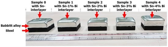
Figure 1.
Macro images of Babbitt–steel bimetal composites with different Sn–Bi interlayer compositions.
As shown in Figure 2, the microstructures of (a) re-melted Babbitt (Babbitt zone of bimetal composite) after pouring on steel substrate and (b) as-received steel solid substrate were observed. It was observed that the precipitates SbSn and Cu6Sn5 in a matrix of Sn–Sb–Cu were clearly defined. It was reported [30,31,32] that the chemical composition constituent variation of Babbitt alloy significantly changes the resulting solidification microstructure precipitates. Babbitt contains less than 8 percent Sb, fine precipitates of SbSn and needles/circular shapes of Cu6Sn5 in a Sn–Sb–Cu matrix are observed. The solid carbon steel microstructure is shown in Figure 2b, which reveals ferrite and pearlite phases. The relatively higher percentage of ferrite (white phase) and lower percentage pearlite (black phase) confirms the lower percentage C contents in the steel (0.12).
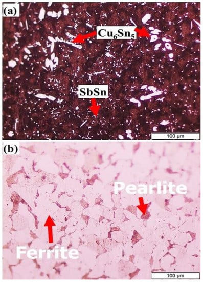
Figure 2.
Microstructures of (a) Babbitt alloy and (b) carbon steel substrate, used for preparing bimetallic composite.
The main precipitate phase in Babbitt containing ≤ 8 wt.% Sb is Cu6Sn5 (star and needle-like shape) in the background of soft matrix rich in the tin are observed. Which was confirmed by SEM micrograph and EDS analysis of selected area (see Figure 3a,b). EDS was used to confirm the presence of the Cu6Sn5 main precipitate phase in Babbitt containing ≤ 8 wt.% Sb using only internal standards of the manufacturer. The soft matrix of Babbitt acts as solid lubricant in bearings and the embedded intermetallic phases lead to enabling the required carrying load.
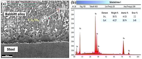
Figure 3.
(a) SEM Micrograph of Babbitt–steel composite microstructure, (b) EDS spectrum of selected area in (a).
Cross-section interfacial structure of Babbitt–steel composite with Sn interlayer at the center, near the edge, and at the interfacial bimetal edge are given in Figure 4. There is typically a small unbonded area at the edge of bimetal composites in the majority of liquid–solid compound castings, as shown in Figure 4a. During the tinning process, there was probably insufficient interlayer metal at the substrate edge and a higher cooling rate at the mold edge that resulted in these unbonded areas.
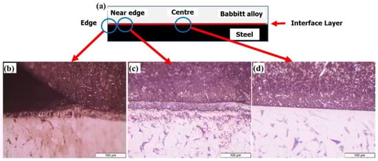
Figure 4.
Cross section interfacial structure of Babbitt–steel composite with Sn interlayer, (a) Schematic drawing for Babbitt–steel composite with interlayer, (b) microstructure of interfacial bimetal at the edge, (c) microstructure of interfacial bimetal near edge, (d) microstructure of interfacial bimetal at the center.
The microstructure of interfacial bimetal near the edge shows a clear unsolved Sn interlayer (Figure 4b) that resulted from the relatively higher cooling rate near the edge, the temperature of metallic mold and liquid Babbitt pouring temperature. Otherwise, a complete dissolving Sn interlayer at interfacial bimetal center is observed (Figure 4c). The relatively lower cooling rate at the bimetal interface center enables the Sn-interlayer to melt and be alloyed with poured liquid Babbitt. The observed fine precipitates in Babbitt matrix in interfacial layer prove the dilution of Babbitt with Sn interlayer.
Figure 5 shows the Babbitt–steel composite’s near-edge interfacial microstructure, which includes Sn and Sn–(1–4%) Bi interlayers. Clear interlayers are observed in all Babbitt–steel composites at the interfacial near the edge. Figure 6 shows the layer thickness of a Babbitt–steel composite containing Sn and Sn–(1–4%) Bi interlayers near-edge interfacial. As shown in Figure 5 and Figure 6, adding Bi to the Sn interlayer can change the interlayer’s thickness. The Babbitt–steel composite’s interlayer thickness decreases as the proportion of Bi to Sn interlayer increases. Up until the lowest melting points of eutectic temperature (139 °C), the melting points of Sn–Bi alloys decrease. For a Bi content of 0 to 57 wt%, the Sn–Bi alloys have melting points ranging from 139 to 232 degrees Celsius [33].
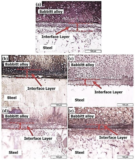
Figure 5.
Near-edge interfacial microstructure of Babbitt–steel composite with Sn and Sn–Bi interlayers, (a) bimetal with Sn interlayer, (b) bimetal with Sn + 1% Bi interlayer, (c) bimetal with Sn + 2% Bi interlayer, (d) bimetal with Sn + 3% Bi interlayer, (e) bimetal with Sn + 4% Bi interlayer.
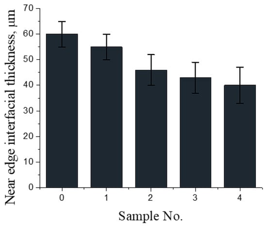
Figure 6.
Edge interfacial thickness of Babbitt–steel composite with Sn and Sn–Bi interlayers, (0) bimetal with Sn interlayer, (1) bimetal with Sn + 1% Bi interlayer, (2) bimetal with Sn + 2% Bi interlayer, (3) bimetal with Sn + 3% Bi interlayer, (4) bimetal with Sn + 4% Bi interlayer.
According to the Sn–Bi primary phase diagram, the maximum solubility of Bi in Sn is approximately 21 wt%. Sn–Bi alloys up to eutectic Sn–Bi solder have a higher Bi content, making it possible to realize that soldering at lower temperatures offers a potential replacement for Sn-37Pb solder [34]. The Sn–Bi solder of varying Bi content’s microstructure and mechanical properties have been investigated [35,36,37,38,39,40]. Using the nano-indentation method, the creep performance of Sn–Bi with varying amounts of Bi was examined [35], and the transition stress decreased with increasing Bi content. Sn–4.5Bi solder was found to have the highest hardness and bend fracture energy of Sn-Bi with differing Bi content [35,36]. Moreover, the directionally solidified Sn–Bi alloys are investigated for hypoeutectic solders near to eutectic. Bi addition would increase the mechanical properties of Sn–Bi solder [28,29,30,31,32,33,34,35,36,37,38,39].
Figure 7 shows the center interfacial microstructure of Babbitt–steel composites containing Sn and Sn–Bi interlayers with different Bi content. During the process of pouring liquid Babbitt on the tinned steel surface-inserted mold, it is plain to see that Sn interlayer bimetal is diluted with Babbitt alloy. Fine precipitates make up a novel interlayer composition. Otherwise, the complete dissolution of the Sn–Bi interlayer with the poured liquid Babbitt causes the addition of Bi to the Sn interlayer to significantly alter the structure of the interface layer.
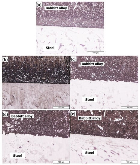
Figure 7.
Centre interfacial microstructure of Babbitt-steel composites with Sn and Sn–Bi interlayers, (a) bimetal with Sn interlayer, (b) bimetal with Sn + 1% Bi interlayer, (c) bimetal with Sn + 2% Bi interlayer, (d) bimetal with Sn + 3% Bi interlayer, and (e) bimetal with Sn + 4% Bi interlayer.
Sn–Bi soldering alloys’ higher wettability and lower melting temperature frequently necessitate a higher percentage of Bi. Otherwise, the risk of brittle fracture in Sn–Bi alloys rises with increasing Bi content [26]. Figure 8 shows SEM cross section microstructure of Babbitt–steel composites contain Sn–2%Bi and Sn–4% Bi interlayers alloy near edge and at center. A distinct layer of undissolved Sn–Bi near the edge is observed for both Sn–Bi alloys. Otherwise, the center is completely covered in dissolved interlayers. EDS spectrum, analysis, and line scan of Babbitt–steel interfacial areas near edges and centers are depicted in Figure 9, Table 2, and Figure 10. The interface region near the edge has a higher Bi content. Interfacial microcracks and voids clearly increase as the Bi content in the initial Sn–Bi interlayer alloy (after tinning) rises.
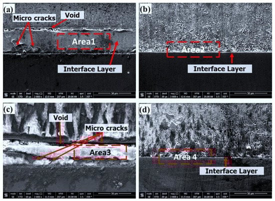
Figure 8.
SEM cross section micrographs of Babbitt-steel composites, (a) Sn–2%Bi interlayer alloy near edge, (b) Sn–2%Bi interlayer alloy at center, (c) Sn–4%Bi interlayer alloy near edge, (d) Sn–4%Bi interlayer alloy at center.
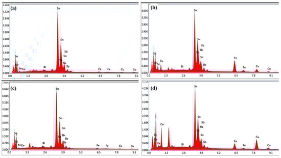
Table 2.
Results of EDS analysis for points indicated in Figure 9a–d.
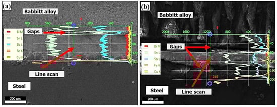
Figure 10.
EDS line scan of Babbitt–steel interfacial areas, (a) Sn–2% Bi interlayer alloy near edge, (b) Sn–4%Bi interlayer alloy near edge.
As the eutectic Sn-Bi solder is too brittle, the properties of the eutectic Sn–Bi soldering alloy are limited even though it has a desired low melting point of 138 °C [40]. As a result, numerous studies have been conducted on the welding properties of Sn–Bi alloys with a lower Bi content [34,35,36]. Rather than a hard/brittle matrix interlayer, a soft matrix with some hard precipitates is needed to improve the interface structure and shear strength of Babbitt/steel bimetal composites [21,23]. The soft matrix with some hard precipitates can improve the shear strength between the Babbitt and its substrate as well as improving bimetal loading capacity. For this reason, hypo-eutectic Sn–Bi interface layers with a lower percentage of Bi have been used in the current study.
Babbitt–steel interfacial areas near edges of Sn–2% Bi interlayer and Sn–4% Bi interlayer alloys are depicted in an EDS line scan in Figure 10. Sn–Bi alloys’ Bi content, which ranges from 2% to 4%, clearly increases the interface gaps between Babbitt and steel. According to the binary phase diagram [41], it is believed that increasing the Bi content of a hypo-eutectic Sn–Bi alloy lowers its melting point. The interlayer thickness between Babbitt and steel will decrease as a result of the lower melting point of the Sn-Bi alloy’s interlayer area near the edge, as shown in Figure 6. A re-melting of the higher portion of the Sn–Bi interlayer combined with Babbitt molten metal is anticipated for a higher Bi content in Sn–Bi interlayer alloy. With increasing amounts of the re-melted Sn–Bi alloy, the micro-shrinkage and voids increase due to the re-melting, mixing, and solidification processes.
A quantitative measurement for the effect of Bi additions to Sn interlayer on the interfacial hardness of the Babbitt–steel bimetal composite is shown in Figure 11. In general, the addition of Bi to the Sn-interlayer of the Babbitt–steel composite improves the interfacial hardness. In addition, it can be observed that increasing the Bi content increases the interfacial bimetal hardness. The higher the Bi content, the harder the interfacial bimetal is. The increase in hardness brought about by the rise for Bi could be attributed to an increase in the brittle Bi precipitate present in the Sn matrix, which has limited solubility in Sn.
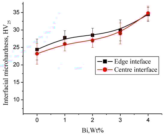
Figure 11.
Influence of Bi additions on Sn interfacial hardness of Babbitt–steel bimetal composite.
The average shear strength of Babbitt–steel bimetal composites values of Sn and Sn–Bi interlayers containing four different Bi content of bimetallic composite interfaces are shown in Figure 12. The addition of Bi to Sn interlayer increased the shear strength of Babbitt–steel bimetal composites up to 28.27 MPa with 1 wt.% alloying showing a rise of 10.3% in comparison to reference pure Sn interlayer. However, a further rise in Bi addition up to 4.0 wt% decrease in shear strength was observed. Using Sn–1% Bi interlayer alloy shows a relatively better interfacial microstructure beside of a free of micro-cracks or voids. Moreover, the decreased content of brittle Bi (1%) increases the interlayer shear strength.
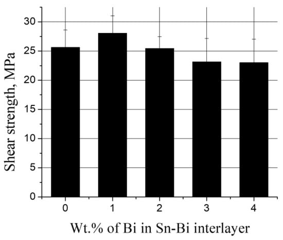
Figure 12.
Influence of Bi additions to Sn interlayer on shear strength of Babbitt–steel bimetal composites.
According to the findings, the Babbitt–steel bimetallic composite’s shear strength increases when the Sn–Bi interlayer alloy contains 1 wt% Bi, which decreases when the Bi content is increased further. The effect of increasing the amount of Bi in the Sn–Bi alloy on its brittle fracture could be one reason. In addition, we note the negative volume change of Sn–Bi during liquid Babbitt molten metal pouring onto the Sn–Bi tinned steel upon re-melting [41]. According to previous discussions, Sn–Bi interlayer alloys with higher percentages of Bi have a higher hardness but are more brittle than Sn–Bi interlayers on steel substrates with lower percentages of Bi. The addition of Bi to the Sn interlayer for Babbitt–steel bimetallic composites should be kept to a low percentage (≤1), according to all discussions, to improve to some extent the shear strength and ductility of the Sn–Bi interlayer alloy.
4. Conclusions
For Babbitt–steel bimetallic composites, a new class of tinning interlayer materials with Bi percentages of 1 wt%, 2 wt%, 3 wt%, and 4 wt%. was developed. The interfacial microstructure and Babbitt–steel wettability of the Sn interlayer were found to improve when Bi was added. Sn/Sn–Bi interlayers that remain unsolved are evident in the microstructure of interfacial bimetal near the edge due to the relatively higher cooling rate near the edge. The addition of Bi to the Sn interlayer changes significantly the interface layer structure at the center of the interface due to a complete dissolving of the Sn–Bi interlayer with the poured liquid Babbitt. The increase of the hardness by increasing Bi content could be explained by increasing the brittle Bi precipitate in Sn matrix due to the limited solubility of Bi in Sn at room temperature. The addition of Bi to the Sn interlayer increased the shear strength of Babbitt–steel bimetal composites up to 28.27 MPa with 1 wt.% alloying showing a rise of 10.3% in comparison to reference pure Sn interlayer. In conclusion, the Sn–Bi interlayer alloy’s shear strength and ductility can both be enhanced by maintaining a low Bi addition percentage (≤1 wt%). For future endeavors to optimize the fabrication of Babbitt–steel bimetallic composite with high-quality and long-life bimetal bonding, the ideal pouring temperature and preheating mold should be taken into consideration.
Funding
This research received no external funding.
Institutional Review Board Statement
Not applicable.
Informed Consent Statement
Not applicable.
Data Availability Statement
Not applicable.
Conflicts of Interest
The authors declare no conflict of interest.
References
- Ramadan, M.; Fathy, N.; Abdel Halim, K.S.; Alghamdi, A.S. New trends and advances in bi-metal casting technologies. Int. J. Adv. Appl. Sci. 2019, 6, 75–80. [Google Scholar] [CrossRef]
- Gebretsadik, D.W.; Hardell, J.; Prakash, B. Tribological performance of tin-based overlay plated engine bearing materials. Tribol. Int. 2015, 92, 281–289. [Google Scholar] [CrossRef]
- Ünlü, B. Determination of the tribological and mechanical properties of SnPbCuSb (white metal) bearings. Mater. Sci. 2011, 46, 478–485. [Google Scholar] [CrossRef]
- García Gutiérrez, I.; Elduque, D.; Pina, C.; Tobajas, R.; Javierre, C. Influence of the Composition on the Environmental Impact of a Casting Magnesium Alloy. Sustainability 2020, 12, 10494. [Google Scholar] [CrossRef]
- Jena, T.; Kaewunruen, S. Life Cycle Sustainability Assessments of an Innovative FRP Composite Footbridge. Sustainability 2021, 13, 13000. [Google Scholar] [CrossRef]
- Luo, G.; Chai, C.; Liu, J.; Xiao, Y.; Chen, Y.; Xu, F. Investigations on the Mechanical Properties of Composite T-Joints with Defects under Bending Loading. Sustainability 2022, 14, 16609. [Google Scholar] [CrossRef]
- Joustra, J.; Bakker, C.; Bessai, R.; Balkenende, R. Circular Composites by Design: Testing a Design Method in Industry. Sustainability 2022, 14, 7993. [Google Scholar] [CrossRef]
- Ramadan, M.; Khaliq, A.; Hafez, K.M.; Alghamdi, A.S.; Fathy, N.; Harraz, F.A.; Ayadi, B.; Abdel Halim, K.S. Super Bonding Strength of Al2O3 Nanoparticles Reinforced Sn Interlayer Steel/Aluminum Bimetal Casting. Crystals 2022, 12, 324. [Google Scholar] [CrossRef]
- Ramadan, M.; Hafez, K.M.; Alghamdi, A.S.; Ayadi, B.; Abdel Halim, K.S. Novel Approach for Using Ductile Iron as Substrate in Bimetallic Materials for Higher Interfacial Bonding Bearings. Int. J. Met. 2022, 16, 987–1000. [Google Scholar] [CrossRef]
- Ku, A.; Ogunseitan, O.; Saphores, J.-D. Lead-Free Solders: Issues of Toxicity, Availability and Impacts of Extraction. In Proceedings of the Conference Paper in 53rd Electronic Components and Technology Conference, 2003, New Orleans, LA, USA, 27–30 May 2003. [Google Scholar] [CrossRef]
- Tillmann, W.; Hagen, L.; Kensy, M.D.; Abdulgader, M.; Paulus, M. Microstructural and Tribological Characteristics of Sn-Sb-Cu-Based Composite Coatings Deposited by Cold Spraying. J. Therm. Spray Technol. 2020, 29, 1027–1039. [Google Scholar] [CrossRef]
- Cavallaro, G.; Lazzara, G.; Lisuzzo, L.; Milioto, S.; Parisi, F. Filling of Mater-Bi with Nanoclays to Enhance the Biofilm Rigidity. J. Funct. Biomater. 2018, 9, 60. [Google Scholar] [CrossRef] [PubMed]
- Asrafali, S.P.; Periyasamy, T.; Raorane, C.J.; Raj, V.; Kim, S.C. The Thermo-Mechanical and Dielectric Properties of Superhydrophobic Pbz/TiO2 Composites. Sustainability 2022, 14, 13401. [Google Scholar] [CrossRef]
- Ramadan, M. Interface Characterization of Bimetallic Casting with a 304 Stainless Steel Surface Layer and a Gray Cast Iron Base. In Advanced Materials Research; Trans Tech Publications Ltd.: Baech, Switzerland, 2015; pp. 993–998. [Google Scholar] [CrossRef]
- Fathy, N.; Ramadan, M. Influence of volume ratio of liquid to solid and low pouring temperature on interface structure of cast Babbitt-steel bimetal composite. AIP Conf. Proc. 2018, 1966, 020028. [Google Scholar] [CrossRef]
- Wrobel, T. Characterization of Bimetallic Castings with an Austenitic Working Surface Layer and an Unalloyed Cast Steel Base. J. Mater. Eng. Perform. 2014, 23, 1711–1717. [Google Scholar] [CrossRef]
- Zhao, J.; Shangguan, J.; Gu, C.; Jin, B.; Shi, Y. Microstructures and mechanical properties of TC4/AZ91D bimetal prepared by solid–liquid compound casting combined with Zn/Al composite interlayer. Trans. Nonferrous Met. Soc. China 2022, 32, 1144–1158. [Google Scholar] [CrossRef]
- Shin, J.; Kim, T.; Lim, K.; Cho, H.; Yang, D.; Jeong, C.; Yi, S. Effects of steel type and sandblasting pretreatment on the solid-liquid compound casting characteristics of zinc-coated steel/aluminum bimetals. J. Alloys Compd. 2019, 778, 170–185. [Google Scholar] [CrossRef]
- Jiang, W.; Fan, Z.; Li, C. Improved steel/aluminum bonding in bimetallic castings by a compound casting process. J. Mater. Process. Technol. 2015, 226, 25–31. [Google Scholar] [CrossRef]
- Ramadan, M.; Hafez, K. Interfacial microstructure and hardness of Sn-Based Babbitt/C93700 Cu-Pb-Sn bimetallic materials. Mater. Today Proc. 2021, 45, 5074–5080. [Google Scholar] [CrossRef]
- Ramadan, M.; Alghamdi, A.S.; Subhani, T.; Halim, K.S.A. Fabrication and Characterization of Sn-Based Babbitt Alloy Nanocomposite Reinforced with Al2O3 Nanoparticles/Carbon Steel Bimetallic Material. Materials 2020, 13, 2759. [Google Scholar] [CrossRef]
- Ramadan, M.; Ayadi, B.; Rajhi, W.; Alghamdi, A.S. Influence of Tinning Material on Interfacial Microstructures and Mechanical Properties of Al12Sn4Si1Cu /Carbon Steel Bimetallic Castings for Bearing Applications. KEM 2020, 835, 108–114. [Google Scholar] [CrossRef]
- Fathy, N. Interfacial Microstructure and Bonding Area of Sn-based Alloy-GG25 Gray Iron Bimetallic Material Using Flux, Sn, and Sn-Zn Interlayer Compound Casting. Eng. Technol. Appl. Sci. Res. 2022, 12, 8416–8420. [Google Scholar] [CrossRef]
- Suganuma, K.; Kim, S.J.; Kim, K.S. High-temperature lead-free solders: Properties and possibilities. JOM J. Miner. Met. Mater. Soc. 2009, 61, 64–71. [Google Scholar] [CrossRef]
- Hu, X.; Li, Y.; Liu, Y.; Min, Z. Developments of high strength Bi-containing Sn0.7Cu lead-free solder alloys prepared by directional solidification. J. Alloys Compd. 2015, 625, 241–250. [Google Scholar] [CrossRef]
- Wang, F.; Huang, Y.; Zhang, Z.; Yan, C. Interfacial Reaction and Mechanical Properties of Sn-Bi Solder joints. Materials 2017, 10, 920. [Google Scholar] [CrossRef] [PubMed]
- Delhaise, A.M.; Bagheri, Z.; Meschter, S.; Snugovsky, P.; Kennedy, J. Tin Whisker Growth on Electronic Assemblies Soldered with Bi-Containing, Pb-Free Alloys. J. Electron. Mater. 2012, 50, 842–854. [Google Scholar] [CrossRef]
- Ramadan, M.; Alghamdi, A.S.; Hafez, K.M.; Subhani, T.; Abdel Halim, K.S. Development and Optimization of Tin/Flux Mixture for Direct Tinning and Interfacial Bonding in Aluminum/Steel Bimetallic Compound Casting. Materials 2020, 13, 5642. [Google Scholar] [CrossRef] [PubMed]
- Ayadi, B.; Ramadan, M. Novel and simple technique for interfacial shear strength of liquid-solid compound casting specimen. Mater. Today Proc. 2021, 47, 2299–2304. [Google Scholar] [CrossRef]
- Dean, R.; Evans, C. Plain bearing materials: The role of tin. Tribol. Int. 1976, 9, 101–108. [Google Scholar] [CrossRef]
- Pratt, G.C. Materials for plain bearings. Int. Metall. Rev. 1973, 18, 62–88. [Google Scholar] [CrossRef]
- Moazami Goudarzi, M.; Jenabali Jahromi, S.; Nazarboland, A. Investigation of characteristics of tin-based white metals as a bearing material. Mater. Des. 2009, 30, 2283–2288. [Google Scholar] [CrossRef]
- Yeh, C.H.; Chang, L.S.; Straumal, B.B. Wetting transition of grain boundaries in the Sn-rich part of the Sn–Bi phase diagram. J. Mater. Sci. 2011, 46, 1557–1562. [Google Scholar] [CrossRef]
- Shen, L.; Septiwerdani, P.; Chen, Z. Elastic modulus, hardness and creep performance of SnBi alloys using nanoindentation. Mater. Sci. Eng. A 2012, 558, 253–258. [Google Scholar] [CrossRef]
- Lai, Z.; Ye, D. Microstructure and fracture behavior of non eutectic Sn–Bi solder alloys. J. Mater. Sci. Mater. Electron. 2016, 27, 3182–3192. [Google Scholar] [CrossRef]
- Ye, D.; Du, C.; Wu, M. Microstructure and mechanical properties of Sn–xBi solder alloy. J. Mater. Sci. Mater. Electron. 2015, 26, 3629–3637. [Google Scholar] [CrossRef]
- Osório, W.R.; Peixoto, L.C.; Garcia, L.R.; Mangelinck-Noël, N.; Garcia, A. Microstructure and mechanical properties of Sn–Bi, Sn–Ag and Sn–Zn lead-free solder alloys. J. Alloys Compd. 2013, 572, 97–106. [Google Scholar] [CrossRef]
- Silva, B.L.; Reinhart, G.; Nguyen-Thi, H.; Mangelinck-Noël, N.; Garcia, A.; Spinelli, J.E. Microstructural development and mechanical properties of a near-eutectic directionally solidified Sn–Bi solder alloy. Mater. Charact. 2015, 107, 43–53. [Google Scholar] [CrossRef]
- Silva, B.L.; da Silva, V.C.E.; Garcia, A.; Spinelli, J.E. Effects of Solidification Thermal Parameters on Microstructure and Mechanical Properties of Sn-Bi Solder Alloys. J. Electron. Mater. 2017, 46, 1754–1769. [Google Scholar] [CrossRef]
- Zhao, J.; Sun, K.; Liang, G.; Xu, C.; Zhao, J.; Xue, F.; Zhou, J. Effect of Zn additions on the microstructure and mechanical properties of Sn-Babbitt alloys fabricated by arc deposition. J. Mater. Res. Technol. 2021, 15, 6726–6735. [Google Scholar] [CrossRef]
- Liu, Y.; Tu, K. Low melting point solders based on Sn, Bi, and In elements. Mater. Today Adv. 2020, 8, 100115. [Google Scholar] [CrossRef]


Disclaimer/Publisher’s Note: The statements, opinions and data contained in all publications are solely those of the individual author(s) and contributor(s) and not of MDPI and/or the editor(s). MDPI and/or the editor(s) disclaim responsibility for any injury to people or property resulting from any ideas, methods, instructions or products referred to in the content. |
© 2023 by the author. Licensee MDPI, Basel, Switzerland. This article is an open access article distributed under the terms and conditions of the Creative Commons Attribution (CC BY) license (https://creativecommons.org/licenses/by/4.0/).