Article

Seismic Resilience Assessment of Curved Reinforced Concrete Bridge Piers through Seismic Fragility Curves Considering Short- and Long-Period Earthquakes

1
Civil and Environmental Engineering Program, Graduate School of Advanced Science and Engineering, Hiroshima University, Hiroshima 739-8527, Japan
2
Faculty of Civil and Environmental Engineering, Tarbiat Modares University, Tehran P.O. Box 14115-397, Iran
3
Department of Civil Engineering, Marand Technical Faculty, University of Tabriz, Tabriz P.O. Box 54138-89741, Iran
*
Author to whom correspondence should be addressed.
Sustainability 2023, 15(10), 7764; https://doi.org/10.3390/su15107764
Submission received: 27 March 2023 / Revised: 29 April 2023 / Accepted: 2 May 2023 / Published: 9 May 2023

Abstract

:
Curved bridges are commonly used for logistics and emergencies in urban areas such as highway interchange bridges. These types of bridges have complicated dynamic behaviors and also are vulnerable to earthquakes, so their functionality is a critical parameter for decision makers. For this purpose, this study aims to evaluate the bridge seismic resilience under the effects of changes in deck radius (50, 100, 150 m, and infinity), pier height irregularity (Regular and Irregular), and incident seismic wave angle (0°, 45°, and 90°) under short- and long-period records. In the first step, fragility curves are calculated based on the incremental dynamic analysis and probabilistic seismic demand models. Finally, seismic resilience curves/surfaces are constructed and their interpolated values of the log-normal distribution function presented for assessing system resilience. It is found that when long-period records are applied in one given direction, the angle of incidence has the most significant effect on seismic resilience, and bridges are most vulnerable when the angle of incidence tends to 0°. The effect of deck radius on seismic resilience became more remarkable as the angle of incidence increased. Additionally, results indicate that the bridge vulnerability in long-period records is more significant than that under short-period records.

1. Introduction

Bridges play essential roles in economic activities such as logistics, emergency medical services, emergency routes for firefighting, and rescue operations such as transportation hubs on highways and in urban areas. Therefore, system identification of bridges using numerical methods has drawn researchers’ attention in recent years [1,2,3]. The seismic performance of bridges depends on factors such as the geometric properties and materials of the bridge as well as the characteristics of earthquakes [4]. Japan is located in one of the most active tectonic zones of the world, and earthquakes have caused enormous damage to many civil engineering infrastructures, such as bridges, in Japan [5]. In this regard, bridges are known to be highly vulnerable to earthquakes, as represented by the collapse of bridges caused by the Northridge Earthquake in 1994 and the Hyogo-Nanbu Earthquake in 1995, which is attributed to short-period ground motions. However, considering the rapid increase in large structures such as fluid storage tanks [6] and reinforced concrete bridges [7], long-period ground motions should be given more attention and consideration [8]. In addition, it is necessary to avoid permanent damage to bridge components to maintain functionality after an earthquake [9]. Table 1 shows all definitions of abbreviations and acronyms used in the present study.
Long-period ground motions are generally divided into two types: long-period ground motions observed near faults (from now on, near long-period ground motions) and long-period ground motions observed far away from the epicenter (from now on, distant long-period ground motions). In this line, Mahmood et al. [10] investigated one-dimensional equivalent linear ground response analysis for Margalla Tower during the Muzaffarabad Earthquake and compared new calculated spectral acceleration with the response spectra of Islamabad. In addition, Mahmood et al. [11] evaluated the effect of local site conditions on the seismic hazard of the relocated town of Balakot as a result of the complete destruction of the old Balakot due to the Muzaffarabad Earthquake. Koketsu and Miyake [12] stated that distant long-period ground motion might have a more significant impact than near long-period ground motion. Therefore, one of the purposes of this study is to investigate the effect of distant long-period ground motions on the seismic vulnerability of bridges. The distant long-period ground motion will be referred to as the long-period ground motion. Choi et al. [13] analyzed common bridges in central and southeastern United States seismic areas. It was observed that the multi-span simple support and continuous steel girder bridge are very vulnerable structures during earthquake events. Yi et al. [14] studied the effectiveness of viscous dampers on seismic control of single-tower cable-stayed bridges subjected to near-field ground motions. Ma et al. [15] investigated the effects of near-fault pulse-like ground motions and the uncertainties in bridge modeling on the seismic demands of regular, continuous highway bridges.
Research on the seismic resistance of reinforced concrete bridges has been actively conducted during the last few years [16,17]. In this regard, Okazawa et al. [18] conducted the seismic response analysis of a reinforced concrete pier using seismic waves recorded at the Takatori station during the Southern Hyogo Prefecture Earthquake in 1995 in Japan. They calculated the seismic response analyses using the K computer at the RIKEN Advanced Institute for Computational Science. They compared the results with a seismic experiment in E-Defense to confirm the computational approach. Dezfuli and Alam [19] evaluated three types of bearings used in the bridges: Low-Damping Natural Rubber Bearings (LDNRBs), High-Damping Laminated Rubber Bearings (HDLRBs), and Laminated Rubber Bearings (LRBs), to investigate the effect of bearings, as one of the most vulnerable components, on seismic resistance. As a result, bridges with low-damping natural rubber bearings, which have the lowest energy dissipation capacity, are fragile, while bridges with high-damping laminated rubber bearings are least likely to be damaged. Mao et al. [20] presented an assessment of concrete bridge piers with different reinforcement alternatives and conducted numerical studies to investigate the relative performance of different bridge piers under seismic loadings. In addition, Román et al. [21] determined the relevant factors required to increase the seismic resilience of roadway bridges and bridge networks according to the crisp Decision-Making and Trial Evaluation Laboratory (DEMATEL) and rough DEMATEL methods.
In recent years, research on the central angle of curved bridges has attracted more attention as one of the parameters that significantly affect bridges’ seismic resilience. Tondini and Stojadinovic [22] analyzed and evaluated four central angles with a magnitude–distance bin method using four sets of ground motions separated by magnitude and distance. As a result, it was reported that the demand for lateral displacement ductility of piers increased with the decrease in the deck radius. In contrast, the demand for longitudinal displacement ductility did not change. Amirihormozaki et al. [23] performed seismic analysis by assuming the central angle of the bridge as 0, 30, 60, and 90 degrees. They found that the complex combination of twisting and bending of members under static or dynamic loads may produce a 33% increase in seismic demand for pier ductility. In this line, Gupta and Sandhu [24] evaluated the seismic response of a three-span continuous Reinforced Concrete (RC) skew-curved concrete box-girder bridge under different vibration situations. The results showed that in-plane moments in the longitudinal and transverse directions are considerably affected by including bridge skewness and curvature.
In addition to the central angle, the height of the piers also shows remarkable effects on earthquake resistance [25,26,27]. Abbasi et al. [28] evaluated the impact of irregularities with different pier heights on bridges with intra-span hinges among the many multi-span RC box-girder bridges built in California. It suggests that the bridge will become more vulnerable as the irregularity increases. On the other hand, for piers, ductile demand will increase for short piers. Tamaddon et al. [29] proposed a theoretical method using structural dynamic relationships to assess the effect of central angle on the seismic response of curved bridges with rubber bearings exposed to strong vertical ground motions.
It should be noted that most of the research has focused on the intensity level, magnitude, and distance from the epicenter of the ground motion input to the bridge model. In this line, Yamamoto et al. [30] analyzed two existing seismic isolated bridges by applying short- and long-period ground motions. The results showed that the maximum responses of the structure (bending moment, shear force, and displacement) are significantly more when long-period ground motion was applied to the piers than short-period ground motion. Tomi et al. [31] conducted a dynamic analysis of multi-span continuous viaducts using surface seismic waves to investigate the relationship between long-period ground motions and the seismic behavior of structures. They reported that a considerable response value occurs when the predominant frequency region is close to the natural period of the bridge. Additionally, Todorov and Billah [32] studied the vulnerability of an RC bridge pier under long-duration, near-fault, and far-field ground motions through fragility curves. The results showed that since the current design guidelines do not consider the characteristics of the earthquake records, performance-based design criteria should be reviewed to assess the parameters mentioned. In addition, Peng et al. [33] proposed an invented device to improve the post-earthquake resilience of bridge infrastructure called a two-stage friction pendulum bearing based on a traditional friction pendulum bearing.
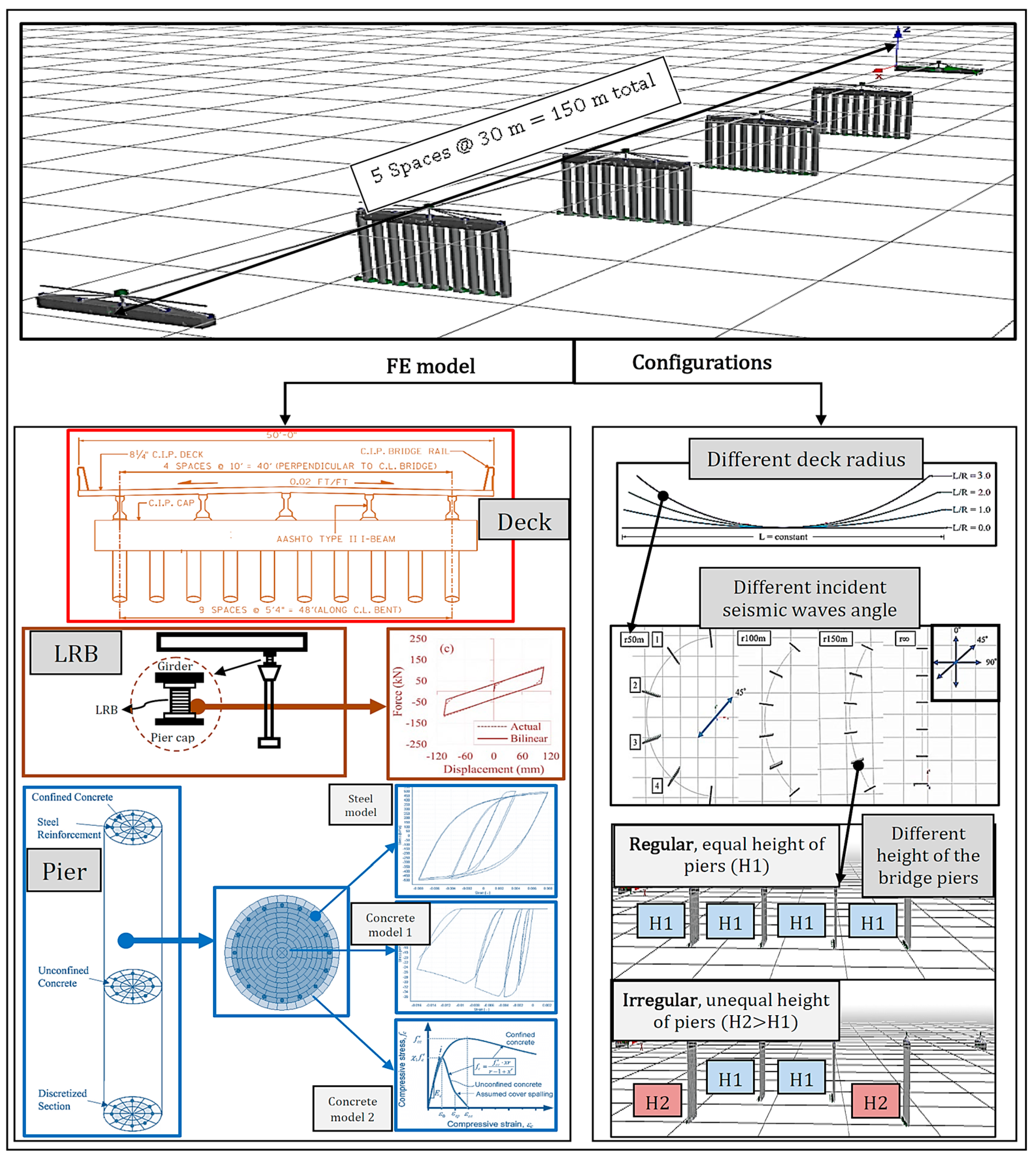
To date, research on seismic resistance evaluation of bridge piers considering long-period ground motions has been conducted. However, examining the effects of pier height irregularity, curvature, and load direction on the seismic resistance of reinforced concrete bridges when long-period ground motion is input is still insufficient. It should be noted that although piers with different cross-sectional shapes are sensitive to the incident seismic wave angle, the focus of this research is on the investigation of the most common circular constant cross-section with pier height irregularity, in which the piers near the abutment are set higher than the inner piers. In this regard, this research aims to simultaneously evaluate the seismic resilience of reinforced concrete bridge piers in an integrated approach by considering the effects of two main factors; the first one is the structural configurations, including changes in deck radius (50, 100, 150 m, and infinity) and pier height irregularity (Regular and Irregular cases). In addition, the second factor is the site conditions, including incident seismic wave angle (0°, 45°, and 90°) and short- and long-period seismic ground motions. For this purpose, a set of Incremental Dynamic Analyses (IDAs) is performed for each case. In the next step, the probability of structural damage as fragility curves at four damage states (i.e., slight, moderate, extensive, and complete) is calculated based on the Probabilistic Seismic Demand Models (PSDMs) and the mean response of the set of records for a wide range of seismic intensity levels of 0 to 1.5 g. Then, seismic resilience curves are constructed for each considered scenario using short- and long-period earthquakes as ground motion input. Additionally, seismic resilience surfaces are calculated for each case based on the proposed framework. In addition, a parametric study is conducted for the short-period ground motion to evaluate the effect of the ground motion period. The impacts of changes in curvature and pier height irregularity on the seismic resilience are also assessed compared to the case where long-period ground motion is used as input. Finally, the median and log-standard deviation values of the interpolated log-normal distribution functions for system resilience right after a seismic hazard event with different intensity levels are presented. Figure 1 plots a broad context of the seismic resilience assessment process of the present paper.

2. Seismic Resilience and Fragility Assessment

2.1. Seismic Fragility Curves and Damage Indices

In order to evaluate the seismic resilience of infrastructure, it is crucial to evaluate the performance of the bridge when it is excited by a specific ground motion. For this purpose, fragility curves should be examined in the first step through IDAs and PSDMs. Next, the resilience index can be calculated based on fragility and restoration functions [34]. There are various fragility curves with different types of Intensity Measurements (IMs) with different DIs, such as Peak Ground Acceleration (PGA), Peak Ground Velocity (PGV), Arias Intensity (AI), Spectral Acceleration (Sa), and Spectral Displacement (Sd) at the first natural period as proposed in the literature. However, the PGA is acknowledged as the most effective and optimum IM. In this regard, Padgett and DesRoches [35] identified the PGA as the optimum IM to describe the severity of the earthquake ground motion. Additionally, several studies have used the PGA due to its overall efficiency, sufficiency, and practicality in seismic hazard computation and reasonably good ability to predict demand [36,37]. In addition, owing to the physical meaning of the drift, this parameter can be selected as the Damage Index (DI), in which the damage rate in structures could be demonstrated accurately. It should be mentioned that the method for estimating the fragility curves does not change when changing the DI types and the damage threshold. Knowing this fact and considering the damage type of the bridge pier, a more relevant index is used in this paper.
In order to create fragility curves (i.e., slight, moderate, extensive, and complete), probabilistic seismic demand models are created first that connect the Engineering Demand Parameter (EDP) and the IM [38] for each bridge under study. This PSDM can be made using either the “scaling approach” or the “cloud approach.” The scaling approach creates the fragility curve by performing IDA [39], which scales the ground motion to various intensity levels and performs a non-linear time history response analysis. Therefore, the fragility curve is generally plotted using the relationship between the EDP and the IM. On the other hand, the cloud approach is used for analysis without changing (scaling) the intensity level of ground motion. A scaling approach is an effective tool for understanding the inelastic behavior of structures within the range of intensity measurements. The PSDM is generally obtained by regression analysis as given below [40]:
E D P = a I M b
where a and b are regression coefficients derived from the relationship between IM and EDP obtained by IDA. Further, Equation (1) can be rewritten as follows:
ln E D P = ln a + b ln I M
The standard deviation in this regression analysis is expressed by:
β = i = 1 n ln E D P i ln a b ln I M i 2 n 2
In which n indicates the total number of non-linear time history response analyses, and E D P i and I M i are the maximum EDP and IM in the i-th non-linear time history response analysis. The fragility curve is the probability of exceeding a specific damage state for intensity measurements of various intensity levels that can now be determined by [41]:
P E D D S k I M = ϕ 1 σ k ln E D P μ k
where ϕ · is the log-normal cumulative distribution function, D S k is the k-th damage state (i.e., slight, moderate, extensive, and complete), σ k is the normalized composite log-normal standard deviation corresponding to the k-th damage state, and μ k is the median value related to the k-th damage state. A detailed description of damage states is given in Table 2 in obedience to HAZUS [41]. In this regard, the median μ k and the normalized composite log-normal standard deviation σ k based on HAZUS [41] corresponding to each damage state in Equation (4) are used to create the fragility curve (see Table 2).

2.2. Seismic Resilience

Several studies have been conducted to evaluate the resilience concept and identify its major criteria [42,43]. In the present paper, resilience ( R t ) is the ability of infrastructure such as bridges to preserve a specified level of functionality during a control time ( T L C ) determined by the decision makers [44]. As shown in Figure 1, the highlighted area under the system performance function Q t is defined as the resilience index. The mentioned region is a non-stationary stochastic process, and each set illustrates a piecewise continuous function. The analytical relation for the resilience index is as follows [40]:
R t = t O E t O E + T L C Q t T L C d t
It is necessary to formulate two parameters of loss and recovery functions during and after interruption as a consequence of the occurrence of an extreme event (such as an earthquake) to calculate the system functionality Q t . From the mathematical viewpoint, this concept can be expressed as follows:
Q t = 100 % [ L I , T R E × H t t 0 E H t t 0 E + T R E × f r e c t , t 0 E , T R E ]
where L I , T R E demonstrates the loss function as a function of hazard intensity ( I ) and elapsed time to recover the infrastructure ( T R E ). In addition, f r e c and H · indicate the post-event recovery path and the Heaviside step functions of the infrastructure, respectively.
In Equation (5), for an ideally undamaged structure, Q t = 1 , leading to a resilience index R of 100%; however, its value falls immediately after an earthquake due to the structural damage. To calculate the resilience index ( R 0 ) right after an earthquake event (E) with a specified intensity, the loss of functionality in the given time must be calculated. In this line, the functionality ( Q 0 ) can be determined as a dimensionless cost quantity ( L 0 ), which is identified as cost of repair/cost of replacement. Thereby, the structure functionality or resilience index right after an earthquake event at t O E can be calculated as follows [40]:
R 0 = Q 0 = 1 L 0 = 1 k P E L S = k · r k
In which k represents the structural limit state (e.g., slight, moderate, extensive, complete) and P E ( L S = k ) implies the exceedance probability for the limit state k right after an earthquake event E. Lastly, r k at slight, moderate, extensive, and complete limit states of the bridge are considered to be 0.125, 0.35, 0.7, and 0.95, respectively [41].

3. Modeling of Bridge and Ground Motion Selection

3.1. Bridge Model

This paper considers a typical three-dimensional RC bridge with different configurations for assessing seismic resilience under different site situation effects. The bridge model in this study is created regarding the bridge approximately 22 km northeast of Memphis [19,45]. USGS data are used to define the design response spectra. These spectra represent the as-recorded geometric mean of two horizontal components and correspond to the AASHTO [46] Design Basis Earthquake (DBE) ground shaking having a 7% probability of exceedance in 75 years (a recurrence interval of approximately 1000 years) and the Maximum Considered Earthquake (MCE) ground shaking having a 3% probability of exceedance in 75 years (a recurrence interval of approximately 2500 years). The bridge under study is a 5-span reinforced concrete I-girder bridge with a total length of 150 m, and each length span is 30 m. In addition, each pier is supported by ten piles. Figure 2 demonstrates more details of the bridge modeled in the finite element SeismoStruct platform [47], and the details of the deck, LRB, and pier sections are plotted.
The material properties of concrete and reinforcing bars used in this study are presented in Table 3. The stress–strain relationships of concrete and reinforcing steel used for fiber elements follow the uniaxial non-linear constant confinement model suggested by Madas and Elnashai [48] that pursues the constitutive relationship presented by Mander et al. [49] together with the cyclic rules advised by Martinez-Rueda and Elnashai [50]. The concrete model can simulate the stress–strain relationship between constrained concrete (i.e., inside the lateral reinforcement) and unconstrained concrete (i.e., outside the lateral reinforcement) [51]. A uniaxial steel model originally programmed by Yassin [52] is used to model the reinforcement steel bar material. It is based on the simple stress–strain relationship proposed by Menegotto and Pinto [53] coupled with the isotropic hardening rules suggested by Filippou et al. [54]. The current implementation follows the procedure performed by Monti et al. [55]. To reach a higher numerical stability/accuracy under transient seismic loading, a supplementary memory rule introduced by Fragiadakis et al. [56] is also used.
Each pier is modeled using force-based 3D inelastic beam–column elements with fiber-defined cross-sections, as shown in Figure 2. In addition, non-linear inelastic beam–column (i.e., frame) elements are used to model piers and pier caps. The fiber element analysis is an analysis method that gives the constitutive rules of concrete and axial reinforcing bars based on bending theory. It expresses the non-linear restoring force characteristics of RC structures from the balance of forces in the cross-section. The fiber elements satisfy the assumption of flatness retention after cracking the concrete, ignoring shear deformation and assuming that concrete and rebar are entirely attached. The SeismoStruct program [46] usually recommends using 200 or more fiber elements for more complex sections exposed to high levels of inelasticity. Thus, this study also set the number of cross-section fibers to 200. It is also assumed that the pier is fixed at the lower end (i.e., the pier supports are assumed to be fixed). This simplified approach is used in several studies (e.g., see Ref. [19]). In this regard, Yamamoto et al. [30] examined the effects of long-period ground motion on road bridges. They did not model foundation structures such as footings, underground beams, or the ground. The reasons why they did not consider the effects of the interaction between the foundation structure and the ground are (1) even if a simplified model is used, the effect on the natural period is minor and (2) it leads to the shortening of analysis time. Therefore, in this study, the interaction between the foundation structure and the ground is ignored for the above reasons. Additionally, steel girders are modeled using elastic frame elements and remain elastic under seismic loadings. Girders are divided into several small discrete segments.
The mass of each segment is assumed to be equally distributed between the two adjacent nodes in the form of a point mass. The bridge’s deck is modeled using the elastic frame element in SeismoStruct [47]. Following the results of Tondini and Stojadinovic [22], the earthquake energy is dissipated mainly by the substructure or damping device. The deck is assumed to maintain elasticity and adopts elastic frame elements. According to Huff [45], the weight of the superstructure is 146 kN/m, and the deck model is placed at the center of gravity of the deck. Therefore, the mass distribution is simulated by dividing each span into six parts, and also the rigid link was used to connect the deck to the piers. Based on previous research [13], it can be stated that the response of the bridge is typically governed by the foundation, piers, and isolation bearings, assuming the stiffness of the superstructure has negligible effects on the seismic response of the bridge. The bearing model used for the bridge under study is the LRB model proposed by Dezfuli and Alam [19], represented by the bilinear kinematic model. The LRB has a planar area of 350 mm × 350 mm, and its total thickness is 70 mm. It should be noted that the bilinear model with kinematic hardening is the most suitable model available in SeismoStruct [46] when simulating the behavior of rubber bearings. In this respect, Raheem [56] also investigated seismic response of bridges with bidirectional coupled modeling of a base isolation bearing system. Figure 2 shows the bilinear behavior of the bearings used in this study. Regarding the properties of the bilinear model, the initial rigidity K 0 is 14.78 kN/mm, the yield force F y is 37.77 kN, and the post-yield hardening ratio (r) is 0.5. In addition, the stiffness, the energy dissipated per cycle, and the residual deformation are included in the considered LRB hysteretic model idealization based on Dezfuli and Alam [19]. To model LRB in SeismoStruct, the zero-length bearing elements with the mentioned properties (i.e., K 0 , F y , and r) are used in longitudinal and transverse directions.

3.2. Parameter Consideration

In this study, a parametric study is conducted, in which (1) curvature or deck radius, (2) earthquake direction (or incident seismic wave angle), and (3) the height of the piers are changed for evaluation. These analyses are performed to investigate how these parameters affect the seismic resistance of the target bridge. The bridge’s total length is kept unaltered, and only the deck radii are changed in various models for the parametric study. The total length of the bridge of this research is 150 m, and analyses are performed while changing the radius to 50 m, 100 m, 150 m, and ∞ (straight bridge), corresponding to L/R (total length/radius) = 3, 2, 1, and 0 (see Figure 2). In areas where earthquakes occur frequently, bridges must resist ground motion from all directions. However, it is difficult to predict the direction of the earthquake because it depends on the position of the epicenter. Additionally, it is reported that the fragility curve also depends on the incident angle (longitudinal direction and transverse direction, etc.) concerning the bridge axis. In this study, to take into account the effect of this incident angle, each ground motion is applied to the bridge in one direction at incident angles of 0°, 45°, and 90°, as shown in Figure 2. When changing the height of a pier, it is also generally necessary to change the diameter. This study considers the slenderness effect according to the AASHTO guidelines [46]. According to these guidelines, the slenderness effect can be ignored if Equation (8) is satisfied as follows:
K l u r 22
In which K is the effective length factor for compression members, l u is the unsupported length of a compression member, r is the radius of gyration of the gross cross-section. As shown in Figure 2, the height of the piers is changed, and bridges with constant pier height (from now on referred to as “Regular bridge”) and bridges with pier height irregularity (after this, referred to as “Irregular bridge”) are analyzed. The piers near the abutment are set higher than the inner ones for irregular bridges.

3.3. Strong Ground Motion Selection

This study uses different seismic intensity levels to produce fragility curves for evaluating seismic resilience through the well-known Non-Linear Time-History Incremental Dynamic Analysis (NLTHA-IDA). In the non-linear time-history analysis of structures, the minimum number of records required to obtain meaningful results should be considered a key parameter. In this regard, some recommendations are available in the literature. For example, Shome and Cornel [57] suggested that 10 to 20 records could be selected to reach very good evaluations of the structural response. Therefore, this study selects 20 short-period records and 20 long-period records. The strong ground motions are extracted from the Pacific Seismic Engineering Research Center (PEER NGA-West2 strong ground motion) database [58] to be applied to the analysis. In the analysis, each ground motion is scaled into seven scales of PGA = 0.1 g, 0.3 g, 0.5 g, 0.7 g, 0.9 g, 1.1 g, and 1.5 g. In addition, the considered strong ground motions are applied at different incident seismic wave angles (i.e., 0°, 45°, and 90°), while the vertical component is ignored [28].
Zhou et al. [59] proposed an improved frequency domain definition parameter β l that does not require seismic information and can discriminate long-period ground motions based on the statistical analysis of 39,744 strong ground motions obtained from the PEER database [59], as presented in Table 4. In this study, long-period ground motion and short-period ground motion are identified using the method proposed by Zhou et al. [59]. The lists of short- and long-period ground motions selected in this study are shown in Table 5 and Table 6, respectively. It can be confirmed that the distances from the epicenter are all 100 km or more, while satisfying the conditions that β l of short-period ground motion is 0.4 or less and β l of long-period ground motion is 0.6 or more.
Assuming a damping ratio of 5%, the acceleration response spectra of 20 short-period and 20 long-period earthquake records are shown along with their mean amplitudes in Figure 3. In this study, the average acceleration spectrum for short-period ground motion is more prominent in a shorter period and it can be seen that it is predominant in 0.5 s or less (Figure 3a). On the other hand, the average acceleration spectrum for long-period ground motion in this study is dominant from 0.7 to 1.9 s. Hence, it is expected to resonate with the target reinforced concrete bridge and impose a large drift ratio on the piers (Figure 3b).

4. Probabilistic Seismic Performance Assessments

4.1. Eigenvalue Analysis and Fundamental Vibration Characteristics

Eigenvalue analysis is an efficient method to calculate the bridge’s fundamental vibration characteristics (i.e., natural period and vibration mode), which helps better estimate the bridge’s response during an earthquake. In addition, the main vibration mode in the target structure can be identified based on the seismic excitation direction and the effective modal mass (participation factor). The effective modal mass and the participation factor determine which mode is dominant during an earthquake. SeismoStruct [46] is used in this study to derive the natural period and vibration mode for eight bridges with different pier heights and deck radii. Table 7 shows the first ten natural periods and effective modal mass ratios of Regular and Irregular bridges. The yellow values in this table show the main vibration mode of each bridge type. It should be noted that the effective modal mass ratios are only presented corresponding to the longitudinal direction of the bridge. In addition, the corresponding effective modal mass ratios at 45° and 90° are indicated to emphasize the effect of change in the incident angle, which will be discussed later.
In Table 7, r50m refers to a radius of 50 m, for example, while r∞ indicates a straight bridge. For both Regular and Irregular bridges, there is a tendency that the smaller the radius, the longer the natural period, even if the difference is small. Additionally, the larger the structure, the longer the natural period. Moreover, the Irregular bridge has a primary natural period of about 1 s, which is longer than the primary natural period of 0.92 s of the Regular bridge. This study treats short- and long-period ground motions as seismic motion input. Especially when long-period ground motion is used as ground motion input, it is expected that resonance is more likely to occur as the superior mode (main mode) becomes higher.

4.2. Effect of Deck Radius on Seismic Resilience Assessment

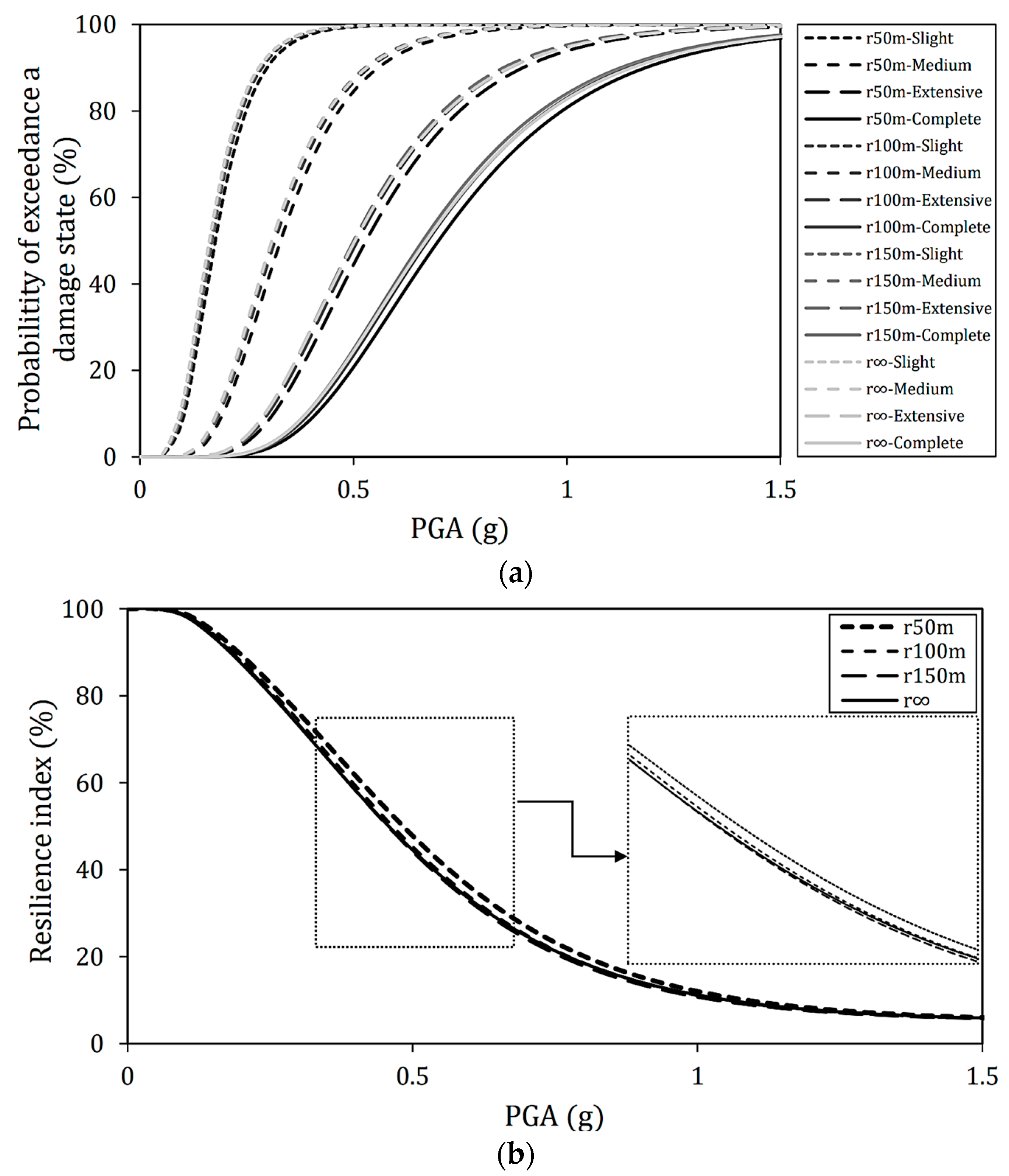
In this section, each incident angle’s resilience and fragility curve is calculated and discussed for different deck radii when long-period ground motions are applied to the target bridge model. First, the fragility curves of each deck radius with an incident angle of 0° are shown in Figure 4a. As observed from Figure 4, the degree of damage increases from the lighter side to the darker side of each line. In addition, the seismic resilience index is constructed by the mean response of the records set, as illustrated in Figure 4b.
For the long-period ground motion of PGA = 1 g, for example, slight and moderate damage occurred in all deck radii. It has also been shown that there is a 95% probability of extensive damage and an 80% or higher probability of complete damage. In all damage states, the fragility with the smallest radius of 50 m tends to be the lowest. In addition, although it is not remarkable up to a radius of 50 m, the fragility increases as the radius increases. In addition, for other radii, the fragility or vulnerability is high when the incident angle is 0°. From the results of the eigenvalue analysis, the effective modal mass ratio of the main mode in the incident angle direction is 98.72% for the straight bridge, 93.50% for the radius of 150 m, 87.32% for the radius of 100 m, and 59.96% for the radius of 50 m. In the case of a radius of 50 m, the first natural period is 0.92 s, in which the acceleration response spectrum of long-period ground motion is greatly excited. However, when the radius is 50 m, the effective mass ratio is meager, so the effective mass at resonance may be small, the displacement is small, and the fragility is reduced.
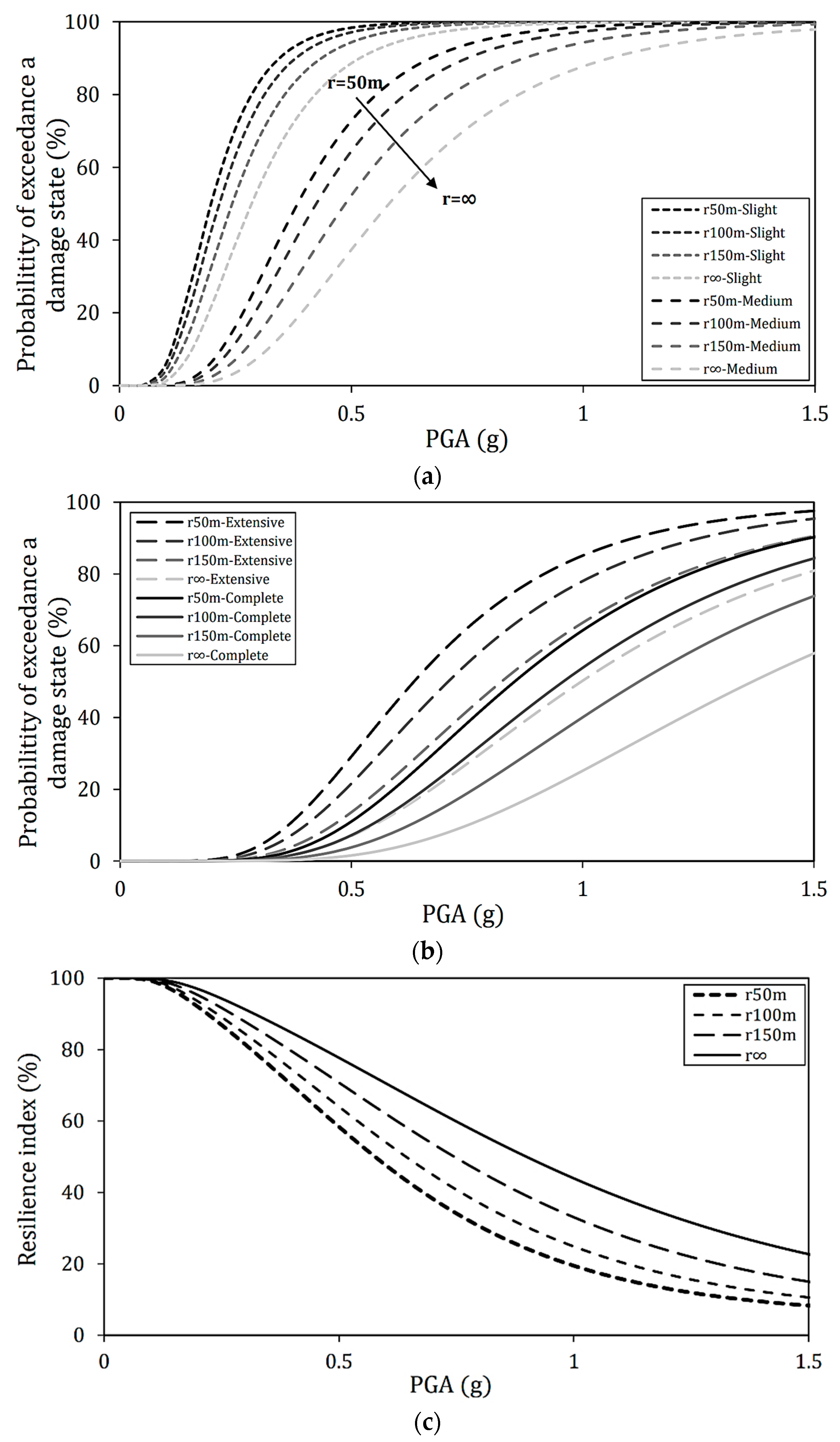
Next, Figure 5 shows the fragility and resilience curves obtained by applying long-period ground motions to the Regular bridge at an incident angle of 45°. For better comparison, unlike the case where the incident angle is 0°, the results are shown for each damage state. The change in fragility due to the radius is more remarkable than in the case of an incident angle of 0°. The results indicate that the smaller the radius, the higher the fragility. The radius of ∞ and radius of 150 m have a large effective modal mass ratio in the primary and third modes, while the radius of 100 m and the radius of 50 m are dominated by the primary and secondary modes (see Table 7). Additionally, in the case of a radius of 150 m, the secondary mode contributes, albeit slightly, and the bridge may be more vulnerable than a straight bridge.
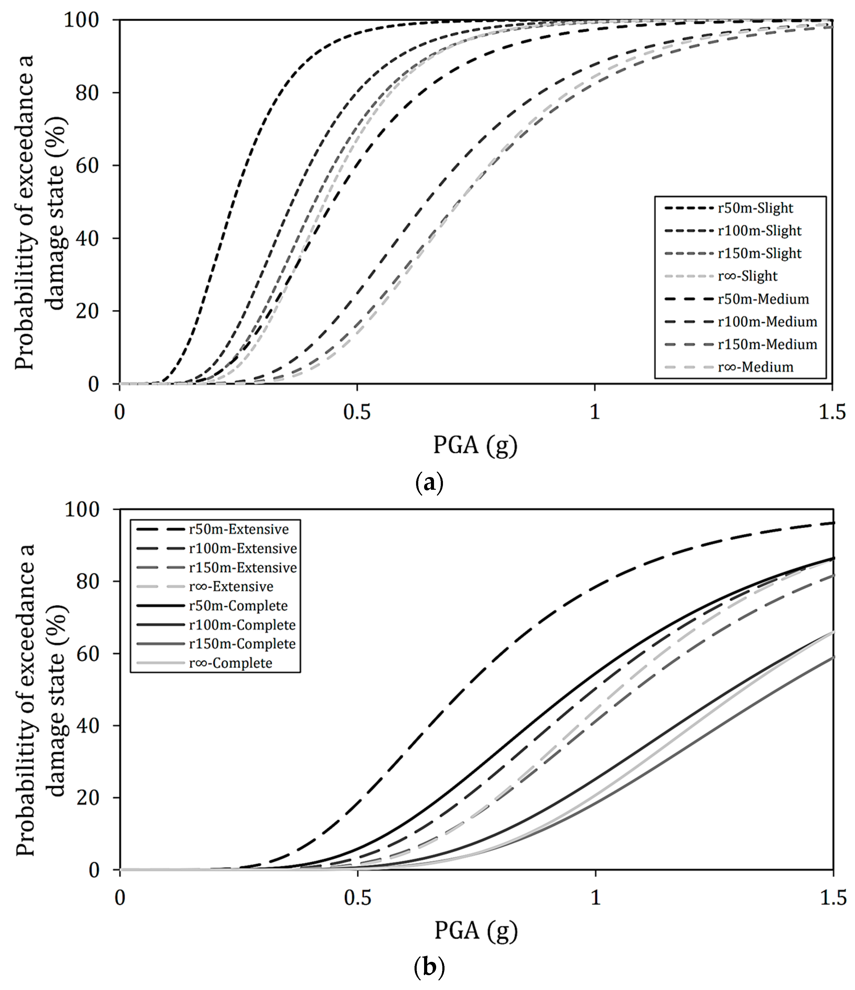
Furthermore, the analysis results when the incident angle is 90° are depicted in Figure 6a,b for each damage state in fragility curves and Figure 6c for the seismic resilience index. It can be seen that the case with a radius of 50 m is significantly different from the cases with other radii. It is considered that this is related mainly to the mode that governs the transverse behavior during an earthquake. In the case of a radius of 50 m, the effective modal mass is 89% in the secondary mode that dominates the vibration in the incident angle direction. On the other hand, at a radius of 100 m, a radius of 150 m, and a radius of ∞, the effective mass is 69%, 88%, and 96%, respectively, and the third mode dominates the vibration in the incident angle direction. Therefore, the natural periods of the main vibration modes of radius of 50 m, radius of 100 m, radius of 150 m, and radius of ∞ are 0.699, 0.638, 0.629, and 0.620 s, respectively. The radius of 50 m has a secondary mode having a longer natural period than the tertiary mode as the main mode. As a result, resonance occurred, and it became very fragile. Even with a radius of 100 m, the vulnerability was higher than the case of 150 m and ∞. Similar to the radius of 150 m and ∞, the radius of 100 m is the main vibration mode in the third mode, but the effective mass ratio of the secondary mode is also 26%. It is possible that this secondary mode contributed to the behavior of the bridge during an earthquake.

4.3. Effect of Incident Angle on Seismic Resilience Assessment

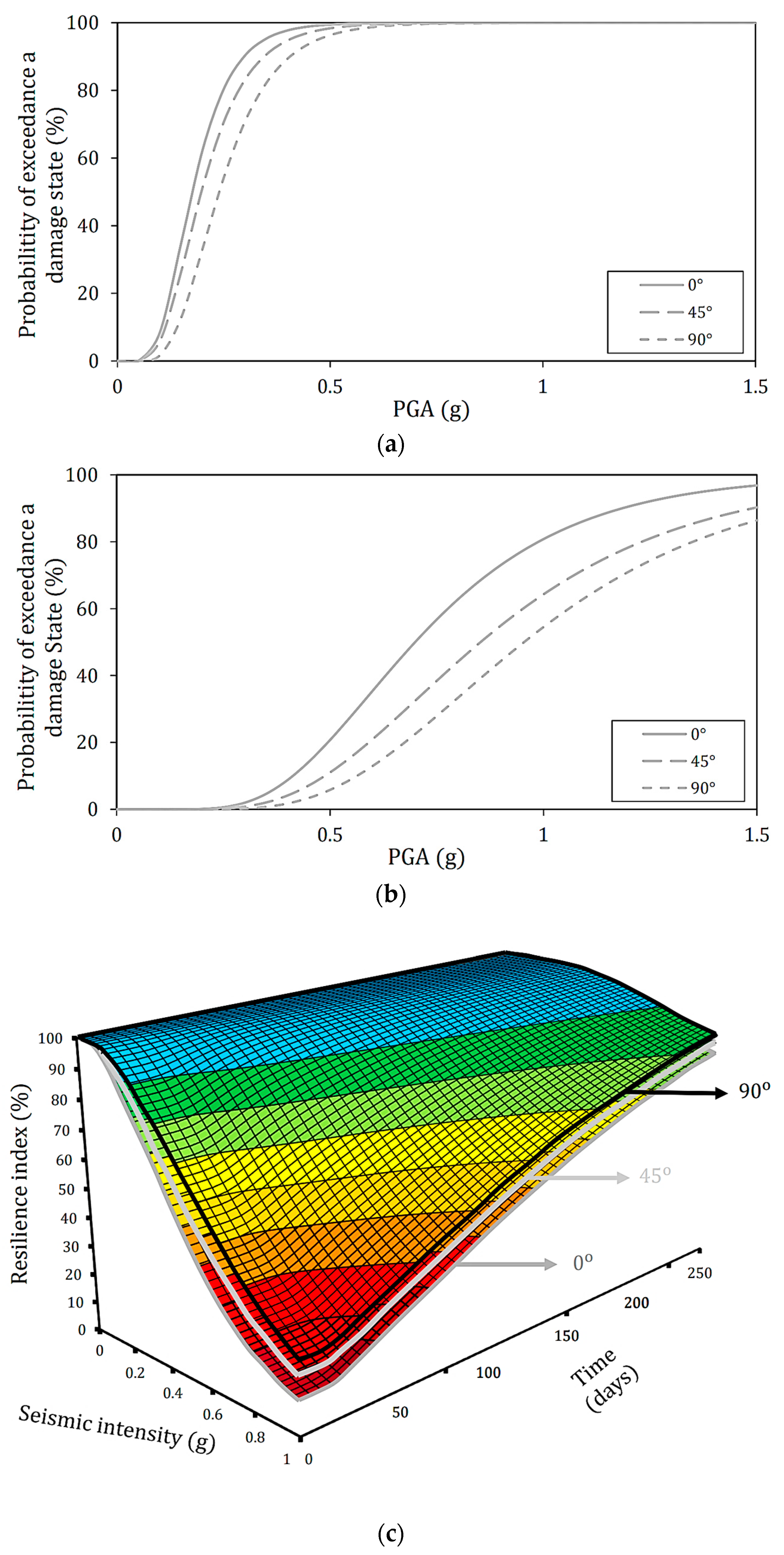
This part discusses the effect of different incidence angles on the target bridge’s seismic vulnerability. Figure 7a,b show the fragility curves when long-period ground motion is incident on a bridge with a radius of 50 m at each incident angle for each damage state. In addition, the resilience index would be considered a more comprehensible and sensible parameter for decision makers rather than fragility curves, which can be used as a decision-making index as a reference for program progress in short-, mid-, and long-term planning. For this purpose, the resilience index is evaluated in the form of a surface-based HAZUS post-event recovery path (see Table 2) [41], as shown in Figure 7c. It can be stated that for all damage states, the higher the angle of incidence, the lower the fragility. This indicates that all target bridges are most likely to resonate in the direction of the incident angle of 0°. The difference is most noticeable in the complete damage state. For the case of PGA = 1 g, for example, the probability of a complete damage state differs by about 25% between the incident angles of 0° and 90°. This indicates that the angle of incidence greatly influences the damaged state of the bridge.
As discussed so far (see Table 7), when the incident angle is 0°, the effective mass of the primary mode is about 60%, which is the main vibration mode. It should be noted that in the case of the straight bridge, the incident angle of 0° is in the direction of the bridge axis. It is known that the primary mode’s translational behavior governs the bridge’s behavior during an earthquake, and resonance may occur. On the other hand, the effective mass of the secondary mode is 44.37% at an incident angle of 45°, and the effective mass of the secondary mode is 88.73% at an incident angle of 90°, which are the main vibration modes. Therefore, when the incident angle is 0°, the mode with a long natural period becomes the main vibration mode. So, it may become fragile due to resonance with the long-period component. Furthermore, as discussed in Section 4.2, the piers can become more vulnerable if the incident angle is perpendicular to the longitudinal direction of the piers. Focusing on the case where the radius is 50 m and the incident angle is 0°, the conditions are the same for piers 2 and 3 in Figure 2. Actually, the drift ratio of piers 2 and 3 is about 1.5 times those of piers 1 and 4, which contributes to the fragility curve as the maximum drift ratio.
The main vibration mode is the secondary mode for the incident angle of 45° and 90°. However, when the incident angle is 45°: (I) in addition to the secondary mode, the effective mass of the primary mode is as large as about 30%, which may have contributed, and (II) there is a pier that the ground motion acted upon in the perpendicular direction concerning the longitudinal direction of the pier. So, a large displacement occurred partially, as in the case where the seismic motion acted in the direction of the bridge axis of the straight bridge. The vulnerability may have increased from the above two points. From the above, when dealing with piers with a longitudinal direction, such as pile bent, the angle of incidence and the effective mass may be the parameters that should be paid particular attention to.

4.4. Effect of Earthquake Period on Seismic Resilience Assessment

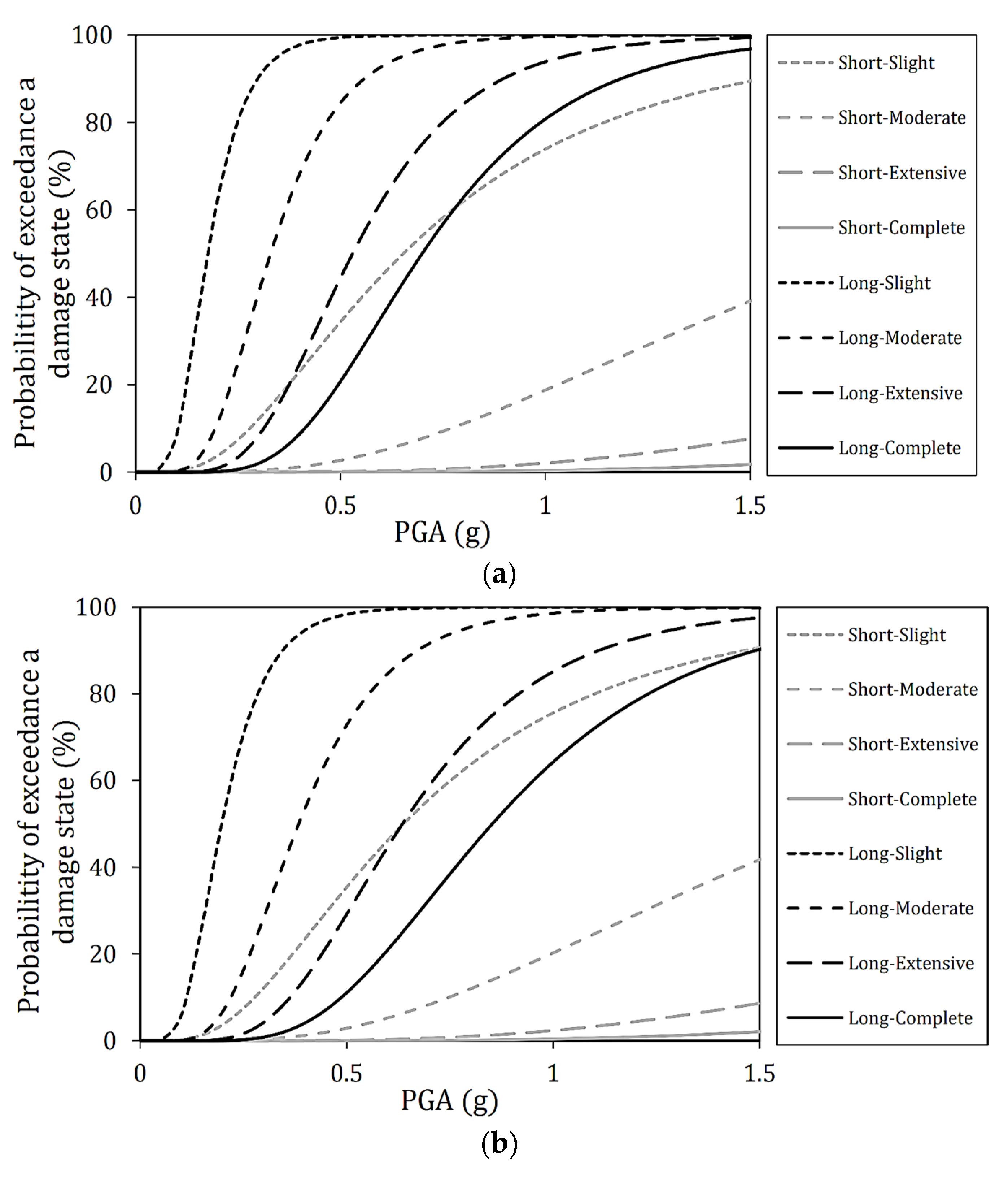
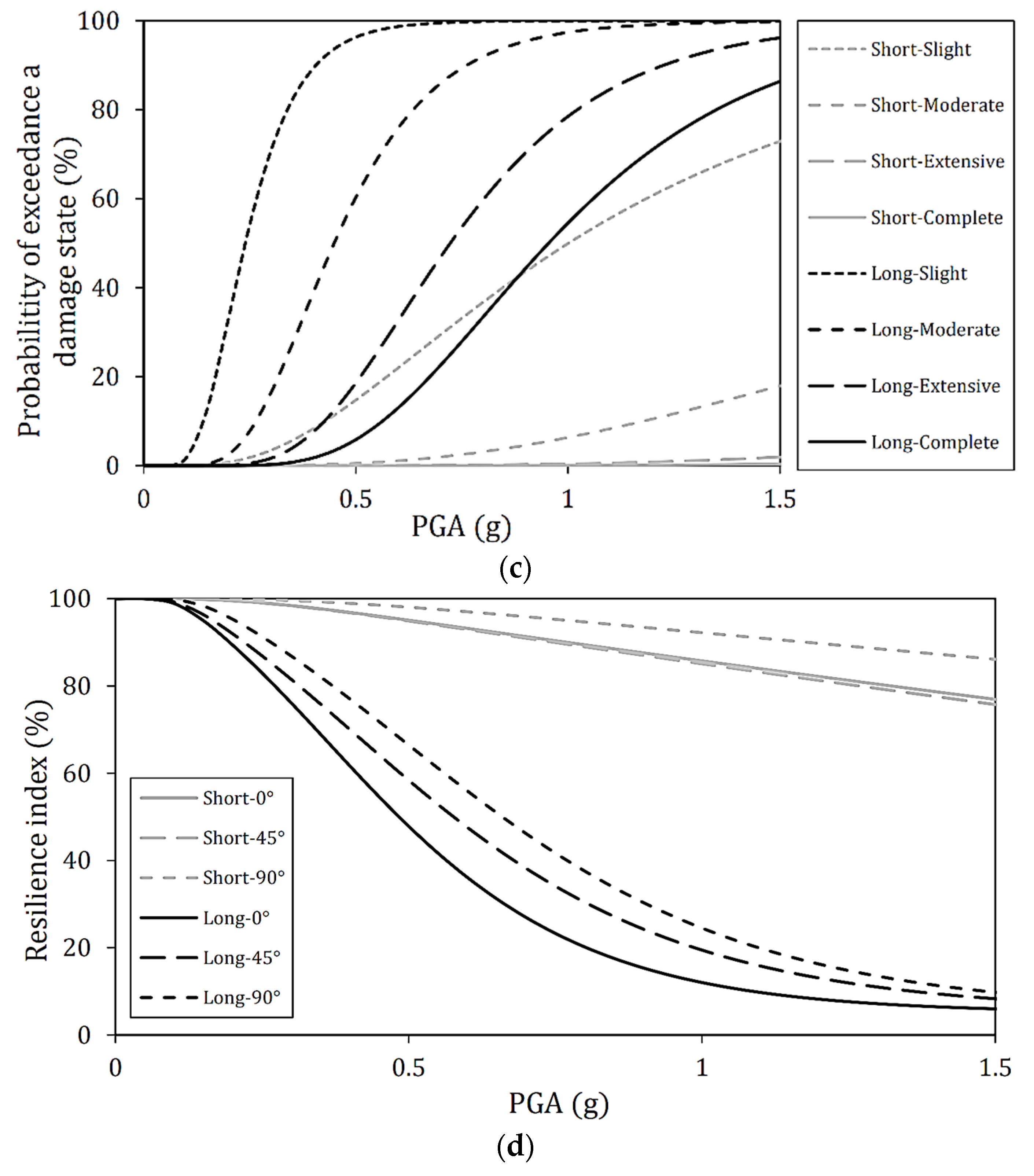
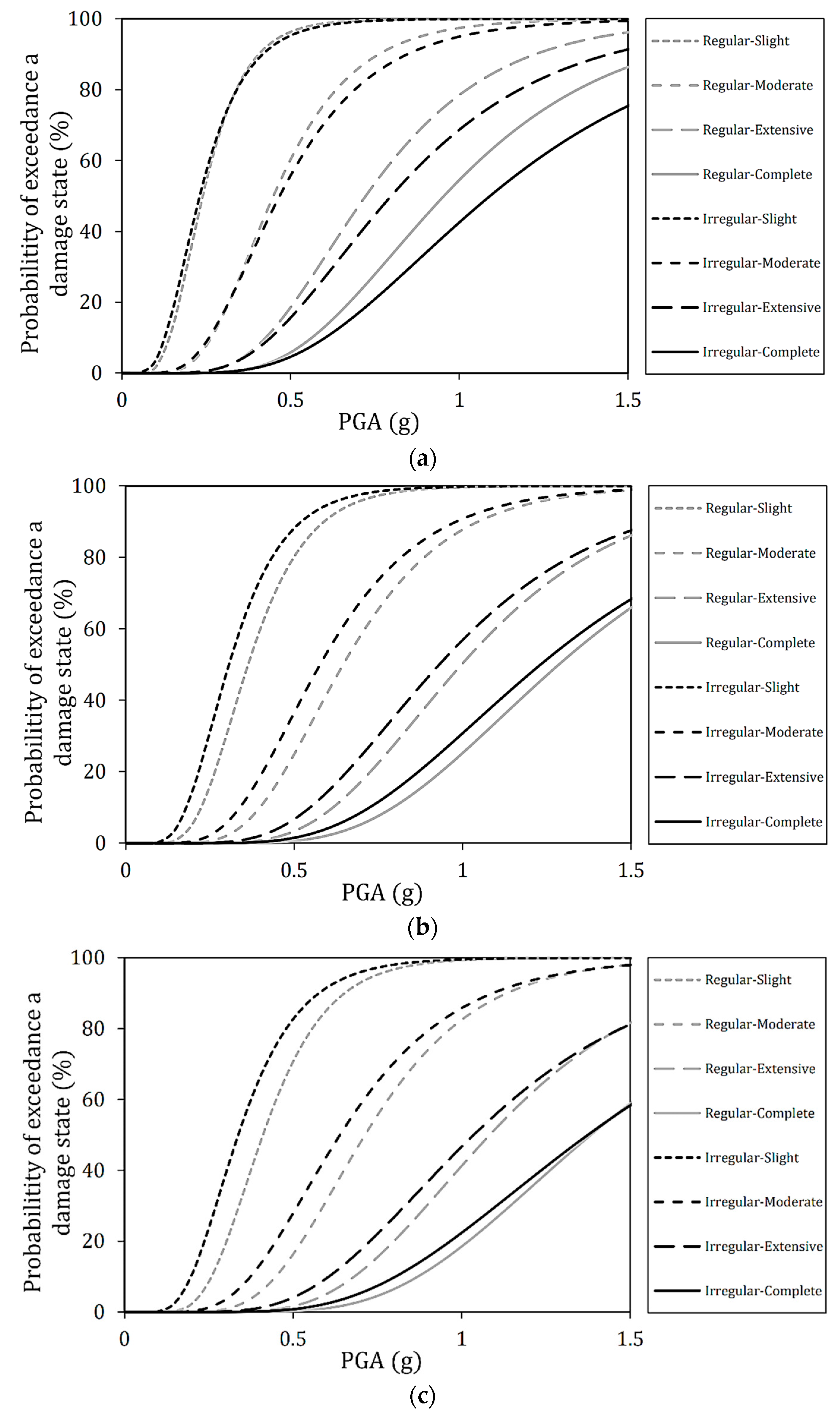
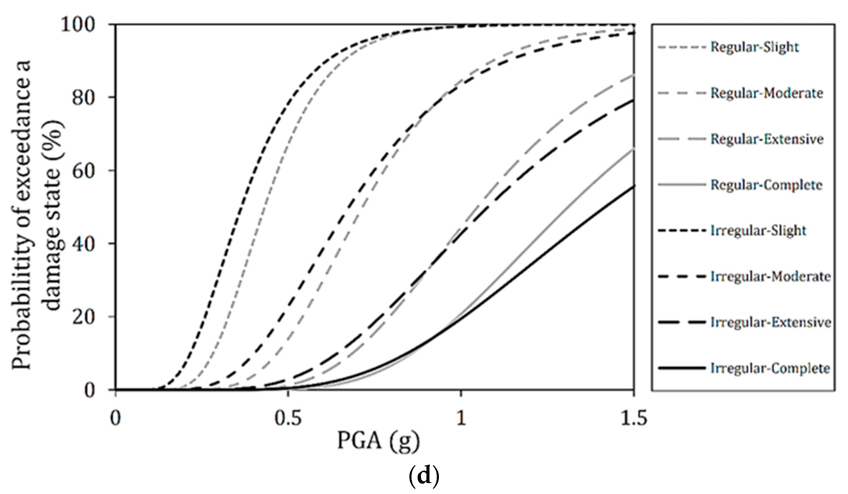
The effect of the period of ground motion on seismic fragility curves and resilience index is examined in this part. Figure 8 represents the fragility and resilience curves when long- and short-period ground motions are applied to a bridge with a radius of 50 m at incident angles of 0°, 45°, and 90°, respectively.
The bridges under study are significantly more vulnerable under long-period ground motion than under short-period ground motion. The reason for this high vulnerability is that the maximum period range of selected long-period strong motion records is the same as the main period of the bridge under study (see Figure 3); as a result, the resonance occurs. From Table 7, the natural periods in the main modes with incident angles of 0°, 45°, and 90° are 0.931, 0.699, and 0.670 s, respectively. Additionally, considering the effective mass, the fourth mode governs the vibration, and the natural period is 0.638 s. Therefore, it is thought that the vibration mode of 0.6 s or more controls the seismic behavior of the target bridge. As discussed before, the short-period ground motions are predominant in the range of 0 to 1 s, while the long-period ground motions are predominant in the range of 0.2 to 2 s. At 0.6 s or longer, the long-period ground motions are significantly more dominant than the short-period ground motions. Without exception, the fragility tended to be higher when long-period ground motion is applied than when short-period ground motion is applied, as shown in Figure 8. In addition, since the same results are obtained for other deck radii and incident angle directions, they tend to be more vulnerable to long-period ground motions than short-period ground motions. Therefore, seismic retrofitting of bridges against the long-period ground motion is vital as a countermeasure against huge earthquakes such as the Nankai Trough Earthquake.

4.5. Effect of Pier Height Irregularity on Seismic Resilience Assessment

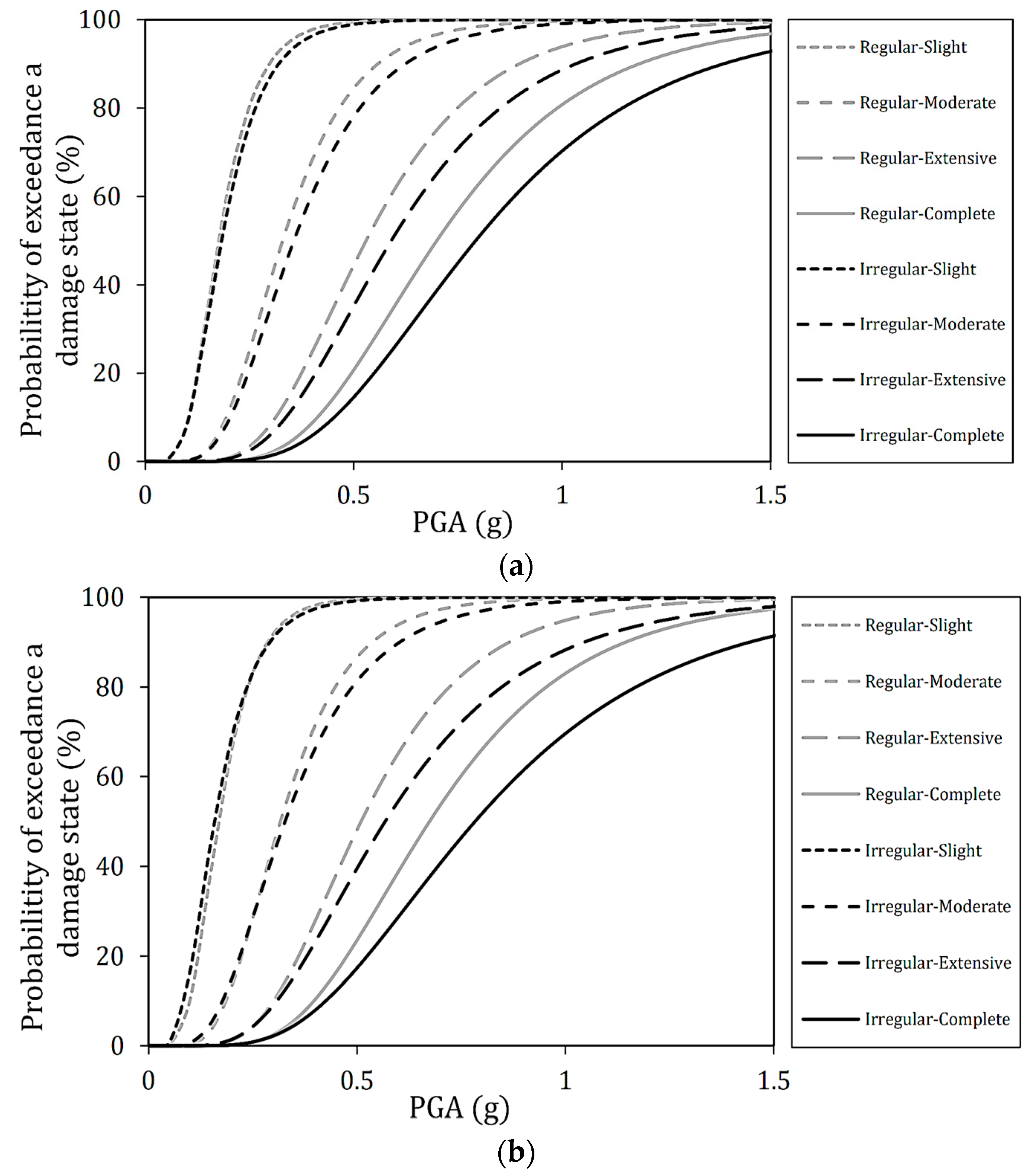
This section examines the effect of pier irregularities on bridges’ seismic fragility and resilience. First, the changes in bridge fragility due to pier height irregularities when long-period ground motions are applied at an incident angle of 0° are shown in Figure 9 for each deck radius. Pier height irregularities have little effect at all deck radii where the damage is slight. The irregular bridge’s seismic behavior can be almost the same as that of the Regular bridge, while the PGA is small. However, it can be seen that the fragility curve and resilience index of the Irregular bridge gradually deviate from the fragility curve of the Regular bridge as the damage state worsens, such as moderate, extensive, and complete. Following Table 7, the natural period and effective mass of Regular and Irregular bridges are compared. Each main mode is the first mode, the natural period of the Regular bridge is 0.931 s, and the effective mass is about 60%. On the other hand, the natural period of the Irregular bridge is 1.056 s, and the effective mass is 64%. Since long-period ground motion is used as ground motion input, it is generally expected that Irregular bridges with longer natural periods will be more vulnerable than Regular bridges in each damage state. However, the Regular bridge became more vulnerable.
However, the result is that the Irregular bridge is less vulnerable than the Regular bridge. The irregularity in the piers’ height can be considered a factor for this fact. As shown in Figure 2, the Irregular bridge consists of higher (1, 4) and shorter piers (2, 3). As a result of non-linear time history analysis, piers 1 and 4 had the same drift ratio, while piers 2 and 3 had the same drift ratio. The maximum drift ratio occurred in all cases at shorter piers. However, it is possible that the higher pier constrained the horizontal displacement of the upper end of the shorter pier, making it less fragile than expected from the natural period and effective mass ratio. Furthermore, the Irregular bridge is equivalent to the regular one when the PGA is small. The results indicate that the larger the PGA, the less vulnerable or more resilient it is than the Regular bridge. In other words, even if the seismic intensity increases, Irregular bridges may be less vulnerable than Regular bridges.
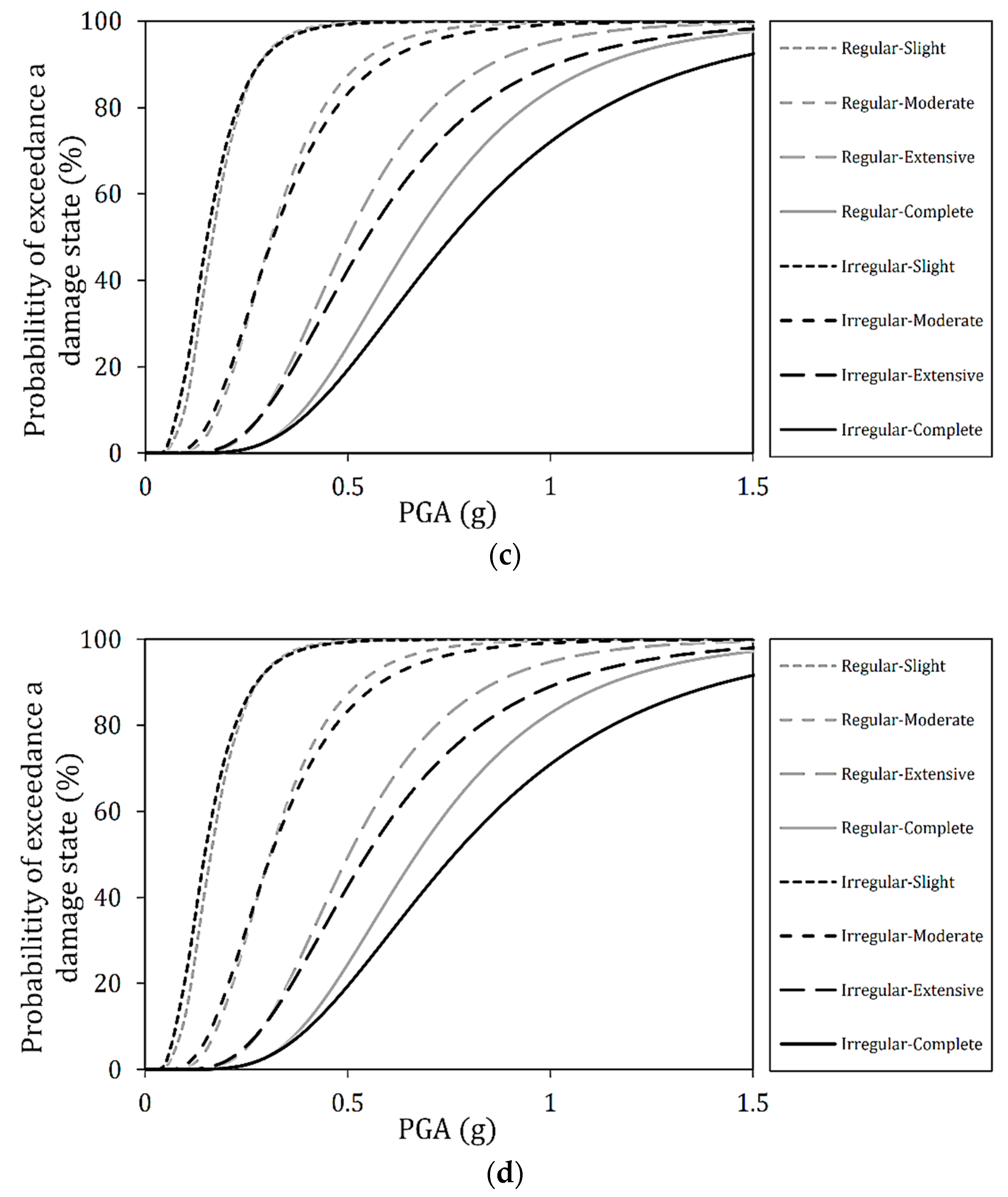
Focusing on extensive and complete damage, the difference between a Regular bridge and an Irregular bridge is more remarkable between straight and curved bridges. Therefore, the difference in deck radius may affect the seismic resistance due to the difference in the irregularity of the piers. Second, the fragility curves’ change due to the piers’ irregularity when the incident angle is 90° is shown in Figure 10, for each deck radius.
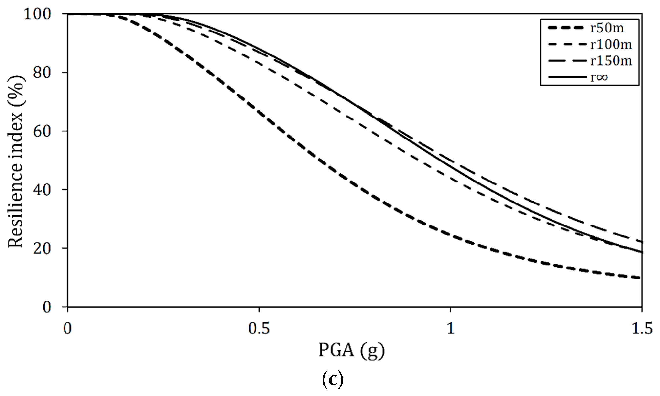
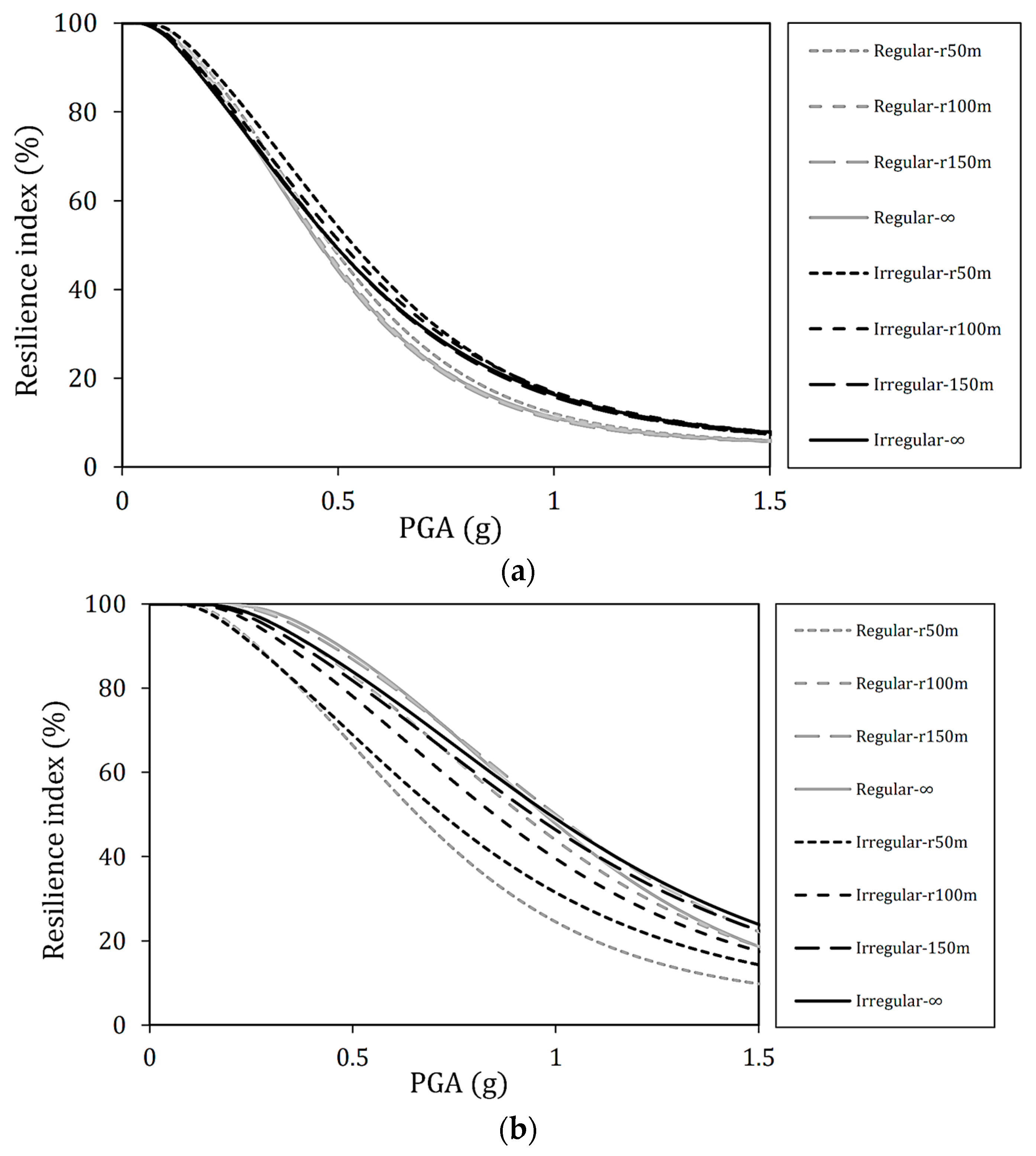
For better understanding, the seismic resilience index of the bridges under study due to pier height irregularities when long-period ground motions are applied at an incident angle of 0° and 90° is shown in Figure 11 for each deck radius. In this regard, the median and log-standard deviation values of the interpolated log-normal distribution functions for system resilience right after a seismic hazard event with different intensity levels are presented in Table 8.
As a general trend, it can be confirmed that the Irregular bridge is less likely to become more vulnerable as the PGA increases than the Regular bridge, such as at the incident angle of 0°. As a result, this trend becomes more pronounced as the deck radius increases, especially in the case of straight bridges. Irregular bridges are more likely to experience slight damage than Regular bridges, while Regular bridges are more likely to reach a complete damage state. It is considered that the effective mass ratio is significantly related (see Table 7). In this respect, only when the radius is 50 m is the main mode the first mode when the incident angle is 90° for both the Regular and Irregular bridges. On the other hand, in other radii of the deck, higher modes may contribute more to the seismic behavior of Irregular bridges rather than Regular bridges, and as a result it causes an increase in displacement and fragility values. In addition, the increase in the median of resilience log-normal distribution function that can be achieved by different situations is given in Table 9. In this table, the percentage increase is fitted as exponential functions based on the ratios of the considered incident seismic wave angle for different situations.

5. Conclusions

Curved reinforced concrete bridges are commonly used in urban areas such as highway interchange bridges and transportation hubs. Bridges are known as one of the most key implementations of transportation networks which have essential roles in different activities such as economics, logistics, emergency medical services, emergency routes for firefighting, and rescue operations on highways and in urban areas. In addition, these bridges have complicated dynamic characteristics because of their irregular geometry and non-uniform mass and stiffness distributions that make them highly vulnerable to earthquake events. Therefore, their functionality is a vital matter for decision makers and their future planning to have a sustainable society. In this regard, this study aims to evaluate the typical curved reinforced concrete bridges with circular cross-section piers in consideration of parameters including (1) deck radius (50, 100, 150 m, and infinity), (2) pier height irregularity (Regular and Irregular bridge cases), and (3) incident seismic wave angle (0°, 45°, and 90°) subjected to short- and long-period ground motions. Firstly, fragility curves are calculated by performing non-linear time history incremental dynamic analyses and based on probabilistic seismic demand models for each case. Next, seismic resilience curves/surfaces are constructed, and values of the log-normal distribution function are presented for assessing system resilience. The results are discussed mainly using the seismic fragility and resilience curves/surfaces obtained from the relationship between the seismic intensity level and the maximum drift ratio. In addition, the effect of the ground motion period on the seismic vulnerability of the bridge under study due to the difference in each parameter is also examined.
Specific results obtained from this research are as follows:
  • Effect of deck radius on seismic vulnerability: under long-period ground motions with an incident angle of 0°, the first mode excited in the earthquake motion’s direction is the main mode. Therefore, since the natural periods of straight and curved bridges are almost the same, the behavior during earthquakes is nearly equivalent. However, as the radius becomes smaller, the fragility decreases slightly, and displacement may differ depending on the magnitude of the effective mass. In addition, when the incident angle becomes more significant, such as 45° and 90°, the main mode transforms to the secondary or third modes; hence, the effective mass ratio and the main mode vary. For this reason, it is considered that the fragility was reduced compared to the incident angle of 0°, and the effect of the deck radius on the seismic vulnerability and resilience index became more remarkable. Furthermore, it is confirmed that the fragility may increase when ground motion is incident perpendicular to the longitudinal direction of the piers.
  • Effect of pier height irregularity on seismic vulnerability: the results indicate that Irregular bridges are less likely to become vulnerable as the intensity measurements increase compared to Regular bridges. This is thought to be due to the nature of seismic energy being dissipated by short piers, similar to previous studies on short-period ground motion. Unlike Regular bridges, which consist only of short piers, Irregular bridges may be less vulnerable or more resilient because the shorter piers restrict the displacement of the higher piers.
  • Effect of ground motion period on seismic vulnerability, deck radius, and angle of incidence: reinforced concrete bridges generally have a natural period of 0.5 to 1.5 s. In this respect, the results show that even if the seismic intensity level is such that slight damage occurs under short-period ground motions, more severe damage may occur under long-period ground motions. In addition, when long-period ground motions are applied compared to short-period ground motions, the vulnerability of the bridge under study increased due to the difference in deck radius and incident angle. Since the natural period of the target bridge is within the range where the long-period ground motion is predominant, it is possible that it responds more sensitively to changes in parameters. In addition, irregularities tend to differ between long-period ground motion and short-period ground motion.
Finally, it should be noted that aging is another significant parameter for seismic resilience assessment of bridges. In future work, this effect should also be considered in seismic fragility studies.

Author Contributions

Conceptualization, P.O., R.C.G., M.M. and N.K.; methodology, T.U., P.O., R.C.G. and N.K.; software, T.U. and P.O.; validation, T.U., P.O. and N.K.; formal analysis, T.U. and P.O.; investigation, T.U. and P.O.; resources, T.U., P.O. and N.K.; data curation, T.U. and P.O.; writing—original draft preparation, T.U. and P.O.; writing—review and editing, P.O., R.C.G., M.M. and N.K.; visualization, T.U. and P.O.; supervision, R.C.G. and N.K.; project administration, R.C.G. and N.K. All authors have read and agreed to the published version of the manuscript.

Funding

This research received no external funding.

Institutional Review Board Statement

Not applicable.

Informed Consent Statement

Not applicable.

Data Availability Statement

Not applicable.

Acknowledgments

The authors appreciate the generous support of Kenichiro Nakarai and Ichiro Ario during this research study.

Conflicts of Interest

The authors declare no conflict of interest.

Appendix A

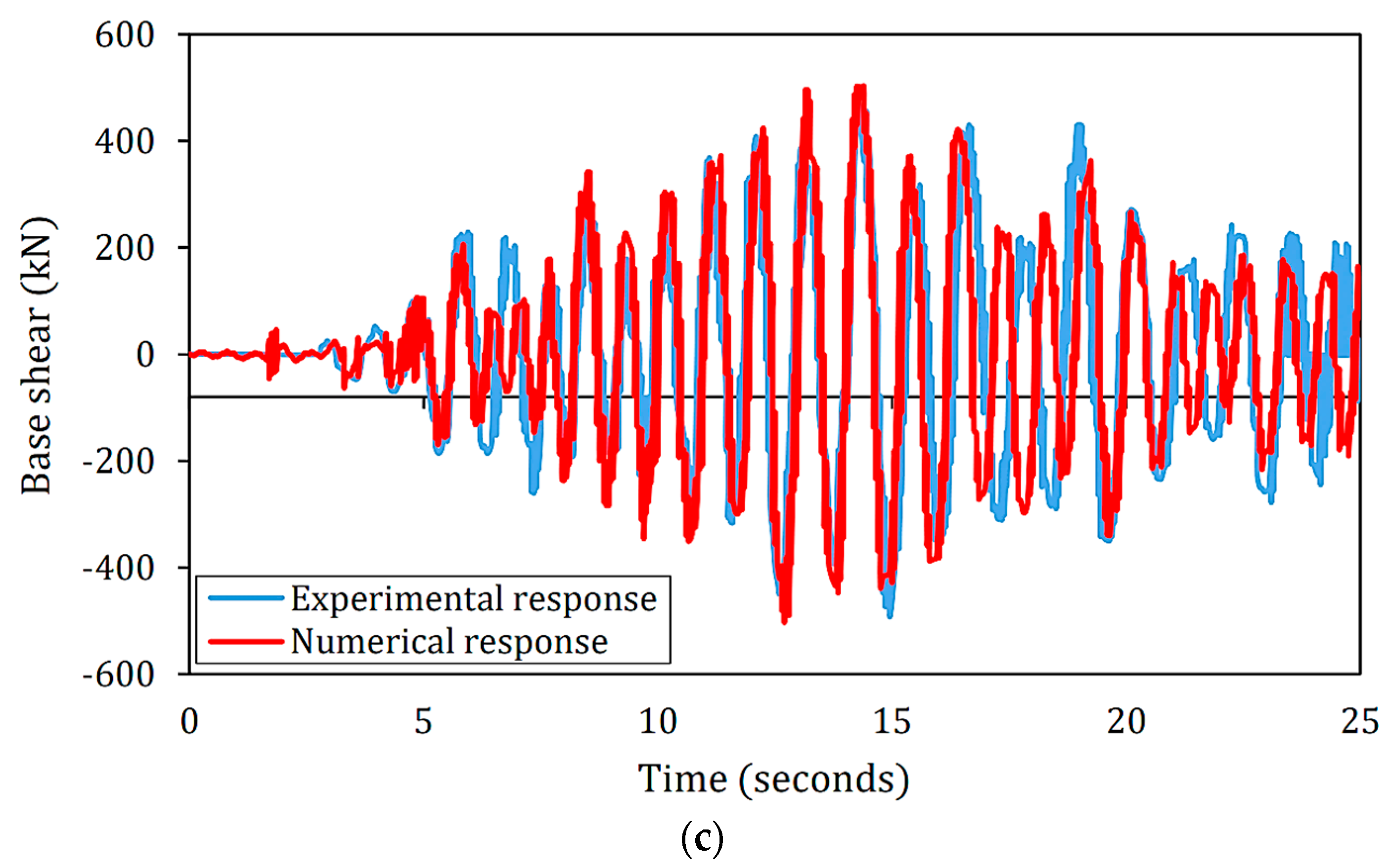
To check the accuracy and reliability of the obtained results from the modeling conducted by SeismoStruct software [46], a non-linear time-history analysis is achieved to evaluate the response of a real reinforced concrete bridge pier under one uniaxial earthquake ground motion. The research conducted by Bianchi et al. [60] is used for verification, where further information about the geometry, material properties, and the tests performed can be found. Figure A1a in Appendix A shows the real model installed on the shaking table. Figure A1b,c represent a comparison between the top displacement and base shear responses of the structure modeled by the finite element method and the response of the structure on the shaking table experiment, respectively. As shown in this diagram, very close agreement between numerically predicted and experimentally measured top displacement and base shear time histories is achieved.
Figure A1. General view of (a) full-scale reinforced concrete bridge pier tested [60], numerical and experimental (b) top frame displacement, and (c) base shear caused by the seismic record used in Reference [60].
Sustainability 15 07764 g0a1aSustainability 15 07764 g0a1b

References

  1. Mehrjoo, M.; Khaji, N.; Moharrami, H.; Bahreininejad, A. Damage detection of truss bridge joints using artificial neural networks. Expert Syst. Appl. 2008, 35, 1122–1131. [Google Scholar] [CrossRef]
  2. Ahmadi, H.R.; Daneshjoo, F.; Khaji, N. New damage indices and algorithm based on square time–frequency distribution for damage detection in concrete piers of railroad bridges. Struct. Control Health Monit. 2015, 22, 91–106. [Google Scholar] [CrossRef]
  3. Naghshineh, A.; Tehrani, F.M.; Fischer, O. Application of sustainable concrete in the seismic evaluation of an innovative type of buckling restrained brace. Sustainability 2022, 14, 16344. [Google Scholar] [CrossRef]
  4. An, W.; Zhou, L.; Kang, M.; Yang, H.; Mo, L. Failure mode analysis of bridge pier due to eccentric impact based on separation of pier and beam. Sustainability 2023, 15, 1435. [Google Scholar] [CrossRef]
  5. Fu, Z.; Wu, D.; Fang, L.; Chen, D.; Ji, B. Influence factors and repair effects of seismic damage to a box section steel pier. J. Earthq. Tsunami 2019, 13, 1940001. [Google Scholar] [CrossRef]
  6. Shekari, M.R.; Khaji, N.; Ahmadi, M.T. On the seismic behavior of cylindrical base-isolated liquid storage tanks excited by long-period ground motions. Soil Dyn. Earthq. Eng. 2010, 30, 968–980. [Google Scholar] [CrossRef]
  7. Liu, L.; Yang, X.; Yan, B.; Miao, S. Dynamic responses of RC girder bridge under heavy truck and seismic loads combined. Sustainability 2022, 14, 9263. [Google Scholar] [CrossRef]
  8. Kanamori, H. A semi-empirical approach to prediction of long-period ground motions from great earthquakes. Bull. Seismol. Soc. Am. 1979, 69, 1645–1670. [Google Scholar] [CrossRef]
  9. Guo, W.; Li, J.; Xiang, N. Seismic performance of the buckling-restrained brace central buckle for long-span suspension bridges. J. Earthq. Tsunami 2018, 12, 1850015. [Google Scholar] [CrossRef]
  10. Mahmood, K.; Rehman, Z.; Farooq, K.; Memon, S.A. One dimensional equivalent linear ground response analysis—A case study of collapsed Margalla Tower in Islamabad during 2005 Muzaffarabad Earthquake. J. Appl. Geophys. 2016, 130, 110–117. [Google Scholar] [CrossRef]
  11. Mahmood, K.; Zamin, B.; Igbal, S.; Rehman, Z.; Afzal, S.; Safdar, M.; Igbal, Q.; Ali, A. Local site effect on seismic hazard of the relocated new Balakot town. Soil Dyn. Earthq. Eng. 2022, 162, 107451. [Google Scholar] [CrossRef]
  12. Koketsu, K.; Miyake, H. A seismological overview of long-period ground motion. J. Seismol. 2008, 12, 133–143. [Google Scholar] [CrossRef]
  13. Choi, E.; DesRoches, R.; Nielson, B. Seismic fragility of typical bridges in moderate seismic zones. Eng. Struct. 2004, 26, 187–199. [Google Scholar] [CrossRef]
  14. Yi, J.; Li, J.; Guan, Z. Shake table studies on viscous dampers in seismic control of a single-tower cable-stayed bridge model under near-field ground motions. J. Earthq. Tsunami 2018, 12, 1850011. [Google Scholar] [CrossRef]
  15. Ma, H.B.; Zhuo, W.D.; Lavorato, D.; Nuti, C.; Fiorentino, G.; Marano, G.C.; Greco, R.; Briseghella, B. Probabilistic seismic response and uncertainty analysis of continuous bridges under near-fault ground motions. Front. Struct. Civ. Eng. 2019, 13, 1510–1519. [Google Scholar] [CrossRef]
  16. Zhao, Y.; Hu, H.; Bai, L.; Tang, M.; Chen, H.; Su, D. Fragility analyses of bridge structures using the logarithmic piecewise function-Based probabilistic seismic demand model. Sustainability 2021, 13, 7814. [Google Scholar] [CrossRef]
  17. Gong, C.; Kang, L.; Liu, L.; Lei, M.; Ding, W.; Yang, Z. A novel prediction model of packing density for single and hybrid steel fiber-aggregate mixtures. Powder Technol. 2023, 418, 118295. [Google Scholar] [CrossRef]
  18. Okazawa, S.; Tsumori, T.; Yamashita, T.; Tanaka, S. Finite element seismic response analysis of a reinforced concrete pier with a fractured fine tetrahedron mesh. J. Earthq. Tsunami 2016, 10, 1640013. [Google Scholar] [CrossRef]
  19. Dezfuli, F.H.; Alam, M.S. Effect of different steel-reinforced elastomeric isolators on the seismic fragility of a highway bridge. Struct. Control Health Monit. 2017, 24, e1866. [Google Scholar] [CrossRef]
  20. Mao, J.; Jia, D.; Yang, Z.; Xiang, N. Seismic performance of concrete bridge piers reinforced with hybrid shape memory alloy (SMA) and steel bars. J. Earthq. Tsunami 2020, 14, 2050001. [Google Scholar] [CrossRef]
  21. Román, Á.F.G.; Khan, M.S.A.; Kabir, G.; Billah, M.; Dutta, S. Evaluation of interaction between bridge infrastructure resilience factors against seismic hazard. Sustainability 2022, 14, 10277. [Google Scholar] [CrossRef]
  22. Tondini, N.; Stojadinovic, B. Probabilistic seismic demand model for curved reinforced concrete bridges. Bull. Earthq. Eng. 2012, 10, 1455–1479. [Google Scholar] [CrossRef]
  23. Amirihormozaki, E.; Pekcan, G.; Itani, A. Analytical fragility functions for horizontally curved steel I-girder highway bridges. Earthq. Spectra 2015, 31, 2235–2254. [Google Scholar] [CrossRef]
  24. Gupta, T.; Sandhu, D. Seismic response of horizontally curved bridges in combination with skewed abutments. Structures 2022, 36, 846–878. [Google Scholar] [CrossRef]
  25. Liu, X.; Li, J.; Tsang, H.H.; Wilson, J.L. Evaluating self-centering behavior of unbonded prestressed bridge columns using a new performance index based on quasi-static analysis. J. Earthq. Tsunami 2018, 12, 1850001. [Google Scholar] [CrossRef]
  26. Tehrani, F.M. Deploying and rating sustainable practices for resilient bridge infrastructure. In Proceedings of the Fifth International Conference on Bridges, Tehran, Iran, 17–18 December 2019; AUT: Tehran, Iran, 2019. Paper MS05. [Google Scholar]
  27. Liu, J.; Cheng, H.; Liu, Q.; Wang, H.; Bu, J. Research on the damage diagnosis model algorithm of cable-stayed bridges based on data mining. Sustainability 2023, 15, 2347. [Google Scholar] [CrossRef]
  28. Abbasi, M.; Zakeri, B.; Amiri, G.G. Probabilistic seismic assessment of multiframe concrete box-girder bridges with unequal-height piers. J. Perform. Constr. Facil. 2015, 30, 04015016. [Google Scholar] [CrossRef]
  29. Tamaddon, S.; Hosseini, M.; Vasseghi, A. The effect of curvature angle of curved RC box-girder continuous bridges on their transient response and vertical pounding subjected to near-source earthquakes. Structures 2020, 28, 1019–1034. [Google Scholar] [CrossRef]
  30. Yamamoto, H.; Shimizu, T.; Iwamoto, M.; Umehara, H. Effect of long-period ground motion on long-period concrete structures. Annu. Proc. Concr. Eng. 2007, 29, 829–834. (In Japanese) [Google Scholar]
  31. Tomi, K.; Fujita, K.; Itoyama, Y.; Umehara, H. Seismic response analysis of multi-span continuous viaduct under long-period seismic motion. Annu. Proc. Concr. Eng. 2007, 29, 817–822. (In Japanese) [Google Scholar]
  32. Todorov, B.; Billah, A.H.M.M. Seismic fragility and damage assessment of reinforced concrete bridge pier under long-duration, near-fault, and far-field ground motions. Structures 2021, 31, 671–685. [Google Scholar] [CrossRef]
  33. Peng, T.; Guan, J.; Wu, Y. Numerical and experimental investigation of the seismic effect of a two-stage seismic isolation method. Sustainability 2023, 15, 4883. [Google Scholar] [CrossRef]
  34. Omidian, P.; Khaji, N. A multi-objective optimization framework for seismic resilience enhancement of typical existing RC buildings. J. Build. Eng. 2022, 52, 104361. [Google Scholar] [CrossRef]
  35. Padgett, J.E.; DesRoches, R. Methodology for the development of analytical fragility curves for retrofitted bridges. Earthq. Eng. Struct. Dyn. 2008, 37, 1157–1174. [Google Scholar] [CrossRef]
  36. Billah, A.H.M.M.; Alam, M.S.; Bhuiyan, M.A.R. Fragility analysis of retrofitted multicolumn bridge bent subjected to near-fault and far-field ground motion. J. Bridge Eng. 2013, 18, 992–1004. [Google Scholar] [CrossRef]
  37. Billah, A.H.M.M.; Alam, M.S. Seismic fragility assessment of highway bridges: A state-of-the-art review. Struct. Infrastruct. Eng. 2015, 11, 804–832. [Google Scholar] [CrossRef]
  38. Kia, M.; Amini, A.; Bayat, M.; Ziehl, P. Probabilistic seismic demand analysis of structures using reliability approaches. J. Earthq. Tsunami 2021, 15, 2150011. [Google Scholar] [CrossRef]
  39. Vamvatsikos, D.; Cornell, C.A. Incremental dynamic analysis. Earthq. Eng. Struct. Dyn. 2002, 31, 491–514. [Google Scholar] [CrossRef]
  40. Soleimani, F.; Hajializadeh, D. State-of-the-art review on probabilistic seismic demand models of bridges: Machine-learning application. Infrastructures 2022, 7, 64. [Google Scholar] [CrossRef]
  41. HAZUS–MH MR5. Multi-Hazard Loss Estimation Methodology–Earthquake Model; Department of Homeland Security: Washington, DC, USA, 2014.
  42. Tehrani, F.M.; Nazari, M.; Naghshineh, A. Role of seismic isolation and protection devices in enhancing structural resilience. In Objective Resilience, Book 3: Technology; ASCE Press: Reston, VA, USA, 2022. [Google Scholar]
  43. Tehrani, F.M.; Nelson, D. From sustainability to resilience: A practical guide to ENVISION®. In Objective Resilience, Book 2: Objective Processes; Ettouney, M., Ed.; ASCE Press: Reston, VA, USA, 2022. [Google Scholar]
  44. Cimellaro, G.P.; Reinhorn, A.M.; Bruneau, M. Framework for analytical quantification of disaster resilience. Eng. Struct. 2010, 32, 3639–3649. [Google Scholar] [CrossRef]
  45. Huff, T. Partial isolation as a design alternative for pile bent bridges in the New Madrid seismic zone. Pract. Period. Struct. Des. 2016, 21, 04015018. [Google Scholar] [CrossRef]
  46. AASHTO. American Association of State Highway and Transportation Officials (AASHTO) Guide Specifications for LRFD Seismic Bridge Design; AASHTO: Washington, DC, USA, 2011. [Google Scholar]
  47. SeismoStruct. SeismoSoft, a Computer Program for Static and Dynamic Nonlinear Analysis of Framed Structures; SeismoStruct: Miki, Japan, 2023. [Google Scholar]
  48. Madas, P.; Elnashai, A.S. A new passive confinement model for transient analysis of reinforced concrete structures. Earthq. Eng. Struct. Dyn. 1992, 21, 409–431. [Google Scholar] [CrossRef]
  49. Mander, J.B.; Priestley, M.J.N.; Park, R. Theoretical stress–strain model for confined concrete. J. Struct. Eng. 1988, 114, 1804–1826. [Google Scholar] [CrossRef]
  50. Martinez-Rueda, J.E.; Elnashai, A.S. Confined concrete model under cyclic load. Mater Struct. 1997, 30, 139–147. [Google Scholar] [CrossRef]
  51. Yassin, M.H.N. Nonlinear Analysis of Prestressed Concrete Structures under Monotonic and Cyclic Loads. Ph.D. Thesis, University of California, Berkeley, CA, USA, 1994. [Google Scholar]
  52. Menegotto, M.; Pinto, P.E. Method of Analysis for Cyclically Loaded R.C. Plane Frames including Changes in Geometry and Non-Elastic Behaviour of Elements under Combined Normal Force and Bending, Symposium on the Resistance and Ultimate Deformability of Structures Acted on by Well Defined Repeated Loads; International Association for Bridge and Structural Engineering: Zurich, Switzerland, 1973; pp. 15–22. [Google Scholar]
  53. Filippou, F.C.; Popov, E.P.; Bertero, V.V. Effects of Bond Deterioration on Hysteretic Behaviour of Reinforced Concrete Joints; Report EERC 83-19; Earthquake Engineering Research Center, University of California: Berkeley, CA, USA, 1983. [Google Scholar]
  54. Monti, G.; Nuti, C.; Santini, S. CYRUS—Cyclic Response of Upgraded Sections; Report No. 96-2; University of Chieti: Chieti, Italy, 1996. [Google Scholar]
  55. Fragiadakis, M.; Pinho, R.; Antoniou, S. Modelling Inelastic Buckling of Reinforcing Bars under Earthquake Loading, in Progress in Computational Dynamics and Earthquake Engineering; Papadrakakis, M., Charmpis, D., Lagaros, N., Tsompanakis, Y., Balkema, A., Eds.; Taylor & Francis: Leiden, The Netherlands, 2008. [Google Scholar]
  56. Abdel Raheem, E.A. Exploring seismic response of bridges with bidirectional coupled modelling of base isolation bearings system. Arab. J. Sci. Eng. 2014, 39, 8669–8679. [Google Scholar] [CrossRef]
  57. Shome, N.; Cornel, C.A. Probabilistic Seismic Demand Analysis of Nonlinear Structures, Reliability of Marine Structures Program Technical Report RMS-35; Stanford Digital Repository: Tokyo, Japan, 1999. [Google Scholar]
  58. PEER. Pacific Earthquake Engineering Research Center (PEER) Online Strong Motion Database; PEER: Berkeley, CA, USA, 2023. [Google Scholar]
  59. Zhou, Y.; Ping, T.; Gong, S.; Zhu, Y. An improved defining parameter for long-period ground motions with application of a super-tall building. Soil Dyn. Earthq. Eng. 2018, 113, 462–472. [Google Scholar] [CrossRef]
  60. Bianchi, F.; Sousa, R.; Pinho, R. Blind prediction of a full-scale RC bridge column tested under dynamic conditions. In Proceedings of the 3rd International Conference on Computational Methods in Structural Dynamics and Earthquake Engineering, COMPDYN, Corfu, Greece, 25–28 May 2011. Paper no. 294. [Google Scholar]
Figure 1. An overall picture of the seismic resilience assessment process of this study.
Sustainability 15 07764 g001
Figure 2. The schematic of the bridge under study with various considered configuration parameters.
Sustainability 15 07764 g002
Figure 3. Scaled acceleration response spectrum used in this study for (a) short-period and (b) long-period ground motions.
Sustainability 15 07764 g003
Figure 4. Seismic assessment of different deck radii under long-period ground motions with incident angle of 0° in terms of (a) fragility curves and (b) resilience curves.
Sustainability 15 07764 g004
Figure 5. Seismic assessment of different deck radii under long-period ground motions with incident angle of 45° in terms of (a) slight and moderate and (b) extensive and complete damage states and (c) resilience curves.
Sustainability 15 07764 g005
Figure 6. Seismic assessment of different deck radii under long-period ground motions with incident angle of 90° in terms of (a) slight and moderate and (b) extensive and complete damage states and (c) resilience.
Sustainability 15 07764 g006aSustainability 15 07764 g006b
Figure 7. Seismic assessment of different incident angles under long-period ground motions at radius of 50 m in terms of (a) slight and (b) complete damage state and (c) resilience surfaces.
Sustainability 15 07764 g007
Figure 8. Comparison of short- and long-period ground motion results at radius of 50 m and under incident angle of (a) 0°, (b) 45°, (c) 90° for fragility curves and (d) resilience curves.
Sustainability 15 07764 g008aSustainability 15 07764 g008b
Figure 9. Comparison of the fragility curves of pier height irregularities under incident angle of 0° at radius of (a) 50 m, (b) 100 m, (c) 150 m, and (d) ∞.
Sustainability 15 07764 g009aSustainability 15 07764 g009b
Figure 10. Comparison of the fragility curves of pier height irregularities under incident angle of 90° at radius of (a) 50 m, (b) 100 m, (c) 150 m, and (d) ∞.
Sustainability 15 07764 g010aSustainability 15 07764 g010b
Figure 11. Comparison of the resilience curves of pier height irregularities with different radii at incident angle of (a) 0° and (b) 90°.
Sustainability 15 07764 g011
Table 1. Definitions of abbreviations and acronyms used in the present document.
Abbreviations/SymbolsDefinition
DIDamage Index
DS/LSDamage State/Limit State
TREElapsed time to recover the infrastructure
EDPEngineering Demand Parameter
EEvent
P E . Exceedance probability for a damage/limit state
H · Heaviside step functions
IDAIncremental Dynamic Analysis
IMIntensity Measurement
Tii-th period value of record response spectrum
LRBLaminated Rubber Bearing
σ k Log-normal standard deviation
L . Loss function
μ k Median log-normal
PGAPeak Ground Acceleration
f r e c Post-event recovery path
PSDMProbabilistic Seismic Demand Model
R t Resilience index
Q t System performance function
Table 2. Damage states and their explanation (adopted based on HAZUS [41]).
Damage StatesDescriptionFragility Curves in Drift
μ k 1
Restoration Curves in Days,
Mean   ( σ k )
SlightSmall cracks and peels on the abutment, cracks in the shear keys on the abutment, small peels on the hinges, small peels on the columns, or small cracks on the deck, etc.0.010.6 (0.6)
ModerateModerate shear cracking and peeling (structurally sound as a column), widespread cracking and peeling of shear keys, etc.0.0252.5 (2.7)
ExtensiveShear failure of columns (structurally unsafe condition), large residual displacement at connections, breakage of shear keys at abutments, etc.0.0575 (42)
CompleteDefined by the collapse of columns and loss of bearing support, the collapse of decks, and the tilting of substructures due to foundation breakage.0.075230 (110)
1 Note: log-normal standard deviations ( σ k ) are assumed to be equal to 0.6 for each damage state.
Table 3. Material properties used for bridge modeling.
MaterialMechanical PropertyValue
ConcreteCompressive strength (MPa)30
Tensile strength (MPa)3
Strain at peak stress (%)0.2
Modulus of elasticity (GPa)25.7
Specific weight (kN/m3)24
Steel (bar)Modulus of elasticity (GPa)200
Yield strength (MPa)525
Strain hardening parameters (%)0.5
Specific weight (kN/m3)78
Table 4. The main steps of selection of records according to Zhou et al. [59].
Start
Data base input: Pacific Seismic Engineering Research Center (PEER) database.
While ( t < t i ) do ( t i   is the number of considered (20) short- or long-period ground motions)
Step 1—Set main formulation:   β l = T i 0.6 β a T i T i 0.6
Step 2—The response spectrum must first be scaled: This means that the PGA of the original
record must be scaled to 1 g, and then response spectrum obtained.
Step 3—Calculate   T i ^0.6:   T i is the i-th period point (within the period range of [0, 10] s with
interval of 0.01 s).
Step 4—Calculate ( T i ^ 0.6 ) β a T i :  β a T i is the normalized acceleration response spectrum value of the ground motions.
Step 5—Calculate   β l : Calculate the summations using the main formula (Step 1) to obtain β l .
Step 6—Check main conditions:
β l 0.4 0.4 < β l < 0.6 0.6 β l N o r m a l   g r o u n d   m o t i o n s M e d i u m l o n g p e r i o d   g r o u n d   m o t i o n s L o n g p e r i o d   g r o u n d   m o t i o n s
End while
Return the best set of records (short- or long-period ground motion)
End
Table 5. Short-period ground motion list chosen in this research.
No.RSNDirectionEpicenter (km)YearEarthquake Name β l
12115EW190.092002Denali, Alaska0.3741
22115NS190.092002Denali, Alaska0.3614
36015EW197.732010El Mayor-Cucapah0.3956
46015NS197.732010El Mayor-Cucapah0.3377
56048EW278.582010El Mayor-Cucapah0.3837
66048NS278.582010El Mayor-Cucapah0.2990
76968EW281.892010Darfield, New Zealand0.1784
86968NS281.892010Darfield, New Zealand0.1935
96976EW108.932010Darfield, New Zealand0.3406
106976NS108.932010Darfield, New Zealand0.2921
111103EW196.181995Kobe, Japan0.2479
121103NS196.181995Kobe, Japan0.2455
131745EW101.421992Little Skull Mtn, NV0.0629
141745NS101.421992Little Skull Mtn, NV0.0752
152953EW104.841999Chi-Chi, Taiwan-050.2573
162953NS104.841999Chi-Chi, Taiwan-050.1482
173862EW108.501999Chi-Chi (aftershock 4), Taiwan0.1936
183862NS108.501999Chi-Chi (aftershock 4), Taiwan0.3073
195456EW145.222008Iwate0.2009
205456NS145.222008Iwate0.2268
Table 6. Long-period ground motion list chosen in this research.
No.RSNDirectionEpicenter (km)YearEarthquake Name β l
11156EW311.501999Kocaeli, Turkey0.8970
21156NS311.501999Kocaeli, Turkey0.6124
32102EW296.112002Denali, Alaska0.6373
42102NS296.112002Denali, Alaska0.6185
53789EW183.891999Hector Mine0.7819
63789NS183.891999Hector Mine0.7074
75858EW176.892008El Mayor-Cucapah0.8067
85858NS176.892008El Mayor-Cucapah0.6276
96987EW261.392010Darfield, New Zealand0.6177
106987NS261.392010Darfield, New Zealand0.7137
112059EW275.022002Nenana Mountain, Alaska0.8345
122059NS275.022002Nenana Mountain, Alaska0.7218
133791EW304.732003San Simeon, CA1.6710
143791NS304.732003San Simeon, CA1.4591
154900EW300.232007Chuetsu-oki0.6506
164900NS300.232007Chuetsu-oki0.7369
176130EW308.512000Tottori, Japan0.8772
186130NS308.512000Tottori, Japan0.8422
198489EW332.002010El Mayor-Cucapah1.1992
208489NS332.002010El Mayor-Cucapah1.0083
Table 7. The first five natural periods and effective modal mass ratios (corresponding to the longitudinal direction) of the bridges under study.
Bridge
Type
Moder 50mr 100mr 150mr ∞
Period (s)Effective Modal Mass (%)Period (s)Effective Modal Mass (%)Period (s)Effective Modal Mass (%)Period (s)Effective Modal Mass (%)
45°90°45°90°45°90°45°90°
Regular bridge10.93159.9629.970.000.92387.3243.290.000.92193.5046.750.000.91998.7249.360.00
20.6990.0044.3788.730.6520.0040.5326.510.6460.003.917.590.6410.000.000.00
30.6700.003.917.810.6380.009.3569.480.6290.0044.2688.400.6200.0047.9795.94
40.63832.2116.110.000.62011.043.670.000.6175.222.440.000.6150.000.000.00
50.5975.622.800.000.5830.190.080.000.5800.000.000.000.5780.140.070.00
Irregular bridge11.05663.5631.780.001.04288.6743.840.001.03894.2147.100.001.03598.8649.430.00
20.7780.0047.3194.590.7280.0051.5395.240.7160.0048.3996.050.7060.0048.6097.20
30.73434.8117.400.000.71310.332.060.000.7094.752.020.000.7050.000.000.00
40.6710.001.452.900.6480.000.672.060.6450.000.601.200.6420.000.000.00
50.6020.330.160.000.5850.0580.020.000.5810.180.090.000.5790.330.160.00
Table 8. Log-normally distributed functions for resilience estimation right after a seismic hazard event based on the incident angle of 0°.
Radius50 m100 m150 m
Situation
Long-periodRegular 100 % L N 0.48 , 0.65 1 100 % L N ( 0.46 , 0.65 ) 100 % L N ( 0.45 , 0.65 ) 100 % L N ( 0.53 , 0.65 )
Irregular 100 % L N 0.52 , 0.70 100 % L N ( 0.53 , 0.76 ) 100 % L N ( 0.48 , 0.75 ) 100 % L N ( 0.48 , 0.75 )
Short-periodRegular 100 % L N 3.30 , 1.10 100 % L N ( 3.30 , 1.10 ) 100 % L N ( 3.20 , 1.10 ) 100 % L N ( 3.30 , 1.10 )
Irregular 100 % L N 3.40 , 1.10 100 % L N ( 2.50 , 1.05 ) 100 % L N ( 2.20 , 0.99 ) 100 % L N ( 2.10 , 0.97 )
1 Note: L N ( μ , σ ) refers to log-normal distribution with parameters μ and σ , which are the mean (in PGA) and standard deviation of the corresponding distribution, respectively.
Table 9. Predictive exponential functions of logistic regression for quantifying the percentage increase in median of resilience log-normal distribution for long-period ground motions.
SituationRatio 150 m100 m150 m
Regular I i / I 1 9.926 e 0.636 I i 14.28 e 0.951 I i 32.87 e 0.638 I i 80.57 e 0.171 I i
Irregular 0.107 e 2.891 I i 0.053 e 3.584 I i 5.602 e 1.408 I i 12.287 e 1.059 I i
1 Note: where I i 2 , 3 is the incident seismic wave angle category (2–3 represent 45° and 90°).
Disclaimer/Publisher’s Note: The statements, opinions and data contained in all publications are solely those of the individual author(s) and contributor(s) and not of MDPI and/or the editor(s). MDPI and/or the editor(s) disclaim responsibility for any injury to people or property resulting from any ideas, methods, instructions or products referred to in the content.