Article

Distributed Control Algorithm for DC Microgrid Using Higher-Order Multi-Agent System

by
Muhammad Ahsan
1,*,
Jose Rodriguez
2 and
Mohamed Abdelrahem
3,4,*
1
Department of Measurements and Control Systems, Silesian University of Technology, 44-100 Gliwice, Poland
2
Faculty of Engineering, Universidad San Sebastián, Recoleta, Santiago 4080871, Chile
3
Department of Electrical Engineering, Faculty of Engineering, Assiut University, Assiut 71516, Egypt
4
Chair of High-Power Converter Systems (HLU), Technical University of Munich (TUM), 80333 Munich, Germany
*
Authors to whom correspondence should be addressed.
Sustainability 2023, 15(10), 8336; https://doi.org/10.3390/su15108336
Submission received: 12 April 2023 / Revised: 12 May 2023 / Accepted: 19 May 2023 / Published: 20 May 2023

Abstract

:
During the last decade, DC microgrids have been extensively researched due to their simple structure compared to AC microgrids and increased penetration of DC loads in modern power networks. The DC microgrids consist of three main components, that is, distributed generation units (DGU), distributed non-linear load, and interconnected power lines. The main control tasks in DC microgrids are voltage stability at the point of common coupling (PCC) and current sharing among distributed loads. This paper proposes a distributed control algorithm using the higher-order multi-agent system for DC microgrids. The proposed control algorithm uses communication links between distributed multi-agents to acquire information about the neighbors’ agents and perform the desired control actions to achieve voltage balance and current sharing among distributed DC loads and DGUs. In this research work, non-linear ZIP loads and dynamical RLC lines are considered to construct the model. The dynamical model of the power lines and DGU are used to construct the control objective for each distributed DGU that is improved using the multi-agent system-based distributed current control. The closed-loop stability analysis is performed at the equilibrium points, and control gains are derived. Finally, simulations are performed using MATLAB/Simulink environment to verify the performance of the proposed control method.

1. Introduction

In the modern power system renewable energy sources and new loads are extensively used as the result of technological advancements and environmental policies [1,2]. On the one hand, renewable energy sources provide clean energy to clients at low cost, while, on the other hand, renewable energy sources are uncontrollable, and the energy produced by these sources depends on environmental conditions, and, hence, are considered as uncertain of generation side, as well as the uncertainty of load side. Traditionally, controllable power generations have been adjusted to track uncontrollable loads in power networks. In modern power networks, renewable energy sources are increasing exponentially and, therefore, the demand for new control strategies and management mechanisms is also increasing [3,4]. To establish advanced control strategies and management mechanisms, new smart sensors and communication networks are introduced in the modern power system. Sustainability is a critical aspect of the design and operation of DC microgrids. It involves ensuring that the microgrid’s energy supply and demand are balanced over the long term while considering the social, economic, and environmental impacts. A sustainable DC microgrid must be designed to maximize energy efficiency, minimize carbon emissions, and reduce reliance on fossil fuels. It should also be resilient to disruptions, adaptable to changing energy demands, and provide equitable access to energy services.
Microgrids are made up of scattered distributed generation units (DGUs), such as photovoltaic (PV) panels, wind and gas turbines, biomass and fuel cells, as well as energy storage devices, such as batteries, supercapacitors, flywheels, and controllable loads, to provide the local network operator with significant control capabilities [5,6,7]. These systems can be linked to the distribution network, but may also operate in an isolated mode if the main network fails [8]. Microgrids, which are compatible with AC and DC operating standards, have been shown to have several benefits, such as improved power quality, lower transmission losses, and the capacity to operate in grid-connected and islanded modes [9]. DC microgrids are ideal for sources with direct current output, such as PVs, fuel cells, batteries, and supercapacitors. Furthermore, when loads in the system are supplied with DC power, conversion losses from sources to loads are lower than in AC microgrids. Inverters are required for DC output type sources, gas engine cogeneration, and wind turbines to convert DC to AC power to match output voltages and frequencies to those of utility grids [10]. In addition to reducing losses in AC/DC conversions, DC microgrids provide continuous high-quality electricity when the voltage of the utility grid collapses or blackouts strike. Distributed controller for DC microgrid is proposed in [11] with multiple operating modes and a photovoltaic energy storage system is used to provide DC power without interruption. DC power supplies, for example, are widely utilized in telecommunication facilities and Internet data centers where high-quality power is required [12]. With the advancement of technology and research, power converters and power storage devices are becoming more efficient and reliable for advanced DC loads and electronics; which leads the demand for DC microgrids to new heights [13,14].
In the islanded DC microgrids, voltage instability causes critical issues in the power networks and can damage connected loads due to a sudden rise or drop in DC voltage at the point of common coupling (PCC). Therefore, voltage stability is the crucial goal in islanded DC microgrids where multiple DGUs could be connected to the DC microgrid at the PCC [14]. The error signal is built using the desired reference voltage and DC voltage at PCC, and then a primary voltage controller is constructed to minimize the error signal. To design the primary voltage control in the PCC, different control approaches are presented in the literature, such as plug-and-play control and droop control [15,16,17].
An appropriate control approach is critical in power networks in order to produce an optimum power exchange within the system and maintain suitable standards of power requirements. Distributed controllers play a crucial role in ensuring the sustainability of DC microgrids. These controllers enable the microgrid to operate autonomously, with each component making decisions based on local information. By distributing the control functions across the microgrid’s components, the system can respond quickly to changes in energy supply and demand, improve energy efficiency, and reduce energy losses. In the literature, different control strategies are proposed for microgrids [7,9,10,13,14,16,18]. These control strategies include control of power system elements and quantities, such as different sorts of power converters control and current, voltage, and frequency control. The distributed nature of microgrids forms a multi-agent system (MAS) in which each area is considered an agent that interacts with its neighboring areas to form a complex network [19,20]. Each agent consists of DGUs, storage devices, and loads. Furthermore, depending on the nature of the agent, the dynamical model of the complex system could be a first-order or higher-order network [21]. The distributed controller for these MASs solves the consensus problem that solves the problem of current sharing among the attached loads in the area, as well as the problem of voltage balance in the PCC of the DC microgrid [19,22].
Furthermore, multiple loads at PCC possess different current ratings and hence required desirable current sharing to the microgrid loads. DGU could fail due to overload if loads are not distributed among generators. Moreover, the boundedness of the sum of weighted voltages at the PCC is also required to achieve voltage balancing and is often sought to complement current sharing. The primary controller can only be applied to track the desired voltage in the PCC and cannot achieve the aforementioned goals. Therefore, secondary controllers of higher levels are required to achieve the desired goals in DC microgrids [16,18].
Ref. [23] reviews the architectures of AC, DC, and AC–DC microgrids and hierarchical control techniques that include primary, secondary, and tertiary control layers. Centralized control methods are unsuitable for large distributed networks because of their limitations in network topology [24], while this problem is overcome in decentralized control methods with DGU plug-in and plug-out and without compromising the stability of the overall system [25,26]. In [27,28], consensus-based distributed controllers using the MAS are proposed, but static power lines and ideal voltage generators with a first-order system are considered. In [29], power lines are replaced by the RL lines, and in [30] a robust distributed controller is proposed, but a suitable initialization of the controller is needed. To top it all, the above-mentioned controllers are limited to linear loads. The paper suggests a new distributed control algorithm for DC microgrids that addresses the limitations mentioned earlier. This algorithm employs a higher-order MAS and solves both the voltage balancing and current sharing issues by utilizing the secondary controller of the MAS network. Furthermore, the algorithm effectively handles the non-linear ZIP load.
The contributions and novelty of this paper are as follows:
  • The dynamical model for the higher-order MAS is constructed by employing the DGU dynamics interfaced with the Buck converter, non-linear ZIP load, and dynamical RLC lines. The power consumption of the non-linear ZIP load depends on the voltage in the PCC. This combination of DC microgrid dynamics is unique.
  • Communication networks gather information from neighboring agents and generate the consensus variable. This consensus variable is used to design the distributed controller to achieve voltage balance and current sharing among distributed non-linear ZIP loads and DGUs. The proposed distributed controller only uses the available state information of its neighboring agents.
  • Steady-state stability for the DC microgrid is investigated, and necessary conditions are derived for the uniqueness of the equilibrium point. Furthermore, closed-loop stability is derived to verify the performance of the distributed control using a higher-order MAS, and conditions on control gains are presented.
Moreover, a simulation study is performed using MATLAB/Simulink environment to verify the performance of the proposed method.
The rest of the paper is organized as follows. In Section 2, the DC microgrids are represented with the help of graph theory. The distributed nature of DC microgrids is well established using distributed power networks and communication networks. In Section 3, voltage and current control are presented using the higher-order MAS. In Section 4, closed-loop stability is performed and necessary conditions and control gains are derived. In Section 5, MATLAB/Simulink environment is used to perform the simulation study, and results are presented. Finally, in Section 6, the conclusion of the paper is presented.

2. Graph Theory for DC Microgrids

This section presents the basic notions for graph theory, which plays an important role in the communication network for distributed MASs [20]. Communication graphs could be directed or undirected based on the flow of information within the graph. A communication graph is represented with G for n number of a MAS for a specific communication topology. A directed communication graph G = ( V , E , W ) consists of a vertex set V ( G ) = { v 1 , v 2 , v 3 , v n } , an edge set E ( G ) ( v i , v j ) : v i , v j V ( G ) , and a weight set W ( G ) = ( w i j ) n × n associated with each vertex in the communication network. For each edge ( v i , v j ) , the information flows from the agent i to j, and, therefore, v i is called the parent vertex of the v j vertex and v j called the child vertex of v i . An edge is called a self-loop if information flows to the same vertex. All agents which share their information with agent i are called neighbors and are represented by N i = { j : ( i , j ) E ( G ) or ( j , i ) E ( G ) } .
The adjacency matrix A = ( A i j ) n × n of the graph G = ( V , E ) is represented by:
A i j = w i j ( i , j ) E ( G ) 0 otherwise ;
where w i j represents the weight of the edge ( i , j ) . If there exists a communication link from vertex v i to vertex v j then w i j > 0 otherwise w i j = 0 . If there is no self-loop, then w i i = 0 for i = 1 , 2 , 3 , , n . For a directed graph A i j > 0 , there exists at least one direct path from vertex v i to vertex v j , such that there exists a sequence of vertices ( v i , v i 1 ) , ( v i 1 , v i 2 ) , , ( v i l , v j ) with distinct vertices v i k , k = 1 , 2 , 3 , , l ; and if there exists a path from every vertex to every other vertex, then the graph is called directed and strongly connected. An undirected graph is a special case of a directed graph that occurs when A i j = A j i > 0 ; otherwise, A i j = A j i = 0 , where i j ; i , j = 1 , 2 , 3 , , n . The degree matrix D = ( D i j ) n × n is a diagonal matrix that consists of the degree number of all vertices and is given as follows:
D i j = i j w i j i = j 0 otherwise ;
Laplacian matrix L = ( L i j ) n × n = D A is defined by:
L i j = i j w i j i = j w i j ( i , j ) E ( G ) 0 otherwise ;
The Laplacian matrix L = ( L i j ) n × n for an undirected and connected graph of n number of agents is symmetric positive definite and the degree matrix consists of non-negative real numbers represented by diagonal elements D = diag { d 1 , d 2 , d 3 , , d n } . Figure 1 illustrates the directed and undirected communication graphs for multi-agent systems.
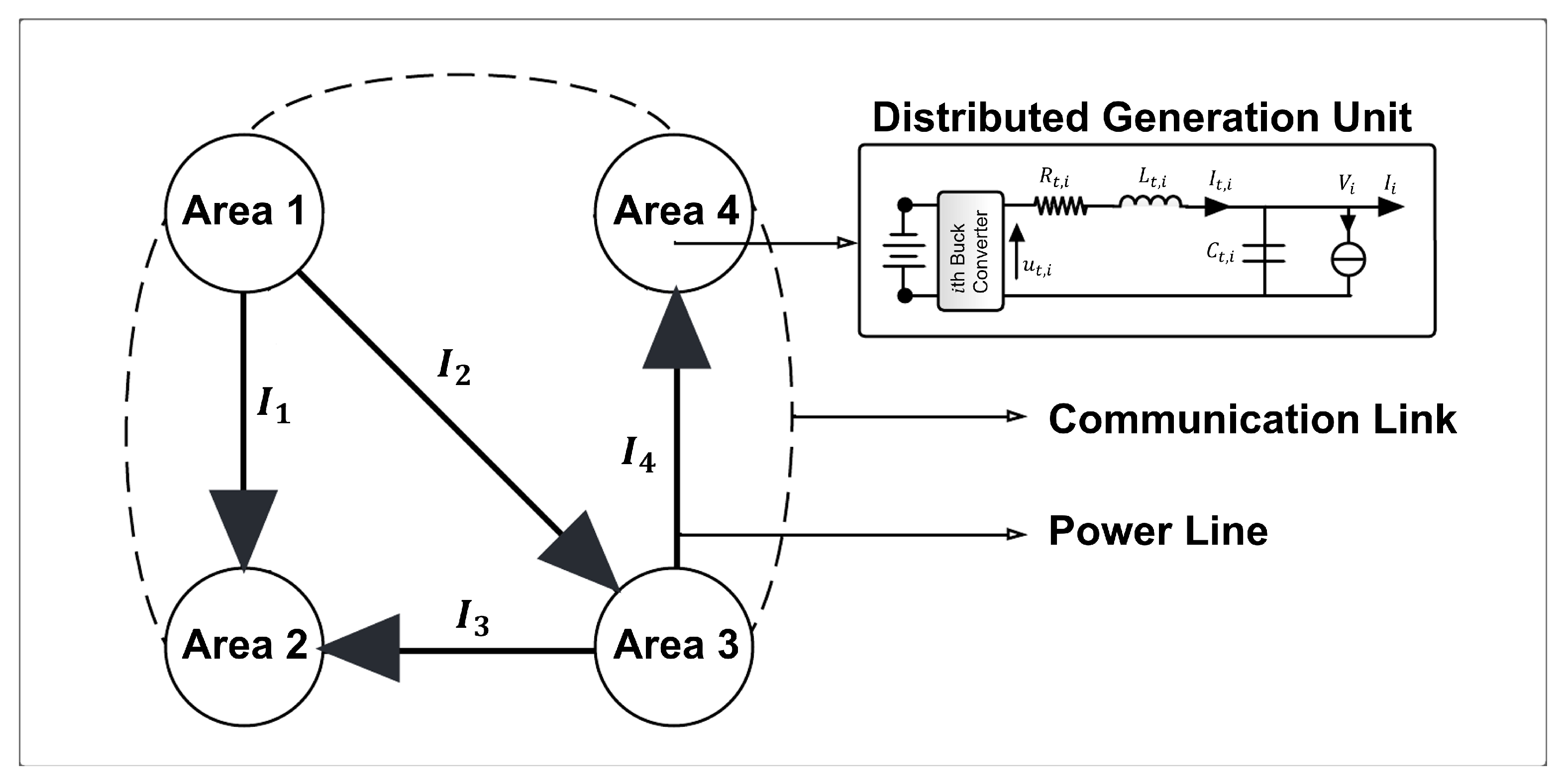
Each agent in Figure 1 represents the DGU and the DC load that together with other agents form a multi-agent network. These DGUs interconnect within a DC microgrid, as illustrated in Figure 2. DC microgrid represented in Figure 2 possesses two sorts of links, the first is the power lines that represent the direction of current flow among different agents and the second is the communication links that share state information among different agents. The communication links are undirected and represent the multi-agent network for the DC microgrid. The undirected communication graph is modeled as G D C m i c r o g r i d = ( α , β ) , where α = { α 1 , α 2 , , α n } is the set of nodes or the set of the total number of areas, as shown in Figure 2 and β α × α is the set of edges. Each node represents the DGU and DC load and interconnected power lines.
The adjacency and Laplacian matrices are given below for the communication links shown in Figure 2 for the DC microgrid:
A = 0 1 0 1 1 0 0 0 0 0 0 1 1 0 1 0 ; L = 2 1 0 1 1 1 0 0 0 0 1 1 1 0 1 2 ;
The communication links are undirected and strongly connected, and the resultant Laplacian matrix is symmetric. Furthermore, diagonal entries of the Laplacian matrix form a degree matrix as follows:
D = 2 0 0 0 0 1 0 0 0 0 1 0 0 0 0 2 ;

3. Voltage and Current Control Using High-Order MAS

MAS uses local information from its neighboring agents to solve complex engineering tasks. If we consider n number of agents interacting with each other, then the dynamics of kth-order or high-order linear MAS is given as
x ˙ 1 , i = x 2 , i x ˙ 2 , i = x 3 , i x ˙ k 1 , i = x k , i x ˙ k , i = f ( x i ) + u i ;
where f ( . ) is a function of the linear combination of state variables, i = 1 , 2 , 3 , , n are the number of agents, and x i = [ x 1 , i , x 2 , i , x 3 , i , , x k , i ] T and u i are the state variables and the control input signal, respectively. The above state-space equation can also be written in a compact form as follows
X ˙ = A X + B U ;
where A and B are constant matrices with compatible dimensions, X = [ x 1 , x 2 , x 3 , , x n ] T is the state vector, and U = [ u 1 , u 2 , u 3 , , u n ] T is the control input vector. The dynamics of the MAS could be first-order, second-order, or high-order, as well as continuous-time or discrete-time. Ref. [31] proposes distributed control for first-order and second-order MAS. In [32], high-order discrete-time MAS is considered and a distributed controller is constructed with constraint and communication delay in the dynamical model of MAS.
The dynamical model of the DGU comprises the dynamics of voltage at the PCC and the generator current. Figure 2 illustrates the DGU that consists of a buck converter to produce DC power. The distributed voltage in the PCC is represented by V i , and the generator current flowing through the inductor is given by I t , i . The dynamical model of the ith DGU is modeled as follows,
C t , i V ˙ i = I t , i I i Z I P i L t , i I ˙ t , i = V i R t , i I t , i + u t , i ;
where C t , i , L t , i and R t , i are the capacitance, inductance, and resistance of the ith DGU. V i and I t , i are the state variables that represent the voltage in the PCC and the generator current passing through the inductor, respectively. u t , i is the input control signal for ith DGU. Z I P = [ Z I P 1 , Z I P 2 , , Z I P n ] T is the standard ZIP load which is modeled as follows [33]:
Z I P = Y L V + I L + P L * V ;
Moreover, I i is the net current that flows out or flows into the ith DGU and I i > 0 if, and only if, there exists a connection between two or more DGUs. If there exists no connection between ith and jth DGUs, then the net current will be zero, that is, I i = 0 . The directed graph of the power lines in Figure 2 shows the direction of the flow of net currents among the DGUs. It can be seen that there is no direct current flow between Area 1 and Area 4. The dynamical representation of net currents among DGUs can be given as follows,
I i = K ϕ , i j N i a i j I i I j = K ϕ , i j N i a i j V i R i j V j R i j ;
where K ϕ , i is the constant gain vector, I i and R i j are the line current and line resistance, respectively, and a i j > 0 if there exists a directed connection between ith and jth DGU otherwise a i j = 0 . Equation (8) can be modified as follows:
V ˙ i = C t , i 1 I t , i C t , i 1 K ϕ , i j N i a i j V i R i j V j R i j C t , i 1 Z I P i I ˙ t , i = L t , i 1 V i L t , i 1 R t , i I t , i + L t , i 1 u t , i ;
Equation (11) can also be written as follows,
V ˙ i = C t , i 1 I t , i C t , i 1 K ϕ , i j N i L ϕ , i j I L , j C t , i 1 Z I P i I ˙ t , i = L t , i 1 V i L t , i 1 R t , i I t , i + L t , i 1 u t , i ;
where L ϕ , i j is the Laplacian matrix formed by the interconnected DGUs and I L , j is the line current. The dynamical model for the mth line is written as follows,
L m I ˙ L , m = R m I L , m + i N m ϕ m i ( V m V i ) ;
where I L , m , L m , and R m are the mth line current, line inductance, and line resistance, respectively. ϕ m i > 0 if there exists a voltage difference between between mth and ith DGUs otherwise ϕ m i = 0 . Equation (13) can be rearranged as follows,
I ˙ L , m = L m 1 R m I L , m + L m 1 i N m L ϕ , m i V i ;
where L ϕ , m i is the Laplacian matrix formed by interconnected DGUs and V i is the voltage in the PCC of the ith DGU ( P C C i ). To design the distributed controller using the higher-order MAS, we first need to construct the error signal e v , i for the ith DGU as follows,
e ˙ v , i = v r e f , i V i ω i ;
where e v , i is the error signal, v r e f , i is the reference voltage for the ith DGU, V i is the voltage at P C C i , and ω i is the consensus variable generated by the high-order MAS through the communication network and given by the following equation,
ω i = K c I t , i r j N i , j i a i j ( Ω i Ω j ) ;
where K c is a gain constant, I t , i r is the rated current, and Ω i is the ith vertex of the consensus protocol. Equation (15) together with Equation (16) can be written as follows,
e ˙ v , i = v r e f , i V i K c I t , i r j N i , j i L c , i j Ω j ;
where L c , i j is the Laplacian matrix formed by the undirected communication graph. The undirected communication graph is represented by the dotted lines in Figure 2. Furthermore, ω is derived using the second control layer that controls the current among loads within the multi-agent network. If ω = 0 , the primary control layer works to control the suitable reference voltage in the PCC. The load is distributed proportionally among distributed MAS if,
I t , i I t , i r I t , j I t , j r = 0 for all i , j V ;
and, consequently, the consensus protocol can be constructed as follows:
Ω ˙ i = j N i , j i a i j I t , i I t , i r I t , j I t , j r ;
The overall dynamical model of the distributed DC microgrid can be written as follows.
V ˙ i = C t , i 1 I t , i C t , i 1 K ϕ , i j N i L ϕ , i j I j C t , i 1 Z I P i I ˙ t , i = L t , i 1 V i L t , i 1 R t , i I t , i + L t , i 1 u t , i e ˙ v , i = v r e f , i V i K c I t , i r j = 1 , j i N L c , i j Ω j I ˙ L , m = L m 1 R m I L , m + L m 1 i N m L ϕ , m i V i Ω ˙ i = j N i , j i L c , i j ( I t , j r ) 1 I t , j ;
Additionally, the compact form of Equation (20) is written as follows,
X ˙ = A X + B U + M Y = H X ;
where X = [ V , I t , e v , I L , Ω ] T is the state vector, Y is the output vector, and
A = C t 1 Y L C t 1 0 C t 1 K ϕ L ϕ 0 L t 1 L t 1 R t 0 0 0 I 0 0 0 ( I t r ) 1 K c L c L 1 L ϕ 0 0 L 1 R 0 0 ( I t r ) 1 L c 0 0 0 ; B = 0 L t 1 0 0 0 ;
M = C t 1 I L + V 1 P L * 0 v r e f 0 0 ; H = 1 1 1 1 1 ;
Distributed control signals are designed for voltage tracking in the PCC and current sharing among distributed loads as follows,
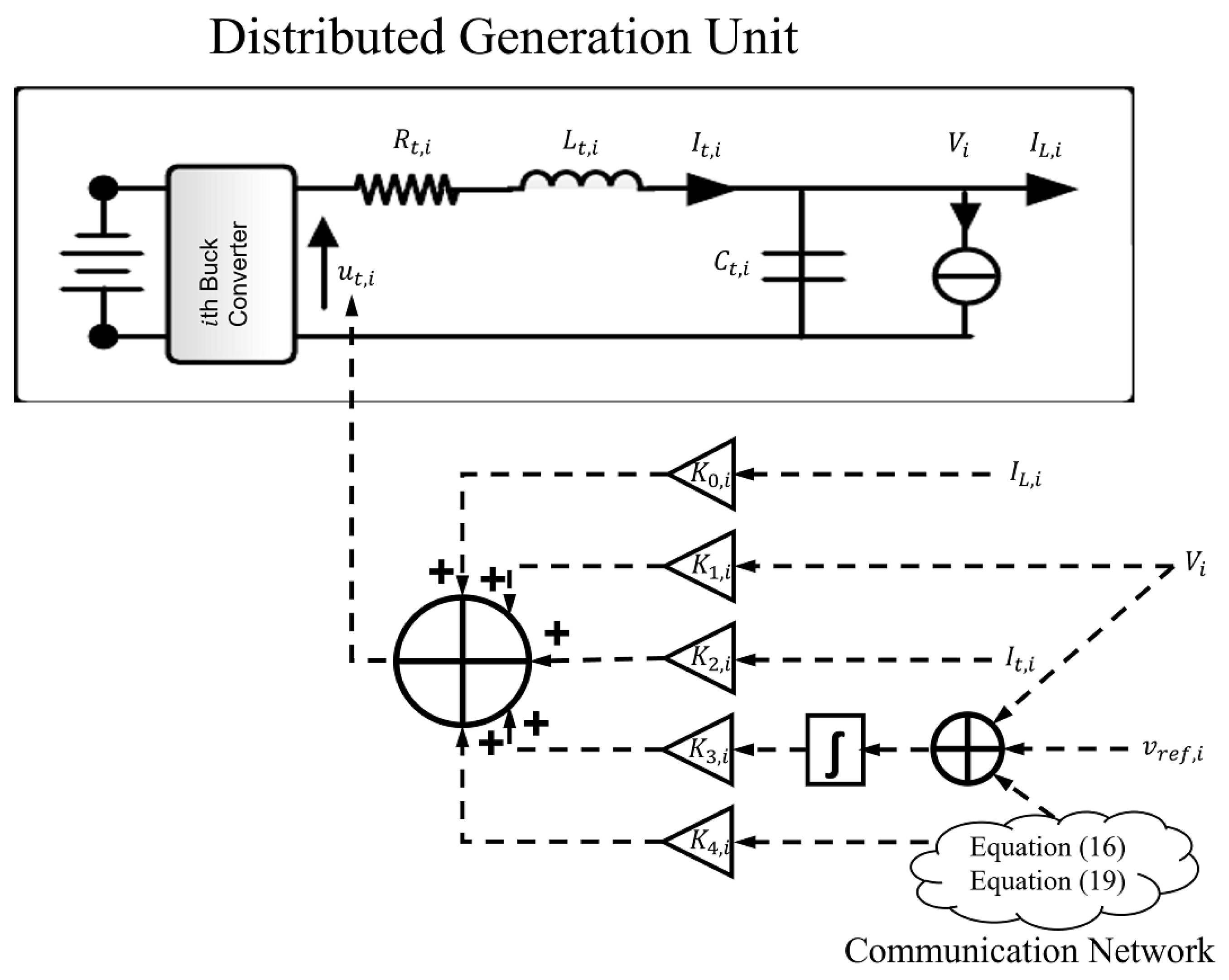
u t , i = K 0 , i I L , i + K 1 , i V i + K 2 , i I t , i + K 3 , i e v , i + K 4 , i Ω i ;
where K 0 , i , K 1 , i , K 2 , i , K 3 , i , and K 4 , i are the control gains.
Figure 3 illustrates the architecture of the proposed distributed controller for the DC microgrid. The dotted lines represent the control signals. The control gains K 0 , i , K 1 , i , K 2 , i , K 3 , i , and K 4 , i used in Figure 3 are optimized and evaluated using the Lyapunov stability criteria in the following section. Furthermore, the line current, voltage at PCC, and current passing through the filter are taken from the DGU, as shown in Figure 3, whereas the communication network of the higher-order MAS determines the consensus variable and consensus protocol, as given in Equation (16) and Equation (19), respectively.
The compact form of the distributed control signals can be written as follows,
U = K X ;
where K = [ K 0 , K 1 , K 2 , K 3 , K 4 ] . The closed-loop system can be written as follows,
X ˙ = A ˜ X + M Y = H X ;
where A ˜ = A + B K and given by the following expression:
A ˜ = C t 1 Y L C t 1 0 C t 1 K ϕ L ϕ 0 ( K 1 1 ) L t 1 ( K 2 R t ) L t 1 K 3 L t 1 K 0 L t 1 K 4 L c ( L t I t r ) 1 I 0 0 0 ( I t r ) 1 K c L c L 1 L ϕ 0 0 L 1 R 0 0 ( I t r ) 1 L c 0 0 0 ;
Steady-state solution
0 = C t 1 Y L V ¯ + C t 1 I ¯ t C t 1 K ϕ L ϕ I ¯ L C t 1 I ¯ L + V ¯ 1 P L * 0 = ( K 1 1 ) L t 1 V ¯ + ( K 2 R t ) L t 1 I ¯ t + K 3 L t 1 e ¯ v + K 0 L t 1 I ¯ L + K 4 L c ( L t I t r ) 1 Ω ¯ 0 = V ¯ ( I t r ) 1 K c L c Ω ¯ + v r e f 0 = L 1 L ϕ V ¯ L 1 R I ¯ L 0 = ( I t r ) 1 L c I ¯ t ;
Simplifying:
0 = Y L V ¯ + I ¯ t ( K ϕ L ϕ + 1 ) I ¯ L V ¯ 1 P L * 0 = ( K 1 1 ) V ¯ + ( K 2 R t ) I ¯ t + K 3 e ¯ v + K 0 I ¯ L + K 4 L c ( I t r ) 1 Ω ¯ 0 = V ¯ ( I t r ) 1 K c L c Ω ¯ + v r e f 0 = L ϕ V ¯ R I ¯ L 0 = ( I t r ) 1 L c I ¯ t ;
L ϕ is the Laplacian matrix constructed using the power connection among distributed networks formed by the DGUs and 1 n T L ϕ = 0 n which results in K ϕ L ϕ I ¯ L = 0 in the above equation. Similarly, L c is the Laplacian matrix constructed using the communication network for second-layer control and 1 m T L c = 0 m . Furthermore, in order to assure load sharing, there exists a relationship I ¯ t = μ I t r 1 n for a variable μ R . For voltage control at the steady state, there exists a Ω ¯ , such that I t r ( v r e f V ¯ ) F ( Ω ¯ ) . After simplifications and rearrangements, the following expressions are formed.
I ¯ t = Y L V ¯ + V ¯ 1 P L * + I ¯ L e ¯ v = K 3 1 [ ( 1 K 1 ) V ¯ + ( R t K 2 ) I ¯ t + K 0 I ¯ L + K 4 ( K c ) 1 ( V ¯ v r e f ) ] Ω ¯ = I t r ( v r e f V ¯ ) I ¯ L = R 1 L ϕ V ¯ I ¯ t = μ I t r ;

4. Closed-Loop Stability for DC Microgrids

The stability of the closed-loop dynamical system formed by Equation (26) is performed using the following Lyapunov candidate function Γ :
Γ ( X ˜ ) = 1 2 X ˜ T P X ˜ + 1 2 M T M ;
where X ˜ = X X ¯ and P is the positive definite and given by,
P = C t 0 0 0 0 0 P 1 P 2 0 0 0 P 3 P 4 0 0 0 0 0 L 0 0 0 0 0 I ;
where P is the block diagonal matrix with C t 0 , L 0 and I 0 , and
P ^ = P 1 P 2 P 3 P 4 0 ;
where:
P 1 = L t 1 ( K 2 R t ) K p 1 P 2 = L t 1 K 3 K p 1 P 3 = P 2 P 4 = L t 2 K 3 ( K 1 1 ) K p 1 K p = L t 1 K 3 L t 2 ( K 1 1 ) ( K 2 R t ) ;
Equation (33) is a symmetric block matrix, and if P 4 is invertible, then the following equation can be written,
P ^ i = P 1 i P 2 i P 2 i P 4 i R 2 × 2 ;
where P 1 i , P 2 i , and P 4 i are the ith diagonal elements of the matrices P 1 , P 2 and P 4 , respectively. Furthermore, P ^ is positive definite if P ^ i 0 for all i [ 1 , 2 , 3 , , n ] . The following two conditions apply to the positive definite matrix:
  • P 4 0
  • P 1 P 2 P 4 1 P 2 0
Note that P 1 P 2 P 4 1 P 2 0 is Schur’s complement of the matrix P ^ .
For P ^ i 0 , applying Sylvester’s criterion along with some basic algebra, it is concluded that P ^ i 0 if, and only if, L t , i 1 ( K 2 , i R t , i ) , L t , i 1 K 3 , i and K p , i satisfy the following conditions:
S i = K 2 , i R t , i L t , i , K 3 , i L t , i , K p , i : K 2 , i R t , i L t , i , K p , i > 0 , K 3 , i L t , i < 0 or K 2 , i R t , i L t , i , K p , i < 0 , K 3 , i L t , i > 0 .
The time derivative of the Lyapunov candidate function is given by:
Γ ˙ ( X ˜ ) = 1 2 [ X ˜ ˙ T P X ˜ + X ˜ T P X ˜ ˙ + M T M ˙ + M ˙ T M ] ;
It is noted that M T M ˙ and M ˙ T M are equivalent, such that M T M ˙ = M ˙ T M = δ δ ˙ , where δ = C t 1 I L + V 1 P L *
Γ ˙ ( X ˜ ) = 1 2 [ X ˜ ˙ T P X ˜ + X ˜ T P X ˜ ˙ ] + δ δ ˙ Γ ˙ ( X ˜ ) = 1 2 [ ( A x X + M ) T P X ˜ + X ˜ T P ( A x X + M ) ] + δ δ ˙ Γ ˙ ( X ˜ ) = 1 2 [ X T A x T P X ˜ + X ˜ T P A x X + 2 M T P X ˜ ] + δ δ ˙ Γ ˙ ( X ˜ ) = X ˜ Q ( Γ ) X ˜ + 2 M T P X ˜ + δ δ ˙ ;
where Q ( Γ ) = A x T P + P A x . The product of M T P is negative as P is a positive definite matrix and M is a negative vector. Moreover, δ is a negative value and its derivative is a positive value as follows:
δ ˙ = C t 1 I ˙ L V 2 V ˙ P L * δ ˙ = C t 1 L 1 R I L + L 1 L ϕ V V 2 V ˙ P L * δ ˙ = C t 1 L 1 R I L + V 2 V ˙ P L * δ ˙ > 0 ;
and, consequently, δ δ ˙ < 0 . The time derivative of the Lyapunov candidate function can be written as an inequality and is given below:
Γ ˙ ( X ˜ ) X ˜ Q ( Γ ) X ˜ ;
The closed-loop system will be stable if the time-derivative of the Lyapunov candidate function is negative definite, i.e., Γ ˙ ( X ˜ ) < 0 . Furthermore, it can be concluded from Equation (40) that the Lyapunov candidate function will converge if the matrix Q ( Γ ) < 0 . The following are the necessary conditions required to attain this:
A x T P = Y L q 1 0 K ϕ T L ϕ T 0 I ( K 2 R t ) 2 L t 2 K p 1 ( K 2 R t ) K 3 L t 2 K p 1 0 L c ( I t r ) 1 0 ( K 2 R t ) K 3 L t 2 K p 1 K 3 2 L t 2 K p 1 0 0 K ϕ L ϕ K 0 K 2 R t L t 2 K p 1 K 0 K 3 L t 2 K p 1 R 0 0 q 2 q 3 0 0 ;
P A x = Y L I 0 K ϕ L ϕ 0 q 1 ( K 2 R t ) 2 L t 2 K p 1 ( K 2 R t ) K 3 L t 2 K p 1 K 0 ( K 2 R t ) L t 2 K p 1 q 2 0 ( K 2 R t ) K 3 L t 2 K p 1 K 3 2 L t 2 K p 1 K 0 K 3 L t 2 K p 1 q 3 K ϕ T L ϕ T 0 0 R 0 0 L c ( I t r ) 1 0 0 0 ;
where
q 1 = ( K 1 1 ) ( K 2 R t ) L t 2 K 3 L t K p 1 q 2 = L c ( I t r ) 1 ( K 2 R t ) K 4 L t 2 K 3 L t K p 1 q 3 = L c ( I t r ) 1 k 3 K 4 K 3 ( K 1 1 ) L t 2 K p 1 ;
which results:
Q ( Γ ) = 2 Y L I + q 1 0 0 0 I + q 1 2 ( K 2 R t ) 2 L t 2 K p 1 2 ( K 2 R t ) K 3 L t 2 K p 1 K 0 ( K 2 R t ) L t 2 K p 1 q 2 + L c ( I t r ) 1 0 2 ( K 2 R t ) K 3 L t 2 K p 1 2 K 3 2 L t 2 K p 1 K 0 K 3 L t 2 K p 1 q 3 0 K 0 ( K 2 R t ) L t 2 K p 1 K 0 K 3 L t 2 K p 1 2 R 0 0 q 2 + L c ( I t r ) 1 q 3 0 0 ;
Moreover, we consider K 0 = 0 and K 4 = K 1 1 and then it can be further simplified as follows:
Q ( Γ ) = 2 Y L 0 0 0 0 0 2 ( K 2 R t ) 2 L t 2 K p 1 2 ( K 2 R t ) K 3 L t 2 K p 1 0 0 0 2 ( K 2 R t ) K 3 L t 2 K p 1 2 K 3 2 L t 2 K p 1 0 0 0 0 0 2 R 0 0 0 0 0 0 ;
Q ( Γ ) is negative semidefinite if, and only if, Y L 0 , R 0 , and Q ^ ( Γ ) 0 , where
Q ^ ( Γ ) = 2 ( K 2 R t ) 2 L t 2 K p 1 ( K 2 R t ) K 3 L t 2 K p 1 ( K 2 R t ) K 3 L t 2 K p 1 K 3 2 L t 2 K p 1 ;
Furthermore, Q ^ ( Γ ) 0 if K p < 0 and Equation (36) will be as follows:
S i = K 2 , i R t , i L t , i , K 3 , i L t , i , K p , i : K 2 , i R t , i L t , i , K p , i < 0 , K 3 , i L t , i > 0 .
Moreover,
S Γ , i = K 1 , i 1 L t , i , K 2 , i R t , i L t , i , K 3 , i L t , i , K p , i : K 1 , i 1 L t , i , K 2 , i R t , i L t , i , K p , i < 0 , 0 < K 3 , i L t , i < K 1 , i 1 L t , i × K 2 , i R t , i L t , i .
Equation (48) gives the necessary conditions to the control gains and constant variables required to design the distributed controller using the higher-order MAS. Moreover, the first derivative of the Lyapunov candidate function is negative definite for these conditions, which leads to the stability of the closed-loop system.

5. Results and Discussion

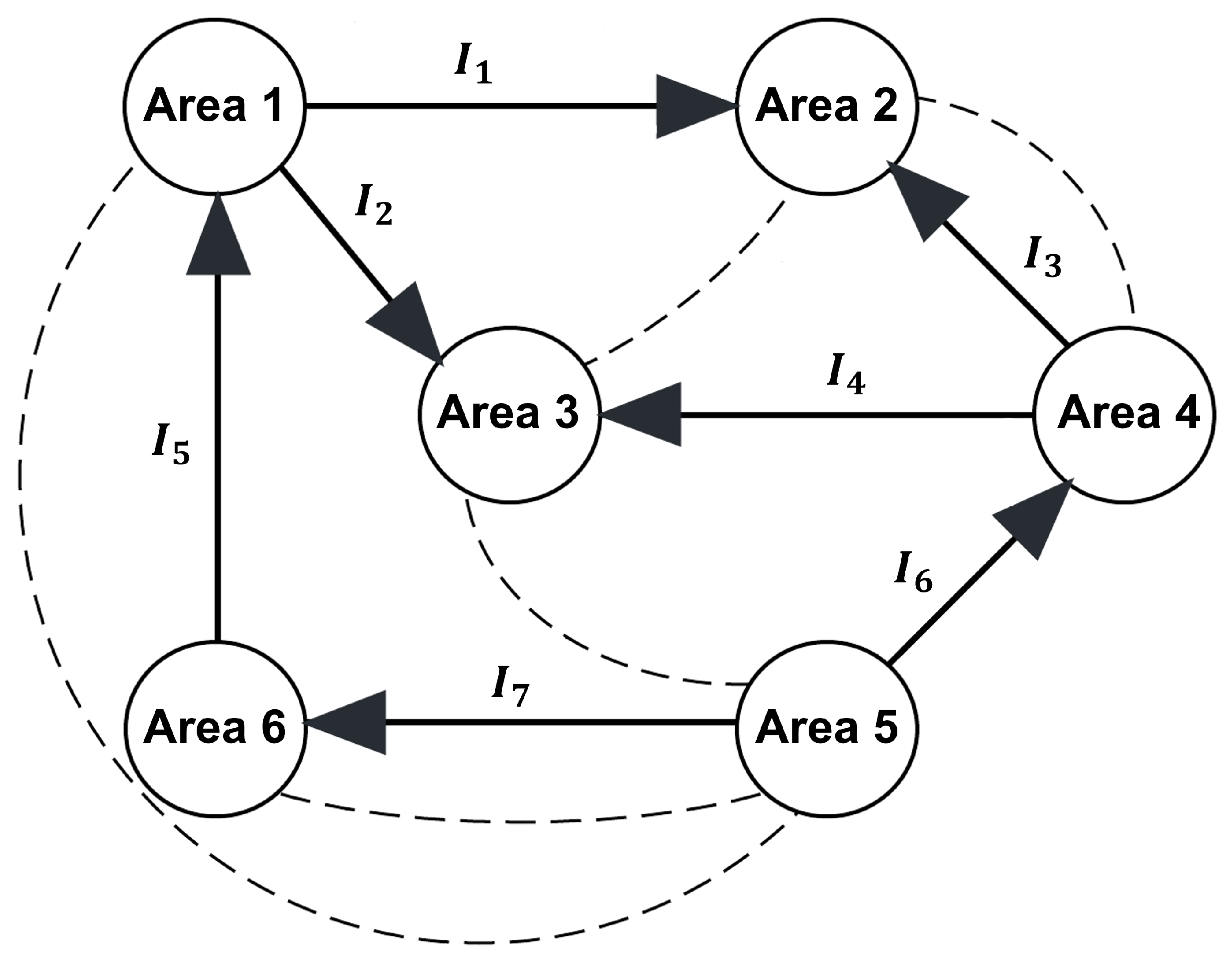
MATLAB environment was used to evaluate the performance of the distributed control algorithm for the DC microgrid using higher-order MAS. For this purpose, a distributed network consisting of six distributed areas was considered. Each distributed area was composed of its local DGU, dynamic RLC lines, and non-linear ZIP load. Furthermore, these distributed areas are also interlinked using a communication graph with each other. The graphical representation of the considered DC microgrid using MAS is represented in Figure 4 where the dotted lines represent the communication links and the arrow lines represent the flow of power. Communication links are bidirectional, whereas power lines are directional and possess switches to handle the power flow between distributed areas. The considered MAS has six agents or DGUs that form seven directed power flow lines and five undirected communication links.
At the time t < 0 , all areas are disconnected, that is, a i j = 0 ; consequently ω i = 0 in Equation (15) and the error signal is constructed using the primary voltage and the reference voltage v r e f , i for each DGU at the PCC as follows:
e ˙ v , i = v r e f , i V i ;
where i = 1 , 2 , 3 , 4 , 5 , 6 . At the time t = 0 , the communication graph is established according to Figure 4 and, therefore, ω i 0 , which enforces the secondary control of the distributed MAS to control the voltage in each PCC of the distributed areas and the current control for the distributed loads between each area.
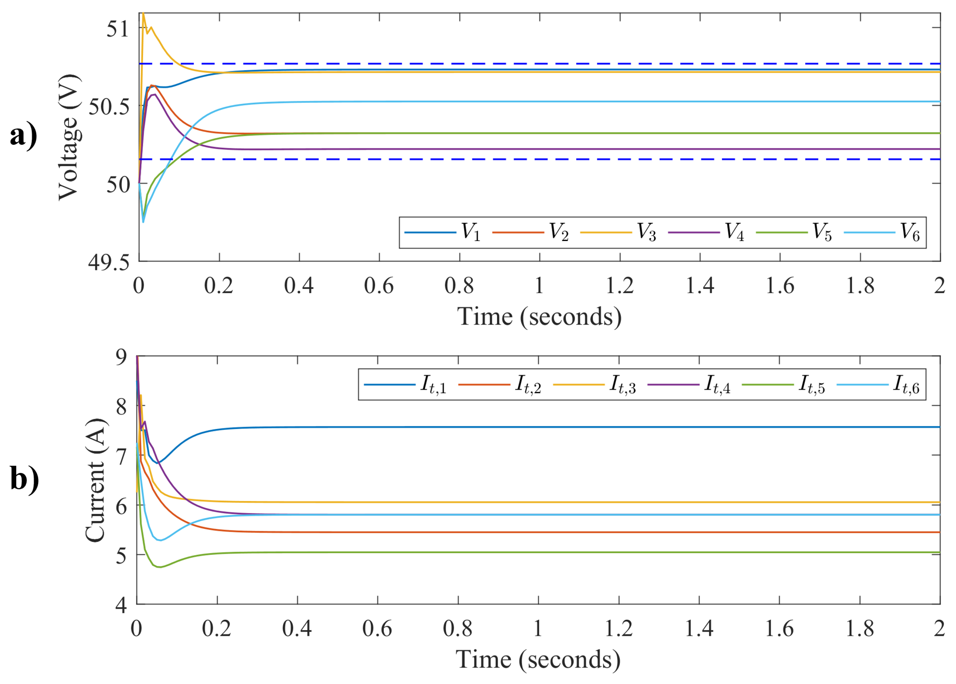
First, the simulation was run for 2 s with a unique reference voltage V r e f * = [ 50.1 , 50.5 , 51 , 51.5 , 49.4 , 50.4 ] T . To simplify the computing, the gain vector K ϕ , and K c are considered as unity in the Equation (20) and the control gains K = [ k 0 , i , k 1 , i , k 2 , i , k 3 , i , k 4 , i ] T are chosen, such that the closed-loop dynamical system is stable. It is noted from the stability analysis that k 0 , i is zero and k 4 , i = k 1 , i 1 . Table 1 includes the control gains used in the simulation:
Figure 5 illustrates the voltage and current trajectories for each DGU when the proposed distributed controller is applied to the DC microgrid. The goals of the proposed controller are to maintain the voltage in the PCC for each DGU and to distribute the power proportionally among the loads at each DGU. Furthermore, it can be seen that voltage trajectories are limited within an upper and lower bound when the proposed distributed controller is applied to the DC microgrid. The dotted lines in Figure 5a show the upper and lower bounds of the unique reference voltage V r e f * . Figure 5 shows that voltages and currents attain steady states and, therefore, equilibrium stability is achieved. It can also be seen that the distributed voltages are within the bounded area and the distributed currents are proportional to the load distribution.
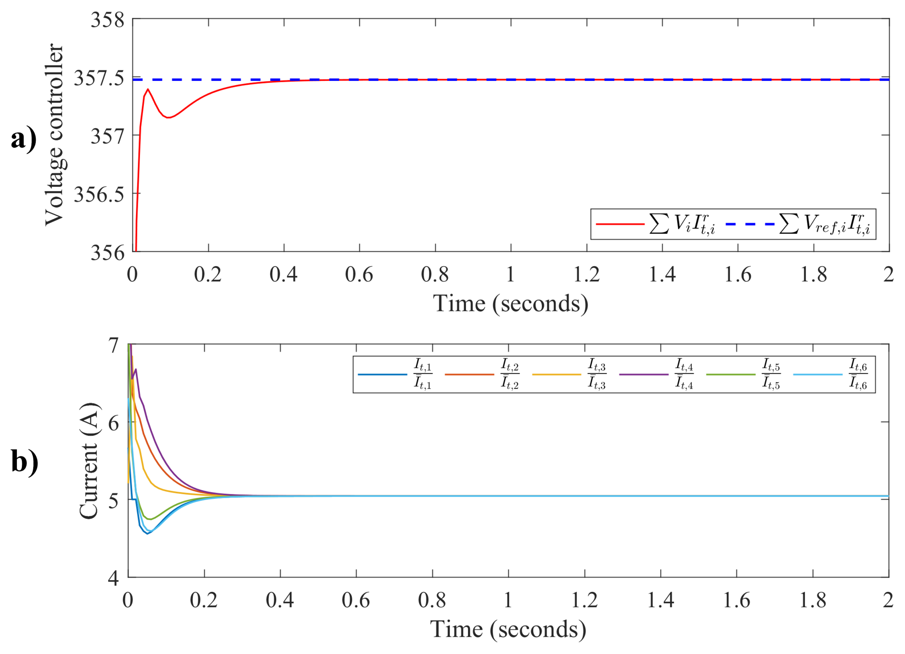
The following rated currents were used in the simulation, I t r = [ 1.5 , 1.08 , 1.2 , 1.15 , 1 , 1.15 ] T . The sum of the weighted reference voltage V r e f , i I t , i r and the sum of the weighted filtered voltage V i I t , i r were computed using the rated currents I t r . Figure 6 shows the sum of the weighted filtered voltage control and the weighted filtered current control, respectively. It can be seen in Figure 6a that the sum of the weighted filtered voltage tracks the sum of the weighted reference voltage. Furthermore, the directed graph of power flow in Figure 4 forms a complex network where the current flow among DGUs must attain the consensus when distributed control is applied to the high-order dynamical model of the DC microgrid. Figure 6b shows the results of the weighted filtered current control that achieves the distributed consensus when the proposed distributed controller is applied.
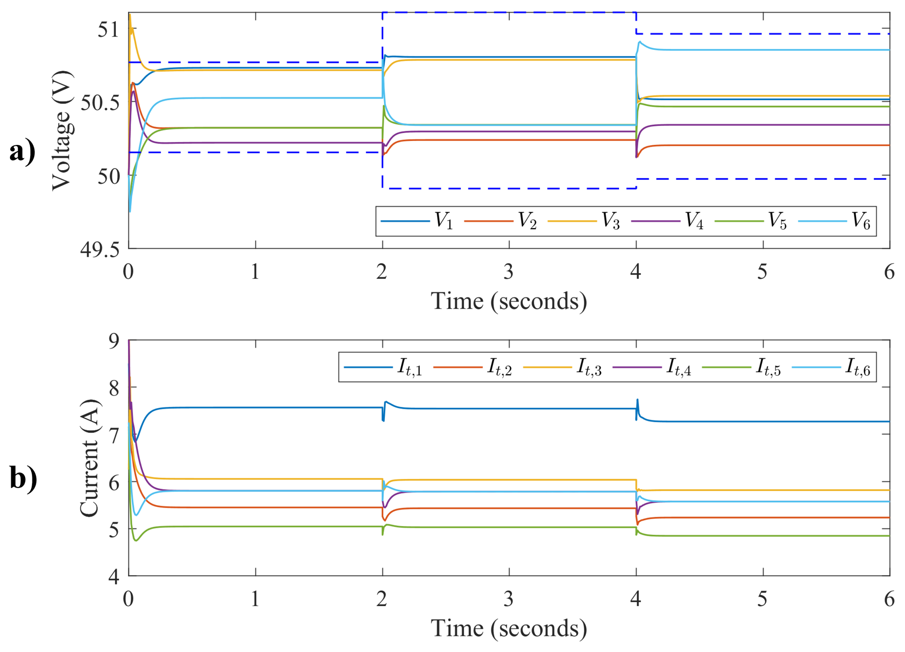
Next, the simulation was run for 6 s with a change in non-linear ZIP load to verify the performance of the proposed distributed control algorithm for the DC microgrid. The non-linear ZIP load was changed at t = 2 and t = 4 s, respectively. Figure 7 shows the distributed voltages in the PCC and the current trajectories for each DGU. From the figure, it can be seen that there is a sudden change in voltage and current trajectories occur because of the sudden change in non-linear ZIP load at time t = 2 and t = 4 and that both voltage and current trajectories attain steady-states. From Figure 7a, it can be seen that the voltage trajectories are within bounded limits denoted by dotted lines. This ensures that the voltage in each PCC is within a certain limit and tracks the desired reference voltage at each PCC when a distributed controller is applied. Furthermore, it can also be seen in Figure 7b that the current at each DGU changes with a change in ZIP load and attains a steady state.
The sum of weighted reference voltage V r e f , i I t , i r and the sum of the weighted filtered voltage V i I t , i r were computed using the same rated currents I t r given above. Figure 8 shows the weighted filtered control for the distributed DC microgrid using the higher-order dynamical system with the change in non-linear ZIP loads. Similarly to the above, a deviation in the voltage and current states occurs at t = 2 and t = 4 s, respectively, and then steady states are again achieved.
Figure 8a illustrates the weighted filtered voltage control. It can be seen that the sum of the weighted filtered voltage efficiently tracks the desired trajectory of the sum of the weighted reference voltage. Furthermore, the trajectories of the weighted filtered current also achieve consensus and can be visualized in Figure 8b.
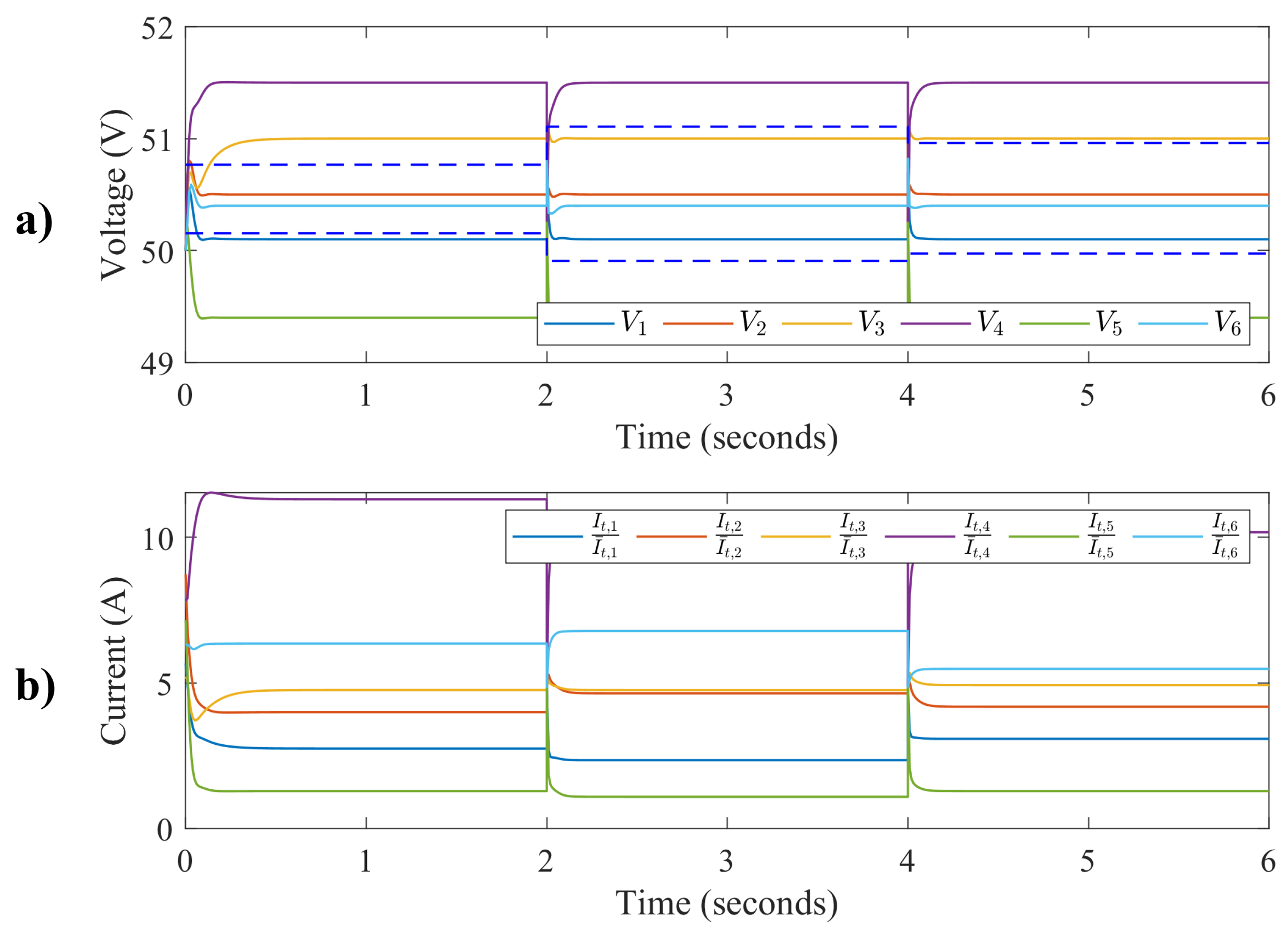
In the absence of communication links, the consensus variable and protocol will be zero, as demonstrated in Equation (16) and Equation (19), respectively, and illustrated in Figure 3. Results are presented below when communication links are absent. First, simulation results are shown in Figure 9 with constant ZIP load and without communication links. Figure 9a illustrates that the voltages at PCC are not within limits due to the lack of feedback signals from communication links. Additionally, Figure 9b demonstrates that the weighted current distribution among loads is uneven.
In addition, Figure 10a shows the voltage distribution when the ZIP load is changing, and communication links are absent. The results indicate that the voltage at the PCC does not fall within the limits. Similarly, Figure 10b depicts the weighted current for the same scenario, indicating that the current is not evenly distributed among loads.
The results presented in the previous statements illustrate that the consensus variable and consensus protocol are crucial components in designing the proposed distributed controller. In the absence of communication links, both the consensus variable and protocol become zero, and the simulation results show that the voltage and current distribution among loads are not within acceptable limits.
These findings highlight the importance of utilizing the consensus variable and protocol to achieve a coordinated control strategy that ensures optimal performance and stability of the power system. The consensus variable and protocol facilitate the exchange of information and enable the distributed controller to make informed decisions regarding voltage and current regulation. Therefore, incorporating the consensus variable and protocol into the design of the distributed controller can help to overcome the limitations associated with the absence of communication links and ensure that the power system operates effectively even in challenging circumstances.
By simulating the DC microgrid with the proposed distributed controller, one can evaluate the sustainability contribution of the controller’s performance. The simulation results show that the controller can efficiently track the desired reference voltage at the PCC while distributing the control among the distributed loads, it indicates that the microgrid is operating efficiently, reducing energy losses, and promoting energy efficiency. Furthermore, the voltage and current are within a limit, it demonstrates that the microgrid is operating safely and sustainably, reducing the risk of damage to the microgrid components and improving the microgrid’s resilience to disruptions.
One limitation of the proposed controller is that the results were concluded using simulations only. This means that the controller may require parameter tuning or adjustments in other parameters, such as filters to achieve optimal performance in a real-world setting. Additionally, the simulation may not capture all the complexities and dynamics of the physical system, leading to a gap between the simulation results and the actual performance of the controller. It is important to note that the limitations of the proposed controller do not diminish the significance of the research. Instead, they highlight the need for further research and development to improve the performance and applicability of the proposed solution in practical applications.

6. Conclusions

This paper presents a distributed control algorithm for DC microgrids using higher-order MAS. Distributed controllers play a critical role in ensuring the sustainability of DC microgrids by enabling efficient and resilient energy management, facilitating the integration of renewable energy sources, and promoting equitable access to energy services. Distributed controller using MAS is an approach that uses graph theory to construct a control algorithm for complex systems, such as a DC microgrid. In a distributed control approach, each agent interacts with other agents within the complex MAS and shares information. Based on the local information, a distributed controller is constructed. The MAS control approach provides flexibility in managing DC microgrids. The agents adjust their states according to the change in power generation or load. Furthermore, distributed control for MAS is easy to implement and improves the efficiency of DC microgrids. Distributed control is a control technique that is often used in DC microgrids to stabilize the voltage at PCC and manage the power flow between distributed agents of the system. In a DC microgrid, distributed control can be used to balance the load across DGUs and to ensure that the system operates within safe limits. Rather than relying on a centralized control system that requires expensive hardware and software, distributed control can be implemented using simple control algorithms that are distributed across the system. This can make DC microgrids more affordable and accessible to a wider range of users. The dynamical model for higher-order MAS is constructed with the help of DGU, dynamical RLC lines, and non-linear ZIP load. To design the distributed control, a communication network among the MAS is used to gather information from neighboring agents. Furthermore, the stability of the closed-loop system is performed, and necessary conditions are derived to verify the performance of the proposed distributed control algorithm. Moreover, from the MATLAB/Simulink experiments, it is concluded that the proposed control algorithm under the derived control gains performed well and achieved the voltage balancing at PCC and current sharing among distributed loads.

Author Contributions

Conceptualization, M.A. (Muhammad Ahsan) and M.A. (Mohamed Abdelrahem); Methodology, M.A. (Muhammad Ahsan); Validation, M.A. (Muhammad Ahsan); Investigation, M.A. (Muhammad Ahsan) and J.R.; Writing—original draft, M.A. (Muhammad Ahsan) and M.A. (Mohamed Abdelrahem); Writing—review & editing, J.R. and M.A. (Mohamed Abdelrahem); Supervision, M.A. (Mohamed Abdelrahem); Project administration, J.R. All authors have read and agreed to the published version of the manuscript.

Funding

This research was funded by the ANID through projects FB0008, 1210208 and 1221293.

Institutional Review Board Statement

Not applicable.

Informed Consent Statement

Not applicable.

Data Availability Statement

No new data were created or analyzed in this study. Data sharing is not applicable to this article.

Acknowledgments

J. Rodriguez acknowledges the support of ANID through projects FB0008, 1210208 and 1221293.

Conflicts of Interest

The authors declare no conflict of interest.

References

  1. Qazi, A.; Hussain, F.; Rahim, N.A.; Hardaker, G.; Alghazzawi, D.; Shaban, K.; Haruna, K. Towards Sustainable Energy: A Systematic Review of Renewable Energy Sources, Technologies, and Public Opinions. IEEE Access 2019, 7, 63837–63851. [Google Scholar] [CrossRef]
  2. Marks-Bielska, R.; Bielski, S.; Pik, K.; Kurowska, K. The Importance of Renewable Energy Sources in Poland’s Energy Mix. Energies 2020, 13, 4624. [Google Scholar] [CrossRef]
  3. Yahyaoui, I.; de la Peña, N. Energy Management Strategy for an Autonomous Hybrid Power Plant Destined to Supply Controllable Loads. Sensors 2022, 22, 357. [Google Scholar] [CrossRef] [PubMed]
  4. Rojas, D.; Muñoz, J.; Rivera, M.; Rohten, J. Review of Control Techniques in Microinverters. Sensors 2021, 21, 6486. [Google Scholar] [CrossRef] [PubMed]
  5. Rana, M.; Li, L. An Overview of Distributed Microgrid State Estimation and Control for Smart Grids. Sensors 2015, 15, 4302. [Google Scholar] [CrossRef]
  6. Nasr Esfahani, F.; Darwish, A.; Williams, B.W. Power Converter Topologies for Grid-Tied Solar Photovoltaic (PV) Powered Electric Vehicles (EVs) & mdash; A Comprehensive Review. Energies 2022, 15, 4648. [Google Scholar] [CrossRef]
  7. Alotaibi, S.; Darwish, A. Modular Multilevel Converters for Large-Scale Grid-Connected Photovoltaic Systems: A Review. Energies 2021, 14, 6213. [Google Scholar] [CrossRef]
  8. Omar, N.; Kumar Tiwari, A.; Seethalekshmi, K.; Anand Shrivastava, N. A Novel Controller Design for Small-Scale Islanded Microgrid Integrated with Electric Vehicle-Based Energy Storage Management. Int. Trans. Electr. Energy Syst. 2022, 2022, 1–19. [Google Scholar] [CrossRef]
  9. Mahmoud, M.; Azher Hussain, S.; Abido, M. Modeling and control of microgrid: An overview. J. Frankl. Inst. 2014, 351, 2822–2859. [Google Scholar] [CrossRef]
  10. Nicola, M.; Nicola, C.I. Comparative Performance Analysis of the DC-AC Converter Control System Based on Linear Robust or Nonlinear PCH Controllers and Reinforcement Learning Agent. Sensors 2022, 22, 9535. [Google Scholar] [CrossRef]
  11. Chen, M.; Suliang, M.; Haiyong, W.; Jianwen, W.; Yuan, J. Distributed Control Strategy for DC Microgrids of Photovoltaic Energy Storage Systems in Off-Grid Operation. Energies 2018, 11, 2637. [Google Scholar] [CrossRef]
  12. Reddy, G.; Kumar, Y.; Chakravarthi, M. Communication Technologies for Interoperable Smart Microgrids in Urban Energy Community: A Broad Review of the State of the Art, Challenges, and Research Perspectives. Sensors 2022, 22, 5881. [Google Scholar] [CrossRef]
  13. Dragičević, T.; Lu, X.; Vasquez, J.C.; Guerrero, J.M. DC Microgrids—Part I: A Review of Control Strategies and Stabilization Techniques. IEEE Trans. Power Electron. 2016, 31, 4876–4891. [Google Scholar] [CrossRef]
  14. Meng, L.; Shafiee, Q.; Trecate, G.F.; Karimi, H.; Fulwani, D.; Lu, X.; Guerrero, J.M. Review on Control of DC Microgrids and Multiple Microgrid Clusters. IEEE J. Emerg. Sel. Top. Power Electron. 2017, 5, 928–948. [Google Scholar] [CrossRef]
  15. Tayab, U.B.; Roslan, M.A.B.; Hwai, L.J.; Kashif, M. A review of droop control techniques for microgrid. Renew. Sustain. Energy Rev. 2017, 76, 717–727. [Google Scholar] [CrossRef]
  16. Szcześniak, P.; Grobelna, I.; Novak, M.; Nyman, U. Overview of Control Algorithm Verification Methods in Power Electronics Systems. Energies 2021, 14, 4360. [Google Scholar] [CrossRef]
  17. Naik, B.; Mehta, A. Sliding mode controller with modified sliding function for DC-DC Buck Converter. ISA Trans. 2017, 70, 279–287. [Google Scholar] [CrossRef]
  18. Jasim, A.; Jasim, B.; Bureš, V.; Mikulecký, P. A New Decentralized Robust Secondary Control for Smart Islanded Microgrids. Sensors 2022, 22, 8709. [Google Scholar] [CrossRef]
  19. Kantamneni, A.; Brown, L.E.; Parker, G.; Weaver, W.W. Survey of multi-agent systems for microgrid control. Eng. Appl. Artif. Intell. 2015, 45, 192–203. [Google Scholar] [CrossRef]
  20. Ahsan, M.; Ma, Q. Bipartite Containment Control of Multi-Agent Systems. In Proceedings of the 2019 IEEE/ASME International Conference on Advanced Intelligent Mechatronics (AIM), Hong Kong, China, 8–12 July 2019; pp. 895–900. [Google Scholar] [CrossRef]
  21. Hornik, T.; Zhong, Q.C. A Current-Control Strategy for Voltage-Source Inverters in Microgrids Based on H and Repetitive Control. IEEE Trans. Power Electron. 2011, 26, 943–952. [Google Scholar] [CrossRef]
  22. Nguyen, T.L.; Guillo-Sansano, E.; Syed, M.; Nguyen, V.H.; Blair, S.; Reguera, L.; Tran, Q.T.; Caire, R.; Burt, G.; Gavriluta, C.; et al. Multi-Agent System with Plug and Play Feature for Distributed Secondary Control in Microgrid—Controller and Power Hardware-in-the-Loop Implementation. Energies 2018, 11, 3253. [Google Scholar] [CrossRef]
  23. Sahoo, S.K.; Sinha, A.K.; Kishore, N.K. Control Techniques in AC, DC, and Hybrid AC–DC Microgrid: A Review. IEEE J. Emerg. Sel. Top. Power Electron. 2018, 6, 738–759. [Google Scholar] [CrossRef]
  24. Nasirian, V.; Moayedi, S.; Davoudi, A.; Lewis, F.L. Distributed Cooperative Control of DC Microgrids. IEEE Trans. Power Electron. 2015, 30, 2288–2303. [Google Scholar] [CrossRef]
  25. Nahata, P.; Soloperto, R.; Tucci, M.; Martinelli, A.; Ferrari-Trecate, G. A passivity-based approach to voltage stabilization in DC microgrids with ZIP loads. Automatica 2020, 113, 108770. [Google Scholar] [CrossRef]
  26. Tucci, M.; Riverso, S.; Ferrari-Trecate, G. Line-Independent Plug-and-Play Controllers for Voltage Stabilization in DC Microgrids. IEEE Trans. Control. Syst. Technol. 2018, 26, 1115–1123. [Google Scholar] [CrossRef]
  27. Tucci, M.; Meng, L.; Guerrero, J.M.; Ferrari-Trecate, G. Stable current sharing and voltage balancing in DC microgrids: A consensus-based secondary control layer. Automatica 2018, 95, 1–13. [Google Scholar] [CrossRef]
  28. Zhao, J.; Dörfler, F. Distributed control and optimization in DC microgrids. Automatica 2015, 61, 18–26. [Google Scholar] [CrossRef]
  29. Trip, S.; Cucuzzella, M.; Cheng, X.; Scherpen, J. Distributed Averaging Control for Voltage Regulation and Current Sharing in DC Microgrids. IEEE Control Syst. Lett. 2019, 3, 174–179. [Google Scholar] [CrossRef]
  30. Lee, J.; Back, J. Robust Distributed Cooperative Controller for DC Microgrids with Heterogeneous Sources. Int. J. Control. Autom. Syst. 2021, 19, 736–744. [Google Scholar] [CrossRef]
  31. Mo, L.; Pan, T.; Guo, S.; Niu, Y. Distributed Coordination Control of First- and Second-Order Multiagent Systems with External Disturbances. Math. Probl. Eng. 2022, 2015, 7. [Google Scholar] [CrossRef]
  32. Tan, C.; Cui, Y.; Li, Y. Global Consensus of High-Order Discrete-Time Multi-Agent Systems with Communication Delay and Saturation Constraint. Sensors 2022, 22, 1007. [Google Scholar] [CrossRef] [PubMed]
  33. Zonetti, D.; Saoud, A.; Girard, A.; Fribourg, L. Decentralized monotonicity-based voltage control of DC microgrids with ZIP loads⁎⁎This work has been supported by Labex DigiCosme (project ANR-ll-LABEX-0045-DIGICOSME) operated by ANR as part of the program “Investissement dAvenir” Idex Paris Saclay (ANR-11-IDEX-0003-02). IFAC-PapersOnLine. In Proceedings of the 8th IFAC Workshop on Distributed Estimation and Control in Networked Systems NECSYS 2019, Chicago, IL, USA, 16–17 September 2019; Volume 52, pp. 139–144. [Google Scholar] [CrossRef]
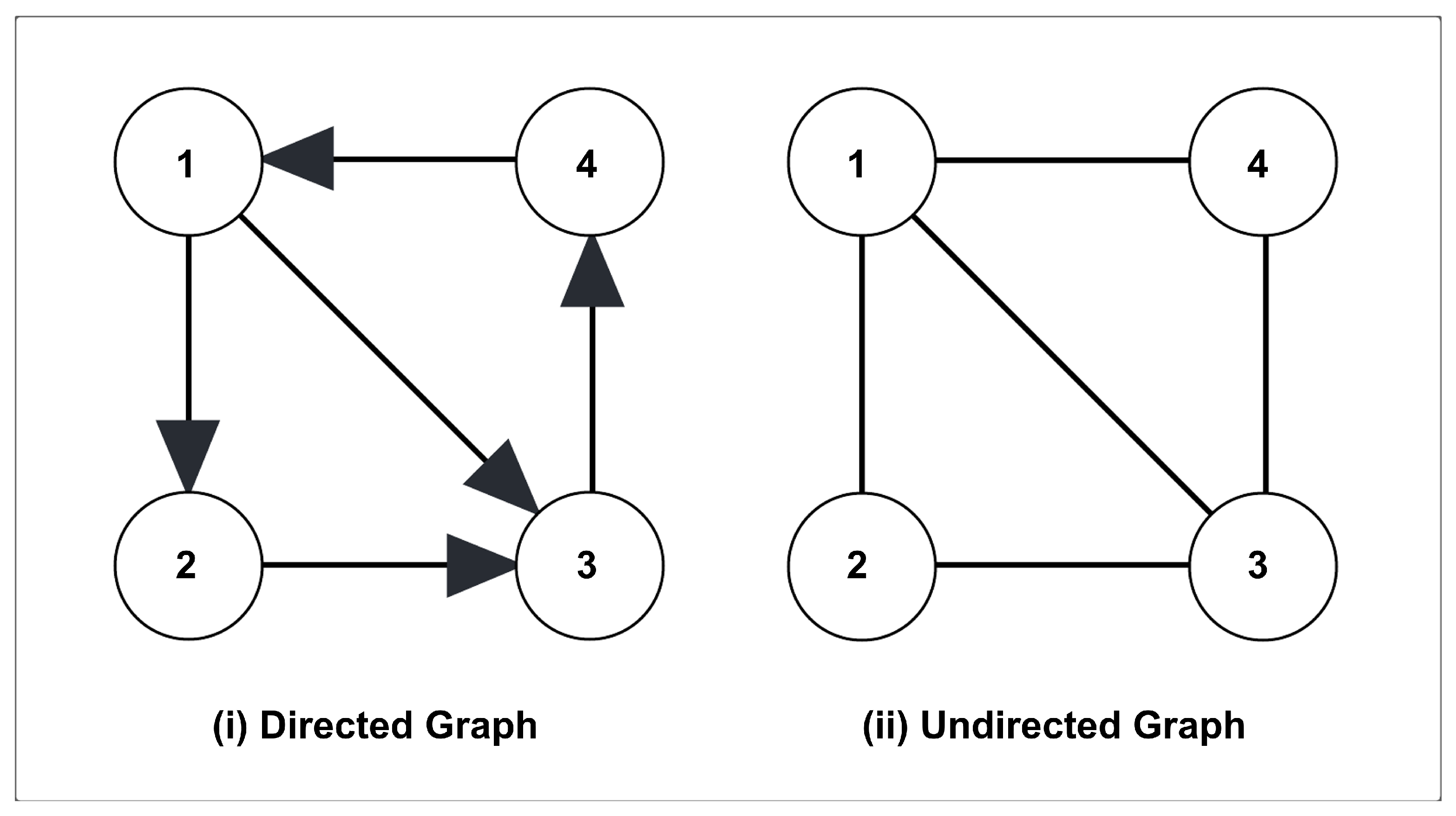
Figure 1. Communication graphs for MAS: (i) directed graph and (ii) undirected graph.
Sustainability 15 08336 g001
Figure 2. DC microgrid: MAS and communication topology for DGUs; directed lines are for power flow and dotted lines are for communication flow.
Sustainability 15 08336 g002
Figure 3. Architecture of the proposed distributed control algorithm for the DC microgrid.
Sustainability 15 08336 g003
Figure 4. Communication graphs for the distributed microgrid.
Sustainability 15 08336 g004
Figure 5. Distributed control: (a) voltage control at the PCC and (b) current control at the power line.
Sustainability 15 08336 g005
Figure 6. Weighted filtered control for the distributed DC microgrid using higher-order MAS: (a) weighted filtered voltage control and (b) weighted filtered current control.
Sustainability 15 08336 g006
Figure 7. Distributed control with a change in non-linear ZIP load: (a) voltage control at the PCC and (b) current control at the power line.
Sustainability 15 08336 g007
Figure 8. Weighted filtered control for distributed DC microgrid using higher-order MAS with change in non-linear ZIP loads: (a) weighted filtered voltage control and (b) weighted filtered current control.
Sustainability 15 08336 g008
Figure 9. Distributed control for the DC microgrid in the absence of communication links: (a) voltage control at the PCC and (b) weighted filtered current control.
Sustainability 15 08336 g009
Figure 10. Distributed control for the DC microgrid in the absence of communication links and change in ZIP load: (a) voltage control at the PCC and (b) weighted filtered current control.
Sustainability 15 08336 g010
Table 1. Control gains.
Control Gains K for the Proposed Controller
Agent i k 1 k 2 k 3 k 4
i = 1 −10.1055.56−2
i = 2 −10.1575−2
i = 3 −10.0522.73−2
i = 4 −10.2583.3−2
i = 5 −10.20166.7−2
i = 6 −10.30120−2
Disclaimer/Publisher’s Note: The statements, opinions and data contained in all publications are solely those of the individual author(s) and contributor(s) and not of MDPI and/or the editor(s). MDPI and/or the editor(s) disclaim responsibility for any injury to people or property resulting from any ideas, methods, instructions or products referred to in the content.