Article

Numerical Optimization of Mini Centrifuge Modelling Test Design of Excavation Unloading Influence on Existing Tunnel Controlled by Partition Piles

1
School of Civil Engineering, Tianjin University, Tianjin 300072, China
2
Key Laboratory of Coast Civil Structure Safety of the Ministry of Education, Tianjin University, Tianjin 300072, China
*
Author to whom correspondence should be addressed.
Sustainability 2023, 15(10), 8353; https://doi.org/10.3390/su15108353
Submission received: 22 March 2023 / Revised: 14 May 2023 / Accepted: 18 May 2023 / Published: 21 May 2023
(This article belongs to the Section Sustainable Transportation)

Abstract

:
Partition piles are widely used in tunnel displacement control under excavation. However, the control effect of partition piles has not been systematically studied, and the centrifuge model test is lacking. In view of this situation, the centrifuge model test design of the deformation of the adjacent existing tunnel caused by the excavation in terms of the partition piles under the dry sand foundation was carried out, and a series of optimization designs were carried out in the experimental design process according to the numerical simulation results. In addition, the numerical simulation of the centrifuge model test was carried out, and the calculated results were discussed and analyzed. The conclusions were obtained as follows: The magnesium-aluminum alloy materials were used to model the structural members, and its elastic modulus was close to that of common reinforced concrete; the high precision digital image correlation technology (DIC) was used to measure the horizontal and vertical displacement of the tunnel. The results of numerical simulation show that the embedded partition piles can play a better role in controlling the tunnel displacement than the non-partition piles and the non-embedded partition piles.

1. Introduction

As an effective way to alleviate the pressure of urban traffic, urban underground rail transit has sprung up nationwide and even worldwide. The construction of rail transit is an important way for urban sustainable development. First of all, it can greatly reduce the urban land use area, thus alleviating the congestion of ground traffic. Secondly, the efficient operation of infrastructure provided by rail transit reflects the economic sustainability of the city. Finally, rail transit has relatively little damage to the environment in various transportation methods, which can save a lot of one-time resources. That reflects its environmental sustainability.
In the coastal soft soil areas, with the rapid development of urban rail transit, the surrounding deep and large foundation pit projects continue to emerge. At present, the foundation pit engineering in soft soil areas is developing in the direction of deep excavation. At the same time, with the construction of a large number of underground infrastructure such as urban subways and urban underground pipe corridors, more and more excavations are adjacent to existing subway tunnels. The influence of excavations on adjacent existing tunnels has become a prominent problem worthy of attention in urban underground engineering construction. At the same time, the protection of the existing tunnel to ensure its long-term sustainable operation is also an embodiment of sustainable development.
There is often a certain distance between the existing tunnel and the retaining structure. In engineering practice, partition piles (walls) are often set at this position to block the transmission of the influence of excavation deformation on the soil, so as to reduce the deformation of the existing tunnel [1,2,3].
However, relevant research shows that the influence of the existence of the partition piles on the displacement field of the deep soil outside the excavation varies greatly with the depth [1,2]. Based on the field-measured data, Zheng et al. [1] used the numerical analysis method to study the influence of partition piles on the soil displacement field in the active area outside the excavation. As shown in Figure 1a, The numerical analysis results show that after the completion of the excavation, the soil in the red area will slide into the excavation significantly because of the excavation unloading effect. Figure 1b shows that the partition piles significantly affect the soil displacement in the active area, and have the opposite effect in different areas. This showed that a further study of the deformation control effect of partition piles on deep tunnels is needed.
In recent years, many studies focused on the protective effect of partition piles have been conducted [3,4,5,6,7,8,9,10,11,12,13,14,15,16]. In recent years, numerical simulation is a very common, simple and effective research method in geotechnical engineering. Marta [4] studied the influence of the deep excavation of an office building in Prague on underground tunnels. Two-dimensional finite element model simulated the whole process of tunnel construction, and calculated the deformation and stress changes caused by excavation. The comparison shows that the calculation results of the tunnel deformation by the numerical simulation are in good agreement with the actual measurement results. Based on a deep and large excavation protected by the partition piles, Zheng et al. [6] have studied the protection mechanism of partition piles by the finite element method. The results showed that when the traction effect was large, the partition pile would increase the horizontal displacement of the soil and the tunnel within a certain depth.
The centrifuge model test is a real and reliable research method in geotechnical engineering, so it is necessary to use the centrifuge model test to study the protective effect of partition piles. Some scholars have carried out some tests [17,18,19,20]. Ng et al. [17] designed and carried out two three-dimensional centrifuge tests in dry sand. It was found that the influence range of excavation on the vertical displacement of the tunnel was about 1.2 times the length of the excavation. Xu et al. [18] carried out a series of centrifuge model tests. It was found that the influence range of the tunnel heave was about 2.5 times the width of the excavation from the excavation boundary. Chen et al. [20] carried out the three-dimensional centrifuge model test and numerical analysis of the influence of excavation on the side tunnel in dry sand and analyzed the protective effect of partition wall. The test results show that the partition wall can reduce the surface settlement, the change of soil pressure outside the tunnel, the horizontal displacement of the retaining wall and the bending moment of the tunnel.
The above studies show that partition piles can play a positive role in tunnel deformation protection, but systematic research about the protection effect of partition piles can not be founded. The finite element method was used in most of the research, and the centrifuge model test was relatively limited. This is mainly because compared with the conventional model test, the actual operation of the centrifuge model test is more difficult. It is necessary to further carry out centrifuge model tests on the deformation of adjacent tunnels protected by isolated piles and optimize the test design from the technical aspect.
This paper mainly focused on the centrifuge model test design and optimization of the deformation of the adjacent existing tunnel caused by the excavation in terms of the partition pile under the dry sand. At the same time, the numerical simulation of the centrifuge model test was conducted. The numerical simulation results show that the actual tunnel displacement of the model is too small, and the measured value in the model test should reach the accuracy of 0.01 mm, which leads to the difficulty of actual measurement. Therefore, a series of optimization designs were carried out in the technical aspects, which made the experiments more real and effective and provided a reference for the subsequent centrifuge model tests.

2. Numerical Simulation

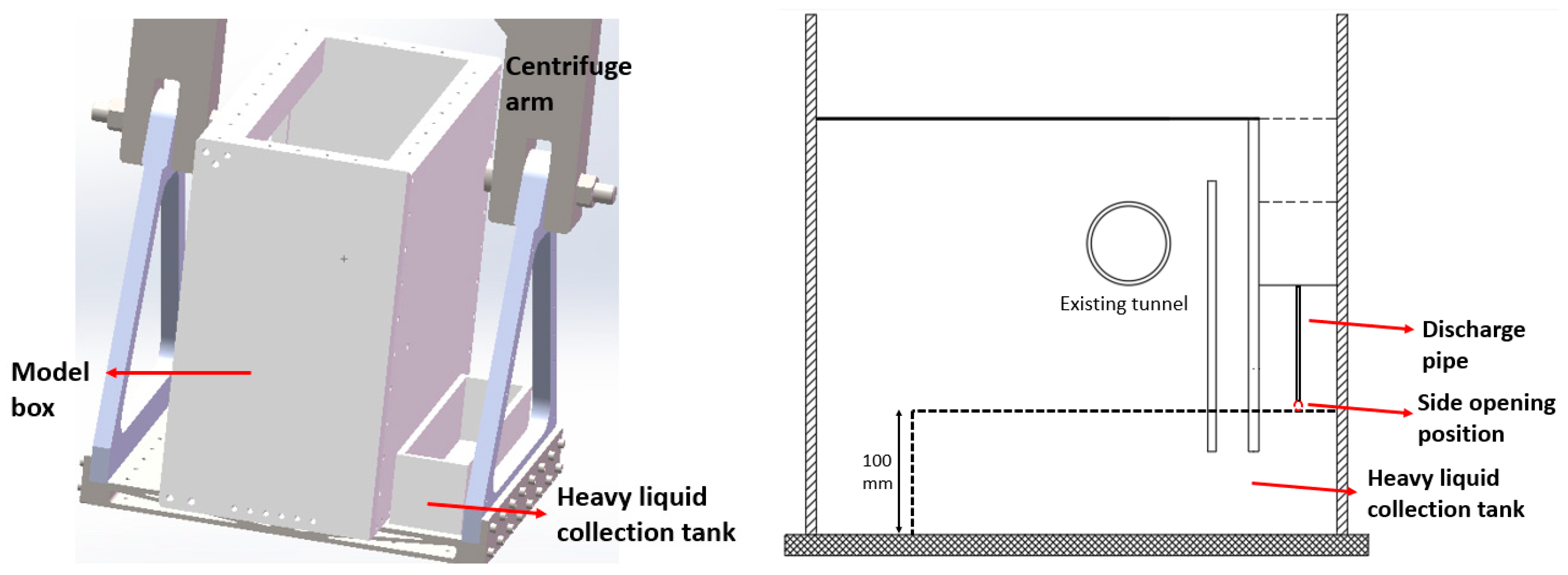
2.1. Description of the Test

The mini geotechnical centrifuge in the underground engineering laboratory of Tianjin University was used in this test. The size of the model box is 500 mm × 200 mm × 500 mm. The centrifuge is shown in Figure 2. This centrifuge model test aim to explore the influence of the parameters of partition piles on the response of the tunnel under the condition of two-dimensional excavation. In the test, the centrifuge acceleration was set to 50 g (g = 9.8 m/s2). Due to the limitation of the size of the model box, the prototype diameter of the tunnel is 4 m. The excavation depth is H = 2 D = 8 m, and the excavation width is 1.0 D = 4 m. The buried depth of the tunnel vault is S = 1.0 D = 4 m, and the distance between the tunnel and the retaining wall is 1 D = 4 m. The distance between the partition piles and the retaining wall is 0.5 D = 2 m. In the test, the design parameters of the isolated pile include the buried depth at the top of the pile h and the length of the partition pile L with h = 0 m and 8 m and L = 8 m and 16 m. The details are shown in Table 1.

2.2. Numerical Model
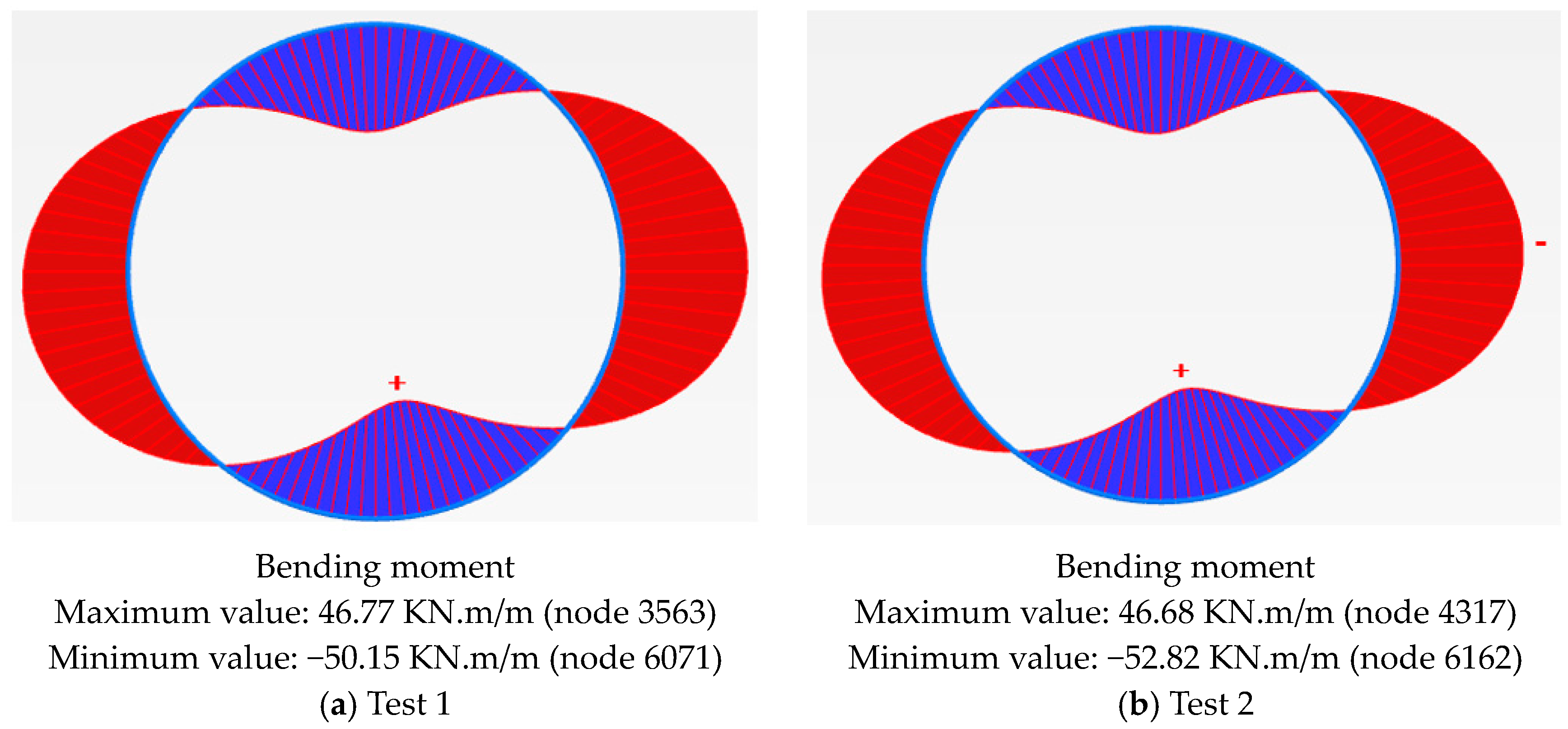
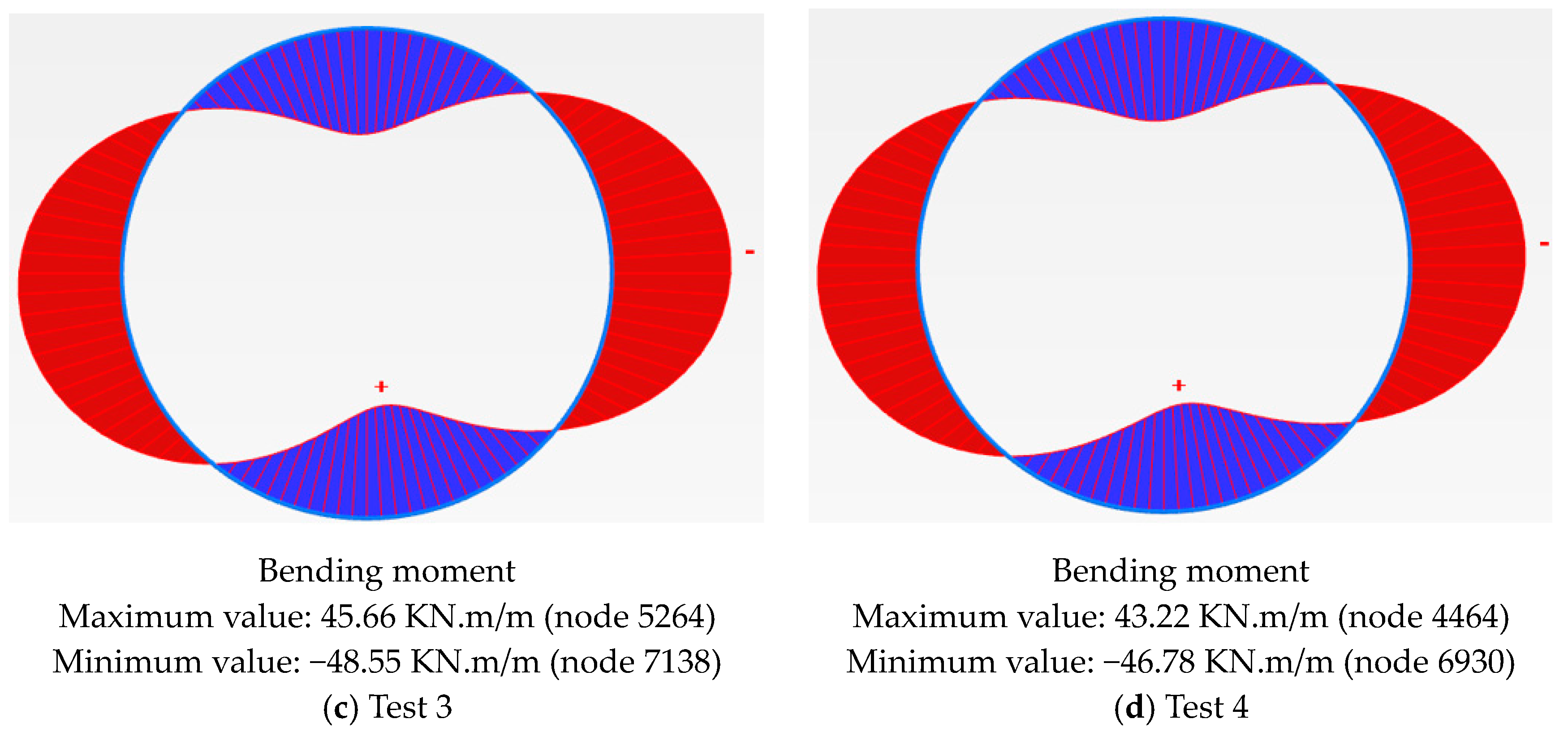
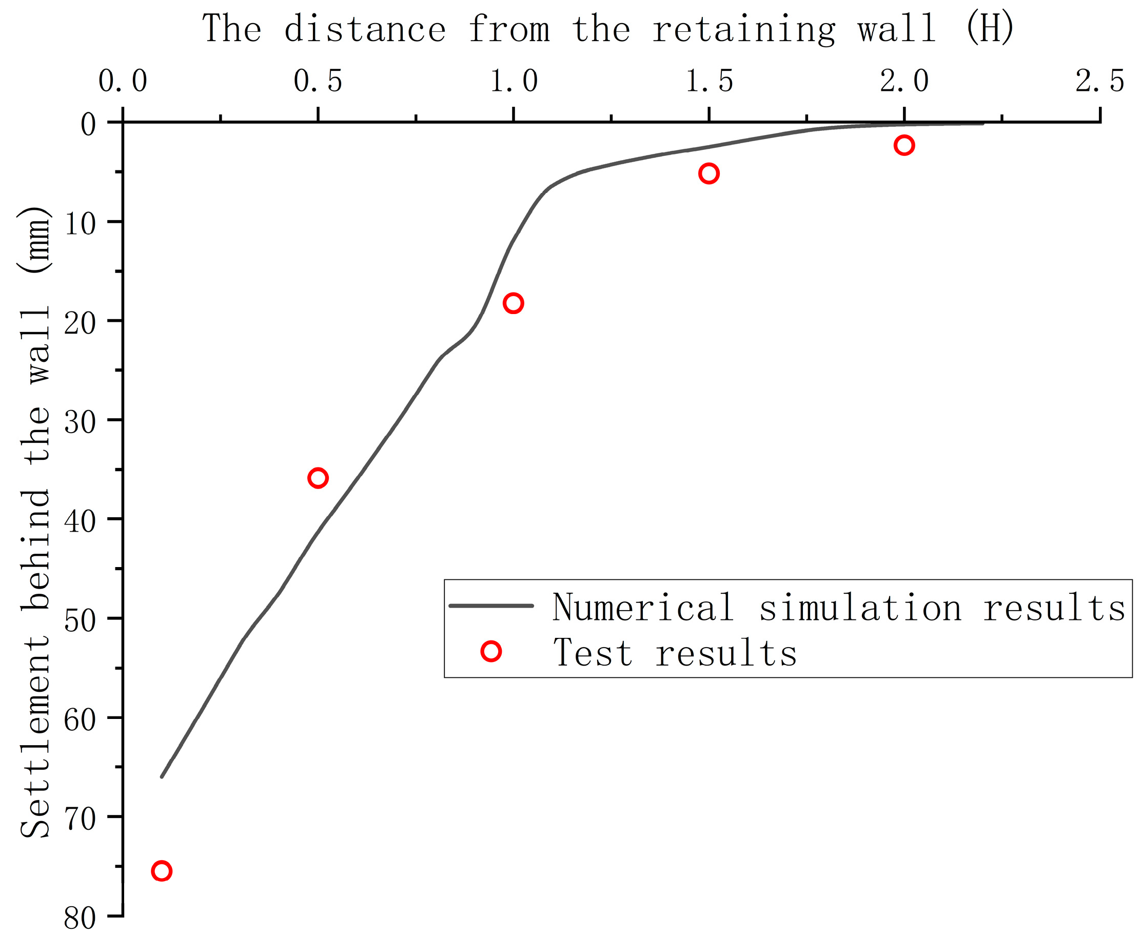
In order to provide a preliminary data reference for the test, a preliminary numerical simulation of the test using the two-dimensional finite element software PLAXIS 2D was conducted. The model was calculated by the prototype size under the constant gravity field, as shown in Figure 3a. The overall size of the model is 25 m × 20 m, and the detailed structural dimensions are shown in Section 2.1. The specific meshing is shown in Figure 3b. In the model, the boundary conditions are completely fixed deformation at the bottom, free deformation at the top, and normal fixation at the left and right boundaries.
The small strain hardening model (HSS) in the PLAXIS was selected as the constitutive model of the soil in this model. The values of parameters in the constitutive model mainly was selected according to the former studies [21,22], as shown in Table 2. In the table, Eoed is the tangent stiffness for primary oedometer loading, E50 is the secant stiffness in the standard drained triaxial test and Eur is the unloading/reloading stiffness. φ is the angle of internal friction and ψ is the angle of dilatancy. m is the power for stress-level dependency of stiffness and Rf is the failure ratio qf/qa. G0 is the initial or very small-strain shear modulus and the shear strain level γ0.7 at which the secant shear modulus Gs is reduced to about 70% of G0.
In addition, the retaining wall, tunnel lining and partition wall in the model were simulated by the plate element with linear elastic concrete material. The Poisson’s ratio was 0.2 and the elastic modulus was 30 GPa.
The basic phases in finite element analysis were as follows: initial ground stress; clear initial displacement, activate tunnel structure and remove soil in tunnel; clear initial displacement and activate retaining structure; clear initial displacement and excavate to the bottom.

2.3. Result

In Figure 4, the curves of the maximum horizontal displacement of the retaining wall and the maximum surface settlement behind the wall were drawn under different test groups. The results show that the trends of the two curves are basically the same. The displacement values of test 1 (control group), test 2 and test 4 are basically similar. In contrast, the displacement in test 3 decreases significantly. The values decrease by 19.67% and 14.84%, respectively, compared to that in the control group. This means that the partition pile in test 2 and test 4 do not play a role in reducing these two kinds of displacement. The total length of the partition pile in test 3 is 16 m, which is located above and below the influence area of excavation displacement and worked in reducing these two kinds of displacement.
In Figure 5, the maximum horizontal and vertical displacements of the tunnel under different test groups were plotted. It was shown that the vertical displacement of the tunnel in the test group is smaller than that in the control group, and the effect of embedded partition pile in test 4 is the most obvious. However, for the horizontal displacement of the tunnel, compared with the control group, the maximum displacement in test 2 and test 3 with the non-embedded partition piles has increased. Only the embedded partition pile in test 4 played a positive role in controlling the horizontal displacement of the tunnel.
The specific tunnel displacement values show that the tunnel displacement values are too small. The actual displacement measurement is difficult because of the particularity of the centrifuge model test. Therefore, in the design of the sensor, it is necessary to use a very high-precision displacement sensor to ensure the accuracy of the test results.
Figure 6 shows the displacement nephogram of the field of the soil outside the excavation, from which it can be seen that the soil behind the wall is sliding towards the interior of the excavation and the soil at the bottom is heaving upward. It is basically consistent with the research of Zheng et al. [2].
Figure 7 shows the maximum bending moment and variation curve of the circumferential bending moment of the tunnel in different test groups. The results show that the bending moment curves of the tunnel are basically the same in the four groups of tests. Compared with the control group, the partition pile in test 2 has almost no effect on reducing the bending moment of the tunnel, and even increases the bending moment of the arch waist on both sides. The partition piles in test 3 and test 4 reduce the bending moment of the tunnel, and especially the embedded partition pile in test 4 has the best effect.
In order to verify the reliability of the numerical simulation results, a pre-test was carried out before the formal test. The working condition of the pre-test is the same as that of the control group, and the feasibility of the liquid discharge system is fully verified. Due to the uncertainty of the displacement monitoring scheme of the tunnel and the retaining wall, the pre-test only uses the laser displacement sensor to measure the settlement behind the wall. Figure 8 shows the comparison of settlement between the results of the test and the results of the numerical simulation. It can be seen that the general pattern of the two curves is similar, which shows the rationality of the numerical analysis model and soil constitutive parameters, and lays a reliable foundation for the follow-up test scheme optimization.

3. Design of the Centrifuge Model Test

3.1. Layout of Test Materials and Components

In this test, Japanese Toyoura sand will be selected to prepare the foundation with the “artificial sand rain” method. The falling distance is 0.5 m and the dry density of the soil is about 1.50 g/cm3. Since the test is a two-dimensional excavation, the partition pile, tunnel and retaining wall in the model will be pre-embedded in the soil layer and arranged along the whole width of the model box in the process of preparing the foundation soil.
Magnesium-aluminum alloy will be selected to simulate the retaining wall, partition pile and tunnel. The thickness of the retaining wall and the tunnel lining is 500 mm and 200 mm. The test will use the partition wall to simulate the partition piles. The equivalent bending stiffness method is used to calculate the thickness of the partition wall as 300 mm. The model box profile and other dimensions are shown in Figure 9. In addition, the similar relationship of the parameters in the centrifuge model test is shown in Table 3. EVA sponge tape is pasted on both sides of the retaining wall, partition wall and tunnel, and Vaseline is smeared on the sponge to ensure that the edge of the structure can slide freely in the vertical direction without the leakage of sand.

3.2. Sensor Arrangement

This test mainly will focus on the tunnel displacement caused by the excavation under the protection of partition piles. The measurement targets mainly include vertical displacement of the tunnel, horizontal displacement of the tunnel, horizontal displacement of the retaining wall, tunnel internal force and settlement behind the retaining wall.
The digital image correlation (DIC) technology will be used to measure the horizontal displacement, vertical displacement of the tunnel and horizontal displacement of the retaining wall. The left and right arch waist, vault and arch bottom of the tunnel will be taken as the measuring points. The depths of the retaining wall are 0, 80, 160, 240 and 320 mm as the measuring point of the horizontal displacement. The internal force and strain of the tunnel will be measured by arranging a half-bridge strain gauge, which is used to measure the circumferential bending moment of the tunnel monitoring section. In the test, the laser displacement sensor will be used to measure the surface settlement. The white plastic sheet with grooves is fixed at the measured point on the surface to reflect the laser. As shown in Figure 8, five monitoring points will be set up behind the retaining wall corresponding to the middle section of the longitudinal tunnel, which are, respectively, located at 0.1 H, 0.5 H, 1.0 H, 1.5 H and 2.0 H (H is the excavation depth).

3.3. Test Procedure

In this test, the excavation will be simulated by discharging heavy liquid. The heavy liquid uses a ZnCl2 solution with the same soil density. In each group of tests, the heavy liquid is guaranteed to be used repeatedly, which well reflects the concept of sustainable development of green environmental protection.
The steps are as follows: (1) the preparation of the soil foundation and the arrangement of components and the installation of sensors, (2) excavate the soil to the predetermined bottom and lay silica gel bags in the excavation and pour in the heavy liquid, (3) start the centrifuge and turn it to 50× g. After the data in each sensor is stable, discharge the heavy liquid (the discharge speed of the heavy liquid is equivalent to the excavation speed in the prototype). (4) After the excavation is completed and the data in each sensor is stable, gather the data and then stop.

4. Optimization of the Test Design

4.1. Selection of Test Materials

In the former research, the materials used in the model test were basically aluminum, steel, plastic and so on [15,16,17,18]. Considering the particularity of the centrifuge model test, the size and geometric characteristics of components should be chosen following a certain similarity ratio. When the elastic modulus of the model material is not consistent with that of the actual material, the size in the model was usually obtained by equivalent conversion. The converted size of the material is too small to make the model components many times. In this centrifuge model test, magnesium-aluminum alloy was used to make components innovatively, as shown in Figure 10.
The experimental results showed that the alloy has good machinability and is not easy to rust. Through the static test, it was found that magnesium-aluminum alloy belongs to the metal material without an obvious yield platform. There was no obvious boundary between the linear elastic stage and the strengthening stage, as shown in Figure 5. By selecting the straight line in the first half of the curve for data processing, the elastic modulus of the material was about E = 40 GPa. After processing, the elastic modulus could basically reach 30 GPa, which was close to that of the common reinforced concrete. The tensile strength was about 185 MPa and the elongation rate was about 3–10%. According to the result of the performance testing, the alloy had good physical and mechanical properties. Using magnesium-aluminum alloy as material to make structural members had the following two advantages: first, the elastic modulus was close to concrete, and the size of model members could be calculated directly according to the geometric similarity ratio; second, it could simulate the actual project more accurately and make the test more authentic.

4.2. Excavation Simulation

In this centrifuge model test, the method of discharging heavy liquid in the centrifuge process will be used to simulate excavation. This method has the advantages of simulating excavation under operating conditions and controllable excavation speed. Before the test, the sand has been prepared by artificial sand rain method, and the dry density of soil was about 1.50 g/cm3. The heavy liquid will adopt a ZnCl2 solution with the same density as the dry sand soil. The solution with the target density will be prepared by solid ZnCl2 according to the ratio. After calculation, the molar density needed to prepare the solution is 3.67 mol/L, and the test requires 2.56 L of solution in total.
The heavy liquid discharge system used in the test mainly includes a discharge rubber tube, heavy liquid collection box, solenoid valve, flow control valve, silicone bag and so on. The solenoid valve will be responsible for remotely controlling the opening and closing of heavy liquid discharge. The flow control valve will be used to control the discharge speed and to simulate the real excavation speed of the actual project. The silicone bag will be installed at the bottom of the excavation and fixed on the inner surface of the excavation. The bottom of the bag will be connected to the discharge rubber tube. The side of the model box will be perforated and the discharge tube will be led into the heavy liquid collection box. In order to prevent the discharge of liquid from being unsmooth in the process of centrifugation, the height of the heavy liquid collection box should be reduced as much as possible. Finally, the PP (Polypropylene- a plastic material resistant to chemical corrosion) box of 80 mm × 400 mm × 100 mm will be selected as the heavy liquid collection box, and the bottom of the box and the base of the centrifuge will be fixed by bolts. The specific installation location is shown in Figure 11.

4.3. Optimization of Measurement

According to the preliminary numerical simulation, the horizontal and vertical displacements of the tunnel are roughly 3–7 mm. If converted to the model test, the tunnel displacement is roughly 0.06–0.14 mm, and the measurement accuracy needs to reach 0.01 mm. The general displacement measurement sensor can not achieve such high accuracy. In addition, the settlement of the pre-test also shows that the model displacement of soil and structure is very small.
The laser displacement sensor has high accuracy and is responsible for measuring the surface settlement behind the wall in this test. However, it is difficult to install in tunnel measurement. Therefore, in this test, digital image correlation (DIC) technology will be selected to measure tunnel displacement. It needs to mark points on the surface of the tunnel and the retaining wall in the glass side of the model box. When shooting, it is necessary to ensure that the camera is stable and perpendicular to the glass side of the model box to guarantee the accuracy of the later data. Finally, the image can be imported into the MATLAB program for analysis. The principle of DIC measurement technology is to import the images taken during the experiment into the MATLAB program. The pixel coordinates on the marked points in the initial image are identified by a special algorithm, and then the changed coordinates are automatically identified in other images. Thus the displacement value of the marked points in the experiment is obtained. In theory, the higher the resolution of the picture, the higher the displacement accuracy of the DIC calculation.
In order to meet the requirement of high accuracy, a high pixel camera was prepared to photograph the test process (Figure 12). Considering the camera bracket and the size of the model box, this test chose a 48-megapixel Shan Gou A8 camera with a size of 26 mm × 40 mm × 60 mm.
In order to ensure the accuracy of the subsequent test data, the DIC measurement accuracy test was carried out. Firstly, fix the Vernier caliper on the desktop, mark its surface, and fix the camera perpendicular to the Vernier caliper. Secondly, the mobile phone is used for the remote control to shoot the Vernier caliper before and after displacement respectively. Finally, the two photos are imported into the MATLAB program for calculation, and the test photos are shown in Figure 13.
The calculation result in the DIC program is in pixels. After calculation, the lateral displacement value at the mark point is 1.57 pixels. The actual lateral size of the photo is 273 mm, and the lateral pixel value is 3072. The final calculated displacement value is (273÷3072) × 1.57 = 0.1395 mm. Compared with the 0.14 mm displayed by the Vernier caliper, the error is 0.36%, which can meet the accuracy requirements of the test.

5. Conclusions

In this paper, the centrifuge model test design and optimization of the deformation of the adjacent existing tunnel caused by the excavation in terms of the partition pile under the dry sand are conducted by the numerical analysis. The main contents and conclusions are as follows:
(1)
In the test, the magnesium-aluminum alloy materials were used to model the structural members, and its elastic modulus was close to that of common reinforced concrete, which can simulate the actual project more accurately.
(2)
Due to the high accuracy of tunnel displacement measurement, the high accuracy digital image correlation (DIC) was selected to measure the horizontal and vertical displacement of the tunnel.
(3)
In this test, the excavation was simulated by discharging the ZnCl2 solution, and the actual excavation speed was simulated by a flow control valve.
(4)
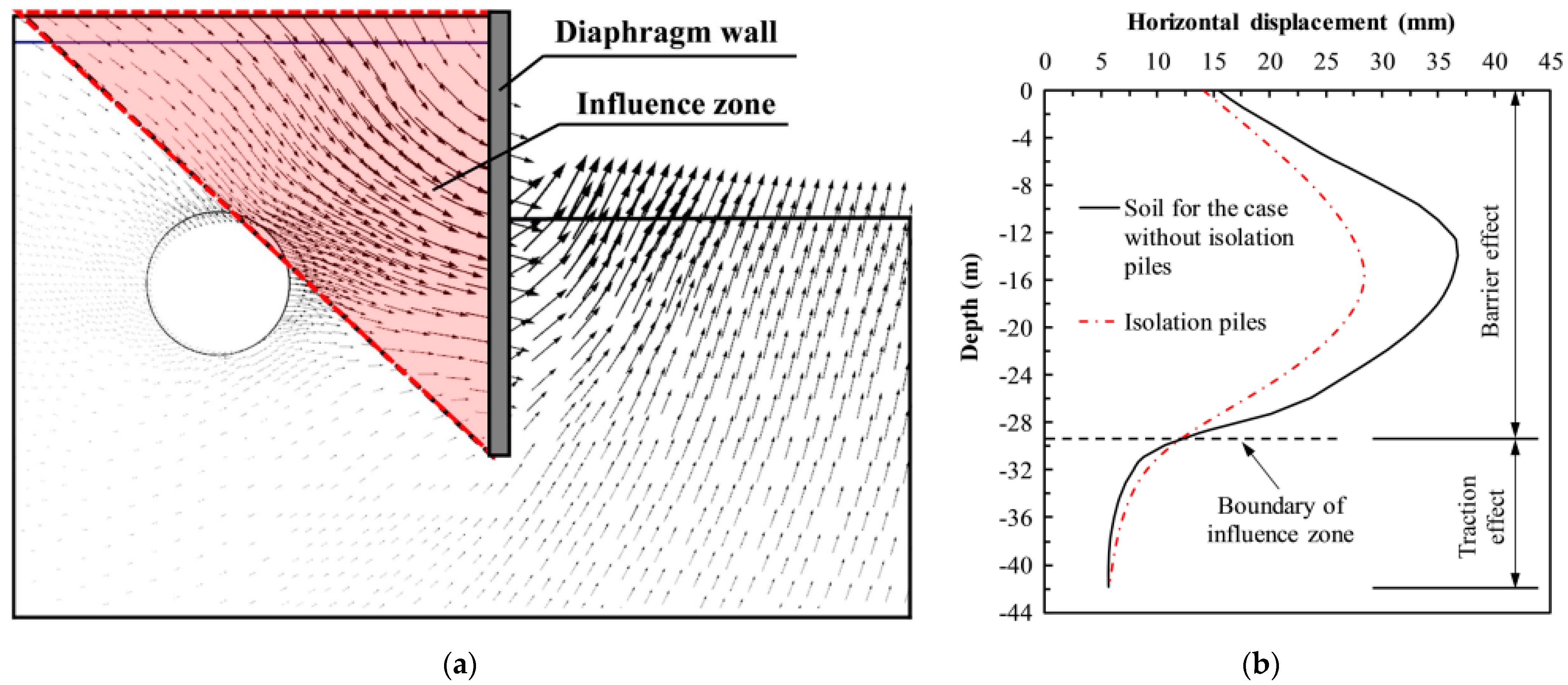
The numerical simulation results show that the embedded partition piles can play a better role in controlling the displacement and internal force of the tunnel than the non-partition piles and the non-embedded partition piles. Numerical simulation results provide a basis for the design of centrifuge model experiments.

Author Contributions

Conceptualization, B.W.; methodology, B.W., Y.D. (Yiming Du) and Y.D. (Yu Diao); software, B.W. and X.Z.; investigation, B.W. and Y.D. (Yiming Du); data curation, B.W.; writing—original draft preparation, B.W.; writing—review and editing, Y.D. (Yiming Du) and Y.D. (Yu Diao); funding acquisition, Y.D. (Yiming Du). All authors have read and agreed to the published version of the manuscript.

Funding

This research was funded by the National Natural Science Foundation of China (grant number: 52008293).

Institutional Review Board Statement

Not applicable.

Informed Consent Statement

Not applicable.

Data Availability Statement

Data openly available in a public repository.

Conflicts of Interest

The authors declare no conflict of interest.

References

  1. Zheng, G.; Wang, F.J.; Du, Y.M.; Diao, Y.; Lei, Y.W.; Cheng, X.S. The Efficiency of the Ability of Isolation Piles to Control the Deformation of Tunnels Adjacent to Excavations. Int. J. Civ. Eng. 2018, 16, 1475–1490. [Google Scholar] [CrossRef]
  2. Ying, H.W.; Li, T.; Yang, Y.W. Analysis on the effect and engineering application of protecting adjacent buildings with partition wall of deep excavation. Chin. J. Geotech. Eng. 2011, 33, 1123–1128. [Google Scholar]
  3. Ma, S.K.; Fu, X.X.; Lu, H.; Huang, Z.; Zhang, J.B. A combined support method of partition pile and diaphragm wall for protection of buildings adjacent to deep excavation. Arab. J. Geosci. 2021, 14, 2005. [Google Scholar] [CrossRef]
  4. Marta, D. Tunnel complex unloaded by a deep excavation. Comput. Geotech. 2001, 28, 469–493. [Google Scholar]
  5. Shi, J.W.; Ng, C.W.W.; Chen, Y.H. Three-dimensional numerical parametric study of the influence of basement excavation on existing tunnel. Comput. Geotech. 2015, 63, 146–158. [Google Scholar] [CrossRef]
  6. Zheng, G.; Du, Y.M.; Diao, Y. Optimization analysis of deformation control of existing tunnel outside excavation by partition pile. Chin. J. Rock Mech. Eng. 2015, 34, 3499–3509. [Google Scholar]
  7. Chen, R.P.; Meng, F.R.; Li, Z.C.; Ye, Y.H.; Hu, Q. Excessive displacement and protective measures of metro tunnel near deep excavation. J. Zhejiang Univ. (Eng. Ed.) 2016, 50, 856–863. [Google Scholar]
  8. Xu, X.B.; Hu, Q.; Zeng, L.B.; Wang, J.C.; Wang, Z. Model experimental study on the influence of partition pile on side tunnel of excavation in dry sand foundation. Chin. J. Rock Mech. Eng. 2020, 39, 3015–3022. [Google Scholar]
  9. Wei, H.W.; Yang, F.; Luo, W.; Kui, Y.; Lu, Z. Model experimental study on the influence of excavation on the existing tunnel on the side. J. Shandong Constr. Univ. 2020, 35, 15–22. [Google Scholar]
  10. Zeng, X.X.; Ding, W.X.; Peng, L.; Xu, C.J. Deformation analysis of partition pile position on adjacent existing metro tunnel during deep excavation. Chin. Sci. Technol. Eng. 2017, 17, 296–301. [Google Scholar]
  11. Fu, Z.F.; Yi, Y.L.; Zhou, W.S.; Pan, H.B.; Luo, X.D. Influence of parameters of external partition pile in excavation on deformation of adjacent existing metro tunnel. Chin. Saf. Environ. Eng. 2021, 28, 57–63. [Google Scholar]
  12. Xu, C.J.; Zhu, H.L.; Long, L.B.; Jiang, Y.L.; Hu, Q. Analysis of protection effect of deep excavation using partition pile on existing tunnel outside the pit. Chin. Disaster Prev. Control. Tunn. Undergr. Eng. 2019, 1, 119–126. [Google Scholar]
  13. Cheng, Y.C.; Gong, D.K.; Ye, J.N.; Zheng, X. Analysis of partition effect of partition pile outside excavation on horizontal displacement of soil. Chin. J. Disaster Prev. Mitig. Eng. 2019, 39, 478–486. [Google Scholar]
  14. Xu, C.J.; Zeng, X.X.; Qi, X.K.; Zhao, X.S.; Peng, L. Study on protection effect of arched double-row partition piles on existing tunnel. Chin. J. Disaster Prev. Mitig. Eng. 2018, 38, 633–641. [Google Scholar]
  15. Gong, C.; Kang, L.; Liu, L.; Lei, M.; Ding, W.; Yang, Z. A novel prediction model of packing density for single and hybrid steel fiber-aggregate mixtures. Powder Technol. 2023, 418, 118295. [Google Scholar] [CrossRef]
  16. Zhou, H.; Hu, Q.; Yu, X.; Zheng, G.; Liu, X.; Xu, H.; Yang, S.; Liu, J.; Tian, K. Quantitative bearing capacity assessment of strip footings adjacent to two-layered slopes considering spatial soil variability. Acta Geotech. 2023. [Google Scholar] [CrossRef]
  17. Ng, C.W.W.; Shi, J.W.; Chen, Y.H. Three-dimensional centrifuge modelling of basement excavation effects on an existing tunnel in dry sand. Can. Geotech. J. 2013, 50, 874–888. [Google Scholar] [CrossRef]
  18. Huang, X.; Huang, H.W.; Zhang, D.M. Centrifuge modelling of deep excavation over existing tunnels. Proc. Inst. Civ. Eng.-Geotech. Eng. 2014, 167, 3–18. [Google Scholar] [CrossRef]
  19. Song, G.Y.; Marshall, A.M. Centrifuge study on the use of protective walls to reduce tunnelling-induced damage of buildings. Tunn. Undergr. Space Technol. 2021, 115, 104064. [Google Scholar] [CrossRef]
  20. Chen, R.P.; Ashraf, A.; Meng, F.Y. Centrifuge model test study on the influence of excavation on side tunnel and the action of partition wall. Chin. J. Geotech. Eng. 2018, 40, 6–11. [Google Scholar]
  21. Finno, R.J.; Calvello, M. Supported Excavations: Observational Method and Inverse Modeling. J. Geotech. Geoenviron. Eng. 2005, 131, 826–836. [Google Scholar] [CrossRef]
  22. Schanz, T.; Vermeer, P.A. On the Stiffness of Sands. In Pre-Failure Deformation Behaviour of Geomaterials; Thomas Telford Publishing: London, UK, 1998; pp. 383–387. [Google Scholar]
Figure 1. (a) Soil displacement vector field after the excavation; (b) comparison of the displacement curves of the isolation piles and soil in cases with and without isolation piles [1].
Sustainability 15 08353 g001
Figure 2. Geotechnical centrifuge photos.
Sustainability 15 08353 g002
Figure 3. Numerical simulation model and meshing of the model (test 4).
Sustainability 15 08353 g003
Figure 4. The variation of horizontal displacement of the retaining wall and settlement behind the wall.
Sustainability 15 08353 g004
Figure 5. The variation of maximum horizontal and vertical displacement of the tunnel.
Sustainability 15 08353 g005
Figure 6. The displacement nephogram of soil in the site.
Sustainability 15 08353 g006
Figure 7. Tunnel circumferential bending moment of different tests.
Sustainability 15 08353 g007aSustainability 15 08353 g007b
Figure 8. Settlement obtained by test and numerical simulation.
Sustainability 15 08353 g008
Figure 9. Model box profile.
Sustainability 15 08353 g009
Figure 10. Magnesium-aluminum alloy plate and its stress-strain curve.
Sustainability 15 08353 g010
Figure 11. Installation diagram of heavy liquid discharge device.
Sustainability 15 08353 g011
Figure 12. Shooting equipment of DIC (Shenzhen Yuanpai Digital Co., Ltd., Shenzhen, China).
Sustainability 15 08353 g012
Figure 13. The photos of DIC accuracy test.
Sustainability 15 08353 g013
Table 1. Test scheme table.
Test NumberBuried Depth at the Top of PilePile Length
1 (Control group)00
208
3016
4816
Table 2. Parameters of HSS Model of Toyoura Sand.
Eoed
/MPa
E50
/MPa
Eur
/MPa
mG0
/MPa
γ0.7φ/(°)ψ/(°)Rf
33.1733.1799.510.6999.513 × 10−436.1256.1250.91
Table 3. Parameter similarity ratio of centrifuge model test (model/prototype).
Physical QuantitySymbolicDimensionalSimilarity
Ratio
Physical QuantitySymbolicDimensionalSimilarity
Ratio
Gravitational accelerationgL·T−250StressσM·T−2·L−11
Geometric dimensionLL1/50Elastic modulusEM·T−2·L−11
DisplacementDL1/50Bending stiffnessEIM·T−2·L31/504
DensityρM·L−31Bending stiffness per unit lengthEI unitM·T−2·L21/503
TimeTT1/502Bending momentMM·T−2·L21/503
Strainε-1Bending moment per unit lengthM unitM·T−2·L1/502
Disclaimer/Publisher’s Note: The statements, opinions and data contained in all publications are solely those of the individual author(s) and contributor(s) and not of MDPI and/or the editor(s). MDPI and/or the editor(s) disclaim responsibility for any injury to people or property resulting from any ideas, methods, instructions or products referred to in the content.

