Article

Modeling and Dynamic Impact Analysis of Prismatic Lithium-Ion Battery

School of Mechanical and Power Engineering, Zhengzhou University, Zhengzhou 450001, China
*
Author to whom correspondence should be addressed.
Sustainability 2023, 15(10), 8414; https://doi.org/10.3390/su15108414
Submission received: 23 April 2023 / Revised: 17 May 2023 / Accepted: 21 May 2023 / Published: 22 May 2023
(This article belongs to the Special Issue Intelligent Technologies in Energy Management of New Energy Vehicle)

Abstract

:
Battery modules of new energy vehicles are frequently exposed to dynamic impacts during traffic accidents. However, current research on the mechanical safety of prismatic lithium-ion batteries (PLIBs) primarily focuses on quasi-static states, and the failure mechanism of batteries under dynamic impact remains incompletely understood. Therefore, to investigate the failure mechanism and critical failure displacement of PLIB under dynamic impacts, this study establishes a computational model of PLIB considering anisotropy based on experimental data and extends the simulation to the case of high-velocity battery collision. On this basis, the deformation feature, mechanical response, and failure mechanism of PLIB under different impact velocities are analyzed. The results show that the deformation feature of PLIB under dynamic impact differs from that under quasi-static loading. As the loading velocity increases, the inertial effect gradually becomes apparent, causing the deformation of PLIB to localize and the failure displacement to decrease. Three critical failure displacements were identified within the velocity range of 0–20 m/s. This study can serve as a reference for battery safety design.

1. Introduction

Lithium-ion batteries (LIBs) are highly preferred in the new energy vehicles industry due to their numerous advantages such as high energy density, extended service life, high output power, and excellent environmental adaptability [1,2,3]. However, the active electrochemical reaction of lithium-ion batteries also makes them more susceptible to dangerous accidents. Therefore, the design of electric vehicles must prioritize not only the safety of occupants in the event of a collision but also the unique safety concerns related to the vehicle’s battery. According to studies, battery mechanical failures account for almost one-third of electric vehicle safety accidents [4], with deformation caused by scratches or collisions of the battery pack being a common culprit. This can lead to destructive failure of the battery, resulting in a burning or exploding electric vehicle [5,6,7,8]. However, in the published literature, the mechanical integrity of PLIBs has been studied mostly for cylindrical batteries and quasi-static conditions, and the failure mechanism of PLIBs caused by mechanical collision is not clear. As prismatic lithium-ion batteries are increasingly being used, it is crucial to investigate their mechanical integrity under dynamic impact.
Sahraei et al. [9,10,11,12,13,14] conducted experiments to determine the mechanical properties of electrode materials and diaphragms in cylindrical and pouch batteries. They then used these data to establish finite element models of batteries of varying sizes, using isotropic compressible foam materials as homogenized model equivalents. This allowed them to predict the occurrence of short circuits in radial compression under different operating conditions. Li Wei et al. [15,16,17] conducted experiments to explore the failure mode of LIBs due to mechanical abuse, analyzed the correlation between internal short circuits and changes in-open circuit voltage and temperature, and determined that the inflection point on the force–displacement curve marks the start of internal damage. Additionally, the constituent materials of jellyrolls were tested and characterized, and an accurate battery model was developed to predict short circuits under axial compression. Wang et al. [18] developed a detailed model based on the 18650 cylindrical batteries that can effectively anticipate short-circuiting faults caused by mechanical failures. Another model was also developed to capture the explosion behavior of the battery following a short circuit [19]. Xu et al. [20] proposed a model for the 18650 cylindrical battery that is anisotropic and homogeneous, taking into account the effects of SOC. The model used the unified strength theory to predict the internal short circuit in the battery. Wang et al. [21] tested the effect of various SOC levels on prismatic batteries when subjected to compression loads, and the response curves were similar; in addition, a finite element model was developed to predict the mechanical properties of PLIBs.
The above studies primarily focus on the mechanical properties of LIBs under quasi-static conditions, but the mechanical properties and damage tolerance of LIBs subjected to dynamic impacts in actual vehicle accidents may be different from quasi-static conditions. To improve the crashworthiness of vehicles under dynamic impact and guide the safety protection design of battery packs [22], more research has begun to focus on the mechanical response of LIBs under dynamic impact [23,24,25,26,27]. Chen et al. [28,29] conducted drop-hammer tests on PLIBs with a round indenter and a flat indenter to discuss the effects of the strain rate and SOC on the mechanical properties of PLIBs, and found that the structural stiffness of the PLIBs increased with an increasing strain rate but was barely affected by SOC. Pan et al. [30] started with mechanical testing and calibration of the pouch battery assembly material and developed a detailed model with optimized material parameters to investigate the dynamic response of the battery under dynamic shock conditions. Zhu et al. [31] developed a model of the pouch battery and analyzed the factors contributing to resistance enhancement under dynamic loading. Their findings suggest that the strain rate effect primarily comes from the electrolyte. Jia et al. [32] revealed the mechanical and electrical coupling behavior of pouch LIBs under dynamic loading through drop hammer tests and concluded that the deformation of the battery components and material failure together determine the electrical performance of the battery and higher loading rates result in faster voltage drops. Xia et al. [33] conducted finite element simulations of electric vehicle battery pack collisions with ground obstacles, providing important clues for the design of ground impact protection structures for battery packs. Wang et al. [34] tested the dynamic mechanical response of 18650 cylindrical batteries with different SOCs by the drop-hammer test, developed a new anisotropic model considering the SOC effect, and proposed a failure criterion based on the equivalent plastic strain of jellyroll.
The mechanical behavior of PLIB under quasi-static conditions has been extensively studied. However, in real-life scenarios such as vehicle crashes, the batteries are exposed to dynamic impact that may result in different mechanical behavior and failure mechanisms. Therefore, it is important to investigate the behavior of PLIB under dynamic impact to better understand their performance and ensure their safety in such situations. In this paper, the compression experiments of PLIB are first carried out under quasi-static conditions, and a homogenized numerical model of the PLIB is then developed and its accuracy is verified by comparing it with the experimental results. The numerical model is further extended to dynamic loading to obtain the dynamic responses of PLIB under different impact velocities. Finally, the dynamic deformation features and the dynamic failure modes of the PLIB at different velocities are analyzed. These findings provide meaningful insights into the safety design of battery packs.

2. Experiments

2.1. Experimental Specimen

This study utilizes the prismatic lithium-ion battery, as illustrated in Figure 1. The PLIB consists of an aluminum shell, jellyroll, and electrolyte. The jellyroll includes the anode, cathode, and diaphragm, which are stacked and wound together before being immersed in the electrolyte. The dimensions of the PLIB are 148 mm × 91 mm × 26.5 mm, with a weight of 0.654 kg. The nominal voltage and capacity are 3.2 V and 20 Ah, respectively, with a cut-off voltage of 2.5~3.65 V. Additional parameters can be found in Table 1.
The PLIB shown in Figure 1 was used as the experimental object and experimental schemes of plane compression and local compression were designed separately. Plane compression experiments were conducted using a flat indenter, while the local compression experiments were conducted using a cylindrical indenter (R = 25 mm). Figure 2 depicts the loading directions of the compression experiments. The plane compression experiments were carried out in three loading directions: The through-thickness direction (TTD), transverse direction (TD), and machine direction (MD), and the local compression experiments were performed in the through-thickness direction (TTD) only.

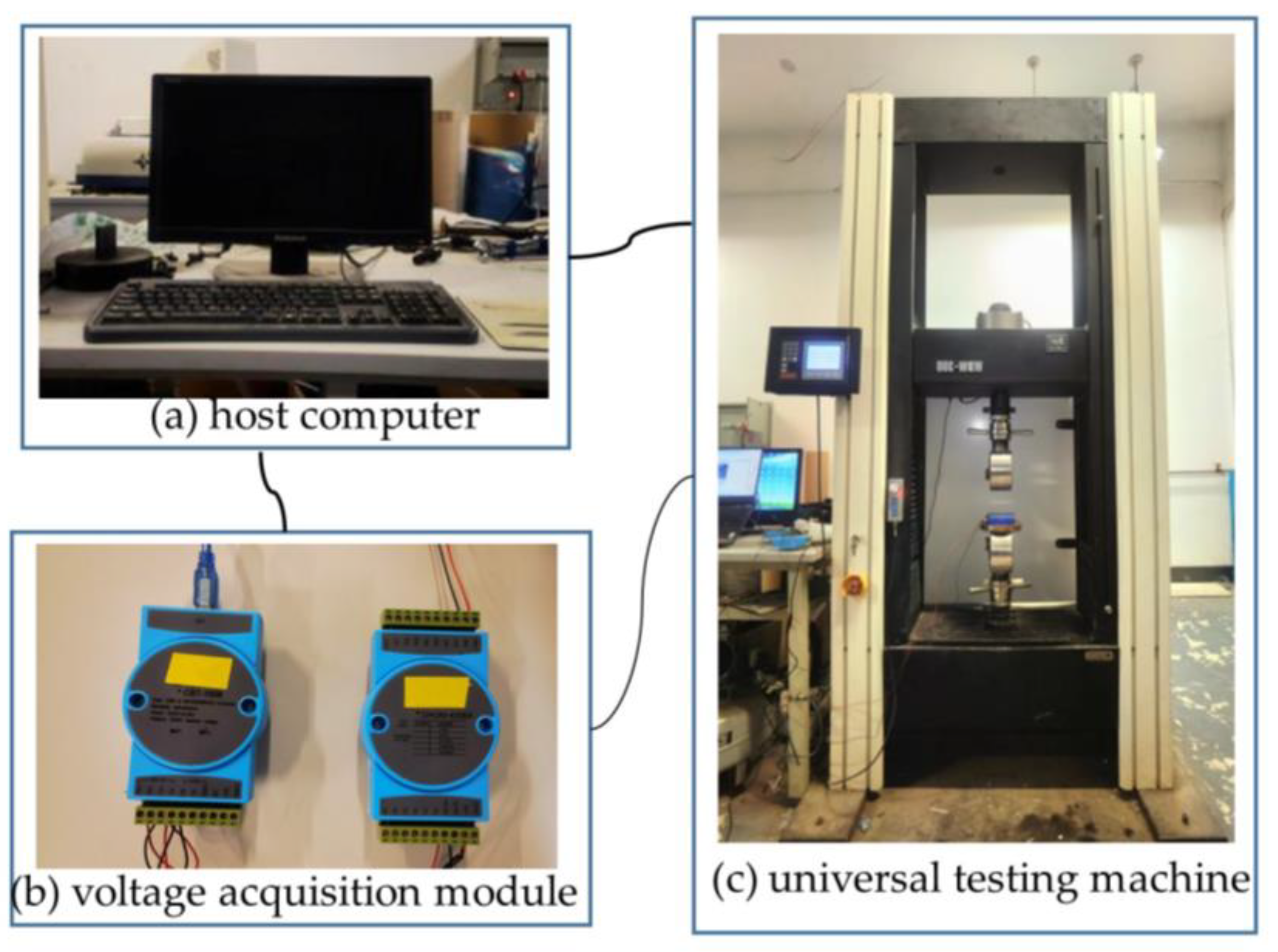
2.2. Experimental Setups

The experiments were conducted using a WDW-300 microcomputer-controlled universal testing machine with a test force range of 0–300 kN and a displacement rate range of 0.005–250 mm/min. The relative error of test force and displacement was ±0.5%. The loading velocity for plane compression and local compression experiments was set at 1 mm/min. Before compression testing, the batteries were discharged to 2.8 V at a discharge rate of 1 C on the charge–discharge test bench and left for a period of time to ensure safety during testing. Battery voltage was monitored during the experiment to detect any short circuits. Each experiment was repeated twice to ensure the accuracy of the experimental data. Figure 3 illustrates the universal testing machine and voltage acquisition module used for the experiments.

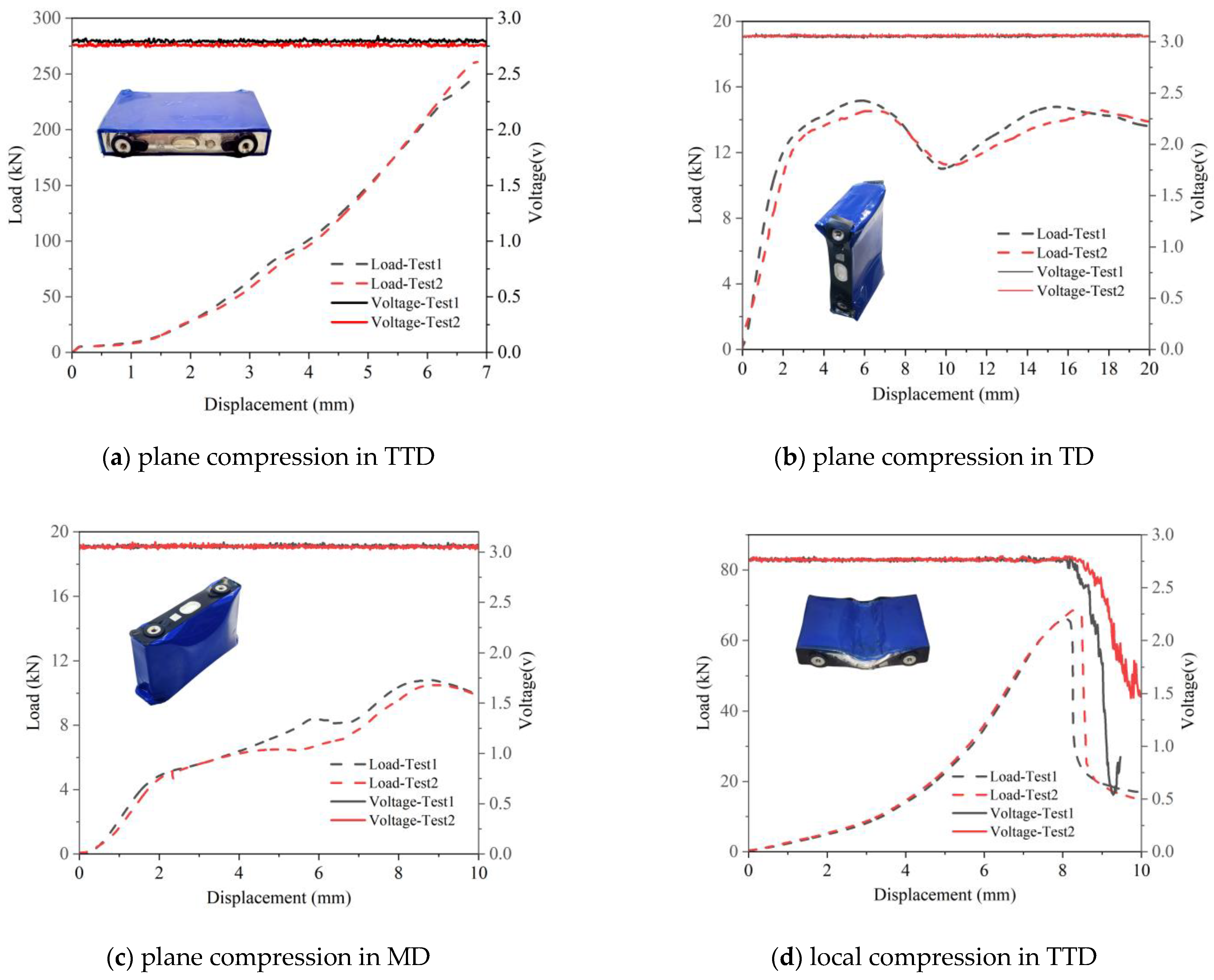
2.3. Quasi-Static Compression Experiment and Result Analysis

Figure 4a shows the results of plane compression experiments on prismatic lithium-ion batteries in the through-thickness direction. During the compression process, plastic deformation and creasing occurred in the battery shell, but it did not crack. In addition, the voltage remained constant throughout the compression process, indicating that the PLIB was not short-circuited. Meanwhile, the load–displacement curves of the two repeated tests were basically the same, and the load gradually increased due to the compacting degree of the jellyroll gradually increasing.
Figure 4b,c show the results of plane compression experiments on PLIBs in TD and MD, respectively. In these two directions of compression, the aluminum shell of PLIB was severely deformed but neither cracked. By the curve of voltage variation with displacement, it can be found that none of the PLIB was short-circuited either. Unlike TTD compression, which increases load-carrying capacity by densifying the jellyroll, compression in MD and TD of PLIB results in poor load-carrying capacity due to jellyroll bending and instability, leading to a decrease in overall battery load-carrying capacity. The special characteristics of the jellyroll material and structure make the mechanical strength of the PLIB in the MD and TD weaker than that in the TTD, and it is more likely to deform under the compression load.
Figure 4d depicts the outcome of local compression experiments conducted on PLIBs. The whole compression process can be divided into 2 stages according to the various characteristics of load and voltage with displacement. In stage 1, the internal pore structure of the jellyroll is compressed gradually, manifested as the local stiffness of the deformation zone continuously increasing with the increase in compression intrusion, that is, the load–displacement curve’s slope continues to increase, and the voltage at this stage remains unchanged. In stage 2, as the squeeze displacement increases, the damage to the jellyroll gradually accumulates until the load reaches its peak, after which it starts to drop rapidly, while the voltage also drops abruptly, which is due to the mechanical fracture of the jellyroll, leading to the rupture of the diaphragm, and an internal short circuit occurs in the PLIB at this stage. Li Wei et al. [15] found that the inflection point of force and voltage corresponds to an abrupt change in temperature increase, which is the starting point not only for battery failure but also for thermal runaway. The displacement corresponding to the peak load point (8.1 mm) is the critical damage limit of the battery under quasi-static compression.

3. Numerical Simulation

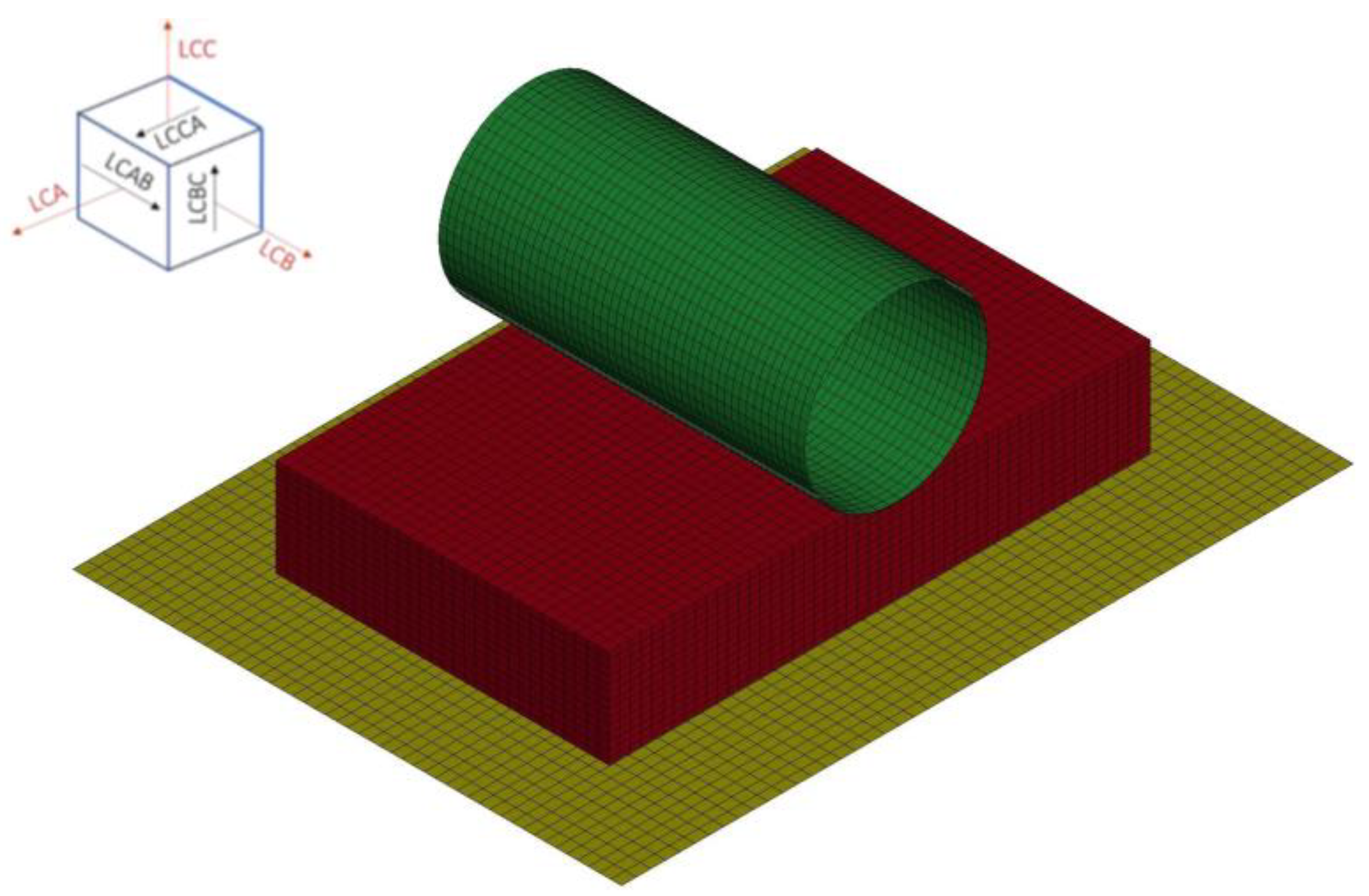
3.1. Establishment of a Computational Model

Currently, there are two main strategies for finite element modeling of LIBs: The detailed model and the homogenization model. The detailed model includes the mechanical properties of each material component, but building it is complex and time-consuming due to the micron-scale dimensions of laminated materials such as the current collector, diaphragm, and coating of the battery in the thickness direction. Additionally, it is difficult to measure and calibrate the interface properties between different component materials experimentally. As a result, it is challenging to apply the detailed model to crash simulations at the level of the whole vehicle or battery pack [18]. On the other hand, the homogenization model ignores the layered structure of the jellyroll and treats the jellyroll as a homogeneous material. It simulates the overall mechanical response of the jellyroll based on data calibrated by overall compression experiments. The homogenization model has proven to be sufficient and effective in characterizing the macroscopic mechanical response [23].
In this section, a finite element model of PLIB was established in the LS/Dyna. The PLIB is primarily composed of an aluminum shell and jellyroll. The jellyroll (consisting of an anode, cathode, diaphragm, and winding tube) of the PLIB was simplified as a homogeneous material and assembled in the aluminum shell. Figure 5 depicts the grid of the PLIB model, except for the jellyroll, which adopts a hexahedral element, while the aluminum shell and indenter all adopt shell elements.
The jellyroll of the battery is composed of the active substance, the metal collector, and the diaphragm of multiple composite materials, which are anisotropic. Therefore, the MAT_126 modified honeycomb material of LS/Dyna is adopted to simulate the anisotropic behavior of the jellyroll. MAT_126 assumes that the stress–strain responses in the three directions are independent of each other, and the user needs to define the positive stress–strain curves (LCA, LCB, and LCC) and the shear stress–strain curves (LCAB, LCBC, and LCAC) in the three material directions. The stress–strain curves in the three main directions of the jellyroll can be obtained through the following formula:
σ = F A
ε = H H 0
in which F is the loading force, A is the force-bearing area, H is the compression displacement, and H0 is the initial thickness in the compression direction.
The stress–strain curves can be fitted by the following function [13]:
σ = B ε 2
in which σ is stress, ε is strain, and B is the material parameter. Figure 6 shows the stress–strain curves obtained by experiments.
For the shear curves, it is assumed that the in-plane shear strength of the jellyroll is half of the compressive strength. Therefore, half of the maximum value of the TD curve was taken as the in-plane shear input curve [35]. On the other hand, the jellyroll has a multilayer structure, and the out-of-plane shear indicates the interlayer sliding of the internal components of the electrode, which means that the shear strength in this direction is lower, and the shear strength in this direction is assumed to be 10% of the maximum value of the MD curve [35].
In addition, the aluminum shell of the battery was simulated using MAT_24 elastic-plastic material, and the flat indenter and cylinder indenter were simulated using MAT_20 rigid body material. The specific parameter settings of material models can be found in Table 2. The contact type between the indenter, aluminum shell, and jellyroll was set to AUTOMATIC_SURFACE_TO_SURFACE. The penalty function contact algorithm is adopted, and the coefficients of static friction and dynamic friction are 0.3 and 0.2, respectively.

3.2. Model Validation

The quasi-static loading velocity was 1 m/s for the finite element simulation, and the dynamic effects can be neglected at this loading velocity [36,37]. The simulation and experimental results of plane compression and local compression are compared in Figure 7. The goodness of fitting R2 was used to indicate the degree of fitting between the simulation results and the experimental results. The values of R2 in all directions were greater than 0.8, which proves that the model can accurately describe the mechanical properties of PLIB under compression conditions. This lays a foundation for subsequent analysis of battery short-circuit faults under local compression conditions.

4. Discussion

In Section 3, a computational model of the PLIB considering anisotropy was developed on the basis of experiments and the accuracy of the model was verified. In this section, the simulation is extended to the case of high-velocities. The dynamic response and failure mode of PLIB under impact are explained by combining experimental and numerical simulation. The deformation feature, dynamic response, and failure mechanism of the prismatic battery under different impact velocities are discussed.

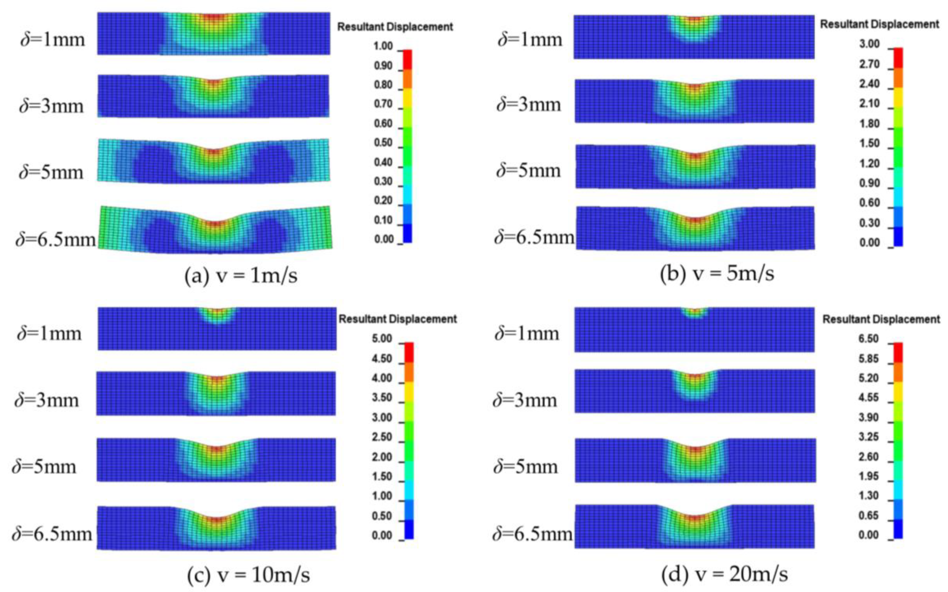
4.1. Deformation Feature of PLIB at Different Loading Velocities

Figure 8 displays the displacement cloud of PLIB when subjected to dynamic impact by the cylindrical indenter, where δ represents the displacement. The loading velocity is set between 1 m/s and 20 m/s, which represents the collision velocity range of most vehicles [8]. When the loading velocity is 1 m/s, the size of the deformation zone is basically unchanged during the whole process, and the cylindrical indenter is pressed against the center of the battery causing the sides of the battery to gradually tilt upward. However, as the loading velocity increases, the deformation zone of the battery with the same displacement becomes smaller, which means that as the loading velocity increases, the inertial effect plays a dominant role, and the deformation tends to localize. Therefore, the different deformation features under high-velocity impact may have different effects on the failure.

4.2. Dynamic Response of PLIB at Different Loading Velocities

Figure 9 shows the load–displacement curves of PLIB when subjected to the dynamic impact by the cylindrical indenter. The load–displacement curve of the PLIB under dynamic loading exhibits significant dynamic effects, which are significantly different from that under quasi-static loading. This indicates that relying only on a quasi-static calculation model cannot accurately reflect the actual response of the PLIB during vehicle accidents.
At 1 m/s, the load–displacement curve of the PLIB rises continuously, but as the impact velocity increases, the curve begins to oscillate and the structural stiffness of the PLIB increases significantly with the increase in impact velocity. This means that the load rises more rapidly with the increase in displacement, and the increase in stiffness becomes more obvious with greater velocity. In addition, the moment when the failure element first appears in the model is defined as the failure initiation point and is represented by the points in Figure 9. The load corresponding to these points is the destructive force of the PLIB, and it can be seen that the destructive force when the battery fails under dynamic loading conditions is lower than that under low-velocity conditions, which is consistent with the results of the 18650 batteries in reference [35]. As the impact velocity increases, the displacement corresponding to the failure initiation point decreases and the battery fails earlier.

4.3. Failure Analysis of PLIB at Different Loading Velocities

Unlike the uniform deformation of the PLIB under quasi-static loading, the inertial effect under dynamic impact will lead to localization of the deformation, so that only a few component layers close to the impact surface absorb the impact energy and cause the diaphragm to fracture, while the component layers away from the impact surface are intact. Mechanical damage of the diaphragm usually results in an internal short circuit of the PLIB, which implies a reduction of the failure displacement of the PLIB under dynamic loading. The overall critical force for failure is reduced due to the smaller number of layers involved in deformation. Moreover, the higher the loading velocity, the more significant the inertia effect is, which also makes the number of layers carrying the load less. This specificity under dynamic loading eventually leads to lower damage thresholds compared to uniform deformation of quasi-static loading conditions. More local compression simulation tests were conducted on PLIB in the speed range of 0.5 m/s–20 m/s, yielding three critical failure displacements as illustrated in Figure 10. At loading velocities below 1 m/s, the critical failure displacement is approximately 8.1 mm. For loading velocities between 2 m/s and 13 m/s, the critical failure displacement is approximately 6.1 mm. When the loading velocity exceeded 14 m/s, the critical failure displacement decreases to approximately 4.5 mm.

5. Conclusions

The frequent occurrence of safety accidents such as fires, combustion, and even explosions after electric vehicle collisions has raised concerns about battery safety, which to some extent limits their further promotion and application. Up until now, most studies on the mechanical safety of PLIBs have been conducted under quasi-static conditions, but the failure mechanism of PLIBs under dynamic shocks is not fully understood. Experiments on dynamic battery shocks are accompanied by violent deformation and heating, and it is difficult to observe the deformation pattern of PLIBs in experiments. Therefore, in this paper, low-velocity plane compression and local compression were conducted on the PLIB, and a homogenized model of the PLIB considering anisotropy was developed and validated. Based on this model, the deformation features, dynamic response, and effects on failure of the PLIB under dynamic impact were analyzed. The following conclusions were obtained:
The deformation characteristics of the PLIB under dynamic impact are different from quasi-static, and the deformation tends to be localized with the increase in velocity. The load–displacement curves of the PLIB under dynamic impact are also different from those under low-velocity loading, which are primarily characterized by enhanced battery structural stiffness and reduced internal short-circuit displacement. With the increase in impact velocity, the critical failure displacement of the cell decreases: At loading velocities below 1 m/s, the critical failure displacement is approximately 8.1 mm. For loading velocities between 2 m/s and 13 m/s, the critical failure displacement is approximately 6.1 mm. When the loading velocity exceeded 14 m/s, the critical failure displacement decreases to approximately 4.5 mm.
The study of the mechanical properties of PLIBs is not yet complete, and the study of the dynamics of lithium-ion PLIBs in particular is still lacking. This study initially explains the effect of dynamic impact on the mechanical safety of PLIBs, aiming to provide help for the safety protection design of battery packs. Future work can perform more dynamic tests on different types of batteries (e.g., pouches and cylindrical batteries) and establish mature and generalized battery and battery pack models to simulate the impact of collisions on safety of batteries.

Author Contributions

Conceptualization, P.W. and D.Q.; formal analysis, P.W.; methodology, P.W.; project administration, D.Q. and T.W.; supervision, D.Q.; validation, T.W.; writing—original draft, P.W.; writing—review and editing, P.W. and J.C. All authors have read and agreed to the published version of the manuscript.

Funding

This work was supported by the National Key R&D Program “New energy vehicles” of China (Project No.: 2018YFB0106204).

Institutional Review Board Statement

Not applicable.

Informed Consent Statement

Not applicable.

Data Availability Statement

Data can be obtained in the article.

Conflicts of Interest

The authors declare no conflict of interest.

References

  1. Rangarajan, S.S.; Sunddararaj, S.P.; Sudhakar, A.V.V.; Shiva, C.K.; Subramaniam, U.; Collins, E.R.; Senjyu, T. Lithium-ion batteries—The crux of electric vehicles with opportunities and challenges. Clean Technol. 2022, 4, 908–930. [Google Scholar] [CrossRef]
  2. Li, S.Q.; Wang, K.; Zhang, G.; Li, S.N.; Xu, Y.A.; Zhang, X.D.; Zhang, X.; Zheng, S.H.; Sun, X.Z.; Ma, Y.W. Fast Charging Anode Materials for Lithium-Ion Batteries: Current Status and Perspectives. Adv. Funct. Mater. 2022, 32, 2200796. [Google Scholar] [CrossRef]
  3. Javia, D.; Tewari, K.; Budarapu, P.R.; Natarajan, S. Design of lithium-ion battery packs for two-wheeled electric vehicles. Energy Storage 2023, e458. [Google Scholar] [CrossRef]
  4. Zhu, J.; Zhang, X.; Wierzbicki, T.; Xia, Y.; Chen, G. Structural Designs for Electric Vehicle Battery Pack against Ground Impact. In Proceedings of the WCX World Congress Experience, Detroit, MI, USA, 10–12 April 2018. [Google Scholar] [CrossRef]
  5. Tran, M.K.; Mevawalla, A.; Aziz, A.; Panchal, S.; Xie, Y.; Fowler, M. A Review of Lithium-Ion Battery Thermal Runaway Modeling and Diagnosis Approaches. Processes 2022, 10, 1192. [Google Scholar] [CrossRef]
  6. Chen, Z.Y.; Xiong, R.; Sun, F.C. Research Status and Analysis for Battery Safety Accidents in Electric Vehicles. J. Mech. Eng. 2019, 55, 93–104. [Google Scholar] [CrossRef]
  7. Huang, W.S.; Feng, X.N.; Han, X.B.; Zhang, W.F. Questions and Answers Relating to Lithium-Ion Battery Safety Issues. Cell Rep. Phys. Sci. 2021, 2, 100285. [Google Scholar] [CrossRef]
  8. Sun, P.Y.; Bisschop, R.; Niu, H.H.; Huang, X.Y. A Review of Battery Fires in Electric Vehicles. Fire Technol. 2020, 56, 1361–1410. [Google Scholar] [CrossRef]
  9. Sahraei, E.; Kahn, M.; Meier, J.; Wierzbicki, T. Modelling of cracks developed in lithium-ion cells under mechanical loading. RSC Adv. 2015, 5, 80369–80380. [Google Scholar] [CrossRef]
  10. Sahraei, E.; Bosco, E.; Dixon, B.; Lai, B. Microscale failure mechanisms leading to internal short circuit in li-ion batteries under complex loading scenarios. J. Power Sources 2016, 319, 56–65. [Google Scholar] [CrossRef]
  11. Sahraei, E.; Hill, R.; Wierzbicki, T. Calibration and finite element simulation of pouch lithium-ion batteries for mechanical integrity. J. Power Sources 2012, 201, 307–321. [Google Scholar] [CrossRef]
  12. Sahraei, E.; Campbell, J.; Wierzbicki, T. Modeling and short circuit detection of 18650 Li-ion cells under mechanical abuse conditions. J. Power Sources 2012, 220, 360–372. [Google Scholar] [CrossRef]
  13. Wierzbicki, T.; Sahraei, E. Homogenized mechanical properties for the jellyroll of cylindrical Lithium-ion cells. J. Power Sources 2013, 241, 467–476. [Google Scholar] [CrossRef]
  14. Sahraei, E.; Meier, J.; Wierzbicki, T. Characterizing and modeling mechanical properties and onset of short circuit for three types of lithium-ion pouch cells. J. Power Sources 2014, 247, 503–516. [Google Scholar] [CrossRef]
  15. Li, W.; Xia, Y.; Zhu, J.E.; Luo, H.L. State-of-charge dependence of mechanical response of lithium-ion batteries: A result of internal stress. J. Electrochem. Soc. 2018, 165, A1537–A1546. [Google Scholar] [CrossRef]
  16. Li, W.; Xia, Y.; Chen, G.H.; Sahraei, E. Comparative study of mechanical-electrical-thermal responses of pouch, cylindrical, and prismatic lithium-ion cells under mechanical abuse. Sci. China Technol. Sci. 2018, 61, 1472–1482. [Google Scholar] [CrossRef]
  17. Zhu, J.E.; Li, W.; Xia, Y.; Sahraei, E. Testing and modeling the mechanical properties of the granular materials of graphite anode. J. Electrochem. Soc. 2018, 165, A1160–A1168. [Google Scholar] [CrossRef]
  18. Wang, L.B.; Yin, S.; Xu, J. A detailed computational model for cylindrical lithium-ion batteries under mechanical loading: From cell deformation to short-circuit onset. J. Power Sources 2019, 413, 284–292. [Google Scholar] [CrossRef]
  19. Wang, L.B.; Yin, S.; Xu, J. A Finite Element Model of 18650 Lithium-Ion Battery for Explosion Caused by Internal Short Circuit. In Proceedings of the 35th ASME International Conference on Ocean, Busan, Republic of Korea, 19–24 June 2016. [Google Scholar]
  20. Xu, J.; Liu, B.H.; Wang, X.Y.; Hu, D.Y. Computational model of 18650 lithium-ion battery with coupled strain rate and SOC dependencies. Appl. Energy 2016, 172, 180–189. [Google Scholar] [CrossRef]
  21. Wang, T.; Chen, X.P.; Chen, G.; Ji, H.B.; Li, L.; Yuan, Q.; Liu, Y.Z.; Ji, Y.P. Investigation of Mechanical Integrity of Prismatic Lithium-Ion Batteries With Various State of Charge. J. Electrochem. Energy 2021, 18, 031002. [Google Scholar] [CrossRef]
  22. Vusa, V.R.; Budarapu, P.R.; Rabczuk, T. Crash-worthiness studies on multistage stiffened honeycomb core sandwich structures under dynamic loads. Int. J. Crashworthines 2022, 2121196. [Google Scholar] [CrossRef]
  23. Liu, Y.J.; Xia, Y.; Xing, B.B.; Zhou, Q. Mechanical-electrical-thermal responses of lithium-ion pouch cells under dynamic loading: A comparative study between fresh cells and aged ones. Int. J. Impact Eng. 2022, 166, 104237. [Google Scholar] [CrossRef]
  24. Yu, D.; Ren, D.S.; Dai, K.R.; Zhang, H.; Yang, B.Q.; Zhang, J.M.; Ma, S.J.; Wang, X.F.; You, Z. Failure mechanism and predictive model of lithium-ion batteries under extremely high transient impact. J. Energy Storage 2021, 43, 103191. [Google Scholar] [CrossRef]
  25. Zhou, M.Z.; Hu, L.L.; Chen, S.R.; Zhao, X. Different mechanical-electrochemical coupled failure mechanism and safety evaluation of lithium-ion pouch cells under dynamic and quasi-static mechanical abuse. J. Power Sources 2021, 497, 229897. [Google Scholar] [CrossRef]
  26. Logakannan, K.P.; Zhu, F.; Sypeck, D.; Deng, J.; Kim, S. Impact response of prismatic Li-ion battery jellyrolls and cells. Int. J. Impact Eng. 2022, 170, 104352. [Google Scholar] [CrossRef]
  27. Kermani, G.; Sahraei, E. Dynamic impact response of lithium-ion batteries, constitutive properties and failure model. RSC Adv. 2019, 9, 2464–2473. [Google Scholar] [CrossRef] [PubMed]
  28. Chen, X.P.; Wang, T.; Zhang, Y.; Ji, H.B.; Ji, Y.P.; Yuan, Q.; Li, L. Dynamic behavior and modeling of prismatic lithium-ion battery. Int. J. Energy Res. 2020, 44, 2984–2997. [Google Scholar] [CrossRef]
  29. Chen, X.P.; Wang, T.; Zhang, Y.; Ji, H.B.; Ji, Y.P.; Yuan, Q. Dynamic mechanical behavior of prismatic lithium-ion battery upon impact. Int. J. Energy Res. 2019, 43, 7421–7432. [Google Scholar] [CrossRef]
  30. Pan, Z.X.; Li, W.; Xia, Y. Experiments and 3D detailed modeling for a pouch battery cell under impact loading. J. Energy Storage 2020, 27, 101016. [Google Scholar] [CrossRef]
  31. Zhu, J.E.; Luo, H.L.; Li, W.; Gao, T.; Xia, Y.; Wierzbicki, T. Mechanism of strengthening of battery resistance under dynamic loading. Int. J. Impact Eng. 2019, 131, 78–84. [Google Scholar] [CrossRef]
  32. Jia, Y.K.; Yin, S.; Liu, B.H.; Zhao, H.; Yu, H.L.; Li, J.; Xu, J. Unlocking the coupling mechanical -electrochemical behavior of lithium-ion battery upon dynamic mechanical loading. Energy 2019, 166, 951–960. [Google Scholar] [CrossRef]
  33. Xu, J.; Liu, B.H.; Wang, L.B.; Shang, S. Dynamic mechanical integrity of cylindrical lithium-ion battery cell upon crushing. Eng. Fail. Anal. 2015, 53, 97–110. [Google Scholar] [CrossRef]
  34. Wang, L.B.; Chen, J.Y.; Li, J.P.; Li, B.Q.; Wang, T. A novel anisotropic model for multi-stage failure threshold of lithium-ion battery subjected to impact loading. Int. J. Mech. Sci. 2022, 236, 107757. [Google Scholar] [CrossRef]
  35. Keshavarzi, M.M.; Gilaki, M.; Sahraei, E. Characterization of in-situ material properties of pouch lithium-ion batteries in tension from three-point bending tests. Int. J. Mech. Sci. 2022, 219, 107090. [Google Scholar] [CrossRef]
  36. Zhang, H.J.; Zhou, M.Z.; Hu, L.L.; Zhang, Z.W. Mechanism of the dynamic behaviors and failure analysis of lithium-ion batteries under crushing based on stress wave theory. Eng. Fail. Anal. 2019, 108, 104290. [Google Scholar] [CrossRef]
  37. Xi, S.J.; Zhao, Q.C.; Chang, L.J.; Huang, X.Y.; Cai, Z.H. The dynamic failure mechanism of a lithium-ion battery at different impact velocity. Eng. Fail. Anal. 2020, 116, 104747. [Google Scholar] [CrossRef]
Figure 1. PLIB for experiments: (a) Overall shape, (b)aluminum shell, and (c) jellyroll.
Sustainability 15 08414 g001
Figure 2. Loading direction of the PLIB compression experiment: (a) Through-thickness direction, (b) transverse direction, (c) machine direction, and (d) local compression.
Sustainability 15 08414 g002
Figure 3. Universal testing machine and voltage acquisition module: (a) Host computer, (b) voltage acquisition module, and (c) universal testing machine.
Sustainability 15 08414 g003
Figure 4. Results of the experiment of different loadings: (a) Plane compression in TTD, (b) plane compression in TD, (c) plane compression in MD, and (d) local compression in TTD.
Sustainability 15 08414 g004
Figure 5. Finite element model of PLIB.
Sustainability 15 08414 g005
Figure 6. Stress–strain curves: (a) TTD, (b) TD, and (c) MD.
Sustainability 15 08414 g006
Figure 7. Comparison of simulation and experimental results: (a) Plane compression in TTD, (b) plane compression in TD, (c) plane compression in MD, and (d) local compression in TTD.
Sustainability 15 08414 g007
Figure 8. Displacement cloud of PLIB under the dynamic impact of the cylindrical indenter.
Sustainability 15 08414 g008
Figure 9. Load–displacement curves of the PLIB at different velocities under local compression.
Sustainability 15 08414 g009
Figure 10. Failure displacement of the PLIB at different loading velocities.
Sustainability 15 08414 g010
Table 1. Specifications of the prismatic LiFePO4 lithium battery.
ObjectsParameters
Anode Graphite
CathodeLiFePO4
Nominal capacity20 Ah
Nominal voltage3.2 V
Cut off voltage2.5~3.65 V
Continuous discharging current (max)5 C
Charging current (max)3 C
Weight654 g
Size148 × 91 × 26.5 mm
Table 2. Parameters of the material model.
ComponentMaterialElastic Modulus (MPa)Poisson RatioDensity (kg/m3)Type of ElementsNumber of Elements
Aluminum ShellMAT_2470,0000.332700Shell5400
JellyrollMAT_1268000.012080Solid22,500
flat indenterMAT_20210,0000.37800Shell2500
cylinder indenterMAT_20210,0000.37800Shell2000
Disclaimer/Publisher’s Note: The statements, opinions and data contained in all publications are solely those of the individual author(s) and contributor(s) and not of MDPI and/or the editor(s). MDPI and/or the editor(s) disclaim responsibility for any injury to people or property resulting from any ideas, methods, instructions or products referred to in the content.

