1. Introduction
The increase in world population has, in turn, caused greater use of energy, especially electrical energy, as an engine of the economy and as an impeller of industrial development of new technologies, and as a resource used in the daily life of people. Continuous exploitation on a large scale of natural resources is one of the big factors that has caused environmental problems to increase [
1,
2]. Therefore, there is a need to use renewable energies that are becoming increasingly well known, such as wind and solar energies [
3,
4]. These generation means are clean and eco-friendly, and for this reason, the use of these types of energy has increased in the last years, and their inclusion in the electric power systems has become a topic of interest in the present [
5]. With continuous developments in wind turbines and their control, the cost of generating electric energy is decreasing substantially year by year, which can be proven by the substantial increase in the use of wind turbines in many places around the world and the continuous increase in the capacity installed around the world.
Wind turbines can be classified according to their principles of operation and control, such as the speed of rotation, the orientation of the shaft, the pitch angle characteristics, and the number of blades attached to the wind turbine shaft. Based on the speed range applied to the rotor shaft, the turbines can have fixed or variable rotational speeds. The former has a slight variation around a reference speed, which leads to maintaining fixed frequency and amplitude in the output voltage, making it possible to connect the turbine directly to the grid or local loads without a need for frequency converters. Variable speed turbines operate at a wide range of speeds and are currently the most widely used since they allow optimization of the angular speed according to the wind speed, therefore extracting more power. However, the voltage generated has variable amplitude and frequency, so it becomes necessary to use frequency converters to meet the specificities of the alternating voltage required. In the past, its use was limited due to the technological limitations of power electronics, mainly due to the high losses associated with IGBTs [
6].
The turbines can be fixed or variable pitch angles based on pitch angle characteristics. Regarding a fixed angle, it remains unchanged at the value established in the turbine construction. In the case of a variable angle, this is controlled during operation to extract the highest available power and limit the power in case of excessive winds [
7,
8]. This process is known as pitch control [
9].
Based on the mechanical rotational power transmission system, wind turbines can be classified as direct transmission (direct-drive) or gearbox controlled. In direct-drive turbines, the rotational speed of the wind turbine shaft and one of the permanent magnet synchronous generators (PMSG) are the same. In the case of gearbox turbines, the mechanical torque on the turbine shaft is applied in a gear system to increase the rotational speed on the generator shaft [
10]. This feature can be counted as one of the best features of the PMSG where this generator can be implemented with a very high number of poles, which means it can work with very low rotational speeds as one of the wind turbine shafts, which can help in eliminating the need for a gearbox.
Based on the loads’ connection types, the wind turbines can be classified for isolated operation (stand-alone or off-grid) or operation with a connection to the electric utility (on-grid). The isolated operation (off-grid) is commonly used in small installations with low power levels or without coverage of the electrical network. The operation with connection to the grid is the most widespread and used in almost all large installations (with installed power in the order of MWs) [
11,
12]. The stand alone or the off-grid systems should have energy storage devices such as batteries of hydrogen tanks to store the surplus energy when the generation from the wind is greater than the load, and discharge the stored energy when the load is higher than the generation from wind energy systems [
13,
14,
15].
Different types of electrical generators can be used to work with wind turbines, such as PMSG, doubly-fed induction generator (DFIG), squirrel cage induction generator, etc. The PMSG is considered the best option for medium size wind turbines due to its high-performance characteristics, especially the higher efficiency, the simple control, and the low maintenance required compared to other generators used for this purpose which can be easily proven by its booming use in modern wind turbines [
16,
17,
18].
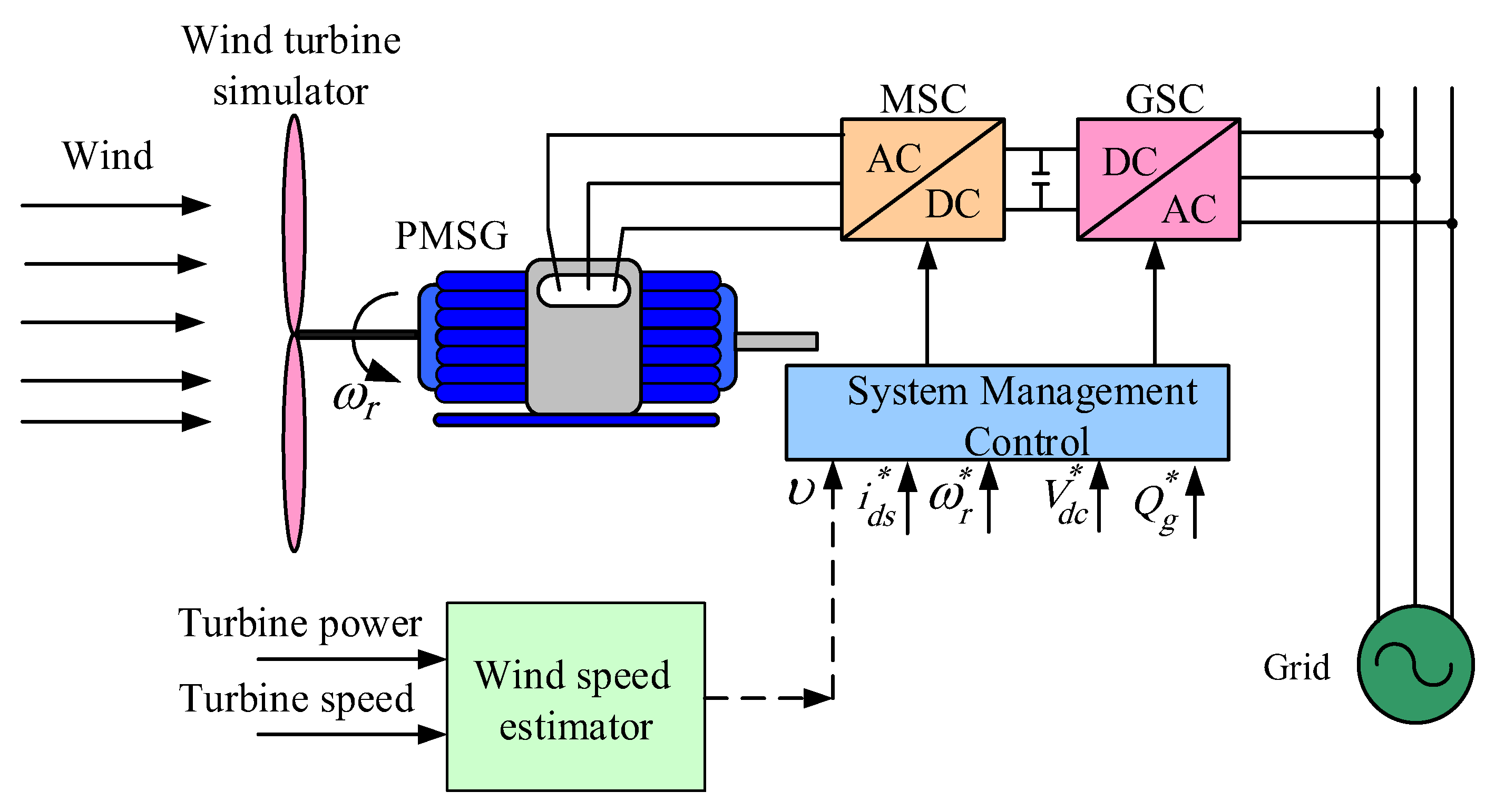
In grid-connected systems, as shown in
Figure 1, since a low switching frequency adversely affects the output current and power quality, it should substantially reduce the value of the total harmonics distortion (THD) during the modeling and design of the wind turbines [
19]. To mitigate such harmonics, the inductance of the input or output of the power conversion device has been used in the past. Still, when the generation system becomes large-capacity, a considerable inductance is required, which may be unacceptable from a practical implementation point of view. As a result, it is difficult to implement a filter due to the high cost of the filter and the poor performance in dynamic response. By adding the LCL part to the existing L filter, it is possible to effectively reduce harmonics in a system with a capacity of several hundred KVA. Since there is little change in the price of the entire system due to the addition of the filter, it is also effective in terms of cost [
20]. However, the unwise determination of the LC filters interconnected between the wind turbine and the electric utility may not permit any reduction possibility of THD of the output currents, which may cause severe instability and failure problems for the wind turbine integration with the electric utility. The inaccurate values of the LCL filter components also may cause the generation of more poles that can further negatively affect the integration of the wind turbine with the electric utility.
Moreover, the wind speed variation changes the speed of rotation, which will definitely change the frequency generated from the wind turbine. It can also change the placement of the harmonic components, which imposes a limitation on the LCL filter because it has limited or fixed bandwidth [
21]. Using the harmonic mitigation controller with the help of the proportional integrator can help overcome this problem and increase the bandwidth of the operation of the wind turbines [
22]. This method can suppress harmonic currents but cannot reduce the noise robustness of the system. Next, it is possible to use a proportional-resonant (PR) controller to remove the harmonic components of a specific frequency [
23,
24]. Still, it is important to have several PR controllers, equal to the number of harmonics that should be eliminated. There is a possibility that the system becomes unstable if the bandwidth is exceeded. A method of reducing the harmonic current of a specific frequency by redirecting the harmonic voltage has been proposed by [
17]. Still, there is a problem that a detection circuit is additionally required, and computation is complicated. Moreover, when the electrical utility voltage becomes unbalanced, the grid current also becomes unbalanced, which may cause resonance and oscillations at the point of integration of the wind turbine with the electric utility.
Another study was introduced in the literature using a sliding mode (SM) controller [
25] to reduce the DC-link voltage oscillations that substantially reduce the harmonic contents in the current and voltage. Based on the comparison study between the SM and PI controllers, the results showed improved performance with the use of the SM controllers in normal and abnormal operations [
25]. Unbalanced or distorted electric utility grid voltage generates abnormal grid currents. If the utility grid voltage is unbalanced, a ripple component equal to twice the utility grid frequency (120 Hz) occurs in the DC-link voltage. To remove the DC-link voltage ripple, a separation of the negative and positive components of the
dq-axis of the supply currents and each component should be controlled separately [
26,
27,
28].
The main contribution of this paper is the ability to extract the grid voltages and currents of positive, negative, 5th, and 7th-order components without affecting the components’ magnitudes or their phase delay. After separating these components, the positive and negative components of the grid-side currents are regulated by using PI-current controllers, which are tuned for each component separately. The proposed method eliminates the grid side’s unbalanced and distorted current components without needing to add hardware compared to the previous methods. Moreover, a detailed mathematical analysis for the PMSG and the back-to-back PWM converter is introduced in detail for reducing the 5th and 7th harmonics. The proposed system introduces a separate controller for each harmonic, and the active and reactive are controlled separately. The maximum power available from the wind turbine is also tracked. The results obtained from the simulation study coincide with the similar ones obtained from the experimental study in both normal and abnormal operating conditions. The outstanding results of harmonic reduction in the output current with a full separation of active and reactive power and the maximum power tracking control prove the superiority of the proposed wind turbine utility integration.
The proposed method’s novelty lies in its comprehensive and integrated approach, combining novel strategies for power extraction optimization, output current quality enhancement, and mitigation of grid voltage distortions. By addressing these key aspects, the method offers a unique and effective solution to improve the performance and stability of PMSG-based wind energy systems. The experimental validation and comparison with existing literature further demonstrate the novelty and superiority of the proposed method in fully remedying the effects of unbalanced grid voltages and achieving optimal power extraction.
Furthermore, the proposed method introduces robust controllers tailored for PMSG control. These controllers effectively compensate for specific output current components, such as the 2nd and 6th harmonic components, resulting in reduced dominant components in the output currents. By minimizing the impact of harmonic distortions, the method enhances the robustness and stability of the system, leading to higher power quality and improved overall performance.
Additionally, the method incorporates a current controller in the grid side converter, further mitigating the effects of unbalanced grid voltages. By compensating for specific output current components, such as the 2nd and 6th harmonic components, the method ensures the reduction of dominant harmonic contents, thereby improving the quality of the output current from the wind turbine.
The paper is organized into several sections to provide a comprehensive understanding of the research on permanent magnet synchronous generator (PMSG) control in wind energy systems. In
Section 2, the dynamics of wind turbines are discussed, covering the principles of wind energy conversion and power generation. This section establishes the foundation for understanding the behavior and characteristics of wind turbines. Moving forward,
Section 3 presents the mathematical model of the PMSG, including the equations and parameters used to represent the system. This model serves as the basis for the subsequent control strategy development.
Section 4 delves into the system control aspect, where a novel combination strategy is introduced. This strategy focuses on adapting the positive sequence of the
dq-axis output current to maximize power extraction while utilizing the negative sequence component to improve the quality of the output current. In
Section 5, the experimental results are presented. This section outlines the experimental setup and methodology used to validate the proposed control strategy and provides a detailed analysis of the obtained results under various operating conditions. Finally,
Section 6 concludes the paper by summarizing the main findings and contributions of the research, highlighting the superiority of the proposed strategy in addressing unbalanced grid voltages.
2. Wind Turbine Dynamics
All types of wind turbines work on the same principles regardless of their type or size, where they convert the kinetic energy stored in the wind into mechanical energy on the shaft of the electric generator. The market shows two main types of wind turbines: the horizontal axis and vertical axis wind turbines. Horizontal axis wind turbines are more widely used than vertical axis wind turbines due to their better performance, and the wide range of sizes where they can be designed from fractional kW size to several MW size, meanwhile vertical axis wind turbines have limited size due to some engineering problems [
29]. The relation between electric power generated and the wind speed can be obtained from Equation (1) [
30]:
where
ρ is the air density at the place where the turbine is installed,
R is the length of the turbine blades,
is the average linear wind speed,
β is the pitch angle, and
CP (
λ,
β) is the turbine power coefficient, a specific parameter for each generator dependent on the linear speed relationship between the rotational speed of the blades and the tip speed ratio (
λ). The power coefficient limit is established according to the Betz law at 59.3% in the case of horizontal axis turbines. Based on (1), it is possible to calculate the mechanical torque on the turbine axis as shown in (2) [
31]:
The power coefficient (
CP) is a parameter that converts the wind’s kinetic energy into mechanical rotational energy. Usually, this coefficient is determined from experimental curves for each turbine. A mathematical model has been developed to obtain a generalized form of the coefficient presented in (3) and (4) and a set of proposed values for the coefficients
C1 through
C6 [
32].
Figure 2 shows a typical set of
CP curves as a function of the linear speed ratio for different pitch angle values for a horizontal axis turbine [
23,
33,
34]:
In (2), it appears that the mechanical power on the turbine axis is directly proportional to
CP. In
Figure 2, it becomes evident that for certain pitch angle conditions (
β), only a single value of the linear velocity relation (
λ) guarantees the maximum value for
CP. Considering that the length of the blades is uniform and constant, the linear speed ratio is defined according to (5).
where
is the angular velocity of the propeller shaft.
3. Mathematical Model of PMSG
The choice of utilizing a permanent magnet synchronous generator (PMSG) in wind energy systems offers several advantages over other generator types such as squirrel cage induction generators (SCIG) and doubly fed induction generators (DFIG). Firstly, PMSGs have a higher power density compared to SCIGs and DFIGs, meaning that they can generate more power for a given size and weight. This is due to the absence of rotor windings in PMSGs, allowing for a more compact and lightweight design. Additionally, PMSGs have a higher efficiency since they eliminate the need for rotor power conversion and the associated losses present in DFIGs. PMSGs also provide a wider operating range, allowing for better performance in low wind speed conditions where other generator types may struggle. Furthermore, PMSGs exhibit superior grid compatibility as they are not reliant on slip rings or power electronics for control, resulting in reduced maintenance and increased system reliability. Overall, the advantages of using PMSGs in wind energy systems include higher power density, improved efficiency, wider operating range, and enhanced grid compatibility, making them a favorable choice over SCIGs and DFIGs.
The PMSG is made up of the following main elements: a rotor with permanent magnets and a stator with a three-phase or poly-phase winding. The rotor magnets form a constant magnetic field which is not possible to modify, unlike the traditional synchronous machine in which the amplitude of the rotor field is modified by modifying the value of the direct current. In the synchronous machine, it is considered that in the steady-state, the stator field and the rotor rotate at synchronous speed. In this way, the frequency and voltages of the generator are set. If the PMSG has
Np pole pairs, then the rotor’s rotation speed can be expressed by Equation (6):
ωr: Angular frequency in the rotor in (rad/s)
fe: Electric frequency of the stator in (Hz)
Np: Number of pole pairs.
Due to the high number of pole pairs in current machines, it is possible to eliminate speed multiplier boxes in this type of electrical machine. One of the advantages of this situation is that maintenance is reduced, mechanical losses of the gearbox are eliminated, and electrical losses in the rotor are eliminated because the excitation circuit of traditional synchronous machines is eliminated. On the other hand, there is a higher cost of the magnets and a loss of control over the amplitude of the rotor field.
The electromagnetic model of the PMSG for one of its phases is shown in
Figure 3 [
33]. The three-phase per phase equation that relates voltages to currents and magnetic fluxes for the PMSG is described in Equation (7) [
35]:
This expression makes it possible to obtain a model oriented in the same direction as the stator’s magnetic field vector. For this, the Park transformation is applied to the phase equations. This model in the
dq axes has the advantage of simplifying the control model since the voltages and currents in the
dq axes do not depend on the time in the steady-state condition. On the
dq axes the PMSG equations oriented with the rotor flux vector are shown in Equations (8) and (9) [
36]:
where
Lds and
Lqs are the synchronous reactance in direct and quadrature axes of the synchronous machine.
Furthermore, the concatenated fluxes as a function of the inductances and the flux created by the permanent magnets of the rotor
m, can be expressed as:
If the expressions of the magnetic flux are replaced in Equations (10) and (11), the following equations on
dq axes of the stator voltage can be obtained.
These equations can also be expressed in a simplified form as follows:
where
They are the direct and quadrature axes components of the electromotive force (emf) of the synchronous generator. From these expressions, the electromagnetic power can be defined, which is developed by the machine, as a function of the
dq components per rms phase, as shown in the following expression.
Replacing the components of the emf of the generator in
dq axes which are shown in Equation (18) with the values obtained from Equations (16) and (17), the electromagnetic power can be obtained from the following equation.
Since the torque is defined as
T =
P/
, then the expression for the PMSG electromagnetic torque in
dq axes is given by the following expression [
37]:
From the mechanical point of view, the PMSG is coupled to a rotational mechanical system (wind turbine) so that the mechanical system is modeled by the following expression.
where:
: Mechanical torque applied in (Nm)
: Coefficient of friction (Ns/rad)
: Total equivalent inertia of the turbine and generator in (Ns2/rad).
5. Experimental Results
The experimental validation of the proposed control system was conducted using a testbed setup, as illustrated in
Figure 8. The testbed consists of several key components, including the permanent magnet synchronous generator (PMSG), three-phase back-to-back converters, and an induction motor acting as a prime mover to emulate the mechanical power generated by wind turbines.
Table 2 provides an overview of the performance parameters of the PMSG used in the experimental setup. To facilitate the control and operation of the system, a PWM converter was constructed in the laboratory using SK40GB 123 SEMIKRON IGBT modules. These modules, along with a switch driver, were recommended for optimal performance. The experimental work employed a switching frequency of 10 kHz, with a sampling time of 0.6 ms.
The central control board plays a crucial role in the setup and includes a digital signal processor (DSP), signal conditioning, protection circuits, isolation circuits between the power converters, and control circuits. The DSP unit, specifically a TMS320F28335, facilitates communication between the DSP and various system peripherals such as the incremental encoder and digital-to-analog converter (DAC). The DAC enables data acquisition and interaction with an oscilloscope interface for communication with a computer.
The controllers employed in the experimental setup, including the DC-link voltage controller, grid-side converter (GSC) controller, motor-side converter (MSC) controller, and phase-locked loop (PLL) controller, are implemented on the DSP units. These controllers play essential roles in ensuring the stable operation and coordination of the system components.
The proposed testbed setup consists of a 3 kW PMSG coupled with a three-phase squirrel cage induction generator, which is further coupled with a motor drive. This configuration allows for precise control of the mechanical power transmitted to the PMSG, thereby emulating the variations inherent in wind turbines. The chosen setup size is suitable for experimental validation while representing the characteristics and performance requirements of practical wind energy systems.
Figure 9 presents the experimental results obtained when the wind speed varied within the range of 7 to 12 (m/s). The plot consists of three subplots, representing the wind speed, generator speed, and system power, respectively, from top to bottom. In
Figure 9a, we observe the changes in wind speed over time. As the wind speed fluctuates, the control system responds by adjusting the generator reference speed to maintain optimal performance. The control strategy employed in the experiment aims to track the maximum power point based on the optimal tip-speed ratio. Consequently, the generator reference speed is adapted accordingly, allowing the system to extract the maximum available power from the wind turbine.
To ensure efficient power extraction,
Figure 9b demonstrates how the generator reference speed closely follows the optimal tip-speed ratio as the wind speed varies. By dynamically adjusting the generator reference speed, the control system optimizes power production and maintains a high level of energy conversion efficiency.
Figure 9c provides insights into the behavior of the generator power in response to changes in wind and generator speeds. As the wind speed varies, the generator power exhibits a corresponding response, following the fluctuations in wind speed and generator speed. This relationship highlights the dynamic nature of the system, where the power output is continuously adjusted to match the prevailing wind conditions and ensure maximum power extraction from the wind turbine.
These experimental results depicted in
Figure 9 validate the effectiveness of the proposed control strategy. The ability of the system to adapt the generator reference speed based on the optimal tip-speed ratio allows for efficient power tracking and enhances the overall performance of the wind energy system. The close alignment between wind speed, generator speed, and system power demonstrates the successful integration of the control strategy, enabling optimal power extraction under varying wind conditions.
Figure 10 provides insights into the voltage and current distortions observed in the utility grid.
Figure 10a displays the distorted voltage waveform, highlighting the presence of harmonics and other irregularities. Similarly,
Figure 10b shows the distorted current waveform resulting from the unbalanced conditions of the utility grid voltage. These distortions in the voltage and current signals can significantly impact the performance and stability of the wind energy system.
Figure 10c illustrates the time variation of the DC-link voltage. The trace reveals notable variations in the DC-link voltage, which can exacerbate the harmonic contents of the output currents. This observation underscores the importance of controlling and stabilizing the DC-link voltage to mitigate harmonic distortions.
Moving on to
Figure 11, the distorted three-phase current waveforms are depicted. These distortions are primarily caused by the harmonic contents and unbalanced conditions of the utility grid voltage. The irregularities in the current waveforms further emphasize the challenges posed by unbalanced and distorted grid conditions.
Figure 12 showcases the grid side current components when using conventional current controllers.
Figure 12a presents the positive sequence components, while
Figure 12b depicts the negative current generated by the unbalanced voltage when transformed to the dq synchronous coordinate system. Notably, a ripple component with a frequency of twice the system frequency (120 Hz) is visible.
Figure 12c,d exhibits the grid d and q-axis currents corresponding to the 5th and 7th harmonic components. The current, converted to the dq synchronous coordinate system, reveals a pulsation component with a frequency six times that of the system frequency.
In contrast,
Figure 13 demonstrates the effect of the proposed compensation method on addressing the unbalanced and harmonic components. By tuning the proportional-integral (PI) controller gains effectively, the three-phase grid current waveforms become pure sinusoidal, reflecting the successful compensation for grid disturbances.
Figure 14 displays the
dq-axis current components, including positive, negative, and harmonic components, when the proposed controller is applied to mitigate the effects of unbalanced and distorted utility grid voltages.
Figure 14a presents the positive sequence current components, while
Figure 14b–d shows the reduction of negative sequence currents to zero, validating the effectiveness of the proposed compensation strategy.
Figure 15a–c showcases the continuously varying wind speed, voltage, and current waveforms when the compensation technique is applied in the presence of unbalanced and distorted grid voltage conditions. Notably, controlling the negative component of the grid current to a value close to zero reduces the ripple component in the current transformed to the synchronous coordinate system. The robustness of the proposed control strategy is evident from the negligible impact of speed variations on the grid current.
When applying the proposed method, the experimental results, the three-phase grid current is almost balanced despite the grid voltage imbalance and distortion. It is confirmed that the current grid control of the grid-connected PMSG wind turbine system significantly reduced the current negative sequence components and the harmonic components.
The selected novel combination strategy developed in this research paper to address the issue of unbalanced voltage in the utility grid when using a permanent magnet synchronous generator (PMSG) in wind energy systems has several notable effects and advantages compared to existing literature.
Maximized power extraction: The proposed strategy aims to maximize power extraction from the wind turbine. By adapting the positive sequence of the dq-axis output current, it ensures the efficient utilization of available power from the wind turbine. This effect is crucial in enhancing the overall performance and energy yield of the wind energy system.
Improved output current quality: Another effect of the novel strategy is the improvement in the quality of the output current. By utilizing the negative sequence component, the strategy helps mitigate the effects of unbalanced grid voltages, resulting in a more stable and higher quality output current. This improvement is vital in achieving grid compatibility and minimizing disturbances caused by unbalanced grid conditions.
Enhanced robustness: The proposed strategy introduces robust controllers specifically designed for PMSG control. These controllers compensate for the effects of specific output current components, such as the 2nd and 6th components. By reducing these dominant components in the output currents from wind turbines, the strategy enhances the robustness of the system and improves overall power quality.
Superiority over existing methods: In comparison with existing literature, the novel combination strategy stands out due to its ability to fully remedy the effects of unbalanced grid voltages. The detailed simulation and experimental studies conducted in this research demonstrate the effectiveness of the proposed strategy under various operating conditions. The obtained results showcase the superiority of the strategy in achieving power extraction optimization and high-quality output currents.
6. Conclusions
This paper presents a novel technique that effectively addresses the harmonic components and unbalance in utility grid currents. The harmonic content in the output current is primarily caused by distortions and unbalance in the electric utility voltages. To mitigate these issues, superior controllers are employed to remedy the effects of distorted and unbalanced utility grid voltages. Specifically, two controllers are utilized to reduce the 5th and 7th harmonic components in the utility grid currents. Additionally, a controller is introduced to separately regulate the reactive and active power flow from the proposed system.
Extensive simulations are conducted to validate the exceptional performance of the proposed controllers. Moreover, an experimental setup is implemented, utilizing a TMS320F28335 DSP, to further validate the simulation results. The results obtained from both the simulation and experimental studies exhibit a high degree of correlation, demonstrating the improved harmonic content in the electric utility currents and highlighting the superiority of the proposed controllers.
Comparisons are made with existing literature where alternative techniques were employed, as well as with the results obtained when the proposed control strategy was not utilized. These comparisons emphasize the substantially superior performance of the proposed converter. The main achievement of this study lies in the significant reduction of the 5th and 7th harmonic components in the electric utility currents, ultimately improving the quality of the power transmitted to the electrical utility grid, even when dealing with highly distorted voltages.
The successful reduction of harmonic content and improvement in power quality showcased in this study contribute to advancing the field of wind energy systems. The proposed technique holds promise for enhancing the integration of renewable energy sources, specifically permanent magnet synchronous generators (PMSGs), into utility grids by addressing issues of harmonic distortion and unbalance.
While the proposed method offers several advantages and has shown promising results, it is important to acknowledge certain limitations that may impact its utilization. These limitations include:
Complexity of implementation: Implementing the proposed method may require a sophisticated control system and specialized hardware. This could potentially increase the complexity and cost of the wind energy system.
Dependence on accurate system modeling: The effectiveness of the method relies on accurate modeling of the wind turbine system, including the PMSG and its associated components. Any inaccuracies or uncertainties in the system model could affect the performance of the method.


