Abstract
Achieving intelligent rock excavation is an important development direction in underground engineering construction. Currently, some rock-drilling jumbos are able to perform autonomous operations under ideal contour surfaces. However, irregular contour surfaces resulting from factors such as rock characteristics, drilling deviation, and blasting effects present a significant challenge for automated drilling under non-ideal surfaces, which constrains the intelligentization of rock excavation. To address this issue, this paper proposes a method for extracting contour surfaces and planning drilling paths based on a vehicle-mounted 3D scanner. This method effectively extracts contour surfaces and optimizes drilling paths, thereby improving work efficiency and safety. Specifically, the proposed method includes: (i) the real-time scanning of cross-sectional contours using a vehicle-mounted 3D scanner to construct an accurate three-dimensional point-cloud model and obtain contour over-digging information; the acquired data are compared with theoretical drilling maps in the vehicle’s coordinate system to re-plan the blasting-hole point set; (ii) the development of a volume-based dynamic search algorithm based on the irregularities of contour surfaces to detect potential collisions between holes; and (iii) the conversion of the drilling sequence planning based on the new blasting hole point set into a traveling salesman problem (TSP), and optimization using a Hybrid Greedy Genetic Algorithm (HGGA) to achieve path traversal of all drilling positions. The effectiveness of the proposed method was verified using rock excavation in a certain mine as an example. The results show that the overall recognition rate of the contour over-digging reached over 80%, the number of arm collisions was significantly reduced, and the distance traveled by the drilling rig was reduced by 35% using the improved genetic algorithm-based rock-drilling rig path planning.
1. Introduction
The development of unmanned mining [1] can promote mining technology to an intelligent level and enhance the core competitiveness of the mining industry. In the construction process of mines, the operation of a rock-drilling jumbo is one of the most important links. Currently, the operation of a rock-drilling jumbo mainly relies on manual completion, which has some disadvantages such as low operating efficiency. The operator needs to use multiple operating levers to move the drill bit to the drilling position on the rock surface, which requires visual completion and is prone to angle deviation, affecting the blasting effect and increasing the excavation cost [2]. Yuan et al. [3,4] proposed the research and development of intelligent, precision and rapid drilling technology and equipment, which needs further breakthroughs.
With the development of fully computerized rock-drilling-jumbo technology, the rock-drilling jumbos manufactured by mainstream manufacturers have already possessed autonomous operation functions under the ideal rock surface contour. However, due to the influence of factors such as rock characteristics, drilling deviation, and blasting effect, the irregularity of the rock surface contour after each cycle of blasting has become an important research topic for how to automatically drill holes on irregular contours. Wang [5] proposed an algorithm from the perspective of inverse kinematics to calculate the expected posture of the end of the boom, which is used to solve the problem of automatic drilling and compensate for pose errors to improve drilling accuracy. Kim et al. [6] proposed the use of a fully computerized automatic drilling system to improve the blasting effect of rock-drilling jumbos and reduce the total cycle time associated with the blasting process.
With the development of sensor technology, under complex geological conditions [7,8], the methods for measuring the contour of tunnel surfaces can be mainly divided into two categories: photogrammetry [9] and 3D-laser scanning [10,11,12]. The former method is severely affected by tunnel lighting, dust, and construction, etc. To further improve measurement accuracy and reliability, Yang et al. [13] proposed a fusion of vision systems and inertial navigation technology. The latter method is becoming increasingly popular in underground construction due to the acquisition of 3D point-cloud data of tunnel cross-sections. Zhang et al. proposed an automatic tunnel steel-arche extraction algorithm based on 3D LiDAR point cloud [14]. The proposed algorithm can effectively extract the edge points of steel arches from the 3D LiDAR point cloud of the tunnel without human assistance, achieving an accuracy of 92.1%. Cao et al. proposed a method for segmenting feature objects from 3D point-cloud data of subway tunnels to automatically detect damage and reconstruct the 3D model of the tunnel [15]. Xiang et al. proposed a method for detecting the flatness of tunnel surfaces based on point-cloud data [16]. The application of point-cloud data 3D reconstruction technology in shotcrete robots was discussed by Ouyang et al. [17]. They proposed a method based on point-cloud stitching and normal reorientation to achieve the 3D reconstruction of the tunnel contour, which lays the foundation for further research on wet-shotcrete trajectory planning, state monitoring, and control strategies, but no substantive research has been conducted on wet-shotcrete path planning.
There is a few studies on arm track control and monitoring in the field of fully automated rock-drilling trolley construction. The theoretical rock drilling working face is shown in Figure 1a, but the actual working face is shown in Figure 1b, with uneven contours on the working face and irregular working spaces caused by over-digging of the peripheral profile. Conventional methods may require setting the maximum retraction plane of the advancing beam through a computer before each cycle, resulting in low planning efficiency and unsatisfactory solutions in order to achieve collision-free path trajectories [18,19].
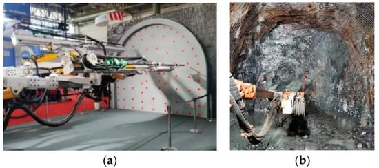
Figure 1.
Drilling diagram of rock-drilling jumbo. (a) Virtual face; and (b) actual working face.
Our paper proposes a method for extracting the working face space and path planning based on onboard 3D scanning. By effectively extracting the contour of the working face, optimizing the drilling path, reducing human intervention, and improving work efficiency and safety, the following contributions are made: (i) obtaining the contour point-cloud data of the working face through onboard scanning, using the dynamic volume search method [20] to extract and identify obstacles, and optimizing the local arm movement path between drilling holes to avoid collision between the arm and the uneven contours of the working face and the under-digging profile of the periphery; (ii) simplifying the process of traversing each section hole of the rock drilling trolley into a TSP [21] problem, solving the rock drilling trolley’s path-planning problem through a hybrid greedy genetic algorithm [22,23,24], and obtaining an approximate optimal path.
The organization of this paper is as follows. Section 2 discusses the composition and control methods of automatic drilling paths, with Section 2.1 introducing the composition of automatic drilling paths and Section 2.2 introducing the control plan for automatic drilling paths. Section 3 introduces collision-free local path planning, with Section 3.1 introducing the positioning and contour acquisition of the rock drilling trolley, Section 3.2 introducing the collision detection of the rock drilling arm, and Section 3.3 introducing the local path solution. Section 4 introduces the theory of global path planning, with Section 4.1 introducing the algorithm design theory, Section 4.2 introducing the global drilling path of the rock drilling trolley based on the HGGA algorithm, and Section 4.3 introducing the simulation and results of the drill-rod path planning. Section 5 introduces specific applications, and the conclusion of the research is given at the end of the paper.
2. Automatic Drilling Path Composition and Control
2.1. Automatic Drilling Path Composition
The automatic drilling process of the full-computer rock-drilling jumbo is to drill and control each drilling point on the working face according to the set coordinates. The path planning determines the construction efficiency after determining the coordinates of the drilling point. If the drilling path planning is unreasonable, it will even cause a collision between the propulsion beam and the tunnel face, failing the drilling work. The purpose of path optimization is to shorten the running path as much as possible, and the arm frame is drilled in sequence according to the shortest path without collision, thus greatly improving the detection efficiency. The trajectory between the two holes is shown in Figure 2.
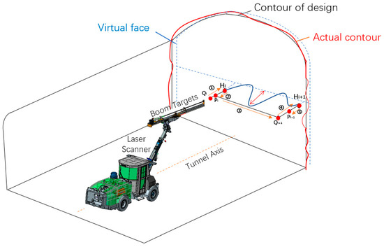
Figure 2.
Drilling path diagram.
Figure 2 shows that the drilling process can be decomposed into three processes: reaching the positioning point Q, approaching the drilling point H, and returning to the retreat point P. The drilling arm quickly reaches the first positioning point Q, and approaches the actual drilling point from the normal direction of entry point H. After the drilling is completed, it quickly retreats to point P along the HP direction with a retreat speed. Now that the drilling of the current hole is completed, then the drill arm quickly moves to the positioning point Q of the next drilling point, repeats the previous steps, and finally completes the drilling of all holes.
The whole movement path of the arm frame is mainly composed of ①, ②, and ③:① segment is the advancing distance of the propulsion beam in the direction of the drilling after the propulsion beam reaches the positioning point; ② segment is the retreat distance of the propulsion beam after the drilling is completed; and ③ segment is the distance from the current retreat point to the next drilling positioning point. The total movement distance of the propulsion beam is represented by the following equation.
where t is the sum of the advancing distance ① and the retreating distance ② of the propulsion beam; and l is the sum of the distance from the retreat point to the positioning point ③.
where is the distance from the positioning point to the drilling point; is the retreat distance after drilling a point; n is the total number of drilling points; and is the distance from the first borehole positioning point to the borehole positioning point. . So, Equation (1) can be rewritten as the following Equation.
Therefore, the above path optimization problem is transformed into two aspects:
(i) For the distance between ① and ② segments, a 3D scanner system is installed on the full-computer rock-drilling jumbo because of the unevenness of the tunnel face, and the concave and convex conditions of the tunnel face are obtained by the scanner, thus the retreat distance is automatically calculated to ensure that local collisions are avoided during operation.
(ii) The optimization of ③ segment distance is transformed into a path optimization problem of a 2D plane. The optimization of the drilling path is transformed into the objective function of distance optimization:
with:
where is the coordinate value of the drilling point i, and is the coordinate value of the drilling point. The optimal solution of the optimization function is the minimum value of l.
Therefore, the measurement path planning can be understood as follows: there are n points in the space where the distance between each two points is known. The propulsion beam starts from a certain point and traverses each point in space. The limit of the path is that each point can only be reached once. Obviously, the drilling point path optimization problem is a typical traveling salesman problem.
2.2. Drilling Path Control
In this paper, the rock-drilling jumbo is used for positioning. The vehicle-mounted laser radar scanner scans the section to generate point-cloud data and performs 3D modeling. Through the design of the borehole map, the section of the drilling point position, drilling depth, and other data are generated. The automatic drilling process of the rock-drilling jumbo is shown in Figure 3.
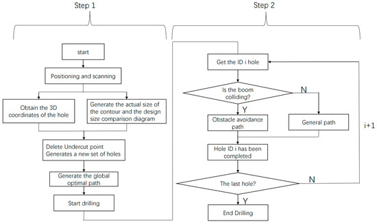
Figure 3.
Flowchart of the section drilling.
Step 1: Global optimal path:
- (a)
- After the jumbo is positioned, the actual over-under-excavation data is obtained by intercepting the 3D-scanner data in the working area. Meanwhile, combined with the designed borehole map, the actual over-under-excavation situation is compare with the designed borehole map to obtain a comparison diagram of the actual contour and the design contour as shown in Figure 4a.
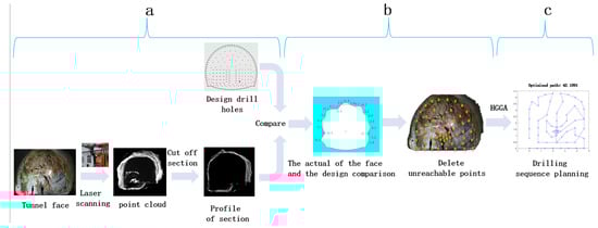 Figure 4. Global optimal path-planning diagram.
 - (b)
- Some points that cannot be reached because the tunnel is under-excavated are removed, and a new set of borehole maps are generated, as shown in Figure 4b.
- (c)
- Converting the drilling sequence of jumbo from a newly generated borehole collection into a TSP problem, and path planning for the newly generated borehole map set to obtain a better hole-drilling path planning is obtained through the HGGA algorithm, as shown in Figure 4c.
Step2: Collision-free local path planning
Concave and convex information of the tunnel face is extracted in real-time by obtaining point-cloud data, and using dynamic volume search (DSV) to monitor collisions on the current path and optimize the ➀→➁→➂→➃→➄ path, as shown in Figure 5. The specific implementation process is introduced in Part 3.
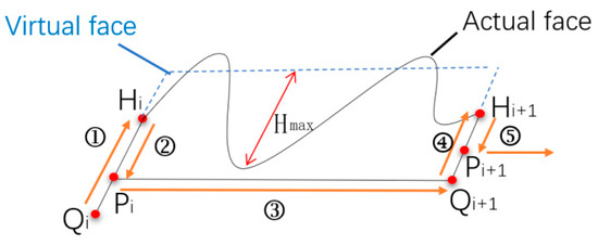
Figure 5.
Collision-free local path.
3. Collision-Free Local Path Planning
3.1. Positioning and Contour Acquisition of Rock-Drilling Jumbo
Figure 6 shows that the jumbo is positioned with the point scanner; when P1 and P2 points are known points, the coordinates of the jumbo and the scanner are determined by the rear intersection method.
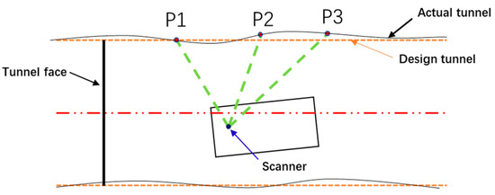
Figure 6.
Jumbo positioning and contour scanning.
After the positioning is completed, we used the LMS511 scanner provided by the German SICK company (Düsseldorf, Germany), which is driven by a servo motor, as shown in Figure 7.
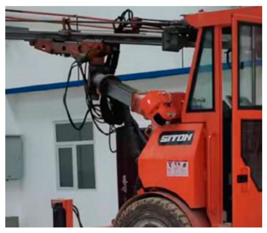
Figure 7.
Vehicle-mounted 3D scanner.
The scanner scans the tunnel face contour; the scan results are shown in Figure 8.
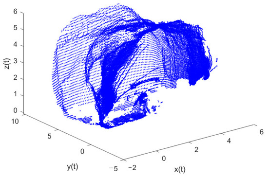
Figure 8.
Contour scanning of tunnel face.
3.2. Collision Detection of Rock-Drilling-Arm Frame
In the process of rock drilling, the propulsion beam may collide with the surrounding products of the tunnel face contour, resulting in equipment damage. Therefore, collision detection and automatic obstacle avoidance become more important. The boundary box method is one of the most common methods in collision detection; however, the boundary box method is suitable for the detection of simple solid structures, such as cylinders, rectangles, and other obstacles. When used for this free-form surface detection [25] of the tunnel face, the effect is not ideal. So, this section uses a new dynamic volume search (DSV) method to automatically avoid interference.
As shown in Figure 9, when the end of the propulsion beam moves from point to point , a point to point path is formed. According to the coordinates of point and point , the 3D-space linear equation is obtained as follows:
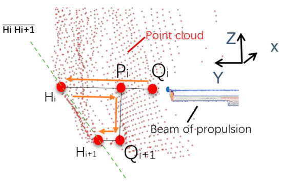
Figure 9.
Arm frame collision detection.
In order to detect collisions during the movement of the propulsion beam, a volume area is constructed for point-cloud search:
where is the width of the propulsion beam to avoid interference distance, is the length of the propulsion beam (four to five meters), and n is the number of holes to be drilled. All points in a point-cloud search are represented by a set R:
where n is the number of point sets in the current search region, is the distance from point to line , and the following equation is obtained:
I = 1, n − 1
If the sign function is 1, it means that there is no collision point when moving from point to point ; otherwise, there is a collision point in the path. is the set threshold, which ranges from 3 to 5 cm.
3.3. Local Path Solving
During the drilling arm movement, when the drilling point moves from the point to the point .
- (a)
- When the point boom collision detection Sign = 1, which means no collision occurs in the path, as long as the propulsion beam retreats for a certain safe distance, there is no collision. The safe distance from point H to point P is usually 5–10 cm, and the optimized path is →→→→, as shown in Figure 10.
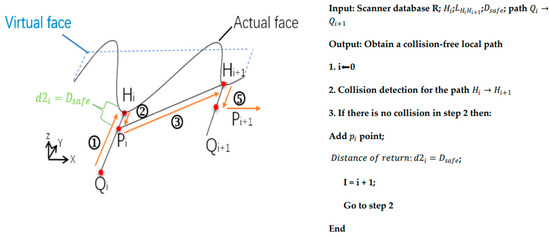 Figure 10. Collision-free path.
 - (b)
- When the boom collision detection Sign = 0, which means there is a collision in the path, through the dynamic volume search method, the point coordinate with the smallest value y in set R is obtained as , and the propulsion beam needs to retreat by distance to ensure there is no collision. The value of is shown in Equation (13). The optimized path is →→→→→, as shown in Figure 11.
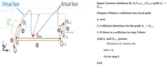 Figure 11. Collision path generation- Automatic drilling.
- (c)
- There is a problem of under-excavation interference around the excavation contour because of uneven blasting, which results in a long retreat distance, and usually . Therefore, the drilling hole depth cannot meet the design footage requirements, or the arm frame and the surrounding rock under-excavation interference problem, so the drilling path should remove the point, and continue automatic drilling the next point after from automatic mode to manual mode. Where is calculated based on drilling depth: , where the drill rod length is , and the single-cycle drilling depth is , which is too large and leads to an insufficient current drilling depth, as shown in Figure 12.
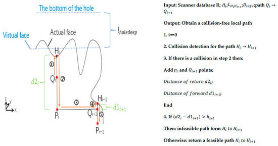 Figure 12. Collision path generation- manual drilling.
4. Analysis of the Global Path Planning Algorithm
4.1. Algorithm Design and Process
The drilling process of the rock-drilling jumbo is to traverse all the holes to be drilled through a certain sequence once and only once. The traversal process of the hole position is similar to the solution of the traveling salesman problem, and the drilling sequence of the single-arm rock-drilling jumbo can be transformed into a traveling salesman (TSP) problem for a solution.
Assuming that there are n points to be drilled, there are (n − 1)! possibilities for the total sort. It is a typical NP problem because of the large number of holes and many sorting methods. The cost of finding the optimal solution by listing all solutions is very high. Aiming at such a problem, intelligent algorithms are generally used to find a better solution with less computation as a better drilling sequence, and this method usually outperforms the classical method. In our paper, the initial population is optimized by the greedy algorithm, and the genetic algorithm improved by the greedy operator, which is used to improve the evolution speed of the population.
The genetic algorithm creates some new genes by crossover and mutation; these genes will enter the next round of competition. The genes are judged by the fitness function: the high-fitness individuals are regarded as more suitable for survival, and the low-fitness individuals are eliminated by nature as defective individuals. In order to ensure the diversity of species, a certain number of genes need to be retained as the gene pool of the next generation of individuals in the individuals with lower-fitness function. The algorithm flow is shown in Figure 13.
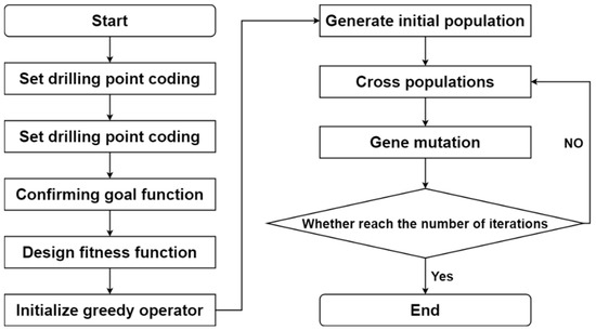
Figure 13.
Flowchart of the evolution process.
4.2. Drilling Path Planning of Rock-Drilling Jumbo Based on HGGA Algorithm under Constraints
4.2.1. Hole Coding
The main purpose of coding is to convert practical problems into processes that can be solved mathematically. In this paper, the position of section points are arranged in sequence by X-axis and Z-axis, and the position of section points that need to be drilled are marked. The to-be-drilled hole position number and coordinates of the section are obtained. The unit of coordinates is meters. The direction of the mileage vector is regarded as the Y-axis, and the coordinates of the Y-axis of the virtual tunnel face are considered to be zero. Assuming that the total number of holes in a section is sixty-two, according to the construction technology requirements of the rock-drilling jumbo, the eight holes at the bottom need to be drilled first, then the path can be determined. Therefore, the parameters of these eight holes are removed from the section coordinate table and the remaining hole positions need the rock-drilling jumbo to drill, as shown in Figure 14.
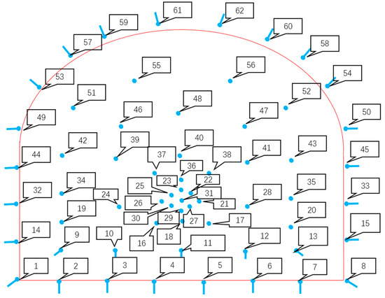
Figure 14.
Section coordinate system establishment and coding.
According to the process requirements, one to eight holes are needed to complete the drilling work first. The drilling sequence of one to eight holes should be 1-2-3-4-5-6-7-8 or 8-7-6-5-4-3-2-1, the order of which is obtained by the empirical method. In this paper, the former was selected as the drilling sequence. The coordinate points of fifty-four holes in nine to sixty-two holes were numbered and recorded as , , …, .
4.2.2. Confirming Goal Function and Fitness Function
The goal function is to evaluate the overall path length. The drilling path of the rock-drilling jumbo begins in situ, moving from the first hole to the last hole, and then back to the safe position. The total path is:
Assuming that there are N individuals in each generation, there will be a total of K evolutions. For the kth generation of individuals, it can be expressed as follows.
where .
In order to increase the discrimination of the fitness function, in the k-generation individuals, , the fitness function can be designed as follows:
The probability of the individual j in the kth generation being selected in the present age is
4.2.3. Initialize Greedy Operator and Generate Initial Population
In order to optimize the population, the distance between all two points is calculated and arranged according to the length of the distance. The distance between the two drill points A and B is the same as the distance between B and A, which has less impact on the population, so the latter is removed. Ten combinations with the shortest distance can be obtained as greedy operators. Based on this, the initial population is generated, and ten groups of shortest-distance operators can be obtained, as shown in Table 1.

Table 1.
Shortest 10 groups of data.
Here, we use the joining of ten greedy operators as an example. Assuming that the initial population is five-hundred, in order to add the greedy operators to the population initialization, in the process of initializing the population, the shortest point is removed from the corresponding sequence, and only other numbers are initialized. For example, the individuals of a population are
where the first individual, c1 = 26, c2 = 21; the second individual, c1 = 31, c2 = 26; the third individual, c1 = 23, c2 = 21; take ten individuals as a cycle, and so on. The remaining drilling numbers of individual are randomly generated to obtain the initial population.
4.2.4. Cross-Population and Variation
The generated N individuals are crossed, and the parts between the individuals c4 and c7 are crossed. At the same time, the crossed individuals are compared with the original individual to preferential select the next-generation individuals.
The fitness of , , , are calculated, then the two individuals with lowest fitness are removed and the better two individuals kept.
In our paper, the method of uniform mutation is adopted. In the interval of [1, 59], two mutually exclusive integers and are randomly generated to exchange the positions of individual and . For example, randomly generate = 4, = 9.
The individual after mutation is
4.2.5. Judgment and Iteration
The function is then judged to determine whether the fitness value meets the requirements and whether the number of iterations meets the operation preset. If the requirements are met, the calculation is stopped. Additionally, if the requirements are not met, the above process is repeated.
4.3. Simulation and Results of Drill Rod Path Planning
4.3.1. Empirical Method
The single-arm rock-drilling jumbo needs to drill many times in the section of each tunnel. Taking the section of a mine as an example, with a section height of 4.3 m and a width of 4.6 m. The traditional trajectory movement method is basically realized through experience: experienced workers will control the jumbo to drill along the hole position of the outer contour in the section, and then drill in the middle of the hole, as shown in Figure 15. After calculation, the total length of the trajectory of the jumbo is 64.3485 m.
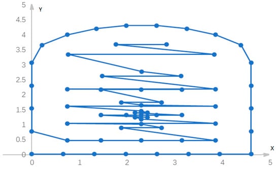
Figure 15.
Empirical trajectory planning.
4.3.2. Hybrid Greedy Genetic Algorithm
The optimal solution can be obtained when the population size is 500 and the number of iterations is 3000, as shown in the following figure. When the shortest first 5 and first 10 distances are processed, the evolutionary rate of the algorithm with the greedy operator is significantly faster than that of the conventional genetic algorithm, and the higher the number of operators, the faster the evolution. The shortest-distance optimization results are shown in Figure 16 and the fitness evolution curve is shown in Figure 17.
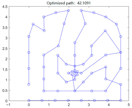
Figure 16.
Optimal path result.
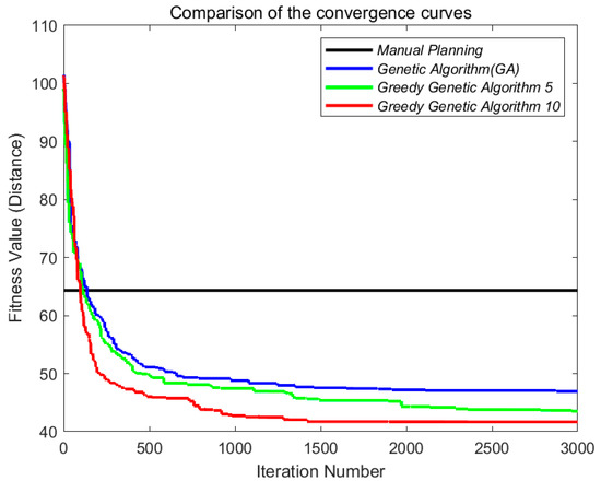
Figure 17.
Fitness evolution curve.
Based on the comparison in Table 2, it can be seen that the path generated by the traditional empirical method is longer (64.3 m), so a relatively short drilling path can be found by the genetic algorithm.
Table 2.
Comparison of conclusions of different algorithms.
After adding ten greedy operators to improve the genetic algorithm, the optimal distance can be shortened by about 35%, and the solution time is also greatly improved.
5. Field Results and Analysis
Taking the tunnel excavation of a mine in Zijin Mining Shanxi Branch as an example, with a section height of 4.7 m and a width of 5 m. The Z3C fully computerized rock-drilling jumbo produced by Jiangxi Xintong Machinery Manufacturing Co., Ltd. (Pingxiang, China) was used, and the excavation was 3.7 m per cycle.
The specific implementation process is shown in Figure 18, which is divided into four steps:
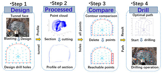
Figure 18.
Generation process of drilling path.
- (1)
- According to the contour size of the excavation section, the blasting plan was designed, and imported into the control system of the jumbo.
- (2)
- The vehicle-mounted scanner was used to obtain the three-dimensional point-cloud image of the driving direction, and the three-dimensional data was sectioned by point cloud to obtain the minimum contour size of the roadway.
- (3)
- The actual contour was compared with the theoretical contour to obtain the overcut state around the contour, and the possible collision points during the boom movement were deleted to form a new set of points to be drilled, as shown in Figure 19.
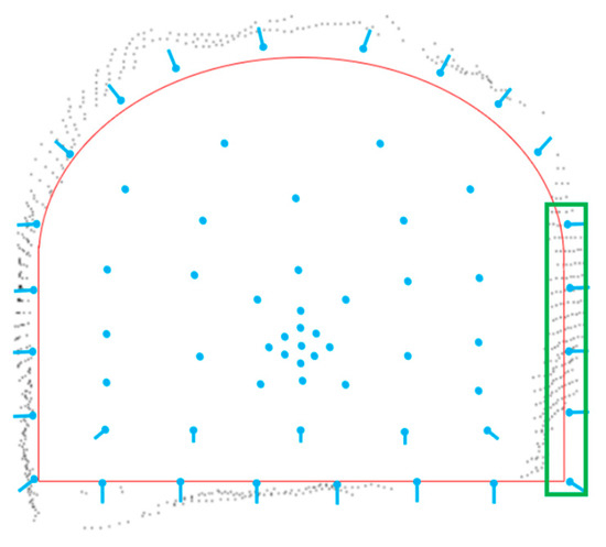 Figure 19. Generation of set points to be drilled. The hole int the green square are the possible collision points.
 - (4)
- The newly generated points to be drilled were set, and the optimal path was obtained using the greed-genetic algorithm, as shown in Figure 20. The layout after automatic planning by the control system of the drilling rig is shown in Figure 21, where the green mark represents the starting point, and the red mark represents the end point of drilling. After the drilling path planning was completed, automatic drilling control could be started with one key. The drilling process and effect are shown in Figure 22.
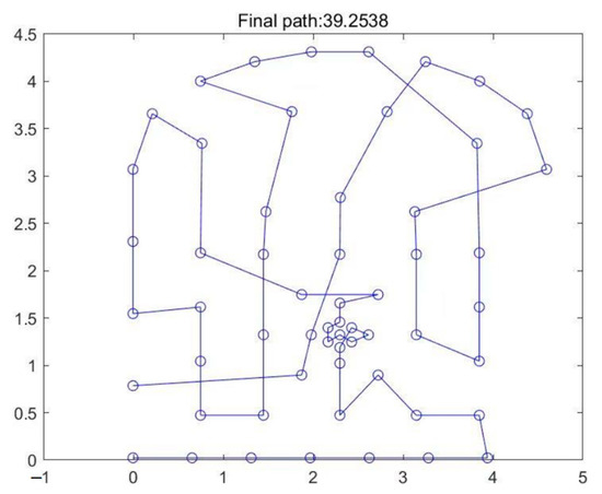 Figure 20. Optimal path hole diagram.
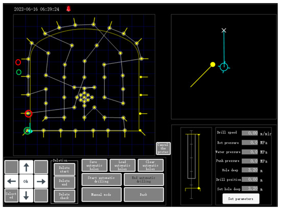 Figure 21. Computer-generated blasting hole map on board.
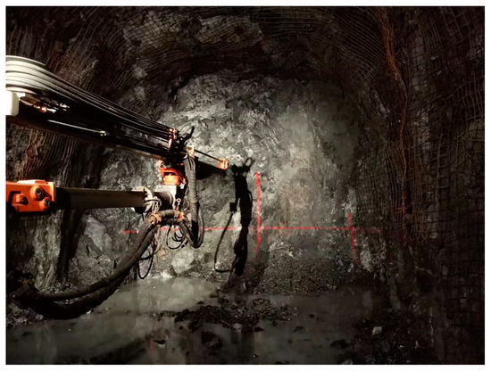 Figure 22. The drilling process and effect.
Jumbo counts eight cycles of data with 62 boreholes and 24 perimeter boreholes per cycle; Table 3 is the analysis table of the drilling results. One of the collisions was caused when the scanner failed to recognize the anchor net.
Table 3.
Effect analysis of eight-cycled peripheral hole drilling.
From the analysis of the statistics in the table, it can be seen that the project achieved high-precision scanning of the cross-section contour using an onboard scanner, further extracting the minimum contour of the surrounding area compared with the actual cross-section, generating a predicted collision point set, deleting the collision point set, and generating a new point set. Finally, the Hybrid Greedy Genetic Algorithm (HGGA) algorithm was used to generate the optimal path.
At the same time, due to the unevenness of the surrounding area of the mine, the interference during automatic operation of the rock drilling trolley mainly occured on the underexcavated contour and uneven face of the surrounding area. By processing the scanning data, the underexcavated recognition rate was high, with an average value of over 80%, avoiding the occurrence of interference between the arm frame and the contour. The reason for the collision is that the steel bar anchor mesh of the anchor mesh trolley is not installed as required and cannot be fully recognized.
The anti-collision effect of local paths on uneven working surfaces was good, and no collisions occurred. According to on-site statistics, as shown in Table 4, more than 83% of them needed to retreat a certain distance to avoid collisions, while a few only needed to retreat a certain safe distance to avoid collisions. Very few needed to delete points due to the large distance of retreat and manually handled them.
Table 4.
Local anti-collision path statistics results.
In summary, during the whole-brain automatic rock drilling process, the contour was obtained through a 3D scanner, and a global path optimization and local path collision prevention program were added. The arm frame can effectively avoid interference problems caused by the underexcavation of the cross-section contour, and the collision prevention effect is good.
6. Conclusions
- (1)
- Vehicle-mounted 3D-scanning technology has the advantages of a high recognition degree of overcut and undercut, and the recognition rate of the scanner to the surrounding interference objects reached more than 80%, which effectively reduces the interference probability between the arm and the palm face contour.
- (2)
- Drilling path-planning methods include global optimal path and local anti-collision path solutions. The global path uses the accurate three-dimensional point-cloud model to obtain contour overcut and undercut information. The point-cloud data in the vehicle body coordinate system and the theoretical hole layout map are compared and analyzed, and the hole point set is replanned. According to the new hole point set, the hole sequence planning is converted into the traveling salesman problem (TSP), which is optimized by hybrid greedy genetic algorithm (HGGA). To realize the traversal path of all holes, one must effectively shorten the drilling path, improve the working efficiency, and reduce the total distance of movement by 35%. Aiming at the uneven information of the palm surface, a dynamic search algorithm based on volume was developed to detect the potential collision of the local path between holes. It was discussed in three cases, including non-collision path, collision path and too-long-backtracking distance. The effectiveness and advanced nature of the method were verified on site.
- (3)
- This method based on contour recognition and optimal path planning of drill rods proposed in this paper puts forward a solution for promoting fully automatic drilling construction.
Author Contributions
Y.L. and P.P. participated in data analysis, participated in the design of the study and drafted the manuscript, and carried out the statistical analyses; H.L., J.X. (Jinghua Xie), L.L. and J.X. (Jing Xiao) collected field data and helped to draft the manuscript. All authors have read and agreed to the published version of the manuscript.
Funding
This work was supported by the National Key Research and Development Program of China under grant 2022YFC2904105, the Natural Science Foundation of Hunan Province (No. 2022JJ30699, No. 2023JJ10064), and the Science and Technology Innovation Program of Hunan Province (No. 2021RC4055, No. 2022RC1182).
Institutional Review Board Statement
Not applicable.
Informed Consent Statement
Not applicable.
Data Availability Statement
Not applicable.
Conflicts of Interest
The authors declare no conflict of interest.
References
- Li, J.; Zhan, K. Intelligent mining technology for an underground metal mine based on unmanned equipment. Engineering 2018, 4, 381–391. [Google Scholar] [CrossRef]
- Jiang, Q.; Ahmed, S.N. The Kinematics of 6R-2P Mining Drill Jumbo. J. Mech. Robot. 2014, 6, 034501. [Google Scholar] [CrossRef]
- Yuan, S.; Sun, B.; Han, G.; Duan, W.; Wang, Z. Application and Prospect of Curtain Grouting Technology in Mine Water Safety Management in China: A Review. Water 2022, 14, 4093. [Google Scholar] [CrossRef]
- Yuan, S.; Han, G. Combined Drilling Methods to Install Grout Curtains in a Deep Underground Mine: A Case Study in Southwest China. Mine Water Environ. 2020, 39, 902–909. [Google Scholar] [CrossRef]
- Wang, Y.; Fang, C.; Jiang, Q.; Ahmed, S.N. The automatic drilling system of 6R-2P mining drill jumbos. Adv. Mech. Eng. 2015, 7, 504861. [Google Scholar] [CrossRef]
- Kim, S.J.; Kim, J.G.; Ko, Y.H.; Ahn, J.M.; Kim, N.S.; Yang, H.S. Advancement of Blast Effect by Inducing Drill Jumbo on Automatic Drilling System. Explos. Blasting 2016, 34, 10–17. [Google Scholar]
- Wu, S.; Zhang, Z.R.; Chen, J.H.; Yao, Y.; Li, D.Q. Characterisation of stress corrosion durability and time-dependent performance of cable bolts in underground mine environments. Eng. Fail. Anal. 2023, 150, 107292. [Google Scholar] [CrossRef]
- Wu, S.; Hao, W.Q.; Yao, Y.; Li, D.Q. Investigation into durability degradation and fracture of cable bolts through laboratorial tests and hydrogeochemical modelling in underground conditions. Tunn. Undergr. Space Technol. 2023, 138, 105198. [Google Scholar] [CrossRef]
- Zhu, D.; Ji, K.; Wu, D.; Liu, S. A Coupled Visual and Inertial Measurement Units Method for Locating and Mapping in Coal Mine Tunnel. Sensors 2022, 22, 7437. [Google Scholar] [CrossRef]
- Wróblewski, A.; Wodecki, J.; Trybała, P.; Zimroz, R. A Method for Large Underground Structures Geometry Evaluation Based on Multivariate Parameterization and Multidimensional Analysis of Point Cloud Data. Energies 2022, 15, 6302. [Google Scholar] [CrossRef]
- Janus, J.; Ostrogórski, P. Underground Mine Tunnel Modelling Using Laser Scan Data in Relation to Manual Geometry Measurements. Energies 2022, 15, 2537. [Google Scholar] [CrossRef]
- Jia, D.; Zhang, W.; Liu, Y. Systematic approach for tunnel deformation monitoring with terrestrial laser scanning. Remote Sens. 2021, 13, 3519. [Google Scholar] [CrossRef]
- Yang, W.; Zhang, X.; Ma, H.; Zhang, G. Laser Beams-Based Localization Methods for Boom-Type Roadheader Using Underground Camera Non-Uniform Blur Model. IEEE Access 2020, 8, 190327–190341. [Google Scholar] [CrossRef]
- Zhang, W.; Qiu, W.; Song, D.; Xie, B. Automatic tunnel steel arches extraction algorithm based on 3D LiDAR point cloud. Sensors 2019, 19, 3972. [Google Scholar] [CrossRef]
- Cao, G.P.; Liu, X.S.; Liu, N. Segmentation of subway tunnel wall surface objects based on laser 3D point cloud. Acta Opt. Sin. 2020, 40, 2110001. [Google Scholar]
- Xiang, L.; Ding, Y.; Wei, Z.; Zhang, H.; Li, Z. Research on the Detection Method of Tunnel Surface Flatness Based on Point Cloud Data. Symmetry 2021, 13, 2239. [Google Scholar] [CrossRef]
- Ouyang, Q.; Lin, Y.; Zhang, X.; Fan, Y.; Yang, W.; Huang, T. Application of 3D reconstruction technology based on an improved MC algorithm in a shotcreting robot. Appl. Opt. 2022, 61, 8649–8656. [Google Scholar] [CrossRef] [PubMed]
- Becker, M.; Hansen, S.; Wesarg, S.; Sakas, G. Path Planning for Multi-port Lateral Skull Base Surgery Based on First Clinical Experiences. In Clinical Image-Based Procedures. Translational Research in Medical Imaging. CLIP 2013. Lecture Notes in Computer Science; Springer: Cham, Switzerland, 2014; Volume 8361. [Google Scholar]
- Kim, D.H.; Hoang, G.; Bae, M.J.; Kim, J.W.; Yoon, S.M.; Yeo, T.K.; Kim, S.B. Path tracking control coverage of a mining robot based on exhaustive path planning with exact cell decomposition. In Proceedings of the 2014 14th International Conference on Control, Automation and Systems (ICCAS 2014), Gyeonggi-do, Republic of Korea, 22–25 October 2014; pp. 730–735. [Google Scholar]
- Liu, Y.; Zhao, W.; Sun, R.; Yue, X. Optimal path planning for automated dimensional inspection of free-form surfaces. J. Manuf. Syst. 2020, 56, 84–92. [Google Scholar] [CrossRef]
- Abbas, A.T.; Aly, M.F.; Hamza, K. Optimum drilling path planning for a rectangular matrix of holes using ant colony optimization. Int. J. Prod. Res. 2011, 49, 5877–5891. [Google Scholar] [CrossRef]
- Albalawneh, D.A.; Afendee Mohamed, M. Evaluation of Using Genetic Algorithm and ArcGIS for Determining the Optimal-Time Path in the Optimization of Vehicle Routing Applications. Math. Probl. Eng. 2022, 2022, 7769951. [Google Scholar] [CrossRef]
- Tsagaris, A.; Mansour, G. Path planning optimization for mechatronic systems with the use of genetic algorithm and ant colony. IOP Conf. Ser. Mater. Sci. Eng. 2019, 564, 012051. [Google Scholar] [CrossRef]
- Zhang, Z.; Lu, R.; Zhao, M.; Luan, S.; Bu, M. Robot path planning based on genetic algorithm with hybrid initialization method. J. Intell. Fuzzy Syst. 2022, 42, 2041–2056. [Google Scholar] [CrossRef]
- Zhang, G.; Sha, J.; Wang, X.; Lv, Y.; Zhao, H.; Yan, Z. A Robot Spraying Path Planning Method for the Digital Camouflage Pattern. In Proceedings of the 2020 Chinese Automation Congress (CAC), Shanghai, China, 6–8 November 2020; IEEE: Piscataway, NJ, USA, 2020; pp. 3470–3475. [Google Scholar]


Disclaimer/Publisher’s Note: The statements, opinions and data contained in all publications are solely those of the individual author(s) and contributor(s) and not of MDPI and/or the editor(s). MDPI and/or the editor(s) disclaim responsibility for any injury to people or property resulting from any ideas, methods, instructions or products referred to in the content. |
© 2023 by the authors. Licensee MDPI, Basel, Switzerland. This article is an open access article distributed under the terms and conditions of the Creative Commons Attribution (CC BY) license (https://creativecommons.org/licenses/by/4.0/).