Abstract
The long-term stability of underground energy reserves is closely linked to salt rock creep. To study the creep behavior of salt rock, creep tests were conducted on salt rock specimens under various confining pressures and axial stresses. The test results reveal that the creep of salt rock is influenced by the combined effect of confining pressure and deviatoric stress, which represents the difference between axial and confining pressure. Subsequently, a long-term strength and time-controlled viscoplastic damage body is proposed by considering the plastic deformation in the steady-state creep stage. The viscoplastic damage body is connected in series with the fractional-order Maxwell model to form a new six-element nonlinear creep model generalized to three-dimensional form. The applicability of the new model was verified using triaxial creep test data of salt rock, and it was found to describe the creep curve more accurately compared to the Nishihara model. A sensitivity analysis of the model parameters indicates that different parameters affect various creep stages, and creep curves under different loads can be adjusted by changing these parameters.
1. Introduction
The strategic importance of energy is self-evident [1], and energy reserves remain a critical issue. Salt rock, with its low permeability, dense structure, and self-healing properties, is globally recognized as the optimum material for underground energy storage [2,3,4]. However, creep, a natural property of salt rock, significantly affects the long-term stability of practical underground energy reserve engineering [5,6]. Therefore, it is essential to establish a reliable creep model for salt rock to predict time-dependent deformation accurately in salt caverns.
The rock creep model is a bridge connecting creep test and engineering application [7,8,9]. It can reflect the regularity of strain with time under different stress conditions [10,11,12]. Fruitful progress has been made in research on the creep constitutive model of salt rock. The fractional-order model, which has clear meaning and few parameters, has shown good agreement with the available data. Zhou et al. [13] proposed a new fractional-order Nishihara model. Deng et al. [14] improved the Nishihara model based on the Atangana–Baleanu fractional derivative. Although using fractional derivatives can improve the model’s fitting capability, it is still unable to reflect the accelerated creep stage because of the same fractional order. Some scholars have begun to introduce fractal derivatives of variable order. Chen et al. [15] established variable fractional-order Nishihara model of salt rock. Lyu et al. [16] created a new fractional-order model to describe very long-term creep in salt rocks. Zhou et al. [17] established a creep damage model based on fractional derivatives with few parameters. Wu et al. [18] proposed a viscoelastic damage creep model of salt rock based on fractional derivatives. Gao et al. [19] combined the fractional-order Maxwell model and the nonlinear viscoplastic body to form a new model. Kamdem et al. [20] obtained a creep model of variable order by setting the fractional order as a logarithmic function. Furthermore, some scholars reflected accelerated creep by introducing damage. Shen et al. [21] presented the damage evolution model based on the disturbance state concept and developed a new creep damaged model. Yin et al. [22] proposed a novel nonlinear fractional-order model considering the dry–wet cycle damage. He et al. [23] introduced fractional-order derivative and damage theory based on the Poyting–Thomson model to establish a nonlinear creep damage model of salt rock. However, it is worth noting that most studies on the fractional-order model of salt rock have been limited to one-dimensional stress conditions. Therefore, Wu et al. [24] also pointed out that the material’s properties change over time under loading, resulting in a variable order of fractional derivative. In addition, a triaxial creep model based on variable-order fractional derivatives was proposed. However, directly replacing the axial stress in one-dimensional constitutive relations with deviatoric stress in three-dimensional states is inappropriate for the viscoplastic part. In fact, the yielding of any point within a rock under a three-dimensional stress state is determined using the yield function provided by the viscoplastic theory. Then, Lyu et al. [25] developed a new four-element fractional derivative creep-damage model based on fractional-order derivative theory and damage theory and introduced a modified Mohr–Coulomb criterion to extend the model in three dimensions. Yu et al. [26] proposed a new fractional-order creep model considering the effect of damage and derived a three-dimensional form of the model using the Drucker–Prager yield criterion. Zhang et al. [27] established a three-dimensional creep model by adding a plastic element to the fractional-order Burgers model and incorporating a Drucker–Prager yield criterion. There is a wealth of research on fractional-order models. When describing the complete creep phase, it is commonly assumed that plastic deformation only occurs during the acceleration phase. However, in the steady-state creep period, plastic deformation already takes place when the load surpasses the long-term strength limit.
In this paper, the effects of different deviatoric stresses and confining pressures on the creep properties of salt rocks were analyzed through uniaxial and triaxial compression creep tests. Based on the triaxial salt rock creep results, a new creep model considering the plastic deformation in the steady-state creep stage was established by combining the fractional derivative and damage theory. The improved model can better describe the entire process of salt rock creep under different stress conditions. Moreover, the effects of the model parameters on the creep behavior of salt rock are discussed in detail.
2. Creep Model of Salt Rock Based on Fractional Derivative
2.1. Fractional-Order Maxwell Model
Fractional calculus is a branch of calculus theory that enables calculus orders to encompass any real, irrational, or complex number, including fractions. Compared to integer-order calculus, it exhibits a higher level of global correlation, which effectively highlights the historical dependence process of system function development. Moreover, it shows better agreement between theoretical and experimental values. When tackling complex physical and mechanical problems, the fractional-order model is more intuitive and concise than traditional models, with clearer physical meanings. The fractional-order model offers unparalleled advantages in solving nonlinear problems and is widely utilized across multiple fields.
There are numerous definitions for fractional-order calculus, but the Riemann–Liouville theory is regarded as the most concise and applicable form for rock creep research. Suppose ƒ(x) is a piecewise-continuous function on the interval (0, +∞) that is integrable over any finite subinterval. For Re(α) > 0 and x > 0, the Riemann–Liouville integral of order α is defined as [28]
where α is a fractional order (0 ≤ α ≤ 1), Γ(α) is the Gamma function, and ; φ is an independent variable used for the Laplace transform.
Classical component models simplify materials into ideal fluids and solids, but rocks are heterogeneous materials with complex mechanical properties that do not fit entirely into these categories. To describe the viscoelastic characteristics of rocks, the stress–strain relationship of the Abel dashpot is expressed as [29]
where σ represents stress, η represents the viscosity coefficient, ε represents strain, and t represents time.
When the stress remains constant, the above Equation (2) is integrated in fractional order according to the Riemann–Liouvelle theory and can be obtained as [30]
The classical Maxwell model consists of a Hooke body and a dashpot connected in series. To enhance its properties, the traditional dashpot can be replaced by an Abel dashpot to form a fractional-order Maxwell model, as shown in Figure 1.
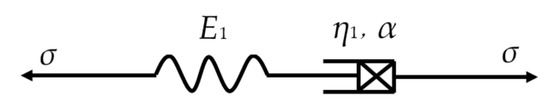
Figure 1.
Fractional-order Maxwell body [17].
Fractional-order Maxwell creep constitutive equation is [25]
where is the elastic modulus of the fractional-order Maxwell body, and is the viscosity coefficient of the fractional-order Maxwell body.
2.2. Viscoplastic Damage Model
Rock creep deformation includes elastic and plastic deformation. When the stress level exceeds a certain threshold (long-term strength), irreversible plastic deformation will occur in rocks. An ideal viscoplastic material can represent the viscoplastic characteristics of rocks, with its mechanical model and curve shown in Figure 2.
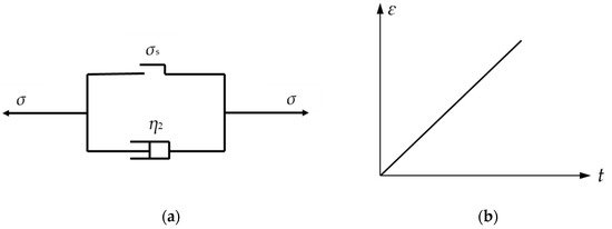
Figure 2.
Ideal viscoplastic body and its curve: (a) viscoplastic body [13]; (b) curve.
The constitutive equation is [13]
where is the long-term strength, and is the viscosity coefficient of the ideal viscoplastic body.
The curve of an ideal viscoplastic material is a straight line, and it cannot reflect the nonlinear features of accelerated creep. In reality, when the stress level exceeds the long-term strength, microcracks within rocks continue to expand with increasing load time, leading to irreversible damage accumulation and resulting in accelerated creep. Based on the theory of damage mechanics, a time-triggered damage body is constructed, as shown in Figure 3.
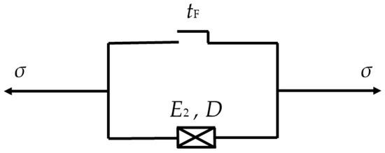
Figure 3.
Damaged body.
If the loading time does not reach tF, the model is turned off, and the damage is negligible. In the interval (tF, +∞), the damage variable D gradually increases to 1 with time. When t = tF, D = 0. when t = +∞, D = 1. The negative exponential function has smooth, monotonically decreasing and bounded properties, which can better describe the process of damage development. It is widely used in creep damage modeling. The damage variable D can be calculated by [31,32]
where D is the damage variable; λ is the damage parameter related to the material, and it is a constant related to the damage development rate. By adjusting the value of the damage parameter related to the material, the growth rate and form of the damage variable can be controlled to adapt to the damage characteristics of the different materials or structures. The choice of the damage parameter should be able to make the model fit well with the experimental data; that is, it can accurately describe the rate of damage development. The value of the damage parameter is determined by comparing with the experimental data so that the model prediction results are as consistent as possible with the experimental observations [19,25]. tF is the acceleration creep start time.
According to Lemaitre strain equivalence principle [33], the time-triggered damage body is expressed as
where E2 is the modulus of elasticity of the damaged body.
To accurately depict the accelerated creep property, a viscoplastic damage model with a double switch of stress and time is formed by connecting the damaged body in series with the viscous element in the ideal viscoplastic body, as illustrated in Figure 4.
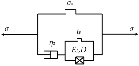
Figure 4.
Viscoplastic damage model.
The constitutive equation of the viscoplastic damage model can be expressed as
where εvp is the strain of the viscoplastic damage model.
2.3. Fractional Creep Damage Model
To describe the nonlinear characteristics of the entire creep process, a fractional creep damage model is formed by connecting the fractional-order Maxwell body in series with the viscoplastic damage model, as illustrated in Figure 5. The strain–time curve is shown in Figure 6.
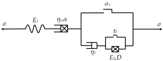
Figure 5.
Fractional creep damage model.
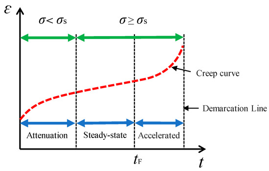
Figure 6.
Strain–time curve.
The creep equation of the fractional creep damage model can be derived by analyzing the tandem system, When , the viscoplastic damage body does not operate, and the model simplifies to a fractional Maxwell model expressed by [25]
When but , the viscous component in the viscoplastic damage body is activated, and the damage body remains closed. The creep equation for this condition is expressed as
When and , the viscoplastic damage body is fully activated, resulting in damage accumulation. The corresponding creep equation is expressed as
For salt rock reservoirs, the rock is usually under three-dimensional stress, necessitating a three-dimensional creep model for practical engineering applications. Assuming isotropy of the rock material [34], the stress tensor () at any point can be divided into deviatoric stress tensor () and spherical stress tensor () using elastic mechanics principles. Likewise, the strain tensor () can be separated into deviatoric strain tensor () and spherical strain tensor ()
where is the Kronecker function, and and are defined, respectively, as follows [24,34]:
For the Hooke body under three-dimensional stress, the constitutive relation can be expressed as [35]
where K is the bulk modulus, and G1 is the shear modulus. According to the generalized Hooke’s law, the three-dimensional constitutive relation of the fractional Maxwell model is [25]
Whether a rock enters viscoplastic deformation under three-dimensional stress is determined by the plastic yield function (F). Combined with the knowledge of geotechnical plastic mechanics, the three-dimensional constitutive equation of the viscoplastic damage model can be obtained as
where F is the yield function; F0 is the initial value of the yield function, generally set as 1; is the shear modulus of the accelerated creep stage; means when F < 0, , when F ≥ 0, ; Q is a plastic potential function, using the associated flow law, taking Q = F.
According to the principle of superposition, the expression of the fractional creep damage model under three-dimensions can be written as
For the conventional triaxial creep test, , so
The stress deviator tensor has a greater effect on the rock creep deformation than the stress sphericity tensor. Therefore, the yield criterion can be selected as [36]
where is the second invariant of the stress bias.
Therefore, the expression for axial strain under three-dimensional stress is
3. Creep Test of Salt Rock
3.1. Specimens and Test Equipment
The specimens used in the test were taken from underground salt mines located at a depth of 1000 to 2000 m. All salt rock samples for the triaxial test were processed into standard cylindrical specimens measuring ϕ50 mm × H100 mm. The specimens were sonically sounded before the test to ensure their homogeneity. Their differences being mainly in the applied loads. Some of rock specimens are shown in Figure 7 below.
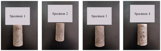
Figure 7.
Salt rock specimens.
The loading equipment used in the mechanical test was the TATW-2000 rock triaxial shear testing machine, as shown Figure 8.
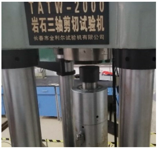
Figure 8.
Test equipment (Rock triaxial shear testing machine produced by Changchun Jinlier Testing Machine Co.).
3.2. Test Protocol and Steps
Four salt rock specimens (1, 2, 3, and 4) were used for conventional triaxial compression tests under single-stage loading with axial stresses of 43, 47, 50, and 53 MPa. The confining pressure was consistently maintained at 30 MPa throughout the tests, and additional uniaxial tests (13 MPa and 23 MPa) and triaxial creep tests (axial stress at 13 MPa and 23 MPa) with a confining pressure of 60 MPa were used to study the effect of confining pressure on the creep behavior, as shown in Table 1.

Table 1.
Loading scheme.
The test steps are as follows:
- Specimen installation: the prepared rock specimen was placed onto the TATW-2000 rock triaxial shear testing machine, with the position of the indenter adjusted to make contact with the rock.
- Load application: according to the test scheme, the confining pressure was first applied, and once stabilized, the axial pressure was applied.
- Data recording and analysis: The computer automatically records the deformation values and plots the change in strain over time. After completion of a test, the specimen was replaced, the above steps were repeated until all tests were completed, and the collected data were sorted and analyzed, ultimately resulting in a strain–time curve under different stress conditions.
3.3. Test Results and Analysis
3.3.1. Creep Curves at Different Deviatoric Stresses
As depicted in Figure 9, the typical creep process of salt rock can be classified into three stages: attenuation, steady state, and accelerated creep. Under low deviatoric stress conditions (e.g., 13 MPa, 17 MPa, and 20 MPa), the salt rock underwent attenuation creep followed by steady-state creep. During the attenuation stage, salt rock undergoes significant deformation as the internal dislocations and defects adjust and reorganize. The strain rate gradually decreased over time until it reached a relatively constant value. The salt rock deformed at a constant rate with no significant change in the microstructure during the steady-state stage. However, under a deviatoric stress of 23 MPa, nonlinear accelerated creep was observed. In this stage, the strain rate increased significantly as a result of increased dislocation activity and deformation mechanisms, such as grain boundary sliding and crack formation. Accelerated creep often leads to a rapid increase in deformation and can result in structural failure if not controlled. The creep rates for the different loading conditions are shown in Figure 10.
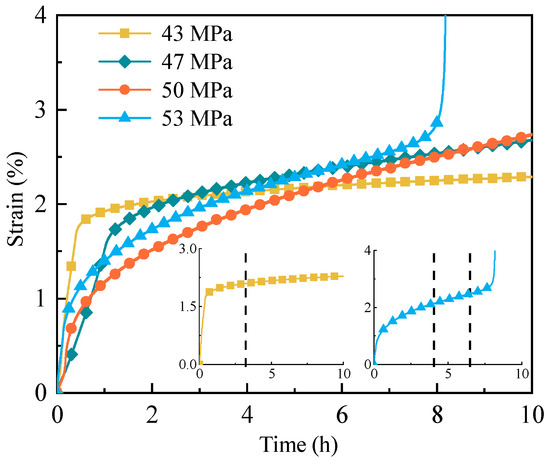
Figure 9.
Creep curves of salt rock with a confining pressure of 30 MPa.
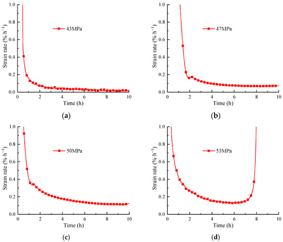
Figure 10.
Creep strain rates of salt rock under a confining pressure of 30 MPa: (a) axial pressure of 43 MPa; (b) axial pressure of 47 MPa; (c) axial pressure of 50 MPa; (d) axial pressure of 53 MPa.
From Figure 10, it can be observed that the larger the axial pressure, the longer the duration of the rock’s softening creep. As the axial pressure increased, the rate of the steady-state creep increased accordingly. Under a constant confining pressure, the greater the axial pressure, the greater the deviatoric stress. This indicates that deviatoric stress is an important factor affecting the triaxial creep mechanical properties of salt rock. Accelerated creep occurs when a rock is subjected to stress beyond its strength limit. High stress induces a rearrangement and slipping of crystals within the rock, resulting in the creation and development of cracks. Consequently, the creep rate increases.
3.3.2. Effect of Confining Pressure
Figure 11 illustrates the creep curves of salt rock subjected to the same deviatoric stress but different confining pressures. Based on the analysis of Figure 11, it is evident that despite variations in the confining pressure among the salt rock specimens, their deformation patterns under loads remained similar. Nonetheless, the precise numeric values of creep curves differed depending on the confining pressure applied. With an increase in the confining pressure, the instantaneous strain, stable creep rate, and the decay radius of the creep curve gradually decreased under the same deviatoric stress conditions. Furthermore, it was observed that when the deviatoric stress was at 23 MPa and the confining pressure was 0 MPa, the rocks entered the acceleration creep stage after approximately 1.5 h and failed approximately 2.5 h later. Similarly, when the confining pressure was 30 MPa, the rocks entered the acceleration creep stage after about 6.5 h and failed approximately 8 h later. However, when the confining pressure reached 60 MPa, the rocks entered the acceleration creep stage after almost 8 h, without any failure occurring during the ensuing 10 h. This indicates that confining pressure can effectively attenuate creep. As the confining pressure decreased, the stable creep stage shortened, and the salt rock failed faster. The duration for entering the acceleration creep stage increased with an increasing confining pressure, and the length of this stage was prolonged correspondingly. The presence of confining pressure in salt rock has two effects. Firstly, it restricts the lateral expansion of the rock, consequently reducing its axial deformation. Secondly, it compacts the existing cracks, slowing down their internal growth. As a result, the time required for the rock to enter the accelerated creep phase increases, and the length of this stage is prolonged correspondingly.
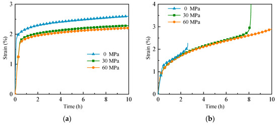
Figure 11.
Creep curves of salt rock with different confining pressures: (a) deviatoric stress of 13 MPa; (b) deviatoric stress of 23 MPa.
3.3.3. Long-Term Strength
Long-term strength is crucial for understanding salt rock creep, and the isochronous stress–strain curve is a commonly employed method to assess it [37]. Figure 12 shows the isochronous stress–strain curves obtained from the creep curve under a 30 MPa confining pressure.
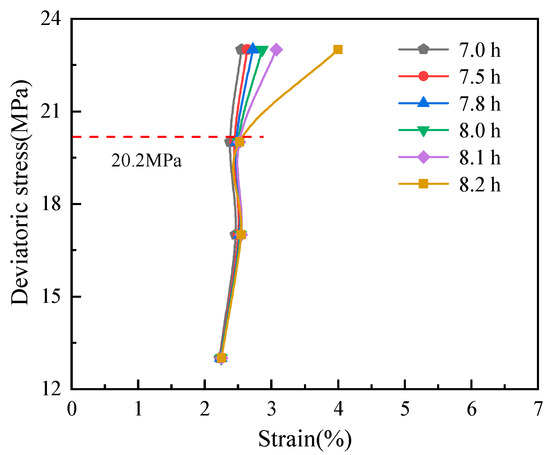
Figure 12.
Isochronous stress–strain curves of a confining pressure of 30 MPa.
As shown in Figure 12, six stress–strain curves at different times were selected. With an increase in the deviatoric stress and time, the curve clusters become sparse. The inflection point in the curve marks the boundary between elasticity and plasticity. The curves are the corresponding stress–strain values at the same moment in time and contain four sets of deviating stresses: 13 MPa, 17 MPa, 20 MPa, and 23 MPa. The long-term strength is the threshold value for producing accelerated creep, so it should be between 20 MPa and 23 MPa. By observing the inflection point in the figure, the inflection point at approximately 17 MPa is convex to the right, which cannot be used as a basis for judging strength, probably because of the inevitable variability among specimens. Therefore, the long-term strength of salt rock under a 30 MPa confining pressure can be determined at 20.2 MPa.
4. Parameter Identification and Model Validation
4.1. Parameter Identification
(1) Determination of K and G1
According to the elastic modulus (E) and Poisson’s ratio, as measured using the compression test (μ), the volume modulus (K) and shear modulus (G1) are determined as
(2) Determination of η2
According to the creep test curve, the slope of the curve (k) of the rock entering the steady creep stage is obtained, and it is determined as
(3) Determination of tF
Accelerated creep start time (tF) is of great significance for rock mass engineering safety early warning and long-term stability monitoring, which can be directly determined with the creep rate.
(4) Determination of η1, α, G2, and λ
The viscoelastic coefficient (η1), fractional order (α), damage body shear modulus (G2), and damage parameters (λ) are determined using the Levenberg–Marquardt algorithm.
4.2. Model Validation
The validation is the triaxial salt rock creep damage model proposed in this paper, as shown in Equation (20) of Section 2.3. To verify the effectiveness of the model, the test data under a confining pressure of 30 MPa were chosen for the parameter fitting, and the parameter values obtained from the fitting are listed in Table 2. Figure 13 shows a comparison of the theoretical curves and test results.
Table 2.
Fitting parameters of test results.
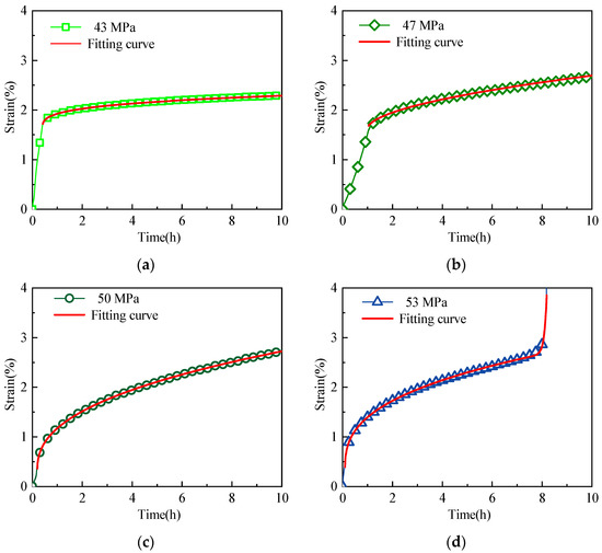
Figure 13.
Comparison of the theoretical curves and test results: (a) axial pressure of 43 MPa; (b) axial pressure of 47 MPa; (c) axial pressure of 50 MPa; (d) axial pressure of 53 MPa.
From Figure 13, it can be seen that the established fractional-order creep damage model is in good agreement with the experimental results. Because of the short duration of the creep experiment, the instantaneous strain time is more pronounced relative to the subsequent creep. During the fitting process, the initial portion of the data points is artificially masked. The model not only accurately describes the stable creep but also characterizes the accelerated creep. With a fitting accuracy of above 0.99, this confirms the rationality and accuracy of the fractional creep damage model.
To further confirm the reliability of the fractional creep damage model, the model parameters were fitted and inverted using the triaxial creep test results of salt rock from the literature [24]. The fitting result was then compared with the classical Nishihara model. The Nishihara model is expressed as [38]
The triaxial creep test was conducted under a confining pressure of 20 MPa with an axial stress of 40 Mpa, and the long-term strength was found to be 19 Mpa. Table 3 shows the creep parameters, and Figure 14 displays the model inversion curve.
Table 3.
Fitting parameters of the fractional-order model and the Nishihara model.
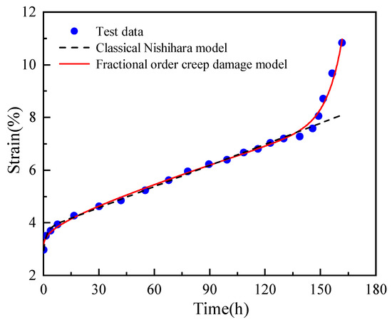
Figure 14.
Comparison of the fitting results between the fractional-order model and the Nishihara model.
The results shown in Table 3 and Figure 14 indicate that both models can effectively reflect the deceleration creep and stable creep phases of salt rock. However, only the fractional creep damage model is capable of describing the accelerated creep phase of salt rock. With a closer fitting accuracy to 1, the fractional creep damage model exhibits a better fitting effect than the classical Nishihara model. This model can accurately describe the different stages of salt creep and fully capture the nonlinear characteristics of salt rock during the accelerated creep phase.
5. Parametric Sensitivity Analysis
Equation (20) indicates that the time-dependent strain of salt rock is affected by parameters such as K, G1, η1, α, η2, G2, λ, and tF. To gain a better understanding of how these parameters impact the creep test results for each stage, a sensitivity analysis was conducted on the key parameters of η1, α, η2, and λ. This analysis was carried out using deviatoric stress loads of 20 MPa and 23 MPa as examples to determine the influence of the fractional derivative parameters on the creep strain of salt rock.
5.1. Parameter η1 Analysis
Equation (20) suggests that η1 has an impact on the creep curve of salt rock during the initial deceleration creep and steady-state creep phases. To analyze how this parameter affects salt rock creep, a fractional derivative approach was used to fit the data based on the deviatoric stress of 20 MPa (as indicated in Table 1) while controlling only the variable η1. The results of this analysis are presented in Figure 15.
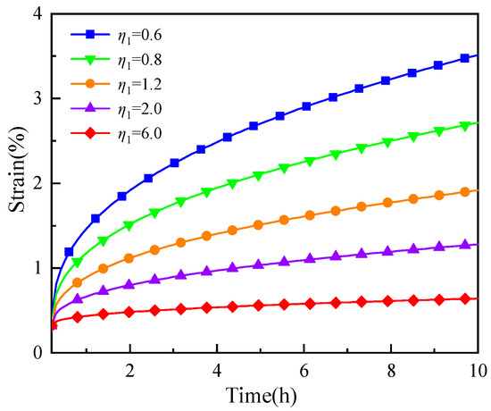
Figure 15.
Effect of parameter η1 (GP·h) on creep curve.
As illustrated in Figure 15, the change in η1 had no effect on the initial transient creep stage. However, when η1 increased, the creep curve’s points moved downwards, and its attenuation tendency reduced. This resulted in a shorter deceleration creep phase and a lower rate of steady-state creep phase. This is because as η1 increased, the viscosity characteristic decreased, resulting in a lower deformation rate under a constant load and a corresponding reduction in rock deformation.
5.2. Parameter α Analysis
Figure 16 displays the influence of different α values on the creep curve. Only the α value was changed, with the remaining parameters consistent with those outlined in Table 2 for a deviatoric stress of 20 MPa.
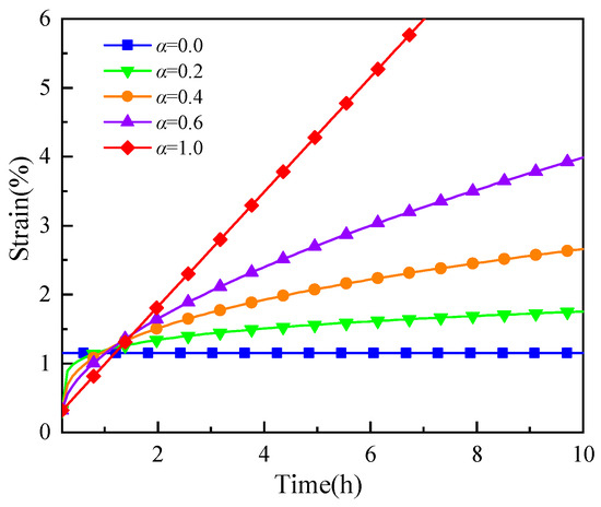
Figure 16.
Effect of parameter α on the creep curve.
As shown in Figure 16, the starting point was the same except for α = 0. The value of α affects the order of the fractional derivative. When α = 0, the component is an ideal elastic body that describes the strain as a constant value. With the decrease in the value of α, the nonlinear characteristics of the creep curve become increasingly obvious. When α = 1, the component became an ideal viscous body. This indicates that the parameter α also affects the deceleration creep and steady-state creep phases. Different from parameter η1, the creep rate increased as parameter α increased.
5.3. Parameter η2 Analysis
The relationship between the parameter η2 and the creep curve is shown in Figure 17. Only the η2 value was changed, with the remaining parameters consistent with those outlined in Table 3.
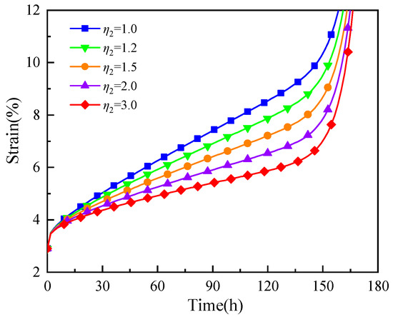
Figure 17.
Effect of parameter η2 (GP·h) on the creep curve.
As can be seen from Figure 17 above, the parameter η2 had no effect on the initial attenuation creep stage, but it affected the steady-state creep phase. With the increase in η2, the lower the constant velocity creep rate, and the creep deformation also reduced accordingly. This led to a reduction in the accelerated creep deformation. This is because as η2 increased, the viscosity characteristic of the steady-state creep phase decreased.
5.4. Parameter λ Analysis
The influence of the different values of parameter λ on the creep curve is shown in Figure 18.
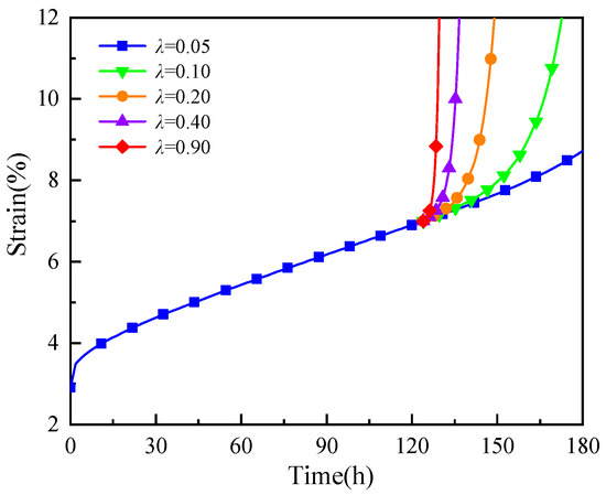
Figure 18.
Effect of parameter λ on the creep curve.
As can be seen from Figure 18, the parameter λ only affected the accelerated creep phase. The strain increased with the increase in the parameter λ. This was due to the increased susceptibility of the rock to damage as λ increased, which accelerated the accumulation of damage and reduced the time until failure. As a result, the accelerated creep process of the rock became more obvious.
In summary, the fractional-order creep damage model established in this paper has a simple form and clear physical meaning of parameters, which can describe different forms of creep deformation by changing the values of different parameters.
6. Discussion
One limitation of the proposed creep damage model is the assumption of ideal laboratory conditions during indoor testing. These controlled settings often differ from the complex and dynamic conditions found in the field. Factors such as varying stress levels, temperature fluctuations, and heterogeneous material properties can significantly affect the creep behavior of rocks or materials. Furthermore, the model may rely on specific input parameters that are more readily available in laboratory settings but may be challenging to measure or estimate accurately in field conditions. Variations in sample preparation, specimen size, and boundary conditions in the field can introduce uncertainties in the model predictions. Additionally, the proposed model may not account for all the possible mechanisms or factors that influence creep deformation in field scenarios. The complexity of real-world conditions, including the presence of geological structures, cyclic loading, and long-term environmental effects, can introduce additional variables that are not fully captured in the model.
To address these limitations, future research should focus on expanding the model’s applicability to field conditions. This may involve incorporating field data and conducting extensive field testing to validate and calibrate the model parameters. By considering site-specific characteristics and refining the model based on field observations, we can enhance its accuracy and reliability for practical applications.
7. Conclusions
In this paper, we propose a novel triaxial fractional-order creep damage model that takes into account plastic deformation during the steady-state creep stage. To validate the model, uniaxial and triaxial creep experiments were conducted on salt rock at various stress levels. The model was then subjected to a parameter sensitivity analysis. The main conclusions are as follows:
(1) To incorporate plastic deformation during the steady-state creep phase, a viscoplastic damage body controlled by time and stress is constructed. This viscoplastic damage body is connected in series with the fractional-order Maxwell model, resulting in a comprehensive fractional-order creep damage model that describes the entire creep phase. The three-dimensional model is derived by combining the Mises yielding criterion.
(2) The creep rate of salt rock increases with deviatoric stress, and a distinct accelerated creep stage is observed when the stress exceeds the long-term strength. Additionally, increasing the confining pressure leads to a decrease in both the creep rate and deformation. The application of confining pressure effectively mitigates the creep deformation and reduces the tendency for accelerated creep.
(3) To validate the proposed new model, triaxial creep test results were employed. The validation process reveals that the new model not only better reflects the creep characteristics of the rock at different stages but also provides parameters with clearer interpretations that are more suitable for the test results compared to the classical model. Furthermore, the new model accounts for plastic deformation during the steady-state creep stage, making it more universally applicable.
(4) Different parameters have distinct effects on the creep curve. The parameter η1 characterizes the transition from attenuation to steady-state creep by controlling the magnitude of viscosity. The parameter α modifies the viscoelastic properties by adjusting the fractional order. The parameter η2 governs deformation during the steady-state creep stage by modifying the viscosity of the plastic component, while the parameter λ controls various forms of accelerated creep deformation by regulating the damage rate.
Author Contributions
Conceptualization, X.Z. and H.C.; validation, H.C., J.L. and X.H.; formal analysis, X.Z. and Y.Q.; data curation, X.Z. and H.C.; writing—original draft preparation, H.C.; writing—review and editing, X.Z.; supervision, K.S.; funding acquisition, X.Z. All authors have read and agreed to the published version of the manuscript.
Funding
This research was funded by the National Natural Science Foundation of China, grant number: 52104004.
Institutional Review Board Statement
Not applicable.
Informed Consent Statement
Not applicable.
Data Availability Statement
Data will be made available on request.
Conflicts of Interest
The authors declare no conflict of interest.
References
- Gao, R.B.; Wu, F.; Chen, J.; Zhu, C.; Ji, C.X. Study on creep characteristics and constitutive model of typical argillaceous salt rock in energy storage caverns in China. J. Energy Storage 2022, 50, 104248. [Google Scholar] [CrossRef]
- Wang, X.K.; Song, L.B.; Xia, C.C.; Han, G.S.; Zhu, Z.M. Nonlinear elasto-visco-plastic creep behavior and new creep damage model of dolomitic limestone subjected to cyclic incremental loading and unloading. Sustainability 2021, 13, 12376. [Google Scholar] [CrossRef]
- Chen, F.; Ye, L.L.; Ma, H.L.; Shi, X.L.; Liu, H.D.; Yang, C.H. Subsidence above gas storage in salt caverns predicted with viscoelastic theory. J. Nat. Gas Sci. Eng. 2022, 103, 104620. [Google Scholar] [CrossRef]
- Li, J.C.; Wan, J.F.; Liu, H.M.; Jurado, M.J.; He, Y.X.; Yuan, J.G.; Xia, Y. Stability Analysis of a Typical Salt Cavern Gas Storage in the Jintan Area of China. Energies 2022, 15, 4167. [Google Scholar] [CrossRef]
- Ma, L.J.; Wang, Y.X.; Wang, M.Y.; Xue, B.; Duan, L.Q. Mechanical properties of rock salt under combined creep and fatigue. Int. J. Rock Mech. Min. Sci. 2021, 141, 104654. [Google Scholar] [CrossRef]
- Wang, J.B.; Zhang, Q.; Liu, X.; Son, Z.P.; Feng, S.J. Creep properties and constitutive model for salt rock subjected to uniaxial trapezoidal cyclic loading. J. Energy Storage 2022, 52, 105023. [Google Scholar] [CrossRef]
- Nawrocki, P.A.; Mroz, Z. A viscoplastic degradation model for rocks. Int. J. Rock Mech. Min. Sci. 1998, 35, 991–1000. [Google Scholar] [CrossRef]
- Ma, J.J. An Elasto-Viscoplastic Model for Soft Porous Rocks Within the Consistent Framework. Rock Mech. Rock Eng. 2017, 50, 3109–3114. [Google Scholar] [CrossRef]
- Ma, J.J.; Guan, J.W.; Gui, Y.L.; Huang, L.C. Anisotropic Bounding Surface Plasticity Model for Porous Media. Int. J. Geomech. 2021, 21, 04021033. [Google Scholar] [CrossRef]
- Zienkiewicz, O.C.; Cormeau, I.C. Visco-plasticity–plasticity and creep in elastic solids–a unified numerical solution approach. Int. J. Numer. Methods Eng. 1974, 8, 821–845. [Google Scholar] [CrossRef]
- Ma, J.J.; Chen, J.J.; Chen, W.X.; Huang, L.C. A coupled thermal-elastic-plastic-damage model for concrete subjected to dynamic loading. Int. J. Plast. 2021, 21, 103279. [Google Scholar] [CrossRef]
- Cristescu, N.D. A general constitutive equation for transient and stationary creep of rock salt. Int. J. Rock Mech. Min. Sci. 1993, 30, 125–140. [Google Scholar] [CrossRef]
- Zhou, H.W.; Wang, C.P.; Han, B.B.; Duan, Z.Q. A creep constitutive model for salt rock based on fractional derivatives. Int. J. Rock Mech. Min. Sci. 2011, 48, 116–121. [Google Scholar] [CrossRef]
- Deng, H.L.; Zhou, H.W.; Wei, Q.; Li, L.F.; Jia, W.H. A creep constitutive model based on Atangana–Baleanu fractional derivative. Mech. Time-Depend. Mater. 2022. [Google Scholar] [CrossRef]
- Chen, J.; Lu, D.; Wu, F.; Fan, J.Y.; Liu, W. A non-linear creep constitutive model for salt rock based on fractional derivatives. Therm. Sci. 2019, 23, S773–S779. [Google Scholar] [CrossRef]
- Lyu, C.; Liu, J.F.; Ren, Y.; Liang, C.; Liao, Y.L. Study on very long-term creep tests and nonlinear creep-damage constitutive model of salt rock. Int. J. Rock Mech. Min. Sci. 2021, 146, 104873. [Google Scholar] [CrossRef]
- Zhou, H.W.; Liu, D.; Lei, G.; Xue, D.J.; Zhao, Y. The creep-damage model of salt rock based on fractional derivative. Energies 2018, 11, 2349. [Google Scholar] [CrossRef]
- Wu, F.; Zhou, X.H.; Ying, P.; Li, C.B.; Zhu, Z.M.; Chen, J. A Study of uniaxial acoustic emission creep of salt rock based on improved fractional-order derivative. Rock Mech. Rock Eng. 2022, 55, 1619–1631. [Google Scholar] [CrossRef]
- Gao, Y.H.; Zhou, Z.; Zhang, H.; Jin, S.; Yang, W.; Meng, Q.H. Viscoelastoplastic displacement solution for deep buried circular tunnel based on a fractional derivative creep model. Adv. Civ. Eng. 2021, 2021, 3664578. [Google Scholar] [CrossRef]
- Kamdem, T.C.; Richard, K.G.; Béda, T. New description of the mechanical creep response of rocks by fractional derivative theory. Appl. Math. Model. 2023, 116, 624–635. [Google Scholar] [CrossRef]
- Shen, M.; Zhou, Z.; Ma, W. Experimental and Theoretical Investigation on the Unloading Creep Behaviors of Frozen Soil. Rock Mech. Rock Eng. 2023. [Google Scholar] [CrossRef]
- Yin, Z.; Zhang, X.; Liu, Y.; Yu, H.; Zhang, Q.S.; Li, X.H. A fractional-order damage creep model for grouting-reinforcement body under dry–wet cycle. Bull. Eng. Geol. Environ. 2023, 82, 172. [Google Scholar] [CrossRef]
- He, Q.C.; Wu, F.; Gao, R.B. Nonlinear creep-damage constitutive model of surrounding rock in salt cavern reservoir. J. Energy Storage 2022, 55, 105520. [Google Scholar] [CrossRef]
- Wu, F.; Liu, J.; Zou, Q.L.; Li, C.B.; Chen, J.; Gao, R.B. A triaxial creep model for salt rocks based on variable-order fractional derivative. Mech. Time-Depend. Mater. 2020, 25, 101–118. [Google Scholar]
- Lyu, C.; Liu, J.; Zhao, C.X.; Ren, Y.; Liang, C. Creep-damage constitutive model based on fractional derivatives and its application in salt cavern gas storage. J. Energy Storage 2021, 44, 103403. [Google Scholar] [CrossRef]
- Yu, M.Y.; Liu, B.G.; Liu, K.Y.; Sun, J.L.; Deng, T.B.; Wang, Q. Creep behavior of carbonaceous mudstone under triaxial hydraulic coupling condition and constitutive modelling. Int. J. Rock Mech. Min. Sci. 2023, 164, 105357. [Google Scholar] [CrossRef]
- Zhang, L.; Zhou, H.W.; Wang, X.Y.; Deng, T.F.; Chen, C.F.; Zhang, H.; Nagel, T. Modeling the visco-elastoplastic behavior of deep coal based on conformable derivative. Mech. Time-Depend. Mater. 2023. [Google Scholar] [CrossRef]
- Adolfsson, K.; Enelund, M.; Olsson, P. On the fractional order model of viscoelasticity. Mech. Time-Depend. Mater. 2005, 9, 15–34. [Google Scholar] [CrossRef]
- Sapora, A.; Cornetti, P.; Carpinteri, A.; Baglieri, O.; Santagata, E. The use of fractional calculus to model the experimental creep-recovery behavior of modified bituminous binders. Mater. Struct. 2016, 49, 45–55. [Google Scholar] [CrossRef]
- He, Z.L.; Zhu, Z.D.; Ni, X.H.; Li, Z.J. Shear creep tests and creep constitutive model of marble with structural plane. Eur. J. Environ. Civ. Eng. 2019, 23, 1275–1293. [Google Scholar] [CrossRef]
- Chen, L.; Wang, C.P.; Liu, J.F.; Liu, Y.M.; Liu, J.; Su, R.; Wang, J. A damage-mechanism-based creep model considering temperature effect in granite. Mech. Res. Commun. 2014, 56, 76–82. [Google Scholar] [CrossRef]
- Wu, F.; Zhang, H.; Zou, Q.; Li, C.; Chen, J.; Gao, R. Viscoelastic-plastic damage creep model for salt rock based on fractional derivative theory. Mech. Mater. 2020, 150, 103600. [Google Scholar] [CrossRef]
- Lemaitre, J. A continuous damage mechanics model for ductile fracture. J. Eng. Mater. Tech. 1985, 107, 83–89. [Google Scholar] [CrossRef]
- Wang, J.; Zhang, Q.; Song, Z.; Feng, S.J.; Zhang, Y.W. Nonlinear creep model of salt rock used for displacement prediction of salt cavern gas storage. J. Energy Storage 2022, 48, 103951. [Google Scholar] [CrossRef]
- Liu, J.S.; Jin, H.W.; Meng, B.; Wang, L.G.; Yang, J.J.; You, Y.W.; Zhang, S.J. Fractional-order creep model for soft clay under true triaxial stress conditions. Arab. J. Geosci. 2020, 13, 834. [Google Scholar]
- Zhang, L.; Zhou, H.W.; Wang, X.Y.; Wang, L.; Su, T.; Wei, Q.; Deng, T.F. A triaxial creep model for deep coal considering temperature effect based on fractional derivative. Acta Geotech. 2022, 17, 1739–1751. [Google Scholar] [CrossRef]
- Huang, T.Z.; Li, J.L.; Zhao, B.Y. Nonlinear creep damage model of rock salt considering temperature effect and its implement in FLAC3D. Geomech. Eng. 2021, 26, 581–591. [Google Scholar]
- Jiang, Q.; Qi, Y.; Wang, Z.; Zhou, C.B. An extended Nishihara model for the description of three stages of sandstone creep. Geophys. J. Int. 2013, 193, 841–854. [Google Scholar] [CrossRef]


Disclaimer/Publisher’s Note: The statements, opinions and data contained in all publications are solely those of the individual author(s) and contributor(s) and not of MDPI and/or the editor(s). MDPI and/or the editor(s) disclaim responsibility for any injury to people or property resulting from any ideas, methods, instructions or products referred to in the content. |
© 2023 by the authors. Licensee MDPI, Basel, Switzerland. This article is an open access article distributed under the terms and conditions of the Creative Commons Attribution (CC BY) license (https://creativecommons.org/licenses/by/4.0/).