Article

Evaluation of Ca-Based Sorbents for Gaseous HCl Emissions Adsorption

Department of Environment, Land and Infrastructure Engineering, Politecnico di Torino, Corso Duca degli Abruzzi 24, 10129 Turin, Italy
*
Authors to whom correspondence should be addressed.
Sustainability 2023, 15(14), 10882; https://doi.org/10.3390/su151410882
Submission received: 14 June 2023 / Revised: 7 July 2023 / Accepted: 10 July 2023 / Published: 11 July 2023

Abstract

:
The problem of acid gas exhaust emissions treatment has not been fully resolved at present. Dry adsorption of acid gases with alkaline sorbents is currently being investigated, to improve solid sorbents. In this study, 5 types of hydrated lime were characterised and tested. The sorption capacities were measured by means of a system consisting of a feed line (HCl/N2), a thermostatic reactor and a water absorber. The physical characteristics of sorbent samples were also compared. Analyses conducted with scanning electronic microscopy revealed that sample C1 showed uniform particle distribution. Samples C2 and C3 showed the co-presence of fine and coarse particles. Sample C4 showed very fine particles with agglomeration phenomena. In sample C5, fibrous elements were found. Energy dispersive spectrometry (EDS) analyses showed a similar composition of the samples, with the exception of the presence of Mg in some of them. After 30 min of testing, the following differences in sorption capacities with respect to C1 (3.59 mg g−1) were found: C2, −20%; C3, −13%; C4, −17%; C5, −3%. Higher sorption capacities were associated with more uniform particle size distributions. Conversely, agglomeration of fine particles may have adversely affected the performance of sorbents.

1. Introduction

For many industries, especially the waste-to-energy (WtE) sector, the efficient control of air pollution is still subject to many technological and scientific innovations. WtE facilities emit a wide variety of pollutants, which have the potential to be hazardous to both human health and ecological integrity [1]. The WtE sector is typically subject to strict emission regulations and the Best Available Techniques Reference Documents (BREF WI; [2]) set ambitious emission reduction targets [3,4].
In order to prevent potential impacts on the environment and human life, reducing acid gases, organic pollutants, and heavy metals is crucial [5]. The impact of acid gases inside WtE plants and their link to corrosion issues are well documented [6]. Table 1 reports the main advantages and limitations of acid gas abatement technologies.
In the last 20 years, dry or semi-dry adsorption systems have developed into effective and powerful systems for achieving lower emissions. Both dry and semi-dry systems typically include a reaction area with an additive supply, and a dust collector (electrostatic precipitators and/or fabric filters) [8]. In case a conditioning phase is included, the separation of the pollutants via deposition on lime is ameliorated by a hydrate shell which is formed around (and inside the pores of) the lime particles and results from the water contained in the flue gas [7]. Wet absorption systems work by using scrubbers of various designs, such as spray scrubbers, Venturi scrubbers, or packed scrubbers. Each of the methods has its own particular advantages and disadvantages, depending on the conditions of the process and installations [9].
The composition of the processed wastes, the design of the WtE facility and the operation techniques employed have a substantial impact on the amount of the acid components in flue gases. One of the pollutants emitted from incinerators, HCl, is known to cause high-temperature corrosion when the temperature exceeds 370 °C. HCl is also known to cause low-temperature corrosion that can easily corrode metals after condensation when the dew point temperature drops below about 140 °C [10]. The HCl emitted into the atmosphere has negative effects on human health, as it stimulates the upper airways causing cough and dyspnea. The presence of HCl in the atmosphere also accelerates the generation of halocarbons [11].
The simultaneous gas/solid adsorption reaction used in the dry system to separate HCl from flue gas results in the binding of the gaseous pollutants to the surface of the added solid. In order to separate polychlorinated dibenzodioxins (PCDD), polychlorinated dibenzofurans (PCDF) and heavy metals, dry techniques additionally permit the dispersion of lignite coke or activated carbon, in a dried form, into the flue gas stream. Based on the additive used, dry systems are classified either as sodium-based (using Na-HCO3) or lime-based (using Ca(OH)2) systems. The reactions occurring in the acid gas removal process are reported in Table 2. Equations (1)–(3) describe the reaction mechanism of calcium-based sorbents. Equations (4)–(6) describe the reaction mechanism of sodium-based sorbents. The ideal operating temperature for lime-based sorbents is between 140 and 150 °C, while this temperature can be lowered further with limited risk of condensation. At temperatures between 170 and 180 °C, sodium-based sorbents show the highest sorption capacity [12]. After reacting, solid sorbents and dust particles can be removed from the flue gas using a fabric or baghouse filter. The creation of a filter cake is essential for the de-dusting process, as it affects the retention period of the additive and, consequently, the contact time of additives and pollutants in the exhaust gas. The specific surface area of the solid (m2 kg−1 reagent), the degree of gas mixing, the concentration of the gas to be adsorbed, the temperature and humidity of the flow, and the concentration of the reagent—typically described in terms of stoichiometric ratio—all have an impact on the efficiency of adsorption processes [13]. In order to achieve the same yields as wet systems, dry scrubbing systems must use significantly more reagents, necessitating at least a partial recirculation of the separated solids. Although the disposal of solid residues generates issues, these systems operate without liquids and the associated problems of fouling and corrosion [14].
In many process industries Mg-based sorbents, namely, Mg(OH)2 or some sparingly soluble salt of this metal are also being used, in particular for the desulfurization of flue gases due to its high SO2 adsorption capacity and ease of regeneration [7]. Sodium-based sorbents allow, in general, higher collection efficiency than lime, but they are more expensive. In addition, the sorption reaction of NaHCO3 involves the production of CO2, which worsens the greenhouse gas (GHG) balance of the plant. Regarding calcium-based sorbents, the large quantity of additives that this type of process consumes is counterbalanced by their limited price, and therefore makes this type of process interesting from an economic point of view. In addition, if these materials are used in properly operated two-stage systems, significant savings in the cost of operation can be achieved with respect to single-stage bicarbonate-fed systems [3]. Current research on dry acid flue gas adsorption is focusing on improving both process and sorbents. Recently, new formulations of calcium and sodium based sorbents have been investigated [15].
The improvement of solid sorbents is focused on two main aspects: the first is increasing the specific surface of the material and the second is modifying the properties of the material. Different technical processes can be applied for increasing the reactive surface. Such processes aim at breaking up the agglomerations, e.g., ball milling, or deflection bends in the flue gas duct [16]. The modification of the properties of the material can be obtained by different mechanical or chemical processes, such as activation with organic or inorganic materials, mixing with other adsorbents/absorbents (e.g., activated carbon), and modification of the surface or pore structures [17]. It is also possible to significantly enlarge the specific surface of calcium hydroxide by adding a mixture of organic solvents and water to the CaO slaking water [18]. Other factors, including the concentration of HCl in the flue gas, and the air velocity, also affect the reaction between the sorbent and HCl in addition. The adsorption efficiency may be improved by altering the sorbent particle diameter or by altering the process to lengthen the time the sorbent is in contact with the HCl to ensure a more complete reaction [19].
Most recent research studies also addressed improving the simultaneous sorption of HCl and other acid gases, with a particular focus on desulfurization. Some researchers investigated HCl and SO2 dry adsorption and found that the adsorption of HCl, like SO2, was increased at low temperatures [20]. A higher relative humidity of the gas also enhanced the sorption capacity [21]. Other investigations reported that the fraction of hydrated lime converted by SO2 increased as the SO2/HCl feed ratio increased [20]. Zhou et al. [22] reduced the particle and grain sizes of Ca (OH)2 by ball milling, which increased the active sites of Ca(OH)2. After this modification, SO3 sorption per mg of Ca(OH)2 increased by 40%. The sorption capacity of Ca(OH)2 was improved by adding ions during the ball milling process. Chin et al. [23] investigated the effects of other species present in the flue gas, namely, CO2, SO2, and moisture, on the HCl-lime reaction. on a short-time basis (<1 min), CO2 and SO2 did not affect the HCl sorption. On a longer time basis, the quantity of HCl adsorbed by lime was decreased due to the presence of CO2 and SO2, because the diffusion of the gas to the unreacted sorbent layer was impeded. The presence of HCl, however, helped with the removal of SO2 and CO2 by lime. The objective of the present study was the characterization of the samples and the quantification of the dry sorption capacity of HCl gaseous emissions of five different formulations of calcium-based sorbents based on the same operating conditions. This study was conducted with the purpose of achieving lower HCl emission rates into the atmosphere and minimizing solid waste production, i.e., lowering the amount of spent sorbent that is disposed to landfill. To this end, an experimental installation was designed and applied. The initial composition and preparation method of the samples was unknown. Samples were provided by an industrial partner based in Northern Italy. The composition and preparation method were thus not disclosed as it is subjected to the right of confidentiality by the owner. This aspect implies a change of perspective with respect to currently published studies, in which a new formulation is usually evaluated against a standard sorbent sample. In contrast, in this study, the aim was to observe, evaluate and compare the characteristics of different samples of unknown composition and formulation, trying to identify the elements that could have the greatest influence on sorption capacity. This represented an element of innovation with respect to the current state of the art.

2. Materials and Methods

2.1. Experimental Test

The tests were conducted using an experimental set up that simulates the operating conditions present in Duct Injection Sorbent (DSI) systems, particularly when the sorbent is retained in the bag filter and interacts with the acid gas passing through the filter. A picture of the installation is reported in Figure 1.
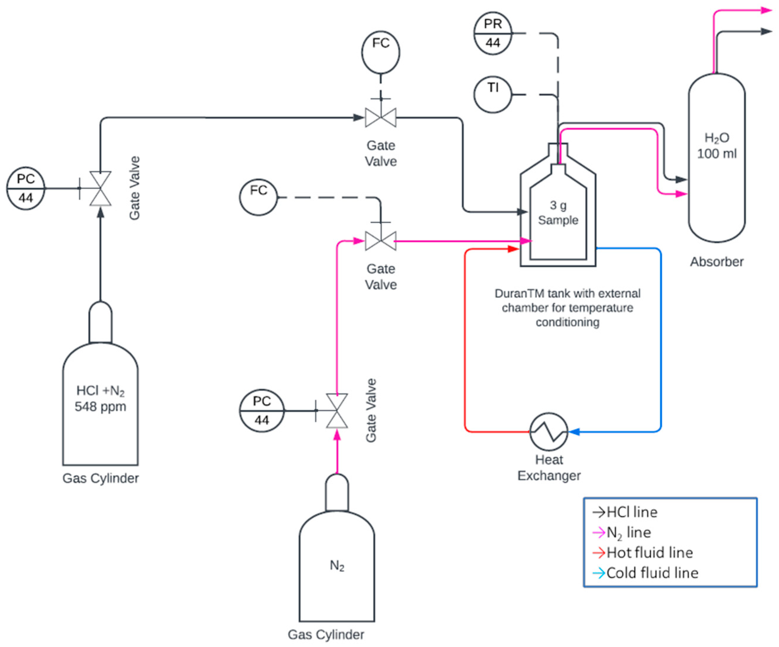
The experimental installation was designed to minimize the undesired reactions of HCl with the apparatus materials. In fact, HCl is highly reactive and corrosive. The unit included two input pipelines fed by gas cylinders. Piping lines were in PTFE, 6 mm in diameter. The first line served as an input of the acid gas. A mixture of HCl and nitrogen, specifically designed for these tests, was used. HCl concentration in the mixture was 548 ppm. The second line provided a pure nitrogen gas flow. Nitrogen was employed to wash the system for 3 min after each test to remove residual HCl. The input line pressure was measured by a pressure sensor. The pressure was 20 mbar during the tests. The input flow was regulated with a flowmeter (Dwyer DR1-012435) to 0.5 L min−1. The flow velocity was 0.3 m s−1. The HCl/N2 gas was injected continuously in a sealed Duran® (Wertheim, Germany) glass bottle containing the solid sorbent to be tested. Five different types of calcium-based sorbents were tested. A mass of 3 g of sorbent was used for each test. The sorbent was uniformly distributed over the bottom of the bottle in order to create a layer of approximately 5 mm of thickness. This was done to simulate the thickness of the dust cake that is commonly reached on a baghouse filter before the cleaning mechanism enters into operation. Five test replicates were made for each sample. Outliers (highest and lowest results) were discarded. For temperature conditioning, the bottle was placed in a Duran® glass reactor with a thermal chamber connected to a heat exchanger (Lauda RP 250, Istanbul, Turkey). The heat exchanger uses a closed loop circuit in which a thermal fluid flows to keep constant temperature. Tests were done at 25 °C. The temperature of the reactor was monitored with a type-K thermocouple connected to an Arduino device and a Matlab script. The unreacted HCl exiting the bottle entered a borosilicate glass absorber containing 100 mL ultrapure water. In the glass absorber, part of the unreacted HCl was retained. At fixed time steps, 2.5 mL of the absorbing water was extracted from the absorber, and the chloride concentration was measured with an ion chromatograph. The gas exiting the water absorber was finally vented to the atmosphere. PTFE tubes were used for the gas and heating lines, in order to avoid corrosion phenomena and undesired reactions. The whole equipment was connected to a ventilated hood to avoid the possible risk of HCl inhalation in case of undesired escape. The process scheme of the experimental installation is reported in Figure 2. The process instrumentation includes two gate valves for the control of high pressure feed lines, a flow regulator, and temperature and pressure monitors.
The sorption capacity of each sorbent was determined by measuring the concentration of chlorides absorbed in the water. Chloride concentration in the absorption water was measured by mean of an ion chromatograph (ECO IC by Metrohm, Herisau, Switzerland). The column for the determination of chlorides was a MetrosepA Supp17, length 250.0 mm, ID 4.0 mm, eluent 5.0 mmol L−1 of Na2CO3 and 0.2 mmol L−1 of NaHCO3; workflow 0.6 mL min−1 at 25 °C. The complete duration of each test was 30 min. In each test, samples of the absorption water were taken after 5, 10, 20, and 30 min and the chloride concentration was measured. To determine the efficiency of the water absorption phase, a number of tests were carried out without sorbent. The resulting absorber efficiency was 56%.
Sorbent samples were also analyzed by mean of scanning electronic microscopy (SEM). The SEM used was a FEI (FEI Company, Hillsboro, OR, USA) operating at 20 kV. This technology allows a resolution of around 0.01 µm. A small amount of each sample (8 g) was mixed in 100 mL of acetone, adding a drop of flocculant. Then, for sample dispersion, the mixture was placed in an ultrasonic bath. Subsequently, 10 mL of solution was filtered on a 0.45 µm Nylon membrane.

2.2. Determination of the Sorption Capacity

Given the experimental conditions, the sorption unit can be considered as a continuous stirred tank reactor (CSTR). Within the reactor, the contact between hydrochloric acid and the sample takes place, according to reaction (1) of Table 2. By deriving the amount of chlorides input, knowing the efficiency of the absorber and measuring the concentration after the test in the absorber, it is possible to determine the number of chlorides adsorbed by the hydrated lime sample.
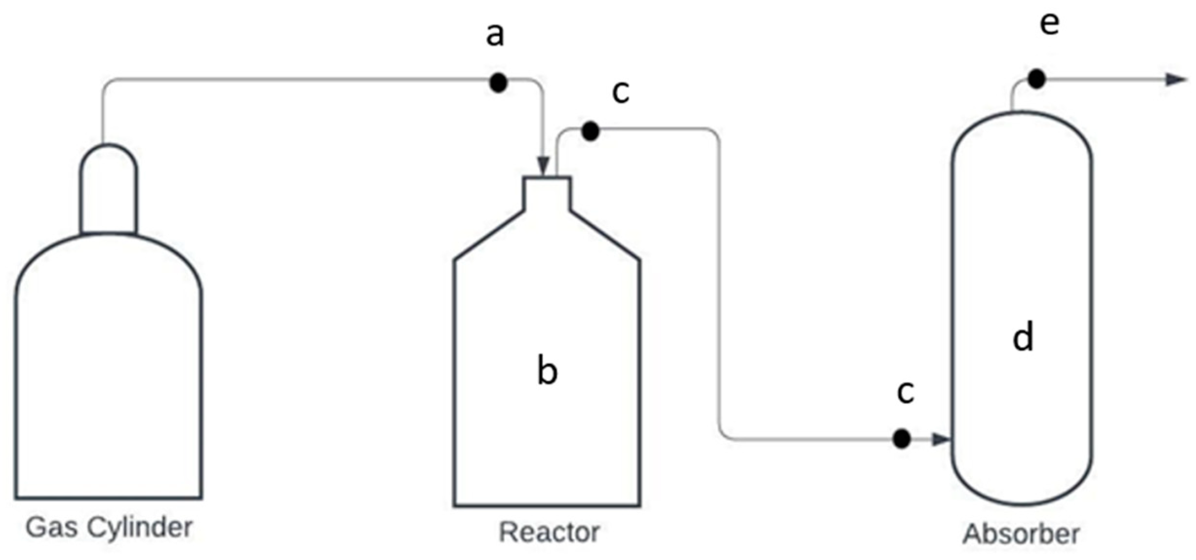
With reference to Figure 3, under conditions of constant temperature and flow, the number of chlorides absorbed over time is defined by Equation (7):
d M b d t = q a q c    
where dMb/dt is the variation of chlorides mass inside the reactor, qa is the incoming mass flow of chlorides to the reactor, and qc is the chlorides mass flow leaving the reactor. By integrating dMb/dt in time, it is possible to define the accumulated mass Mb at the end of the test time (tf) as the difference between the total incoming mass Ma and the total outgoing mass Mc (Equations (8)–(10))
M b = M a M c
M a = 0 t f q a d t
M c = 0 t f q c d t
At the end of each test, a small volume (2.5 mL) of solution was extracted by the absorber with a syringe (Figure 3, position d) and inserted into the ion chromatograph to measure the chloride concentration absorbed from the water column. Multiplying the measured concentration Cd by the volume of solution Vd gives the mass of chlorides absorbed Md at the end of the test as described in Equation (11):
M d = C d   V d
Given the absorbed mass Md and the absorber efficiency (ƞ = 0.56), the mass leaving the system (Me) and the mass entering the absorber (Mc) at the end of the test can be derived with the following Equations (12) and (13):
M e = M c ( 1 ƞ )
M c = M d ƞ
The mass entering the absorber is the same as the mass exiting from the reactor (Mc) thus Mb is calculated by mean of Equation (8).

3. Results

3.1. SEM Analyses

In order to better understand the nature of the tested samples and for a more complete interpretation of the sorption tests, scanning electron microscopy (SEM) analyses were carried out. The results of these analyses consist of the acquisition at different magnifications of the samples in order to visually assess the appearance of the particles. Also, the technique allows energy-dispersive spectrometry analyses to define the chemical composition of the samples.
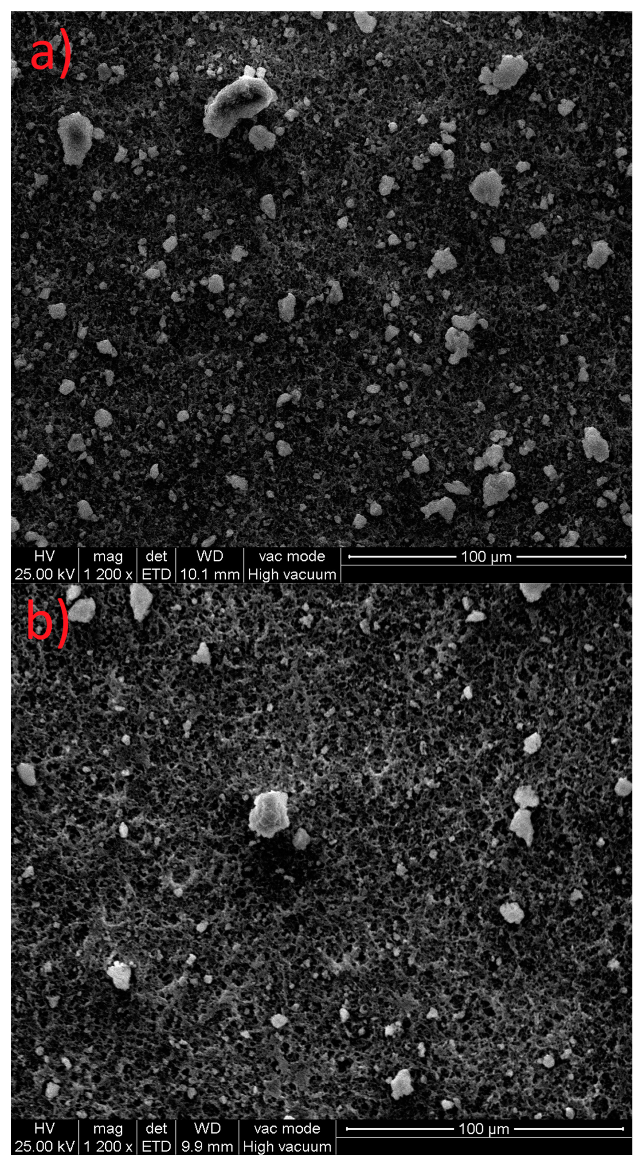
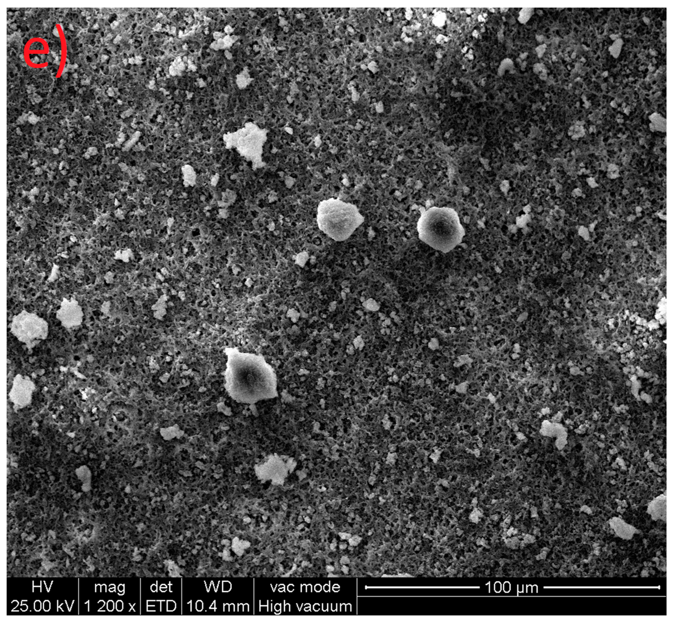
SEM pictures of the calcium hydroxide samples at a 1200× magnification are reported in Figure 4. All samples showed a common main feature, i.e., the presence of both fine and coarse particles. Fine particles seem to constitute the main solid matrix, while granules with a seemingly crystalline structure possibly constitute a minor component. Sample 1 (Figure 4a) shows rather uniform size distribution. Enlarging magnification up to 20,000× allowed us to measure the average size of fine dust particles, which is approximately 1–5 microns. Sample 2 (Figure 4b) appears more heterogeneous than other samples. Also, for sample 2 and sample 3 (Figure 4c), the difference in size between the granules and fine powder seems greater than in other samples. Sample 4 (Figure 4d) showed smaller particle sizes that tend to agglomerate, forming a so-called “cauliflower structure” that has been observed in previous studies [16]. The difference in consistency of Sample 4 with respect to other samples could be perceived also during sample handling. In the analysis of Sample 5 (Figure 4e), tubular fibers of unknown origin, made of organic material, were also detected.
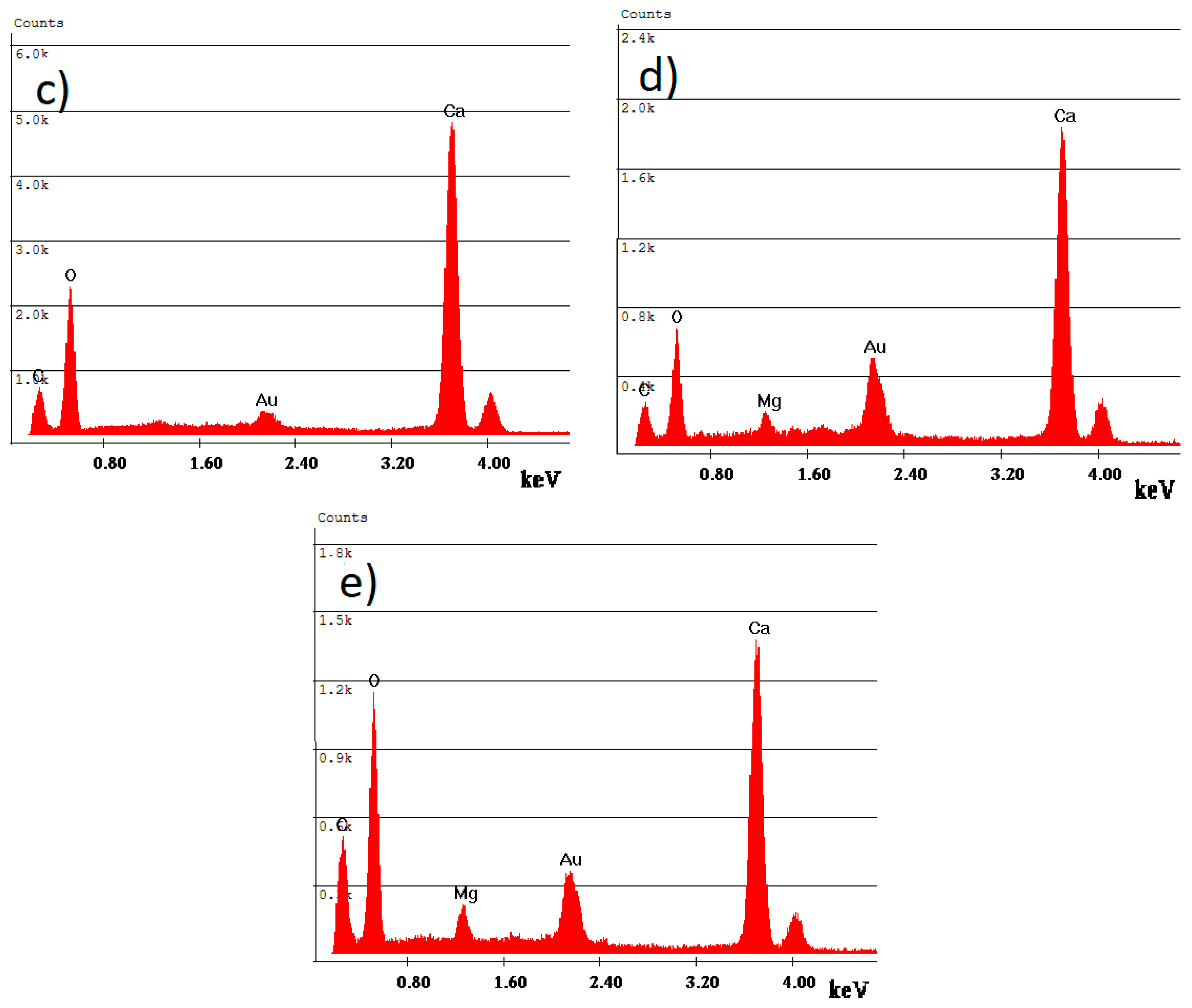
Energy-dispersive Spectrometry (EDS) was also performed to find the elements that were present in the samples. EDS allows a punctual measurement of elemental composition, thus this characterization cannot be directly extended over the entire sample. Nevertheless, important information on the difference in composition can be obtained by means of this analysis. EDS analyses of the fine fraction of each sample are reported in Figure 5. The common feature among all samples is that four main elemental peaks can be identified, which are represented by the elements calcium (Ca), oxygen (O), carbon (C), and gold (Au). The peak relating to carbon (C), being of limited intensity, is probably due to the membrane used as a support, which is of organic material. The peak relating to gold is due to sample conditioning, so it is not contained in the sample itself. The ratio of the calcium and oxygen peaks confirms that the fine powder could be composed of calcium hydroxide. In Sample 4 and Sample 5, magnesium (Mg) was also found. Higher carbon content was found in Sample 5 with respect to other samples.

3.2. Sorption Tests

Sorption tests were carried out at 25 °C following the methodology described in Section 2.1. Starting from the concentration of chloride sampled from the absorber (Cd) and applying the chlorides mass balance described by Equations (8)–(10), the inlet mass Ma, the average mass retained by the sample Mb, the mass upstream of the absorber Mc and the emitted mass Me were calculated. The chlorides mass adsorbed by the samples Mb, averaged at the different time steps, is reported in Table 3. The results of chlorides mass adsorbed in time by each sample (excluding outliers) are reported in Figure 6. Single test results were interpolated by mean of a linear fit. A linear fit was considered since the mass of the sorbent is in excess with respect to the adsorbate. Interpolation coefficients and statistics are reported in Table 4. The comparison of all samples is reported in Figure 7.
It is observed that sample C1 shows the highest mean sorption capacity (3.59 mg/g after 30 min). Sample C4 shows the lowest mean sorption capacity (2.98 mg/g after 30 min). Samples C2 and C3 also show lower sorption capacity than samples C1 and C5. The difference between samples is minimum at 5–10 min and increases with time. After 30 min, the sorption capacity of samples C2 and C4 is around 20% lower than that of C1.
Considering the tests on the individual samples separately, a difference in the variability of the results obtained is observed, as shown in Table 4. Samples C1 and C5 show a high repeatability of the tests, demonstrated by the high R2 values and low RMSE values. In contrast, samples C2 and C3 show a higher variability of results under the same conditions (R2 are lower and RMSE higher for these samples). The nature of this behaviour is not yet clear; the possible reasons could be connected to the heterogeneous size distribution and possible particle agglomeration effects.

4. Discussion

This study proposed the characterisation and comparison of different hydrated lime samples for the adsorption of a mixture containing HCl at a concentration of 548 ppm. For the characterisation, SEM measurements were conducted with a qualitative assessment of the appearance and composition of the various samples. The comparison between the samples was conducted by evaluating the sorption capacity using a specifically constructed experimental apparatus. The system was designed with the aim of simulating the contact conditions that occur in a dry inline injection system, specifically when a layer of sorbent is deposited on the surface of a bag filter.
The characterisation shows that the samples have a different appearance which indicates different particle size distributions. Samples C1 and C5 show a more uniform composition, with particle size in the order of 1–10 µm. Samples C2 and C3 are composed of larger and finer particles with respect to C1 and C5. Sample C4 is entirely composed of fine particles, that tend to agglomerate in clusters. The EDS analysis shows a very similar composition between the samples; the only difference is that Mg is detected for two samples (C4 and C5). Sorption tests show a marked difference (up to 20%) between the samples.
The different adsorption capacity between the samples is attributable to differences in the physical conformation of the samples, rather than differences in chemical composition. Based on the observations made, the specific surface area seems to be the primary driver of the removal efficiency. It is well known that a higher specific surface area of solid sorbents corresponds to a higher adsorption capacity, so it is to be assumed that sample C1 has a higher specific surface area than the others. This would have to be confirmed by BET analyses, which were not performed in this study. On the other hand, it was also observed that sample C4, characterised by a finer grain size, showed a lower adsorption capacity. This assumption, which should be confirmed, is attributable to agglomeration phenomena in the sample, which was highlighted by SEM analyses. It is known that calcium hydroxide aggregates and agglomerates, but it is not clearly known how and to what extent. Short-range van der Waals forces keep the particles attached to each other once the agglomeration has taken place [24]. Such phenomena may limit instead of increasing the adsorption sites available on the particles. Similar behaviour of fine-size sorbents was observed by Nethe and Uwe [16], who showed that some sorbent materials with a very fine particle size, although showing high values of a specific area, exhibited a lower adsorbing capacity than a less fine and more uniform material. Low sorbent conversion, which negatively affects process economics, in perspective, may possibly be improved by design and operating measures aimed at reducing product layer resistance [8]. This possibility should be verified in future studies in which particle aggregation is analysed together with sorption capacity. Complementary analyses like X-ray diffractometry (XRD), BET, and thermo-gravimetry will be performed.
Regarding the comparison of the absorption capacity found in the present study, it should be noted that the values resulting from these tests refer to a simplified small-scale process created for the purpose of a comparative evaluation between the samples. These values are therefore not representative of the conditions that can occur in a full-scale plant, and are not comparable with real data from systems in operation. Also, it is difficult to compare the values found with existing studies, for two reasons. The first is that the configuration of the present experimental apparatus is different from other previously presented lab-scale devices, so the comparison only makes sense in relative terms. The second reason is that previous studies have usually compared modifications of the same base product, in most cases involving the use of additives or chemical modifications. Similar results to the present study were reported by Micoli et al. (2013; [25]), who studied Na-based sorbents. They found that modified activated carbon with NaOH and Na2CO3 yielded an adsorption capacity of 11.9 mg/g, which was seven times that of unmodified AC. In most other studies, the comparison is reported in terms of the chloride removal capacity of the system. In this study, the chloride removal efficiency by the system ranged from 80% (C2, worse sorbent) to 99% (C1, best sorbent). These high values were partly due to the high contact time between gas and sorbent (around 60 s). Tan et al. (2020; [26]) demonstrated that at the reaction temperature range of 260–350 °C, the removal of SO2 and HCl by Ca(OH)2 was less than that by NaHCO3, and the dechlorination efficiency could reach more than 90%. In the review study of Wang et al. (2023; [27]), depending on process conditions and sorbents used, the HCl removal efficiency reported is between 24% and 97%.
The high dechlorination capacity found in this study was also achieved due to the high dosage of sorbent, in abundant excess of stoichiometric. This is because reagent consumption was not one of the objectives of the present study. Thinking therefore of a scaled application of the proposed model, on the one hand, there would be a strong reduction in chloride output, such that it would fall within the parameters required by the regulations. The Italian regulations for WtE plants foresee a daily limit for HCl of 10 mg Nm−3. On the other hand, however, a considerable production of residues would produce high disposal costs.

5. Conclusions

In this study, it was observed that a different hydrated lime conformation, especially in terms of particle size distribution, corresponds to a different absorption capacity of the material. According to the tests performed, it would appear that a more uniform distribution of a size in the order of a few µm would favour a higher chlorides sorption by the material. On the other hand, finer particles of the order of 0.1 µm could give rise to aggregation phenomena that could adversely affect sorption. This is in contrast with previous findings, showing that the diffusion resistance of HCl through the product layer is decreased by smaller particles. It is therefore necessary to further study the characterisation of the sorbent materials by means of analyses of particle size distribution, specific area and qualitative-quantitative chemical composition. The same tests should then be repeated at higher operating temperatures, similar to those commonly used in this type of process (130–150 °C). Furthermore, many factors in real operating conditions, such as process conditions or the co-presence of other substances and dust in the flue gas, shall be investigated.

Author Contributions

Conceptualization, M.R. and M.Z.; methodology, M.R., B.R. and M.Z.; software, M.R., E.M., G.Z. and M.Z.; validation, M.R., B.R., D.P. and M.Z.; formal analysis, M.R., E.M., A.C., G.Z. and B.R.; investigation, M.R., E.M., B.R., D.P. and M.Z.; resources, M.R., A.C., G.Z., B.R., D.P. and M.Z.; data curation, M.R., E.M. and G.Z.; writing—original draft preparation, M.R. and E.M.; writing—review and editing, M.R., E.M., B.R., D.P. and M.Z.; visualization, M.R., E.M., G.Z., B.R., D.P. and M.Z.; supervision, M.R., G.Z., B.R. and M.Z.; project administration, M.R. and M.Z.; funding acquisition, D.P. and M.Z. All authors have read and agreed to the published version of the manuscript.

Funding

This research received no external funding.

Institutional Review Board Statement

Not applicable.

Informed Consent Statement

Not applicable.

Data Availability Statement

The data presented in this study are available on request from the corresponding author.

Conflicts of Interest

The authors declare no conflict of interest.

References

  1. Cole-Hunter, T.; Johnston, F.H.; Marks, G.B.; Morawska, L.; Morgan, G.G.; Overs, M.; Porta-Cubas, A.; Cowie, C.T. The Health Impacts of Waste-to-Energy Emissions: A Systematic Review of the Literature. Environ. Res. Lett. 2020, 15, 123006. [Google Scholar] [CrossRef]
  2. Neuwahl, F.; Cusano, G.; Gomez Benavides, J.; Holbrook, S.; Roudier, S. Best Available Techniques (BAT) Reference Document for Waste Incineration; EUR 29971 EN; Publications Office of the European Union: Luxembourg, 2019. [Google Scholar]
  3. Dal Pozzo, A.; Antonioni, G.; Guglielmi, D.; Stramigioli, C.; Cozzani, V. Comparison of Alternative Flue Gas Dry Treatment Technologies in Waste-to-Energy Processes. Waste Manag. 2016, 51, 81–90. [Google Scholar] [CrossRef] [PubMed]
  4. Zheng, J.; Yu, L.; Ma, G.; Mi, H.; Jiao, Y. Residents’ Acceptance towards Waste-to-Energy Facilities: Formation, Diffusion and Policy Implications. J. Clean. Prod. 2021, 287, 125560. [Google Scholar] [CrossRef]
  5. Ravina, M.; Facelli, A.; Zanetti, M. Halocarbon Emissions from Hazardous Waste Landfills: Analysis of Sources and Risks. Atmosphere 2020, 11, 375. [Google Scholar] [CrossRef] [Green Version]
  6. Jurczyk, M.; Mikus, M.; Dziedzic, K. Flue gas cleaning in municipal Waste-To-Energy plants—Part II. Infrastrukt. I Ekol. Teren. Wiej./Infrastruct. Ecol. Rural Areas 2016, nr IV/2, 1309–1321. [Google Scholar] [CrossRef]
  7. Kumar, L.; Jana, S.K. Advances in Absorbents and Techniques Used in Wet and Dry FGD: A Critical Review. Rev. Chem. Eng. 2022, 38, 843–880. [Google Scholar] [CrossRef]
  8. Dal Pozzo, A.; Martello, G.; Cozzani, V. Sustainability Assessment of Furnace Versus In-Duct Sorbent Injection to Retrofit Waste-to-Energy Dry Flue Gas Treatment Lines. Chem. Eng. Trans. 2021, 86, 523–528. [Google Scholar] [CrossRef]
  9. Barba, D.; Brandani, F.; Capocelli, M.; Luberti, M.; Zizza, A. Process Analysis of an Industrial Waste-to-Energy Plant: Theory and Experiments. Process Saf. Environ. Prot. 2015, 96, 61–73. [Google Scholar] [CrossRef]
  10. Daoudi, M.; Walters, J.K. A Thermogravimetric Study of the Reaction of Hydrogen Chloride Gas with Calcined Limestone: Determination of Kinetic Parameters. Chem. Eng. J. 1991, 47, 1–9. [Google Scholar] [CrossRef]
  11. Duo, W.; Kirkby, N.F.; Seville, J.P.K.; Clift, R. Alteration with Reaction Progress of the Rate Limiting Step for Solid-Gas Reactions of Ca-Compounds with HCl. Chem. Eng. Sci. 1995, 50, 2017–2027. [Google Scholar] [CrossRef]
  12. Verdone, N.; De Filippis, P. Reaction Kinetics of Hydrogen Chloride with Sodium Carbonate. Chem. Eng. Sci. 2006, 61, 7487–7496. [Google Scholar] [CrossRef]
  13. Koech, L.; Rutto, H.; Lerotholi, L.; Everson, R.C.; Neomagus, H.; Branken, D.; Moganelwa, A. Spray Drying Absorption for Desulphurization: A Review of Recent Developments. Clean Technol. Environ. Policy 2021, 23, 1665–1686. [Google Scholar] [CrossRef]
  14. Bodénan, F.; Deniard, P. Characterization of Flue Gas Cleaning Residues from European Solid Waste Incinerators: Assessment of Various Ca-Based Sorbent Processes. Chemosphere 2003, 51, 335–347. [Google Scholar] [CrossRef] [PubMed]
  15. Kameda, T.; Tochinai, M.; Kumagai, S.; Yoshioka, T. Treatment of HCl Gas by Cyclic Use of Mg–Al Layered Double Hydroxide Intercalated with CO32−. Atmos. Pollut. Res. 2020, 11, 290–295. [Google Scholar] [CrossRef]
  16. Nethe, L.; Uwe, S. Special Lime with High Reactivity for the Absorption of Acid Gas Constituents. ZKG Int. 2008, 61, 1–11. [Google Scholar]
  17. Borgwarth, R.H.; Bruce, K.R.; Blake, J. EPA Experimental Studies of the Mechanism of Sulphur Capture by Limestone. In Proceedings of the First Joint Symposium on Dry SO2 and Simultaneous SO2/NOx Control Technologies, San Diego, CA, USA, 13–16 November 1984; Report Number EPA600/9-85-020b. U.S. Environmental Protection Agency, Air and Energy Engineering Research Laboratory: Research Triangle Park, NC, USA, 1985. [Google Scholar]
  18. Pesce, C.; Pesce, G.L.; Molinari, M.; Richardson, A. Effects of Organic Additives on Calcium Hydroxide Crystallisation during Lime Slaking. Cem. Concr. Res. 2021, 139, 106254. [Google Scholar] [CrossRef]
  19. Liang, S.; Liu, S.; Fan, Z.; Zhang, W.; Guo, M.; Cheng, F.; Zhang, M. Enhanced HCl Removal from CO2-Rich Mixture Gases by CuOx/Na2CO3 Porous Sorbent at Low Temperature: Kinetics and Forecasting. Chem. Eng. J. 2020, 381, 122738. [Google Scholar] [CrossRef]
  20. Stein, J. The Influence of HCl on S Absorption in the Spray Dry Scrubbing Process. Chem. Eng. J. 2002, 86, 17–23. [Google Scholar] [CrossRef]
  21. Han, J.W.; Hassoli, N.; Lee, K.S.; Park, S.S.; Kim, K.D.; Kim, H.T.; Park, Y.O. Dry Scrubbing of Gaseous HCl and SO2 with Hydrated Lime in Entrained Mixing Reactor. Powder Technol. 2021, 393, 471–481. [Google Scholar] [CrossRef]
  22. Zhou, X.; Tang, W.; He, M.; Xiao, X.; Wang, T.; Cheng, S.; Zhang, L. Combined Removal of SO3 and HCl by Modified Ca(OH)2 from Coal-Fired Flue Gas. Sci. Total Environ. 2023, 857, 159466. [Google Scholar] [CrossRef]
  23. Chin, T.; Yan, R.; Liang, D.T.; Tay, J.H. Hydrated Lime Reaction with HCl under Simulated Flue Gas Conditions. Ind. Eng. Chem. Res. 2005, 44, 3742–3748. [Google Scholar] [CrossRef]
  24. Rodriguez-Navarro, C.; Ruiz-Agudo, E.; Ortega-Huertas, M.; Hansen, E. Nanostructure and Irreversible Colloidal Behavior of Ca(OH)2: Implications in Cultural Heritage Conservation. Langmuir 2005, 21, 10948–10957. [Google Scholar] [CrossRef] [PubMed]
  25. Micoli, L.; Bagnasco, G.; Turco, M. HCl Removal from Biogas for Feeding MCFCs: Adsorption on Microporous Materials. Int. J. Hydrogen Energy 2013, 38, 447–452. [Google Scholar] [CrossRef]
  26. Tan, Z.; Niu, G.; Qi, Q.; Zhou, M.; Wu, B.; Yao, W. Ultralow Emission of Dust, SOx, HCl, and NOx Using a Ceramic Catalytic Filter Tube. Energy Fuels 2020, 34, 4173–4182. [Google Scholar] [CrossRef]
  27. Wang, Y.; Su, W.; Chen, J.; Xing, Y.; Zhang, H.; Qian, D. A Review of Hydrogen Chloride Removal from Calcium- and Sodium-Based Sorbents. Environ. Sci. Pollut. Res. 2023, 30, 73116–73136. [Google Scholar] [CrossRef]
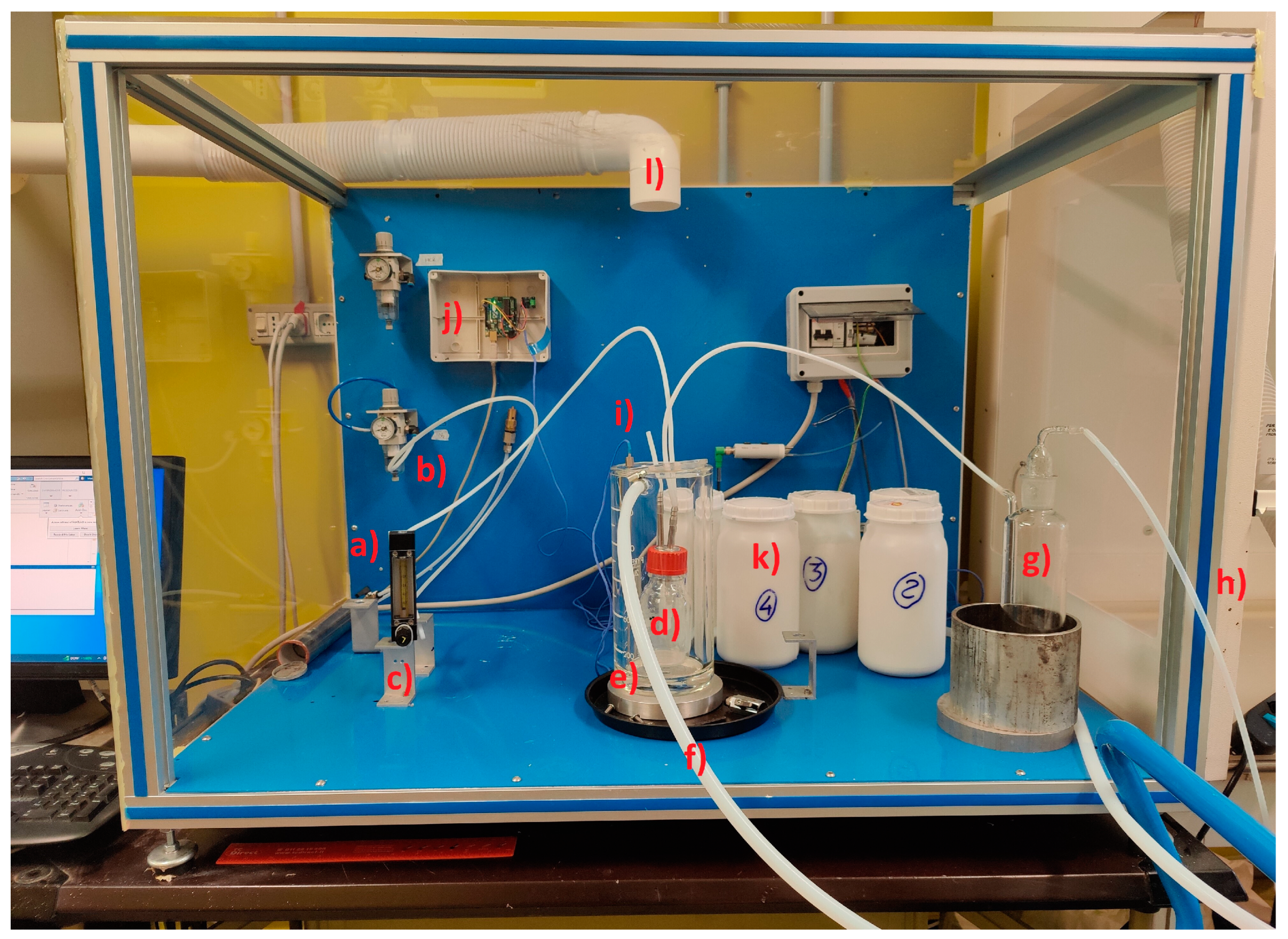
Figure 1. Photo of the experimental system: (a) HCl input line; (b) N2 input line; (c) Flowmeter; (d) Reactor, (e) jacketed beaker; (f) Thermo-conditioning circuit; (g) Water absorber; (h) vent line; (i) thermocouple; (j) Arduino device; (k) sorbent samples; (l) air extraction to ventilated hood.
Sustainability 15 10882 g001
Figure 2. Process scheme of the experimental installation. The HCl inlet flow and system pressure is regulated by a gate valve and flowmeter FC. Temperature is regulated by a closed loop thermal circuit controlled by the heat exchanger. Nitrogen gas line is used to flush the system.
Sustainability 15 10882 g002
Figure 3. Reference scheme for the calculation of chlorides mass balance: (a) total Cl inlet; (b) Cl adsorbed by the solid sorbent; (c) unreacted Cl exiting the reactor; (d) Cl absorbed by the water absorber; (e) residual Cl vented to the atmosphere.
Sustainability 15 10882 g003
Figure 4. Scanning electronic microscopy (SEM) pictures of Sample 1 (a), Sample 2 (b), Sample 3 (c), Sample 4 (d), and Sample 5 (e).
Sustainability 15 10882 g004aSustainability 15 10882 g004bSustainability 15 10882 g004c
Figure 5. SEM elemental analysis of Sample 1 (a), Sample 2 (b), Sample 3 (c), Sample 4 (d), and Sample 5 (e).
Sustainability 15 10882 g005aSustainability 15 10882 g005b
Figure 6. Adsorbed Cl mass over time of Sample 1 (a), Sample 2 (b), Sample 3 (c), Sample 4 (d), and Sample 5 (e).
Sustainability 15 10882 g006
Figure 7. Adsorbed Cl mass over time of all samples.
Sustainability 15 10882 g007
Table 1. Acid flue gas abatement technologies (adapted from [7]).
TechnologyPrincipleAdvantagesDisadvantages
Boiler/Inline injection of sorbent (or duct sorbent injection, DSI)A dry sorbent powder is dispersed by injecting it into the effluent gas stream (or combustion chamber). The sorbent reacts with the acid gas to form a solid, which is subsequently removed with dust suppression systems.Simple technology; minimum amount of auxiliary equipment; low operating costsMajor consumption of sorbent; higher amount of residuals; possible dust pollution of heat exchange surfaces
Conditioned dry sorptionSeparation of the pollutants is ameliorated by a hydrate shell which is formed around the lime particles and results from the H2O contained in the flue gas. The separation is governed by the dissolution rate of the pollutants in aqueous solution.Higher efficiency than no conditioned dry sorptionFlue gas must be conditioned to achieve higher relative humidity
Semi-dry scrubbingA spray dryer is used to inject a suspension of lime and water (lime slurry) into the flue gas stream. When the suspension is injected into the flue gas stream, the water component evaporates and only the solid lime particles remain in the flue gas.50% less water consumption than wet methods; dry residualsWorse use of sorbent in comp. to wet methods; Higher investment costs comp. to dry method
Wet scrubbingMakes use of a liquid such as water or an aqueous solution capable of absorbing the acidic compounds present in the gaseous effluent.Low consumption of sorbents; low sensitivity to fluctuation in flowsHigher complexity; higher corrosion; drop in flue gas temperature; large area needed
Flue gas desulphurization (FGD) with seawaterWet non-regenerative type that makes use of the natural alkalinity of seawater to absorb the acidic contaminants present in the gaseous effluent.No waste is formed; no reagents or additional chemicals; lower capital and operating costs.Low efficiency; wet residues.
Table 2. Sorption reactions.
Calcium Hydroxide Sodium Bicarbonate
Ca(OH)2 ⇄ Ca2+ + 2OH
HCl → H+ + Cl
Ca(OH)2 + 2HCl → CaCl2 + 2H2O
(1)2NaHCO3 → 2Na+ + HCO3
HCO3 ⇄ CO32− + 2H+ ⇄ CO2 + H2O
2NaHCO3 → Na2CO3 + CO2 + H2O
(4)
Ca(OH)2 ⇄ Ca2+ + 2OH
SO2 + 2OH → SO42− + 2H+
Ca(OH)2 + SO2 + ½O2 → CaSO4 + H2O
(2)Na2CO3 → 2Na+ + CO32−
HCl → H+ + Cl
CO32− + 2H+ ⇄ CO2 + H2O
Na2CO3 + 2HCl → 2NaCl + CO2 + H2O
(5)
Ca(OH)2 ⇄ Ca2+ + 2OH
CO2 + OH → HCO3 ⇄ CO32− + H+
Ca(OH)2 + CO2 → CaCO3 + H2O
(3)Na2CO3 → 2Na+ + CO32−
SO2 + 2OH → SO42− + 2H+
Na2CO3 + SO2 ½O2 → Na2SO4 + CO2
(6)
Table 3. Calculated mass of chlorides adsorbed by the solid sample (Mb, mean of all tests).
SampleCl Adsorbed (mg/g)
5 min10 min20 min30 min
C10.64661.26782.42353.5965
C20.63851.20462.18512.8956
C30.65891.29892.47373.1213
C40.6231.19602.1812.9888
C50.63091.20982.20723.4954
Table 4. Interpolation coefficients and statistics.
SampleLinear Fit y = p1x + p2
p1p2R2Root Mean Squared Error (RMSE)
C10.11760.072680.9970.048
C20.090530.27270.8760.312
C30.098020.30680.9420.236
C40.097180.18730.9810.113
C50.11210.057950.9930.085
Disclaimer/Publisher’s Note: The statements, opinions and data contained in all publications are solely those of the individual author(s) and contributor(s) and not of MDPI and/or the editor(s). MDPI and/or the editor(s) disclaim responsibility for any injury to people or property resulting from any ideas, methods, instructions or products referred to in the content.