Review

A Review on the Modelling Techniques of Liquid Storage Tanks Considering Fluid–Structure–Soil Interaction Effects with a Focus on the Mitigation of Seismic Effects through Base Isolation Techniques

Department of Civil Engineering, Manipal Institute of Technology, Manipal Academy of Higher Education, Manipal 576104, India
*
Author to whom correspondence should be addressed.
Sustainability 2023, 15(14), 11040; https://doi.org/10.3390/su151411040
Submission received: 29 May 2023 / Revised: 1 July 2023 / Accepted: 3 July 2023 / Published: 14 July 2023
(This article belongs to the Special Issue Earthquake Engineering Technology and Its Application)

Abstract

:
Globally, tanks play a major part in the provision of access to clean drinking water to the human population. Beyond aiding in the supply of fresh water, tanks are also essential for ensuring good sanitary conditions for people and for livestock. Many countries have realized that a robust water supply and a robust sanitation infrastructure are necessary for sustainable growth. Therefore, there is large demand for the construction of storage tanks. Further, liquid storage tanks are crucial structures which must continue to be operational even after a catastrophic natural event, such as an earthquake, to support rehabilitation efforts. From an engineering point of view, the various forces acting on the tanks and the behaviour of the tanks under various loads are important issues which need to be addressed for a safe design. Analyses of the tanks are challenging due to the interaction between the fluid and tank wall. Thus, researchers have conducted several investigations to understand the performance of storage tanks subjected to earthquakes by considering this interaction. This paper discusses the historical development of various modelling techniques of storage tanks. The interaction with the soil also influences the behaviour of the tanks, and hence, in this paper, various modelling approaches for soil structure interaction are also reviewed. Further, a brief history of various systems of base isolation and modelling approaches of base-isolated structures are also discussed in this article.

1. Introduction

Liquid storage tanks play a crucial role in day-to-day activities, as they are used for storing not only essential supplies such as water and oil but also to safely store hazardous chemicals. For the sustainable development of any country, it is necessary to provide access to fresh water. For this, a vast network of storage tanks is essential. Additionally, any major sanitary work involves the use of storage containers to temporarily store the sewage water before it is sent for further treatment. Storage tanks cater to the massive water demand from the construction industry and are thus essential for any country to build a robust infrastructure. One of the sustainable development goals (Goal 6) as set by the United Nations, is to provide access to drinking water, sanitization, and hygiene globally by 2030 [1]. This target indicates that there will be a huge demand for storage tanks in the near future. As many countries are working towards this goal, they are building massive infrastructure which involves a vast network of tanks. Due to industrialization, massive amounts of hazardous chemicals are stored in storage containers. Be it a water storage tank or hazardous material storage container, any damage to these structures during a natural hazard, such as an earthquake, can lead to disastrous consequences. Thus, it is essential that these structures are resilient to natural disasters such as earthquakes, cyclones and tsunamis to ensure the sustainable growth of any country. Thus, engineers must have the knowledge and tools to design long-lasting tanks capable of resisting natural disasters.
Further, understanding the structural behaviour of the tanks helps the designer to achieve safety and economy in their design, which ensures sustainability in the long run. In the event of a natural disaster, there is always a risk of damage to tanks. Any such failure of a water tank may hamper the rehabilitation work as a continuous water supply is necessary to manage the possible subsequent fires and also to avoid any disease outbreak post disaster. Further, natural disasters can lead to the spillage of combustible products from the damaged tanks and may lead to fire hazards, potentially harming the environment [2]. The tanks are prone to earthquakes mainly due to their large mass. In the event of strong ground motions, and unlike other structures, such as buildings and bridges, tanks are also subjected to large hydrodynamic forces, making them critical structures, vulnerable to earthquake-induced vibrations. A lack of careful evaluation of these forces can lead to inadequate design, resulting in failure during strong ground motion. Several storage tanks have failed in the past due to strong earthquakes [3]. Over 30 tanks failed during the Turkey earthquake in 1999 [4], and 167 failed during the 2011 Tohoku earthquake [5]. Depending on the overturning moment and fluid pressure variation activated through seismic motion, the tank may undergo elastic–plastic or elastic buckling failure [6].
In structures such as buildings, interaction typically happens with the connected solid elements, such as between frames and infills or between columns and slabs, which are solid-to-solid interactions. However, tanks are unique in this sense; in tanks, the interaction happens between wall structure and liquid, which is a solid and fluid interaction. This fluid–structure interaction (FSI) is fairly complicated to model due to the interaction between two highly incompatible materials. Before the 1960′s, and owing to the difficulty involved with this modelling, tank walls were idealized as rigid and the effects of the interaction between the liquid and the wall of the tank were ignored [7]. However, the failure of such tanks during earthquakes between 1960 and 1970 showed that the storage tanks have much complex behaviour during ground motion, and that the flexibility of the tank cannot be ignored [2]. Thus, researchers nowadays consider the FSI effects in the modelling for a realistic analysis of tanks. Due to the evolution of various numerical techniques and advancements in computer technology, many researchers have been able to develop new modelling techniques for tanks, such as boundary element methods (BEM) and finite element methods (FEM), to investigate the response of fluid-filled storage containers subjected to seismic excitations [8].
Usually, the foundations of tanks are idealized as rigid units in conventional analysis. However, being made of different materials, there will be an interaction effect between tank and supporting soil on the tank behaviour. This soil–structure interaction (SSI) has been investigated by numerous researchers and it was found that ignoring the SSI effects by assuming the foundation to be rigid leads to unrealistic results [9,10,11,12]. It has been found that the soil stiffness significantly influences the behaviour of tanks subjected to ground motion [13]. Thus, when the SSI effect is considered, the tank’s overall stiffness changes, which considerably alters its time period. The realistic analysis of a tank therefore depends on both FSI and SSI modelling and therefore these effects need to be considered during the analysis to accurately represent tank behaviour.
Due to the high significance attached to the fluid tanks, many researchers have focused on developing techniques to make the tanks earthquake resistant. Base isolation is one such promising and widely used technique for aseismic design [14]. In a base isolation system, a layer of relatively lesser stiffness is incorporated between the structure and the ground. This low-stiffness layer offsets the transfer of harmful frequencies to the tanks. To date, researchers have developed a wide variety of base isolation bearings which can be used as a standalone devices or can be used in a hybrid configuration with other types of earthquake resistant devices. A brief discussion on base isolation techniques is carried out later, in Section 4. Readers can refer to a number of review articles on various base isolation techniques and systems in [14,15,16,17,18,19,20,21].
Several review papers on the historical development of tank modelling techniques [14,22,23] are currently available. The scope of these papers is typically limited to either fixed-base tanks [22] or base-isolated tanks. This means there is a lack of review articles which address these different tank types together. Additionally, a specific and detailed discussion on the SSI effect, which is one of the major influencing factors on tank behaviour, is absent in these papers. Therefore, the authors of this paper felt the need to address the lack of a recent comprehensive review paper which collectively discusses the various aspects of modelling for both fixed and base-isolated tanks. In this regard, the developments in the various modelling techniques of fluid tanks, including the effects of FSI and SSI, are discussed in detail in the present paper. Further, Section 4.3 of this article is dedicated to discussions on the modelling of base-isolated tanks. Thus, this article aims to bridge the gap between discussions on the advancements in the area of fixed tanks and base-isolated tanks by collectively addressing the developments in these areas. The main contribution of this article would be to review various aspects of tank modelling, including the effects of SSI and FSI, with an emphasis on base isolation techniques used for the seismic resistance of tanks.
Some researchers have reported that elevated tanks are more vulnerable when compared with tanks that are supported on the ground. This is mainly due to the larger time period of the elevated tanks when compared with the ground-supported tanks. This higher time period is attributed to the flexibility provided by the tank staging. Though the discussions in this article are directed towards ground-rested tanks, the modelling concepts are also applicable to elevated tanks. The main distinction between the analysis of ground-rested and elevated tanks is the additional modelling requirements of tank staging. Therefore, very limited discussion has been carried out regarding elevated tanks.

2. Modelling Techniques for Storage Tanks Considering FSI Effects

For studies before the 1960s, researchers generally used a simplified technique developed by Westergaard [24] for tank analysis. This technique was initially developed to evaluate the fluid pressure on rigid dams subjected to harmonic excitation and later adapted for tank analysis [25]. Since then, researchers have proposed various modelling techniques exclusive to tanks and these are discussed in the subsequent sections.

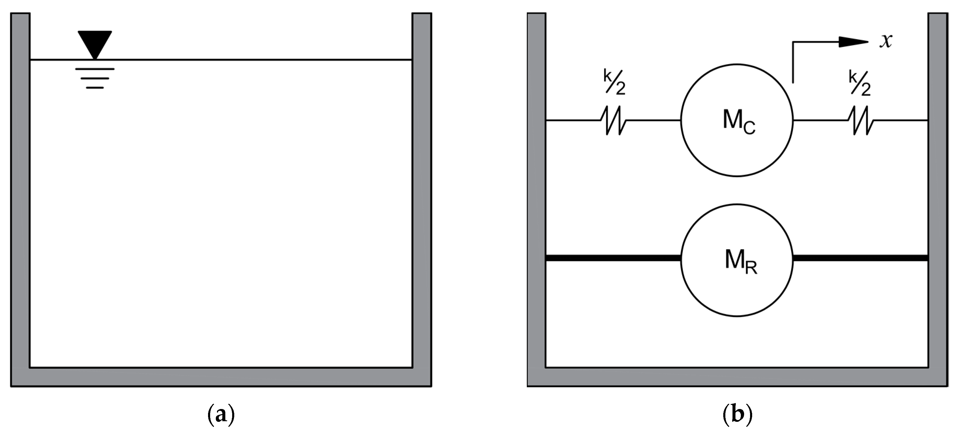
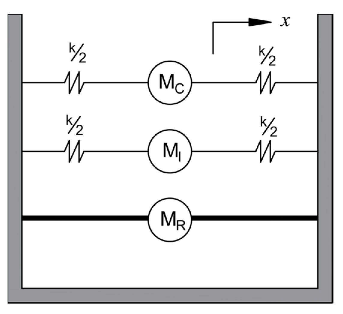
2.1. Equivalent Mechanical Models

The equivalent mechanical model was initially proposed by Housner [7,26] for analysing ground supported and elevated tanks filled with fluid. In this model, the tank walls are idealized as rigid units. The equivalent mechanical model was derived from the models of Biot [27] and Housner et al. [28], which were used earlier for a response spectrum analysis. As shown in Figure 1, in this model, two masses are considered, one for the convective mass (MC) and the other for the non-sloshing part (MR). The convective mass denotes the sloshing part of the fluid, and the rigid mass represents the non-sloshing part. These fluid masses MC and MR are responsible for the forces developed on the tank walls. The expressions to calculate these masses and stiffness k for a cylindrical tank with radius R and depth of water h are as follows:
M R = M t a n h 1.7 R h 1.7 R h
M C = 0.6 M t a n h 1.8 R h 1.8 R h
k = 5.4 M C 2 M g h R 2
where M is the total fluid mass. The heights of these masses hR and hC can be obtained by using the expressions as follows:
h R = 3 8 h 1 + 1.33 M M C R h 2 1
h C = h 1 0.185 M M C R h 2 1.12 R h M R 3 M C h 2 1
Similarly, the expressions related to rectangular tanks of width 2L are as follows:
M R = M t a n h 1.7 L h 1.7 L h
M C = 0.83   M t a n h 1.6 L h 1.6 L h
k = 3 M C 2 M g h L 2
h R = 3 8 h 1 + 1.33 M M C L h 2 1
h C = h 1 1 3 M M C L h 2 1.26 L h 0.28 M L M C h 2 1
In addition, the author suggested that this approach is applicable to an elevated tank as well.
The equivalent model proposed by Housner [7,26] was widely used for some time and even incorporated in the codes and standards of practice of some countries [29,30]. However, many storage tanks which were designed as per the codal provisions of the 1960’s failed during earthquakes. These failures indicated that the codal provisions which were developed based on the assumption that tank walls are rigid could not realistically represent the forces on the tanks. Thus, the researcher Veletsos [31] proposed a tank model including the flexibility aspect of tank walls. In this study, it is only the effect of impulsive forces that is evaluated with the assumption of single degree of freedom (SDOF) behaviour of a tank–fluid system. The hydrodynamic forces are calculated using the method proposed by Chopra [32,33]. The equation of motion considered by Veletsos [31] is as follows:
m I , S * + m I , L * w ¨ + c * w ˙ + k * w = m R , S * + m R , L * u ¨ t
where, m*, k* and c* represent the effective mass, stiffness and damping coefficients of the system. The subscripts R and I represent the rigid and impulsive components, respectively, and the subscripts S and L indicate the contribution of masses from structure and liquid, respectively. The responses of the tank in terms of base moment and base shear are calculated. The model developed by this approach shows a significant effect on the seismic response of tanks compared with the seismic response of tanks modelled by assuming rigid tank walls. However, in this study, the convective component of the response is neglected based on the assumption that this response depends on the sloshing period, which is much higher than the tank period. Later, Haroun and Housner [34,35] presented another model in which the fluid mass is represented with three lumped masses. These masses comprise three parts representing the rigid (MR), convective (MC), and impulsive (MI) masses of the fluid. These masses are calculated from the numerical study conducted by Haroun [2]. Figure 2 shows the mechanical model as proposed by the researchers Haroun and Housner [34,35]. Several researchers later used this model as a reference in their studies and validated their results through experimental investigations [36,37,38,39,40].
Malhotra et al. [41] proposed another model to evaluate the tank’s response using sloshing and impulsive masses to model the fluid mass. As shown in Figure 3, a dashpot system is used in the model to represent the damping effects. The convective and impulsive natural period for a system with tank height H and radius r is calculated using the expression as follows:
T C = C C r
T I = C I H ρ t r × E
Here, t is the tank wall thickness, ρ is the liquid mass density, and E is the modulus of elasticity of the tank material. CI and CC are impulsive and convective coefficients which depend on the aspect ratio of the tank. These coefficients are derived from the study conducted by Veletsos and co-workers [42,43,44]. Interested readers may refer to the table given by Malhotra et al. [41] to obtain the values of CI and CR and other parameters required for the seismic design of storage tanks. The model has been found to be efficient, especially for the analysis of cylindrical containers. The design procedure is also incorporated in the European code of practice [41].
The simplified models discussed in this section are useful in studying the global aspects of tank response, such as base moment or base shear. However, numerical methods are recommended to conduct a detailed analysis of tanks that include the response even at the local level [45]. The following section is dedicated to the discussion of different numerical methods for tank modelling and analysis.

2.2. Direct Modelling Approaches

The advancement in computer technologies has enabled researchers to develop various numerical approaches, such as FEM and BEM, which can be used for the direct modelling of tanks. Unlike the mechanical models, which are limited only to tanks with regular geometries, numerical methods can also be used for tanks of arbitrary geometries [46]. The researcher Edwards [8] proposed one of the earlier numerical techniques to study a short (aspect ratio of less than 1) cylindrical tank. For this study, Edwards [8] used a refined shell theory to evaluate the displacements and stresses in a tank. Several researchers used this approach later with minor modifications to study the various aspects of storage tanks [47,48,49].
The FEM-based methods used to solve FSI problems are classified as added mass [24], Lagrangian (displacement based), and Eulerian (pressure based) formulations [50]. In the added mass technique, a part of the fluid mass is added to the structure’s wall at the interface of the wall and fluid elements. This added mass (MA) moves along with the wall during the seismic vibrations. The equation of motion for tanks inclusive of added mass can be considered as follows:
M * u ¨ + C u ˙ + K u = M * u ¨ g
where, M* is a matrix representing the combination of tank mass (M) and added mass (MA). K and C are the stiffness and damping matrices of the tank, respectively. Additionally, u ¨ g in Equation (6) represents the ground acceleration. From Equation (6), it can be observed that part of the fluid mass is also added to the tank’s mass for the total mass calculation. However, only the tank walls are considered when calculating the damping matrix, ignoring the contribution of the fluid. The researchers found that this method leads to conservative results [51]; therefore, several investigators used this approach in their storage tank analysis [24,52,53,54,55,56]. Because the damping effect is ignored, this method generally leads to higher force calculation. Though conservative, the forces calculated are not realistic as the damping effect is a major aspect, one which significantly affects the tank behaviour under the action of earthquakes.
In the generalized Lagrangian method used earlier for the dams, the liquid is discretized as a solid element with a negligible shear modulus [57,58]. The general form of equation of motion applicable to this approach is as follows:
M u ¨ + C u ˙ + K u + f I + f 0 = 0
where fI and f0 are the interface forces between the tank wall and fluid. This method yields symmetric matrices, resulting in narrow bandwidth matrices during the analysis [59]. This reduction in bandwidth is one of the major benefits this method offers, as it significantly reduces the computational time when used in computers. Due to this benefit of reduced computational effort, many researchers later proposed different forms of finite elements to model a fluid suitable for the Lagrangian approach [51,60,61,62,63]. The Lagrangian formulation since then has been used by several researchers to study storage tanks [64,65,66]. Though the Lagrangian approach leads to the reduction of computational efforts, some researchers have suggested that it leads to less accurate results [67,68].
The generalized Eulerian approach is based on the pressure formulation method [69] in which the motion of a liquid is directed by the continuity relation and the Navier–Stokes equation [61]. The general form of the equation of motion used for this approach, which couples the tank–fluid system, is as follows:
K S 0 H u p + C 0 0 A u ˙ p ˙ + M 0 S T E u ¨ p ¨ = f t
where H, A, and E are matrices for the fluid domain, u and p are displacement and fluid pressure, respectively, f(t) is the external force on the system, and S is the interaction matrix for a tank–fluid system, and which can be obtained based on boundary conditions between them. Although this approach leads to an unsymmetrical matrix and subsequent increase in computational cost [70], the method has wide application due to the lesser number of variables when compared with the Lagrangian approach. Moreover, the method becomes computationally efficient when the compressibility effect of fluid is neglected [61]. Hence, several researchers favour the Eulerian approach when assessing the behaviour of storage containers [71,72,73].
Another approach to evaluate storage tank behaviour is with the use of BEM [74]. Unlike FEM where the entire fluid is discretised into different finite elements, in this approach the fluid is discretized only at the boundary using surface elements. This method is computationally efficient as it reduces the number of elements required considerably compared with completely FEM-based tank models. Moreover, BEM and FEM can be used together for a tank’s analysis, here the liquid can be modelled using BEM, and the tank walls are modelled using FEM, thus providing the benefits of both approaches. This advantage has prompted several researchers to use this method to solve the FSI problem in dams [75,76,77] and tanks [78,79,80,81,82]. The governing equation of motion for a coupled tank–fluid system based on FEM–BEM is as follows:
M o o M o c 0 M c o M c c + M c c A M c f A 0 M f c A M f f A u ¨ o u ¨ c ξ ¨ e + K o o K o c 0 K c o K c c 0 0 0 K f f u o u c ξ e = 0
where M and K are mass and stiffness matrices respectively, u indicates the horizontal motion, ξe indicates the sloshing vector, subscript ‘o’ indicates the degrees of freedom of the tank which is not in contact with fluid, subscript ‘c’ indicates the degrees of freedom of the tank which is in contact with fluid and MA denotes the added mass matrix of the fluid.

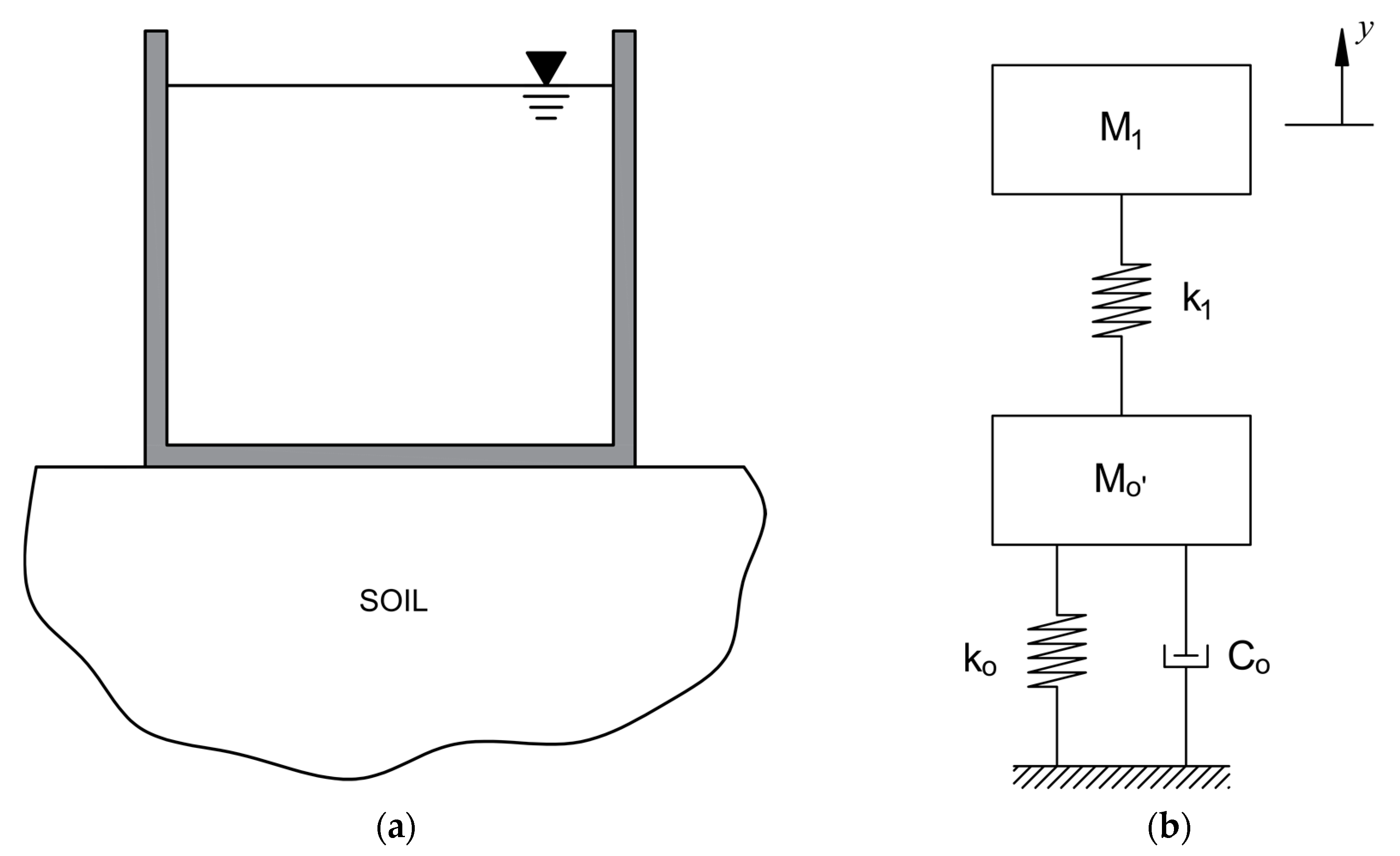
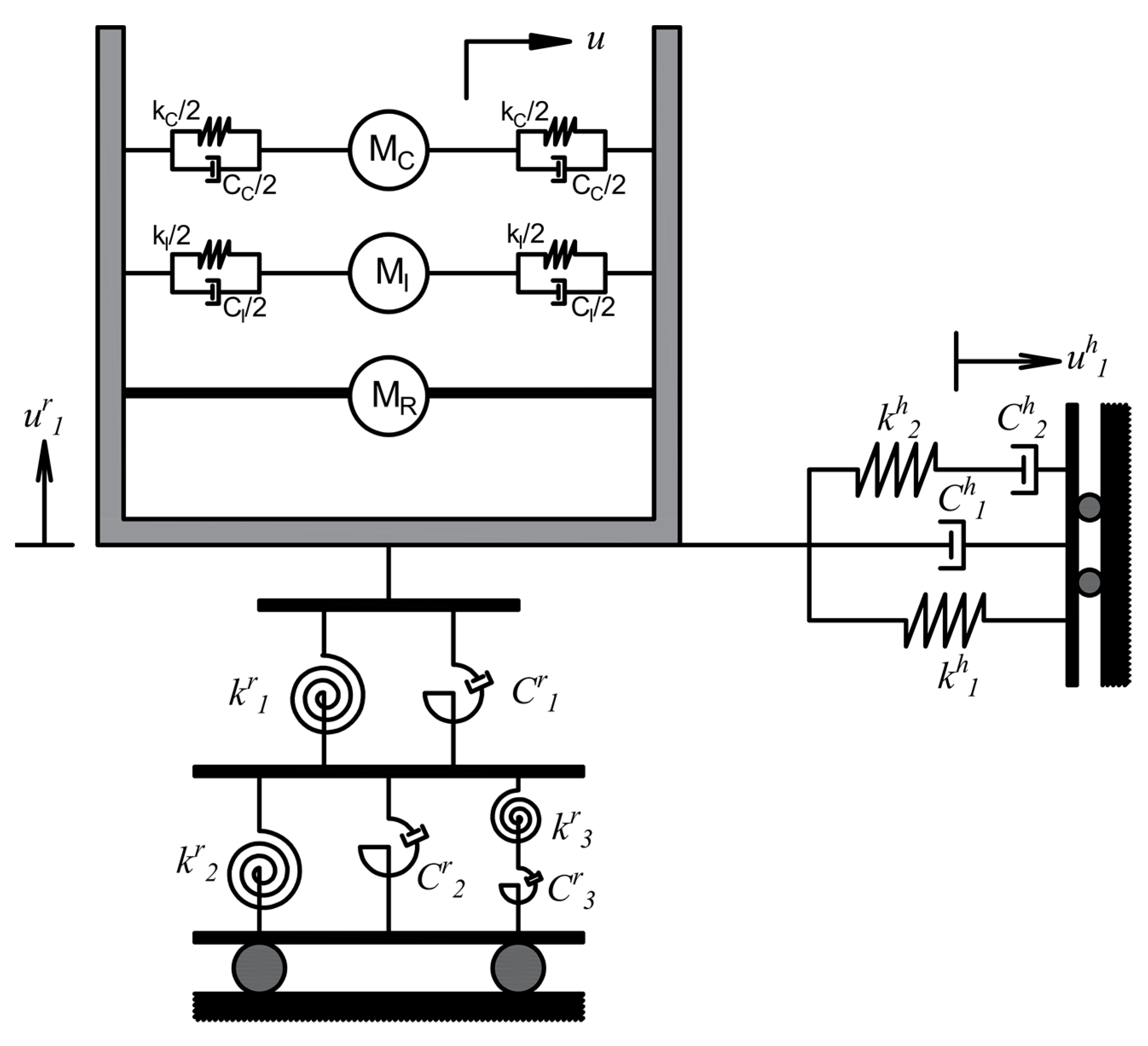
3. Modelling Approaches for Storage Tanks Considering Combined FSI and SSI Effects

In many of the earlier studies, the tanks resting on the ground were assumed to be supported by a rigid surface, and accordingly, the analyses were carried out by idealizing the tank foundation as fixed [43]. However, soil conditions significantly affect the behaviour of structures when subjected to ground vibrations, as the response of a structure varies with the stiffness of soil. The effect of support conditions on the response of a structure was first recognized by Martel [83], based on the observations of the failure of structures during many earthquakes in Japan [84]. Later, many researchers would go on to conduct numerical and experimental investigations on the SSI effect on the behaviour of building structures [11,85,86,87,88,89,90,91,92]. Since tanks are also supported on the ground, it is logical to assume the presence of interaction effects between tanks and the supporting soil. Therefore, for the analysis of tanks, both FSI and SSI effects need to be incorporated for a realistic analysis. The research carried out by Chopra et al. [93] represents one of the early attempts to address the combined effects of FSI and SSI on tank behaviour. These authors proposed a general technique to study the response of gravity dams considering the interaction effect between the water and dam wall. Further, several such investigations on gravity dams and bridges have been conducted by investigators considering the combined effects of FSI and SSI on dams [93,94,95,96,97,98,99]. Taking a cue from this research in the area of dams, Veletsos and Tang [100] proposed a simplified FSI–SSI combined model exclusively for tanks. As shown in Figure 4, the researchers used a two degree of freedom (2DOF) model in which the mass of the foundation, the tank, and the portion of the non-sloshing mass are represented together as M0′ and sloshing fluid mass as M1 for the investigation. In the model, the effect of SSI is considered by a spring and dashpot system. The governing differential equation considered by Veletsos and Tang [100] is as follows:
D 4 w z 4 + E h a 2 w + ρ h 2 w t 2 = p z , t
where D is the flexural rigidity of the tank wall and p(z,t) is the hydrodynamic wall pressure which is a function of the axial component of the coordinate system (z) for the tank and time (t), a is the tank radius, and h is the wall thickness. This model was later to be used by many researchers in their studies [101,102].
Although the method presented by Veletsos and Tang [100] was simple and easy to apply, for their study they considered only harmonic loading, and the effect of random vibration was not included. Seismic excitation belongs to the random vibration domain, and hence the response of the tanks to these vibrations is probabilistic in nature. Hence, Chatterjee and Basu [103] presented another method to estimate the SSI effect on the performance of a tank by applying random vibration theory. As shown in Figure 5, the tank and liquid are represented by the spring–mass dashpot system, and the foundation is modelled as a spring–mass system with mi as the impulsive mass of the fluid and mf as the foundation mass. These masses are connected with a spring of stiffness K and a viscous damper of coefficient C. The foundation mass is connected with a complex impedance function Kx. The governing equation of motion for the system considered is as follows:
m i x ¨ i t + x ¨ t + m f x ¨ t + K x x t x g t = 0
Here, double overdot represents the second derivative of displacement with respect to time, and xg is the ground motion. From the study, the authors concluded that the effect of SSI increases the response of tanks. Additionally, the SSI effect is found to be greater in slender tanks compared with broad tanks.
The researcher, Larkin [104] proposed a frequency domain approach to evaluate the seismic performance of storage tanks supported on the soil stratum. As shown in Figure 6, the system in the proposed model is assumed to have a single mass M with lateral stiffness of K and damping coefficient C. This model is capable of simulating both rocking and translational motions of the tanks subjected to ground motions. This study suggested that the SSI effect is prominent for slender tanks resting on soft soil. It is also shown in the study that the impulsive period of the tank increases with a decrease in soil stiffness.
Meng et al. [105] proposed a time domain approach to investigate the seismic behaviour of storage containers resting on elastic soil. As shown in Figure 7, a tank–liquid system is modelled using three masses—rigid, convective, and impulsive—to form a spring–mass system, as proposed by Haroun and Ellaithy [37], while the soil is modelled using a second-order lumped parameter model as proposed by Wu and Lee [106]. The governing equations of motion are obtained using kinetic energy T, potential energy V and the energy absorbed by dampers δW. These parameters are calculated as follows:
T = 1 2 M C u ˙ C + u ˙ R + H C u ˙ 1 r + u ˙ g 2 + 1 2 M I u ˙ I + u ˙ R + H I u ˙ 1 r + u ˙ g 2 + 1 2 M R + M B u ˙ R + H R u ˙ 1 r + u ˙ g 2 + 1 2 I R + I B u ˙ 1 r 2
V = 1 2 k C u C 2 + 1 2 k I u I 2 + 1 2 k 1 h u R 2 + 1 2 k 2 h u R u 1 h 2 + 1 2 k 1 r u 1 r u 2 r 2 + 1 2 k 2 r u 2 r 2 + 1 2 k 3 r u 2 r u 3 r 2
δ W = C C u ˙ C δ u C C I u ˙ I δ u I C 1 h u ˙ R δ u R C 2 h u ˙ 1 h δ u 1 h C 1 r u ˙ 1 r u ˙ 2 r δ u 1 r u 2 r C 2 r u ˙ 2 r δ u 2 r C 3 r u ˙ 3 r δ u 3 r
In these equations, the superscripts h and r represent the horizontal and rocking degrees of freedom, respectively. From this study it has been observed that the SSI has a negligible effect on the convective component of responses; however, the effect is prominent for impulsive responses.
Though the spring–mass model used by many investigators represents the effect of SSI effectively, some investigators realized that the simplified model tends to generate overly conservative results [107] and that a reasonable representation of the system can be obtained by using FEM [92]. In this regard, several researchers used FEM in their analysis of tanks [108,109,110,111]. Irrespective of the modelling approach used, it can be seen that the effect of SSI is prominent for tanks resting on soft soil.

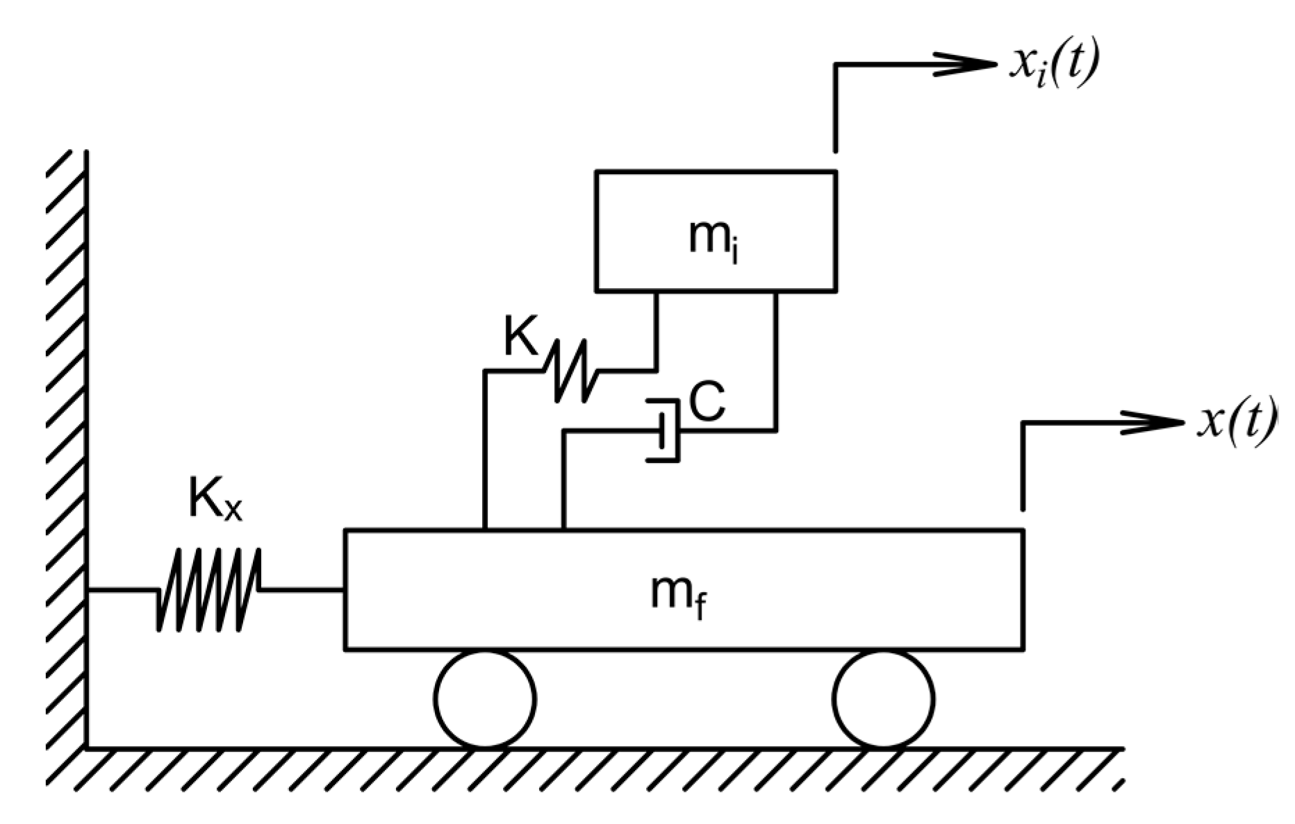
4. Base Isolation Techniques for Storage Tanks

Due to the high importance attached to storage tanks as discussed in Section 1, it is necessary to mitigate the harmful effects of ground vibrations on tanks. Several earthquake resistant techniques have been proposed by researchers for the building of structures such as bracing systems, viscous fluid dampers and base isolation bearings. Out of these systems, base isolation systems are now widely used around the world for earthquake-resistant buildings. Apart from buildings, base isolation systems can also be used in tanks to improve earthquake resistant capabilities. In this section, an overview of various types of isolation systems and modelling techniques of isolated structures is presented.

4.1. Types of Base Isolation Systems

The primary purpose of base isolators is to decrease the frequency of structures to a value lesser than that of earthquakes, avoiding the transfer of harmful vibrations to the structure. Base isolation bearings also provide a means to mitigate seismic energy, reducing the force transferred to the structure. The isolation systems are broadly categorized as elastomer-based bearings and friction bearings. The elastomer bearings are manufactured using natural rubber as a main ingredient. Due to their elastic property, the bearings provide the restoring mechanism by default. Friction isolators work by the principle of sliding friction or rolling friction. In sliding isolators, the restoring capacities are provided either by changing the sliding surface geometry or by connecting to external restoring mechanisms. The usage of natural rubber blocks as base isolators in a school in Skopje in 1969 is regarded as one of the earlier known applications of elastomeric bearings [112]. Due to the low vertical stiffness, these rubber blocks later bulged sideways due to lack of vertical stiffness. This issue was later resolved by increasing the vertical stiffness through the usage of steel plates embedded within the rubber blocks [17]. The damping capacity of elastomer isolators can be controlled by adding some fillers, resins or oils to the natural rubber. The hysteretic behaviour of a damper plays a significant role in seismic energy dissipation. To enhance their energy dissipation, some researchers proposed elastomer bearings with lead cores [113] known as lead rubber bearings (LRB). As shown in Figure 8a, the lead core is inserted at the centre of an elastomer bearing. The behaviour of LRB is nonlinear, accordingly the hysteresis loop is idealised as a bilinear curve as shown in Figure 8b. Due to this arrangement, a single damper can provide vertical load carrying capacity, as well as restoring and damping capacities, improving their value [114].
Sliding bearings are another class of isolation systems used to dissipate energy through friction. The simplest form of sliding bearing system is the pure friction (PF) system which can be achieved by a layer of sand, Teflon bearings, or rollers between the foundation and superstructure [112]. Some researchers have also proposed a combination of PF systems with elastomeric bearings known as the “Electricité de France” (EDF) system [115]. Another type of system called resilient-friction base isolator (RFBI) was presented by Mostaghel and Khodaverdian [116] and consists of layers of sliding metal plates with a rubber core. The sliding elements provides base isolation, and the rubber core provides restoring capabilities. In PF isolation systems large residual displacements are typically observed; thus, some authors have proposed elliptical rolling rods at the base to overcome this issue [117]. Similarly, to address the issue of a lack of restoring mechanism in PF systems, Zayas et al. [118] proposed a curved geometry known as a friction pendulum (FP) isolator. As shown in Figure 9a, the curved geometry of the isolator helps restore the structure resting on the bearing to its original position after ground motion. The hysteresis loop of the FP system is shown in Figure 9b. k represents the post elastic stiffness and keff represents the effective stiffness of the isolator. The FP system is an extensively studied system and is commonly used, mainly due to its simplicity and the relative ease of its manufacture. Though FP bearings are efficient in a wide range of earthquakes, they show large sliding displacements under earthquakes with pulse-like frequencies.
To address the drawback of FP bearings, researchers have proposed several solutions. Pranesh and Sinha [119] presented a bearing known as a variable frequency pendulum isolator (VFPI) that has a non-spherical (elliptical) surface. Due to the elliptical geometry, the frequency of the isolator varies along the sliding surface, avoiding the resonance issues which are observed in FP bearings. Another isolator system called the variable curvature friction pendulum system (VCFPS) was presented by Tsai et al. [120], wherein the radius of the curved surface is lengthened as the isolator displacement increases. The conical friction pendulum isolator (CFPI) is another system that has modified an FP bearing geometry [121]. Within a certain threshold region, the bearing behaves in a similar way to that of an FP bearing; however, beyond this threshold, the surface is flat and inclined. This isolator has shown a low residual displacement for near-fault earthquakes compared with FP. A further system was introduced by Krishnamoorthy [122], called a variable frequency and variable friction pendulum isolator (VFFPI), to solve the resonance issue in FP bearings. The shape of this isolator surface and its friction coefficients vary along a sliding surface. Due to the varied geometry the resonance issue is avoided in VFFPI. Further, the residual displacement of VFFPI has been found to be less than that of PF systems. Various additional isolation bearings with multiple sliding surfaces have been introduced in recent years. A detailed review of the advancements in isolation systems with sliding bearing can be seen in [19].

4.2. Base Isolated Tanks

The system of base isolation is effective not only for buildings and bridges but also for tanks. Several investigations have been conducted to assess the effectiveness of base isolation systems for tanks [123,124,125]. Studies conducted by the researcher Malhotra [126,127] on tanks isolated at base using elastomers show that the isolation scheme is effective when these tanks are subjected to the vertical component of ground motion. Similar investigations conducted later also found that the elastomer isolators are effective in reducing the seismic response of tanks [128,129,130,131,132,133,134,135,136]. In these investigations tanks were assumed to be full i.e., the liquid level in the tank remains fixed. However, in reality the weight of a tank varies due to the fluctuating liquid levels; as a result, the effectiveness of an elastomeric system varies, adversely affecting the reliability of isolation systems. Sliding isolation bearings, such as FP bearings, however, do not have the pitfalls of the elastomers as these bearings maintain a constant isolation period which is independent of a structure’s weight. Thus, the liquid level in storage tanks does not affect the effectiveness of such bearings. In this regard, Wang et al. [137] proposed a procedure to evaluate the behaviour of the isolated tanks by considering FP bearings. Though the performance of FPS bearings is not affected by the level of water in the tank, due to their fixed isolation period, they do not perform satisfactorily under near-fault earthquakes as discussed in Section 4.1. Thus, in some studies, tanks isolated using a variable friction pendulum system (VFPS) were considered to investigate their performance under various near-fault ground motions [138,139]. It was concluded that the VFPS can be used effectively to control the response of fluid-filled containers under near-fault earthquakes. Similarly, many other researchers have considered different types of sliding isolation systems based on the modified geometry of FP bearings to evaluate the effect of base isolators in controlling the response of tanks subjected to ground motions [140,141,142,143,144,145,146,147]. In all of these studies, investigators found that isolators had been effective in regulating the storage tank responses.
Numerical methods have also been used recently to evaluate the behaviour of isolated tanks [81,82]. In these studies, the fluid and isolation system effects are modelled by coupling boundary and finite elements. Comparative studies conducted by Christovasilis and Whittaker [148] and Kalantari et al. [149], between FEM models and simplified mechanical models for isolated tanks, suggest that the simplified models could only be used for preliminary analysis and design but that FEM modelling is a better choice for detailed study. Krishnamoorthy [150] proposed a procedure for analysing a tank resting on FP bearings by using FEM. As shown in Figure 10 the fluid is discretized into four noded elements with one pressure degree of freedom, and the wall is modelled as frame elements with two translational degrees and one rotational degree of freedom at every node. The sliding–non sliding phases of the FP bearings are modelled with a fictitious spring as proposed by Yang et al. [151]. It was found that the FPS was efficient in considerably reducing the base shear and hydrodynamic pressure without greatly affecting the sloshing displacement. Several other studies have also been conducted to study the performance of isolated storage containers subjected to earthquakes considering various other numerical methods, interested readers may refer to [152,153,154,155,156,157].
Kumar and Saha [158] investigated the effect of SSI on the seismic performance of isolated storage tanks. For this study, both ground-supported and elevated tanks are considered. Further, the effect of SSI on the effectiveness of laminated and lead rubber bearings is also discussed in this paper. The tank liquid is idealized as a three lumped mass approach [37] as discussed in Section 2.1, and the soil is discretized using finite elements. For the elevated tank, the staging is represented using a spring and dashpot arrangement. The researchers found that considering the SSI effect reduces the response of both ground-supported and elevated tanks fixed at the base. However, when isolated tanks are considered, the effect of SSI depends on the earthquake characteristics, the geometry of tank and soil flexibility.
Although the response of the tank reduces when it is isolated using elastomers or friction-based isolators, it was found that, when the isolation period is near to the sloshing period, a large sloshing of fluid is observed, leading to the failure of the tank [159]. Alternative methods, such as the use of baffles [160,161,162], which act as dampers and reduce the sloshing effect, have been proposed. Though flexible tank wall models are widely used, for tanks with baffles the wall flexibility has been found to be very low. Thus, several researchers have used rigid tank models in their study [160,161,162]. Some researchers have proposed rigid tank models resting on isolators to study the seismic behaviour of base-isolated tanks [161]. It has been found that the base isolation typically increases the sloshing height and therefore increases the damping ratios. However, studies conducted by Maleki and Ziyaeifar [163] have shown that the baffles were less effective in reducing the sloshing height in tanks with a lower aspect ratio. In recent years, several hybrid systems [159,164,165,166,167], wherein friction-based isolators or elastomers are combined with energy dissipating devices such as viscous fluid dampers or friction dampers, have been proposed and their effect on the reduction of sloshing has been investigated. These systems have been found to be effective in solving the sloshing resonance problem in isolated storage tanks. A summary of the models discussed so far is highlighted in Table 1.

4.3. Modeling Techniques of Base Isolated Structures

A discussion on various modelling techniques used for structures isolated at base is carried out in this section. Though the modelling techniques discussed in this section are developed for building structures, they also apply to tank structures. In one of the earliest studies on sliding friction, Hartog [168], developed a solution to the response of a sliding SDOF system with Coulomb damping at the interfaces between the base and structure. The proposed model was for an undamped system represented as a spring mass system. A similar study conducted by Hundal [169] provided a solution to an SDOF system which consists of viscous and Coulomb damping (Figure 11).
A solution to the response of a 2DOF system with sliding surface was proposed by Qamaruddin et al. [170]. As shown in Figure 12, the structure is modelled as a spring–dashpot system with top mass (m1) and a base mass (m2). A constant friction coefficient is assumed between the sliding surfaces throughout the motion.
Yang et al. [171] proposed a base-isolated 2DOF model similar to the model of Qamaruddin et al. [170]. However, here the isolation system comprises lead rubber bearings instead of friction bearings (Figure 13).
Though several investigations have been conducted on isolated systems subjected to harmonic excitation [172,173,174,175,176], and random or seismic excitation [177,178,179,180,181], these studies idealize the structure as a 2DOF system. Yang et al. [151] presented a method to evaluate the response of a multi-degree-of-freedom system (MDOF) (Figure 14). The sliding device is idealized considering a fictitious spring which has no stiffness during the sliding stage and a large value during the static stage.
Though the model proposed by Yang et al. [151] is simple, a very low velocity was observed during the static phase. Hence, a modified model was proposed by Vafai et al. [182] which assumed the stiffness during the static phase as infinity. Accordingly, these authors replaced the fictitious spring with a rigid plastic link (Figure 15).

5. Forces and Factors Influencing the Seismic Behaviour of Tanks

In the past, researchers have observed many types of tank failures during earthquakes; some of the important failures that have been observed in steel tanks are “elephant foot” failure and diamond-shaped buckling [22,158]. Elephant footing failure is a result of the combined action of the axial force and the hoop tension reaching their critical stress values. In “elephant footing”, walls fail by an elastoplastic buckling failure mode. In some cases, “diamond-shaped” failures in tank walls have been observed. This failure is a result of effects induced by the vertical acceleration of earthquakes on storage fluid. The fluid inside the tank provides a stabilizing effect against the axial buckling of tank walls. However, the vertical acceleration generated by an earthquake destabilizes the fluid and tank wall equilibrium, resulting in local buckling.
The typical failures observed in reinforced concrete (RC) tanks are different from the failure modes of steel tanks. As the walls of steel tanks are slender, they are prone to buckling failure. However, in the case of RC tanks the walls are quite thick and hence buckling failures are rare. The failures of RC tanks are mainly due to the bending and shear failure of staging beams, cracking of the connections, failure of shafts, and torsion failures of the staging system [183,184]. The toppling and sliding failures are global failures which are common in both steel and RC tanks. The failures of tanks are dependent on various parameters, such as the aspect ratio of tanks, types of supports, characteristics of seismic excitation and size of tanks. To avoid failures of tanks, it is therefore essential to identify the major factors which influence tank failures. In this regard, a brief discussion on the various parameters influencing a tank’s behaviour is carried out in this section. The following are the factors which influence the seismic behaviour of tanks.

5.1. Effect of Mass

The mass of the fluid has a direct effect on the dynamic behaviour of tanks. As discussed in Section 2, the fluid in the tanks is idealized into different masses based on their contribution to hydrodynamic pressures. Further, the mass of the fluid in the tank varies due to the fluctuating fluid levels during its usage. The liquid in the tank may vary from empty to full with a partially filled condition in between. This effect of fluid fluctuation needs to be accounted for in the tank analysis for a realistic analysis. A tank’s full and empty conditions can be easily modelled by idealizing the tank as SDOF, however modelling tanks for a partially full condition is quite challenging. Moreover, the partial full condition is the most realistic case in an actual scenario. Therefore, most of the researchers use partially full conditions in their study to account for the sloshing, convective and impulsive effects.

5.2. Effect of Base Shear

Base shear is the maximum horizontal force developed at the tank bottom during earthquake forces. If the base shear exceeds the frictional force at the base, there can be slippage between tanks and the foundation. The base shears should be evaluated accurately to ensure the safe performance of buildings. Many researchers have used the base shear as a basis for the evaluation of tank behaviour under seismic excitation; as an example, Haroun and Abou-Izzeddine [185] studied the effect of SSI on the base shear of tanks. Engineers try to reduce the base shear for the safe design of buildings by either using the fundamental structural analysis principles or using some innovative techniques. Base isolation systems, especially sliding systems, have been found to be very effective in reducing base shear. Many countries have recognized the importance of estimating the base shear and include simplified formulae for its calculation [186,187].

5.3. Effect of Overturning Moment

It has been found that tall tanks are much more prone to overturning than short tanks during a seismic event [158]. It is, therefore, essential to ensure that the tanks provide sufficient resistance to the rotation about the vertical axis. This resistance is measured in terms of base moments. The base overturning moments are induced due to the combined effects of sloshing, part of the liquid moving with the tank wall and fluid–wall interactions. It has been found that the impulsive portion of the liquid contributes significantly to the overturning moments [188]. The estimation of overturning moments is essential for the design of the connections of the anchored tanks. Furthermore, overturning forces lead to uplifting of the tanks, damaging the pipe connections. It has been found that the overturning moments are influenced by SSI effects and are reduced when the effect is considered in the analysis [158]. Liquid sloshing effects can impart significant damage to the freeboard section of the tank wall, and also have a tendency to amplify the overturning moment.

5.4. Effect of Stiffness

As discussed in Section 2, the tank walls had previously been assumed to be rigid in their analysis. However, investigations have shown that it is essential to consider the tank walls as flexible. The assumption of rigid walls in tanks led to an underestimation of seismic forces. This assumption led to the failure of many tanks in the past. Therefore, in all the recent studies the flexibility of the tank walls is taken into account. It has been found that higher stiffness results in reduced roof responses. At the same time, this additional stiffness leads to higher base shear demand.

6. Conclusions

This paper briefly discusses the historical development of various tank modelling techniques, various factors influencing the modelling techniques, and the benefits and limitations of different methods. Different modelling approaches of support conditions and their effect on the responses of tanks are also discussed. Further, this paper focuses on the brief history of different base isolation systems, modelling approaches, and their application in storage tanks. Based on the discussions so far, the main conclusions are:
(1)
Analysis of liquid storage containers differs from that of typical structures such as buildings and bridges due to the additional interaction effects between the tank walls and liquid. Parameters such as the properties of the liquid, the shape of the tank and the flexibility of the tank walls, the soil properties, and the type of support condition, determine the seismic performance of tanks.
(2)
In the past, many tanks had been analysed and designed with the assumption that their walls were rigid. However, the failure of tanks that had been designed on the basis of these analyses to withstand earthquakes motivated researchers to take the flexibility of the tank wall into consideration when analysing and designing future tanks.
(3)
Many researchers have proposed various simplified models of tank–fluid systems to study the FSI effect on the performance of storage containers. However, most of these methods are limited to circular or rectangular tanks.
(4)
The development of numerical methods, such as the added mass approach and the finite and boundary element methods, have enabled the analysis of tanks of irregular shape without significant loss in the accuracy of results.
(5)
Along with FSI, the response of tanks also depends on the flexibility of the tank walls and on the soil. Thus, researchers have proposed several methods to model the SSI effects to evaluate the seismic performance of storage tanks subjected to ground motions.
(6)
Though the simplified methods proposed using the mass–spring–dashpot system effectively represent the SSI effects, they have been found to produce overly conservative results. Hence, numerical methods can be used to model the soil–tank system for realistic responses.
(7)
The base isolation technique is an innovative and practical technique to produce an earthquake-resistant tank.
(8)
Base isolation systems generally tend to reduce the base shear demand when compared with the base shear response of fixed base tanks.
(9)
Base isolation systems have also been found to reduce the top displacement demand as the tank moves as a rigid unit due to the high flexibility of the isolators in the horizontal direction.
(10)
The SSI effect has a significant influence on the behaviour of base-isolated tanks. However, depending on the characteristics of the earthquake, the SSI effect could be either beneficial or detrimental to the tank response [158].
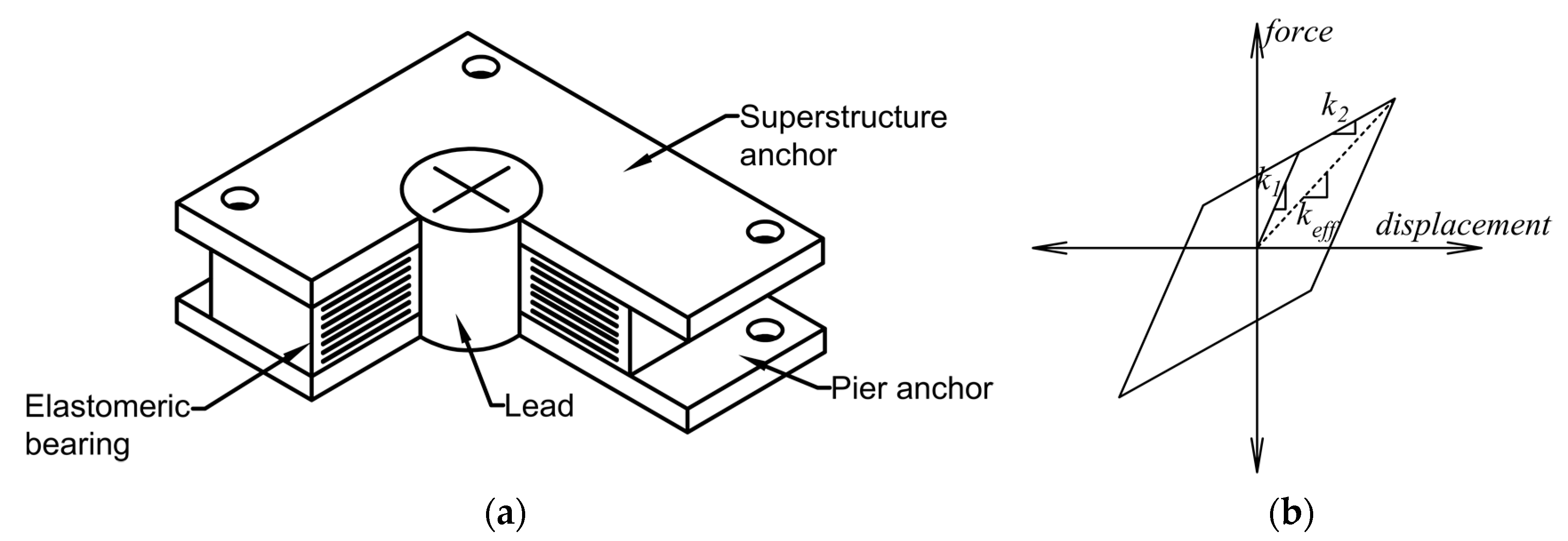
(11)
Several studies have shown the effectiveness of elastomeric bearings for tanks with fixed liquid storage levels. However, some studies have shown that the effectiveness of the elastomer isolation system reduces with the fluctuation in the liquid levels inside tanks.
(12)
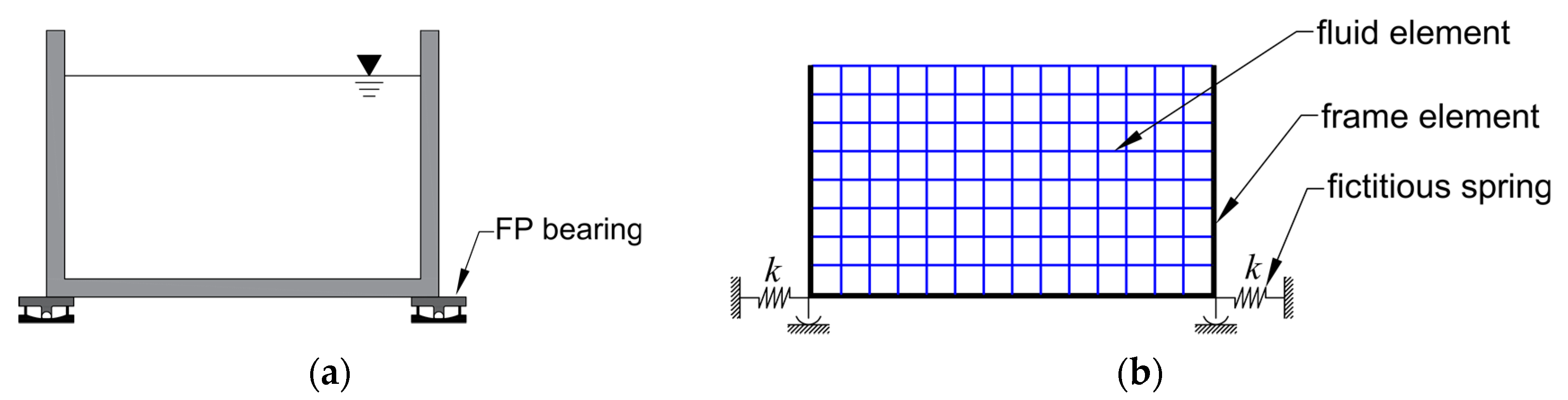
Some researchers have favoured FP bearings over elastomer bearings as the period of isolation of FP bearings is independent of the structure’s weight and stiffness.
(13)
The resonance problem of FPS under pulse-like vibrations led investigators to develop alternative isolators with various geometrical surfaces, such as VFPI, VCFPS, VRFPS, CFPI, and VFFPI, which have non-fixed isolation periods.
(14)
Analysis of isolated structures is quite challenging compared with conventional fixed base structures due to the presence of static and sliding phases. In this regard, models such as fictitious springs and rigid plastic links have been developed.
(15)
For the analysis of isolated tanks due considerations are to be given to the combined effects of FSI and SSI. Thus, numerical methods have been found to be more appropriate for the accurate analysis of isolated tanks.
(16)
Though base isolation systems are effective in reducing the seismic demand of storage tanks, it has been observed that the sloshing period has a tendency to match the isolation period, leading to the sloshing resonance problem.
(17)
Several alternative techniques can be used to solve the sloshing resonance issue, such as using baffles which act as dampers or incorporating hybrid systems with a damper–isolator combination.

Author Contributions

Conceptualization, M.C., A.K. and A.R.A.; resources, M.C.; writing—original draft preparation, M.C.; writing—review and editing, A.K. and A.R.A.; visualization, M.C.; supervision, A.K.; project administration, A.K.; All authors have read and agreed to the published version of the manuscript.

Funding

This research received no external funding. The APC was funded by Manipal Academy of Higher Education, Manipal.

Institutional Review Board Statement

Not applicable.

Informed Consent Statement

Not applicable.

Data Availability Statement

No new data were created or analysed in this study. Data sharing is not applicable to this article.

Conflicts of Interest

The authors declare no conflict of interest.

References

  1. THE 17 GOALS|Sustainable Development. Available online: https://sdgs.un.org/goals (accessed on 17 June 2023).
  2. Haroun, M.A. Dynamic Analyses of Liquid Storage Tanks; Report No. EERL 80–4; Earthquake Engineering Research Laboratory, California Institute of Technology: Pasadena, CA, USA, 1980. [Google Scholar]
  3. Razzaghi, M.S.; Eshghi, S. Behavior of Steel Oil Tanks Due to Near-Fault Ground Motion. In Proceedings of the 13th World Conference on Earthquake Engineering, Vancouver, BC, Canada, 1–6 August 2004. [Google Scholar]
  4. Yazici, G.; Cili, F. Evaluation of the Liquid Storage Tank Failures in the 1999 Kocaeli Earthquake. In Proceedings of the 14th World Conference on Earthquake Engineering, Beijing, China, 12–17 October 2008. [Google Scholar]
  5. Ibata, T.; Nakachi, I.; Ishida, K.; Yokozawa, J. Damage to Storage Tanks Caused by the 2011 Tohoku Earthquake and Tsunami and Proposal for Structural Assessment Method for Cylindrical Storage Tanks. In Proceedings of the 17th International Conference & Exhibition on Liquefied Natural Gas (LNG17), Houston, TX, USA, 16–19 April 2013. [Google Scholar]
  6. Niwa, A.; Clough, R.W. Buckling of Cylindrical Liquid-Storage Tanks under Earthquake Loading. Earthq. Eng. Struct. Dyn. 1982, 10, 107–122. [Google Scholar] [CrossRef]
  7. Housner, G.W. The Dynamic Behavior of Water Tanks. Bull. Seismol. Soc. Am. 1963, 53, 381–387. [Google Scholar] [CrossRef]
  8. Edwards, N.W. A Procedure for the Dynamic Analysis of Thin Walled Cylindrical Liquid Storage Tanks Subjected to Lateral Ground Motions; University of Michigan: Ann Arbor, MI, USA, 1969. [Google Scholar]
  9. Yasuo, S.; Yamaguchi, R. Vibration of a Building upon an Elastic Foundation. Bull. Earthq. Res. Inst. Tokyo Univ. 1957, 35, 545–565. [Google Scholar] [CrossRef]
  10. Parmelee, R.A. Building-Foundation Interaction Effects. J. Eng. Mech. Div. 1967, 93, 131–152. [Google Scholar] [CrossRef]
  11. Sarrazin-Arellano, M. Soil-Structure Interaction in Earthquake Resistant Design; Department of Civil Engineering, School of Engineering, Massachusetts Institute of Technology: Cambridge, MA, USA, 1970. [Google Scholar]
  12. Scavuzzo, R.J.; Bailey, J.L.; Raftopoulos, D.D. Lateral Structure Interaction with Seismic Waves. J. Appl. Mech. 1971, 38, 125–134. [Google Scholar] [CrossRef]
  13. Wolf, J.P. Dynamic Soil-Structure Interaction; Prentice-Hall: Englewood Cliffs, NJ, USA, 1985; ISBN 9780471486824/0471486825. [Google Scholar]
  14. Panchal, V.R.; Soni, D.P. Seismic Behaviour of Isolated Fluid Storage Tanks: A-State-of-the-Art Review. KSCE J. Civil. Eng. 2014, 18, 1097–1104. [Google Scholar] [CrossRef]
  15. Kelly, J.M. Aseismic Base Isolation: Review and Bibliography. Soil. Dyn. Earthq. Eng. 1986, 5, 202–216. [Google Scholar] [CrossRef]
  16. Buckle, I.G.; Mayes, R.L. Seismic Isolation: History, Application, and Performance—A World View. Earthq. Spectra 1990, 6, 161–201. [Google Scholar] [CrossRef]
  17. Jangid, R.S.; Datta, T.K. Seismic Behaviour of Base-Isolated Buildings: A State-of-the Art Review. Proc. Inst. Civil. Eng. Struct. Build. 1995, 110, 186–203. [Google Scholar] [CrossRef]
  18. Girish, M.; Pranesh, M. Sliding Isolation Systems: State-of-the-Art Review. In Proceedings of the Second International Conference on Emerging Trends in Engineering (SICETE), Nagpur, India, 16–18 December 2013; pp. 30–35. [Google Scholar]
  19. Calvi, P.M.; Calvi, G.M. Historical Development of Friction-Based Seismic Isolation Systems. Soil. Dyn. Earthq. Eng. 2018, 106, 14–30. [Google Scholar] [CrossRef]
  20. De Luca, A.; Guidi, L.G. State of Art in the Worldwide Evolution of Base Isolation Design. Soil. Dyn. Earthq. Eng. 2019, 125, 105722. [Google Scholar] [CrossRef]
  21. Avinash, A.R.; Krishnamoorthy, A.; Kamath, K.; Chaithra, M. Sliding Isolation Systems: Historical Review, Modeling Techniques, and the Contemporary Trends. Buildings 2022, 12, 1997. [Google Scholar] [CrossRef]
  22. Rammerstorfer, F.G.; Scharf, K.; Fisher, F.D. Storage Tanks under Earthquake Loading. Appl. Mech. Rev. 1990, 43, 261–282. [Google Scholar] [CrossRef]
  23. Saha, S.K.; Matsagar, V.A.; Jain, A.K. Reviewing Dynamic Analysis of Base-Isolated Cylindrical Liquid Storage Tanks under near-Fault Earthquakes. IES J. Part. A Civil. Struct. Eng. 2015, 8, 41–61. [Google Scholar] [CrossRef]
  24. Westergaard, H.M. Water Pressures on Dams during Earthquakes. Trans. Am. Soc. Civil. Eng. 1933, 98, 418–433. [Google Scholar] [CrossRef]
  25. Hoskins, L.M.; Jacobsen, L.S. Water Pressure in a Tank Caused by a Simulated Earthquake*. Bull. Seismol. Soc. Am. 1934, 24, 1–32. [Google Scholar] [CrossRef]
  26. Housner, G.W. Dynamic Pressures on Accelerated Fluid Containers. Bull. Seismol. Soc. Am. 1957, 47, 15–35. [Google Scholar] [CrossRef]
  27. Biot, M.A. Analytical And Experimental Methods in Engineering Seismology. Trans. Am. Soc. Civil. Eng. 1943, 108, 365–385. [Google Scholar] [CrossRef]
  28. Housner, G.W.; Martel, R.R.; Alford, J.L. Spectrum Analysis of Strong-Motion Earthquakes*. Bull. Seismol. Soc. Am. 1953, 43, 97–119. [Google Scholar] [CrossRef]
  29. United States Atomic Energy Commission. Others Nuclear Reactors and Earthquakes; United States Atomic Energy Commission: Washington, DC, USA, 1963.
  30. Wozniak, R.S.; Mitchell, W.W. Basis of Seismic Design Provisions for Welded Steel Oil Storage Tanks; Chicago Bridge & Iron Company: Toronto, ON, Canada, 1978. [Google Scholar]
  31. Veletsos, A.S. Seismic Effects in Flexible Liquid Storage Tanks. In Proceedings of the 5th World Conference on Earthquake Engineering, Rome, Italy, 1974; Volume 1, pp. 630–639. [Google Scholar]
  32. Chopra, A.K. Reservoir-Dam Interaction during Earthquakes. Bull. Seismol. Soc. Am. 1967, 57, 675–687. [Google Scholar] [CrossRef]
  33. Chopra, A.K. Earthquake Behavior of Reservoir-Dam Systems. J. Eng. Mech. Div. 1968, 94, 1475–1500. [Google Scholar] [CrossRef]
  34. Haroun, M.A.; Housner, G.W. Seismic Design of Liquid Storage Tanks. J. Tech. Counc. ASCE 1981, 107, 191–207. [Google Scholar] [CrossRef]
  35. Haroun, M.A.; Housner, G.W. Earthquake Response of Deformable Liquid Storage Tanks. J. Appl. Mech. 1981, 48, 411–418. [Google Scholar] [CrossRef]
  36. Haroun, M.A.; Tayel, M.A. Dynamic Behavior of Cylindrical Liquid Storage Tanks under Vertical Earthquake Excitation. In Proceedings of the 8th World Conference on Earthquake Engineering, San Francisco, CA, USA, 21–28 July 1984; pp. 421–428. [Google Scholar]
  37. Haroun, M.A.; Ellaithy, H.M. Seismically Induced Fluid Forces on Elevated Tanks. J. Tech. Top. Civil. Eng. 1985, 111, 1–15. [Google Scholar] [CrossRef]
  38. Haroun, M.A.; Tayel, M.A. Axisymmetrical Vibrations, of Tanks—Analytical. J. Eng. Mech. 1985, 111, 346–358. [Google Scholar] [CrossRef]
  39. Haroun, M.A.; Tayel, M.A. Axisymmetrical Vibrations of Tanks—Numerical. J. Eng. Mech. 1985, 111, 329–345. [Google Scholar] [CrossRef]
  40. Haroun, M.A.; Tayel, M.A. Response of Tanks to Vertical Seismic Excitations. Earthq. Eng. Struct. Dyn. 1985, 13, 583–595. [Google Scholar] [CrossRef]
  41. Malhotra, P.K.; Wenk, T.; Wieland, M. Simple Procedure for Seismic Analysis of Liquid-Storage Tanks. Struct. Eng. Int. 2000, 10, 197–201. [Google Scholar] [CrossRef] [Green Version]
  42. Veletsos, A.S.; Yang, J. Earthquake Response of Liquid-Storage Tanks. In Proceedings of the Second Annual Engineering Mechanics Division Specialty Conference, North Carolina, CL, USA, 23–25 May 1977; pp. 1–24. [Google Scholar]
  43. Veletsos, A.S. Seismic Response and Design of Liquid Storage Tanks. Guidel. Seism. Des. Oil Gas Pipeline Syst. 1984, 102, 255–370. [Google Scholar]
  44. Veletsos, A.S.; Tang, Y. Soil-Structure Interaction Effects for Laterally Excited Liquid Storage Tanks. Earthq. Eng. Struct. Dyn. 1990, 19, 473–496. [Google Scholar] [CrossRef]
  45. Tsipianitis, A.; Tsompanakis, Y.; Psarropoulos, P.N. Impact of Dynamic Soil–Structure Interaction on the Response of Liquid-Storage Tanks. Front. Built Environ. 2020, 6, 140. [Google Scholar] [CrossRef]
  46. Ibrahim, R.A.; Pilipchuk, V.N.; Ikeda, T. Recent Advances in Liquid Sloshing Dynamics. Appl. Mech. Rev. 2001, 54, 133–199. [Google Scholar] [CrossRef]
  47. Hsiung, H.C.H. Dynamic Analysis of Hydroelastic Systems Using the Finite-Element Method; University of Southern California: Los Angeles, CA, USA, 1973. [Google Scholar]
  48. Shaaban, S.H.; Nash, W.A. Finite Element Analysis of a Seismically Excited Cylindrical Storage Tank, Ground Supported, and Partially Filled with Liquid; University of Massachusetts: Amherst, MA, USA, 1975. [Google Scholar]
  49. Balendra, T.; Nash, W.A. Earthquake Analysis of a Cylindrical Liquid Storage Tank with a Dome by Finite Element Method; University of Massachusetts: Amherst, MA, USA, 1978. [Google Scholar]
  50. Livaoğlu, R.; Doğangün, A. Simplified Seismic Analysis Procedures for Elevated Tanks Considering Fluid–Structure–Soil Interaction. J. Fluids Struct. 2006, 22, 421–439. [Google Scholar] [CrossRef]
  51. Wilson, E.L.; Khalvati, M. Finite Elements for the Dynamic Analysis of Fluid-Solid Systems. Int. J. Numer. Methods Eng. 1983, 19, 1657–1668. [Google Scholar] [CrossRef]
  52. Haroun, M.A.; Housner, G.W. Dynamic Characteristics of Liquid Storage Tanks. J. Eng. Mech. Div. 1982, 108, 783–800. [Google Scholar] [CrossRef]
  53. Haroun, M.A.; Housner, G.W. Complications in Free Vibration Analysis of Tanks. J. Eng. Mech. Div. 1982, 108, 801–818. [Google Scholar] [CrossRef]
  54. Barton, D.C.; Parker, J.V. Finite Element Analysis of the Seismic Response of Anchored and Unanchored Liquid Storage Tanks. Earthq. Eng. Struct. Dyn. 1987, 15, 299–322. [Google Scholar] [CrossRef]
  55. Zeiny, A. Simplified Modeling of Liquid-Structure Interaction in the Seismic Analysis of Cylindrical Liquid Storage Tanks. In Proceedings of the 13th World Conference on Earthquake Engineering, Vancouver, BC, Canada, 1–6 August 2004; p. 1914. [Google Scholar]
  56. Zhuang, Z.; Liu, H.; Li, Q.; Yamaguchi, S.; Toyoda, M. Development of a New Added Mass Model and Dynamic Analysis for Cylindrical Tank. In Proceedings of the ASME 2006 Pressure Vessels and Piping/ICPVT-11 Conference. Volume 8: Seismic Engineering, Vancouver, BC, Canada, July 2006; Volume 2006, pp. 239–248. [Google Scholar]
  57. Shantaram, D.; Owen, D.R.J.; Zienkiewicz, O.C. Dynamic Transient Behaviour of Two- and Three-Dimensional Structures Including Plasticity, Large Deformation Effects and Fluid Interaction. Earthq. Eng. Struct. Dyn. 1976, 4, 561–578. [Google Scholar] [CrossRef]
  58. Wilson, E.L. Finite Elements for Foundations, Joints and Fluids; Gudehus, G., Ed.; John Wiley & Sons Ltd.: Chichester, UK, 1977; pp. 319–350. [Google Scholar]
  59. Olson, L.G.; Bathe, K.-J. A Study of Displacement-Based Fluid Finite Elements for Calculating Frequencies of Fluid and Fluid-Structure Systems. Nucl. Eng. Des. 1983, 76, 137–151. [Google Scholar] [CrossRef] [Green Version]
  60. Chopra, A.K.; Wilson, E.L.; Farhoomand, I. Earthquake Analysis of Reservoir-Dam Systems. In Proceedings of the 4th World Conference on Earthquake Engineering, Santiago, Chile, 13–18 January 1969; pp. 1–10. [Google Scholar]
  61. Zienkiewicz, O.C.; Bettess, P. Fluid-Structure Dynamic Interaction and Wave Forces. An Introduction to Numerical Treatment. Int. J. Numer. Methods Eng. 1978, 13, 1–16. [Google Scholar] [CrossRef]
  62. Belytschko, T. Methods and Programs for Analysis of Fluid-Structure Systems. Nucl. Eng. Des. 1977, 42, 41–52. [Google Scholar] [CrossRef]
  63. Bathe, K.-J.; Sonnad, V. On Effective Implicit Time Integration in Analysis of Fluid-Structure Problems. Int. J. Numer. Methods Eng. 1980, 15, 943–948. [Google Scholar] [CrossRef] [Green Version]
  64. Doǧangün, A.; Durmuş, A.; Ayvaz, Y. Static and Dynamic Analysis of Rectangular Tanks by Using the Lagrangian Fluid Finite Element. Comput. Struct. 1996, 59, 547–552. [Google Scholar] [CrossRef]
  65. Dogangun, A.; Livaoglu, R. Hydrodynamic Pressures Acting on the Walls of Rectangular Fluid Containers. Struct. Eng. Mech. 2004, 17, 203–214. [Google Scholar] [CrossRef]
  66. Farzin, A. Nonlinear Dynamic Response of Seismically Excited Rectangular Concrete Liquid Filled Tanks; Ryerson University Toronto: Toronto, ON, Canada, 2018. [Google Scholar]
  67. Xu, Z.; Han, Z.; Qu, H. Comparison between Lagrangian and Eulerian Approaches for Prediction of Particle Deposition in Turbulent Flows. Powder Technol. 2020, 360, 141–150. [Google Scholar] [CrossRef]
  68. Azarpira, M.; Zarrati, A.; Farrokhzad, P. Comparison between the Lagrangian and Eulerian Approach in Simulation of Free Surface Air-Core Vortices. Water 2021, 13, 726. [Google Scholar] [CrossRef]
  69. Zienkiewicz, O.C.; Taylor, R.L. The Finite Element Method; Volume 2: Solid. and Fluid. Mechanics Dynamics and Non-Linearity; Wiley: New York, NY, USA, 1991. [Google Scholar]
  70. MacNeal, R.H.; Citerley, R.; Chargin, M. A New Method for Analyzing Fluid-Structure Interaction Using MSC-NASTRAN. In Proceedings of the 5th International Conference on Structural Mechanics in Reactor Technology, Berlin, Germany, 13–17 August 1979; Paper B4/9. pp. 1–9. [Google Scholar]
  71. Balendra, T.; Ang, K.K.; Paramasivam, P.; Lee, S.L. Free Vibration Analysis of Cylindrical Liquid Storage Tanks. Int. J. Mech. Sci. 1982, 24, 47–59. [Google Scholar] [CrossRef]
  72. Babu, S.S.; Bhattacharyya, S.K. Finite Element Analysis of Fluid-Structure Interaction Effect on Liquid Retaining Structures due to Sloshing. Comput. Struct. 1996, 59, 1165–1171. [Google Scholar] [CrossRef]
  73. Aslam, M. Finite Element Analysis of Earthquake-Induced Sloshing in Axisymmetric Tanks. Int. J. Numer. Methods Eng. 1981, 17, 159–170. [Google Scholar] [CrossRef]
  74. Brebbia, C.A.; Dominguez, J. Boundary Elements: An Introductory Course; WIT Press: Southampton, UK; Computational Mechanics Publications: Southampton, UK, 1992; Volume 58, ISBN 978-1-85312-349-8. [Google Scholar]
  75. Jablonski, A.M.; Humar, J.L. Three-Dimensional Boundary Element Reservoir Model for Seismic Analysis of Arch and Gravity Dams. Earthq. Eng. Struct. Dyn. 1990, 19, 359–376. [Google Scholar] [CrossRef] [Green Version]
  76. Wepf, D.H.; Wolf, J.P.; Bachmann, H. Hydrodynamic-Stiffness Matrix Based on Boundary Elements for Time-Domain Dam-Reservoir-Soil Analysis. Earthq. Eng. Struct. Dyn. 1988, 16, 417–432. [Google Scholar] [CrossRef]
  77. Humar, J.L.; Jablonski, A.M. Boundary Element Reservoir Model for Seismic Analysis of Gravity Dams. Earthq. Eng. Struct. Dyn. 1988, 16, 1129–1156. [Google Scholar] [CrossRef]
  78. Park, J.-H.; Koh, H.M.; Kim, J. Fluid-Structure Interaction Analysis by a Coupled Boundary Element-Finite Element Method in Time Domain. In Boundary Element Technology VII; Springer Netherlands: Dordrecht, The Netherlands, 1992; pp. 227–243. [Google Scholar]
  79. Lay, K.S. Seismic Coupled Modeling of Axisymmetric Tanks Containing Liquid. J. Eng. Mech. 1993, 119, 1747–1761. [Google Scholar] [CrossRef]
  80. Koh, H.M.; Kim, J.K.; Park, J.-H. Fluid-Structure Interaction Analysis of 3-D Rectangular Tanks by a Variationally Coupled BEM-FEM and Comparison with Test Results. Earthq. Eng. Struct. Dyn. 1998, 27, 109–124. [Google Scholar] [CrossRef]
  81. Kim, M.K.; Lim, Y.M.; Cho, S.Y.; Cho, K.H.; Lee, K.W. Seismic Analysis of Base-Isolated Liquid Storage Tanks Using the BE–FE–BE Coupling Technique. Soil. Dyn. Earthq. Eng. 2002, 22, 1151–1158. [Google Scholar] [CrossRef]
  82. Shekari, M.R.; Khaji, N.; Ahmadi, M.T. A Coupled BE–FE Study for Evaluation of Seismically Isolated Cylindrical Liquid Storage Tanks Considering Fluid–Structure Interaction. J. Fluids Struct. 2009, 25, 567–585. [Google Scholar] [CrossRef]
  83. Martel, R.R. Effect of Foundation on Earthquake Motion. Civil. Eng. ASCE 1940, 10, 7–10. [Google Scholar]
  84. Singhal, A.; Tahiani, C. Influence of Soil-Structure Interaction on the Earthquake Response of Buildings. Can. Geotech. J. 1969, 6, 177–195. [Google Scholar] [CrossRef]
  85. Ishizaki, H.; Hatakeyama, N. Experimental and Numerical Studies on Vibrations of Buildings. In Proceedings of the Second World Conference on Earthquake Engineering, Tokyo and Kyoto, Japan, 11–18 July 1960; pp. 1263–1284. [Google Scholar]
  86. Merritt, R.G.; Housner, G.W. Effect of Foundation Compliance on Earthquake Stresses in Multistory Buildings. Bull. Seismol. Soc. Am. 1954, 44, 551–569. [Google Scholar] [CrossRef]
  87. Lycan, D.L.; Newmark, N.M. Effect of Structure and Foundation Interaction. J. Eng. Mech. Div. 1961, 87, 1–31. [Google Scholar] [CrossRef]
  88. Bielak, J. Earthquake Response of Building-Foundation Systems; Report EERL 71–04; Earthquake Engineering Research Laboratory, California Institute of Technology: Pasadena, CA, USA, 1971; Volume 71. [Google Scholar]
  89. Meek, J.W.; Veletsos, A.S. Dynamic Analysis and Behavior of Structure-Foundation Systems; SRR Report 13; Department of Civil Engineering, Rice University: Houston, TX, USA, 1972. [Google Scholar]
  90. Jennings, P.C.; Bielak, J. Dynamics of Building-Soil Interaction. Bull. Seismol. Soc. Am. 1973, 63, 9–48. [Google Scholar] [CrossRef]
  91. Veletsos, A.S.; Meek, J.W. Dynamic Behaviour of Building-Foundation Systems. Earthq. Eng. Struct. Dyn. 1974, 3, 121–138. [Google Scholar] [CrossRef]
  92. Krishnamoorthy, A.; Anitha, S. Seismic Effect of Soil Structure Interaction on Plane Frame Structure. J. Mech. Civil. Eng. 2014, 2, 55–60. [Google Scholar]
  93. Chopra, A.K.; Chakrabarti, P.; Gupta, S. Earthquake Response of Concrete Gravity Dams. Including Hydrodynamic and Foundation Interaction Effects; Report No. UCB/EERC-80/01; Earthquake Engineering Research Center, University of California: Berkeley, CA, USA, 1980. [Google Scholar]
  94. Chopra, A.K.; Gupta, S. Hydrodynamic and Foundation Interaction Effects in Earthquake Response of a Concrete Gravity Dam. J. Struct. Div. 1981, 107, 1399–1412. [Google Scholar] [CrossRef]
  95. Chandrashaker, R.; Humar, J.L. Fluid–Foundation Interaction in the Seismic Response of Gravity Dams. Earthq. Eng. Struct. Dyn. 1993, 22, 1067–1084. [Google Scholar] [CrossRef]
  96. Chen, M.; Penzien, J. Nonlinear Soil-Structure Interaction of Skew Highway Bridges; Technical Report UCB/EERC-77/24; Earthquake Engineering Research Center, University of California: Berkeley, CA, USA, 1977. [Google Scholar]
  97. Crouse, C.B.; Hushmand, B.; Martin, G.R. Dynamic Soil–Structure Interaction of a Single-Span Bridge. Earthq. Eng. Struct. Dyn. 1987, 15, 711–729. [Google Scholar] [CrossRef]
  98. Spyrakos, C.C. Assessment of SSI on the Longitudinal Seismic Response Short Span Bridges. Constr. Build. Mater. 1990, 4, 170–175. [Google Scholar] [CrossRef]
  99. Spyrakos, C.C.; Vlassis, A.G. Effect of Soil-Structure Interaction on Seismically Isolated Bridges. J. Earthq. Eng. 2002, 6, 391–429. [Google Scholar] [CrossRef]
  100. Veletsos, A.S.; Tang, Y. Dynamics of Vertically Excited Liquid Storage Tanks. J. Struct. Eng. 1986, 112, 1228–1246. [Google Scholar] [CrossRef]
  101. Haroun, M.A.; Abou-Izzeddine, W. Parametric Study of Seismic Soil-Tank Interaction. II: Vertical Excitation. J. Struct. Eng. 1992, 118, 798–811. [Google Scholar] [CrossRef]
  102. Malhotra, P.K. Seismic Response of Soil-Supported Unanchored Liquid-Storage Tanks. J. Struct. Eng. 1997, 123, 440–450. [Google Scholar] [CrossRef] [Green Version]
  103. Chatterjee, P.; Basu, B. Non-Stationary Seismic Response of Tanks with Soil Interaction by Wavelets. Earthq. Eng. Struct. Dyn. 2001, 30, 1419–1437. [Google Scholar] [CrossRef]
  104. Larkin, T. Seismic Response of Liquid Storage Tanks Incorporating Soil Structure Interaction. J. Geotech. Geoenviron. Eng. 2008, 134, 1804–1814. [Google Scholar] [CrossRef]
  105. Meng, X.; Li, X.; Xu, X.; Zhang, J.; Zhou, W.; Zhou, D. Earthquake Response of Cylindrical Storage Tanks on an Elastic Soil. J. Vib. Eng. Technol. 2019, 7, 433–444. [Google Scholar] [CrossRef]
  106. Wu, W.-H.; Lee, W.-H. Systematic Lumped-Parameter Models for Foundations Based on Polynomial-Fraction Approximation. Earthq. Eng. Struct. Dyn. 2002, 31, 1383–1412. [Google Scholar] [CrossRef]
  107. Tang, Y.K.; Tang, H.T.; Kassawara, R.P.; Stepp, J.C. Validation of Soil-Structure Interaction Methods Using Earthquake Data in Lotung, Taiwan. In Proceedings of the 9th World Conference on Earthquake Engineering, Tokyo and Kyoto, Japan, 2–9 August 1988; Volume 8, p. 321. [Google Scholar]
  108. Cho, K.H.; Kim, M.K.; Lim, Y.M.; Cho, S.Y. Seismic Response of Base-Isolated Liquid Storage Tanks Considering Fluid–Structure–Soil Interaction in Time Domain. Soil. Dyn. Earthq. Eng. 2004, 24, 839–852. [Google Scholar] [CrossRef]
  109. Kianoush, M.R.; Ghaemmaghami, A.R. The Effect of Earthquake Frequency Content on the Seismic Behavior of Concrete Rectangular Liquid Tanks Using the Finite Element Method Incorporating Soil–Structure Interaction. Eng. Struct. 2011, 33, 2186–2200. [Google Scholar] [CrossRef]
  110. Chaithra, M.; Krishnamoorthy, A.; Naurin Nafisa, P.M. Analysis of Soil—Structure Interaction on Response of Tanks Filled with Fluid. Int. J. Civil. Eng. Technol. 2017, 8, 813–819. [Google Scholar]
  111. Chaithra, M.; Krishnamoorthy, A. Soil Structure Interaction Analysis of Tanks Filled with Fluid Subjected to Near-Fault Earthquakes. In Lecture Notes in Civil Engineering; Springer: Singapore, 2022; Volume 162, pp. 551–562. [Google Scholar]
  112. Naeim, F.; Kelly, J.M. Design of Seismic Isolated Structures: From Theory to Practice; John Wiley & Sons, Inc.: Hoboken, NJ, USA, 1999; ISBN 9780470172742. [Google Scholar]
  113. Robinson, W.H. Lead-Rubber Hysteretic Bearings Suitable for Protecting Structures during Earthquakes. Earthq. Eng. Struct. Dyn. 1982, 10, 593–604. [Google Scholar] [CrossRef]
  114. Megget, L.M. Analysis and Design of a Base-Isolated Reinforced Concrete Frame Building. Bull. N. Z. Soc. Earthq. Eng. 1978, 11, 245–254. [Google Scholar] [CrossRef]
  115. Guéraud, R.; Noël-Leroux, J.-P.; Livolant, M.; Michalopoulos, A.P. Seismic Isolation Using Sliding-Elastomer Bearing Pads. Nucl. Eng. Des. 1985, 84, 363–377. [Google Scholar] [CrossRef]
  116. Mostaghel, N.; Khodaverdian, M. Dynamics of Resilient-Friction Base Isolator (R-FBI). Earthq. Eng. Struct. Dyn. 1987, 15, 379–390. [Google Scholar] [CrossRef]
  117. Jangid, R.S.; Londhe, Y.B. Effectiveness of Elliptical Rolling Rods for Base Isolation. J. Struct. Eng. 1998, 124, 469–472. [Google Scholar] [CrossRef]
  118. Zayas, V.A.; Low, S.S.; Mahin, S.A. A Simple Pendulum Technique for Achieving Seismic Isolation. Earthq. Spectra 1990, 6, 317–333. [Google Scholar] [CrossRef]
  119. Pranesh, M.; Sinha, R. VFPI: An Isolation Device for Aseismic Design. Earthq. Eng. Struct. Dyn. 2000, 29, 603–627. [Google Scholar] [CrossRef]
  120. Tsai, C.S.; Chiang, T.-C.; Chen, B.-J. Finite Element Formulations and Theoretical Study for Variable Curvature Friction Pendulum System. Eng. Struct. 2003, 25, 1719–1730. [Google Scholar] [CrossRef]
  121. Lu, L.-Y.; Shih, M.-H.; Wu, C.-Y. Near-Fault Seismic Isolation Using Sliding Bearings with Variable Curvatures. In Proceedings of the 13th World Conference on Earthquake Engineering, Vancouver, BC, Canada, 1–6 August 2004; p. 3264. [Google Scholar]
  122. Krishnamoorthy, A. Seismic Isolation of Bridges Using Variable Frequency and Variable Friction Pendulum Isolator System. Struct. Eng. Int. 2010, 20, 178–184. [Google Scholar] [CrossRef]
  123. Kelly, T.E.; Mayes, R.L. Seismic Isolation of Storage Tanks. In Seismic Engineering: Research and Practice; ASCE: San Francisco, CA, USA, 1989; pp. 408–417. [Google Scholar]
  124. Tajirian, F.F. Seismic Isolation of Critical Components and Tanks. In Proceedings of the ATC-17-1 Seminar on Seismic Isolation, Passive Energy Dissipation and Active Control, San Francisco, CA, USA, 11–12 March 1993; pp. 233–244. [Google Scholar]
  125. Zayas, V.A.; Low, S.S. Application of Seismic Isolation to Industrial Tanks; American Society of Mechanical Engineers: New York, NY, USA, 1995. [Google Scholar]
  126. Malhotra, P.K. New Method for Seismic Isolation of Liquid-Storage Tanks. Earthq. Eng. Struct. Dyn. 1997, 26, 839–847. [Google Scholar] [CrossRef]
  127. Malhotra, P.K. Method for Seismic Base Isolation of Liquid-Storage Tanks. J. Struct. Eng. 1997, 123, 113–116. [Google Scholar] [CrossRef]
  128. Chalhoub, M.S.; Kelly, J.M. Theoretical and Experimental Studies of Cylindrical Water Tanks in Base Isolated Structures; University of California at Berkeley: Berkeley, CA, USA, 1988. [Google Scholar]
  129. Chalhoub, M.S.; Kelly, J.M. Shake Table Test of Cylindrical Water Tanks in Base-Isolated Structures. J. Eng. Mech. 1990, 116, 1451–1472. [Google Scholar] [CrossRef]
  130. Shrimali, M.K.; Jangid, R.S. Non-Linear Seismic Response of Base-Isolated Liquid Storage Tanks to Bi-Directional Excitation. Nucl. Eng. Des. 2002, 217, 1–20. [Google Scholar] [CrossRef]
  131. Liang, B.; Tang, J. Vibration Studies of Base-Isolated Liquid Storage Tanks. Comput. Struct. 1994, 52, 1051–1059. [Google Scholar] [CrossRef]
  132. Jadhav, M.B.; Jangid, R.S. Response of Base-Isolated Liquid Storage Tanks. Shock. Vib. 2004, 11, 33–45. [Google Scholar] [CrossRef]
  133. Jadhav, M.B.; Jangid, R.S. Response of Base-Isolated Liquid Storage Tanks to near-Fault Motions. Struct. Eng. Mech. 2006, 23, 615–634. [Google Scholar] [CrossRef]
  134. Hashemi, S.; Aghashiri, M.H. Seismic Responses of Base-Isolated Flexible Rectangular Fluid Containers under Horizontal Ground Motion. Soil. Dyn. Earthq. Eng. 2017, 100, 159–168. [Google Scholar] [CrossRef]
  135. Saha, S.K.; Sepahvand, K.; Matsagar, V.A.; Jain, A.K.; Marburg, S. Stochastic Analysis of Base-Isolated Liquid Storage Tanks with Uncertain Isolator Parameters under Random Excitation. Eng. Struct. 2013, 57, 465–474. [Google Scholar] [CrossRef]
  136. Safari, S.; Tarinejad, R. Parametric Study of Stochastic Seismic Responses of Base-Isolated Liquid Storage Tanks under near-Fault and Far-Fault Ground Motions. J. Vib. Control 2018, 24, 5747–5764. [Google Scholar] [CrossRef]
  137. Wang, Y.-P.; Teng, M.-C.; Chung, K.-W. Seismic Isolation of Rigid Cylindrical Tanks Using Friction Pendulum Bearings. Earthq. Eng. Struct. Dyn. 2001, 30, 1083–1099. [Google Scholar] [CrossRef]
  138. Panchal, V.R.; Jangid, R.S. Variable Friction Pendulum System for Seismic Isolation of Liquid Storage Tanks. Nucl. Eng. Des. 2008, 238, 1304–1315. [Google Scholar] [CrossRef]
  139. Panchal, V.R.; Jangid, R.S. Seismic Response of Liquid Storage Steel Tanks with Variable Frequency Pendulum Isolator. KSCE J. Civil. Eng. 2011, 15, 1041–1055. [Google Scholar] [CrossRef]
  140. Abalı, E.; Uçkan, E. Parametric Analysis of Liquid Storage Tanks Base Isolated by Curved Surface Sliding Bearings. Soil. Dyn. Earthq. Eng. 2010, 30, 21–31. [Google Scholar] [CrossRef]
  141. Soni, D.P.; Mistry, B.B.; Panchal, V.R. Double Variable Frequency Pendulum Isolator for Seismic Isolation of Liquid Storage Tanks. Nucl. Eng. Des. 2011, 241, 700–713. [Google Scholar] [CrossRef]
  142. Weng, D.; Zhang, R.; Ge, Q.; Liu, S. Effect Investigation of Combination Isolation System for Liquid Storage Tank in Different Seismic Levels. In Proceedings of the 15th World Conference on Earthquake Engineering (15WCEE), Lisbon, Portugal, 24–28 September 2012. [Google Scholar]
  143. Saha, S.K.; Matsagar, V.A.; Jain, A.K. Earthquake Response of Base-Isolated Liquid Storage Tanks for Different Isolator Models. J. Earthq. Tsunami 2014, 8, 1450013. [Google Scholar] [CrossRef]
  144. Saha, S.K.; Matsagar, V.A.; Jain, A.K. Seismic Fragility of Base-Isolated Water Storage Tanks under Non-Stationary Earthquakes. Bull. Earthq. Eng. 2016, 14, 1153–1175. [Google Scholar] [CrossRef]
  145. Bagheri, S.; Farajian, M. The Effects of Input Earthquake Characteristics on the Nonlinear Dynamic Behavior of FPS Isolated Liquid Storage Tanks. J. Vib. Control. 2018, 24, 1264–1282. [Google Scholar] [CrossRef]
  146. Bagheri, S.; Raad, H.H. Seismic Performance Assessment of FPS Isolated Liquid Storage Tanks at Various Intensity Levels. In Proceedings of the Fourth Conference on Smart Monitoring, Assessment and Rehabilitation of Civil Structures, Zurich, Switzerland, 13–15 September 2017. [Google Scholar]
  147. Uckan, E.; Umut, Ö.; Sisman, F.N.; Karimzadeh, S.; Askan, A. Seismic Response of Base Isolated Liquid Storage Tanks to Real and Simulated near Fault Pulse Type Ground Motions. Soil. Dyn. Earthq. Eng. 2018, 112, 58–68. [Google Scholar] [CrossRef]
  148. Christovasilis, I.P.; Whittaker, A.S. Seismic Analysis of Conventional and Isolated LNG Tanks Using Mechanical Analogs. Earthq. Spectra 2008, 24, 599–616. [Google Scholar] [CrossRef]
  149. Kalantari, A.; Nikoomanesh, M.R.; Goudarzi, M.A. Applicability of Mass-Spring Models for Seismically Isolated Liquid Storage Tanks. J. Earthq. Tsunami 2019, 13, 1950002. [Google Scholar] [CrossRef] [Green Version]
  150. Krishnamoorthy, A. Finite Element Method of Analysis for Liquid Storage Tank Isolated with Friction Pendulum System. J. Earthq. Eng. 2021, 25, 82–92. [Google Scholar] [CrossRef]
  151. Yang, Y.-B.; Lee, T.-Y.; Tsai, I.-C. Response of Multi-Degree-of-Freedom Structures with Sliding Supports. Earthq. Eng. Struct. Dyn. 1990, 19, 739–752. [Google Scholar] [CrossRef]
  152. Moslemi, M.; Farzin, A.; Kianoush, M.R. Nonlinear Sloshing Response of Liquid-Filled Rectangular Concrete Tanks under Seismic Excitation. Eng. Struct. 2019, 188, 564–577. [Google Scholar] [CrossRef]
  153. Rawat, A.; Matsagar, V.A.; Nagpal, A.K. Numerical Study of Base-Isolated Cylindrical Liquid Storage Tanks Using Coupled Acoustic-Structural Approach. Soil. Dyn. Earthq. Eng. 2019, 119, 196–219. [Google Scholar] [CrossRef]
  154. Rawat, A.; Mittal, V.; Chakraborty, T.; Matsagar, V. Earthquake Induced Sloshing and Hydrodynamic Pressures in Rigid Liquid Storage Tanks Analyzed by Coupled Acoustic-Structural and Euler-Lagrange Methods. Thin-Walled Struct. 2019, 134, 333–346. [Google Scholar] [CrossRef]
  155. Shekari, M.R.; Hekmatzadeh, A.A.; Amiri, S.M. On the Nonlinear Dynamic Analysis of Base-Isolated Three-Dimensional Rectangular Thin-Walled Steel Tanks Equipped with Vertical Baffle. Thin-Walled Struct. 2019, 138, 79–94. [Google Scholar] [CrossRef]
  156. Vern, S.; Shrimali, M.K.; Bharti, S.D.; Datta, T.K. Response and Damage Evaluation of Base-Isolated Concrete Liquid Storage Tank under Seismic Excitations. Eng. Res. Express 2021, 3, 045002. [Google Scholar] [CrossRef]
  157. Rawat, A.; Matsagar, V. Seismic Analysis of Liquid Storage Tank Using Oblate Spheroid Base Isolation System Based on Rolling Friction. Int. J. Non Linear Mech. 2022, 147, 104186. [Google Scholar] [CrossRef]
  158. Kumar, H.; Saha, S.K. Effects of Soil-Structure Interaction on Seismic Response of Fixed Base and Base Isolated Liquid Storage Tanks. J. Earthq. Eng. 2021, 26, 6148–6171. [Google Scholar] [CrossRef]
  159. Zhang, R.; Zhao, Z.; Pan, C. Influence of Mechanical Layout of Inerter Systems on Seismic Mitigation of Storage Tanks. Soil. Dyn. Earthq. Eng. 2018, 114, 639–649. [Google Scholar] [CrossRef]
  160. Gedikli, A.; Ergüven, M.E. Seismic Analysis of a Liquid Storage Tank with a Baffle. J. Sound. Vib. 1999, 223, 141–155. [Google Scholar] [CrossRef]
  161. Maleki, A.; Ziyaeifar, M. Damping Enhancement of Seismic Isolated Cylindrical Liquid Storage Tanks Using Baffles. Eng. Struct. 2007, 29, 3227–3240. [Google Scholar] [CrossRef]
  162. De Angelis, M.; Giannini, R.; Paolacci, F. Experimental Investigation on the Seismic Response of a Steel Liquid Storage Tank Equipped with Floating Roof by Shaking Table Tests. Earthq. Eng. Struct. Dyn. 2010, 39, 377–396. [Google Scholar] [CrossRef]
  163. Maleki, A.; Ziyaeifar, M. Sloshing Damping in Cylindrical Liquid Storage Tanks with Baffles. J. Sound. Vib. 2008, 311, 372–385. [Google Scholar] [CrossRef]
  164. Krishnamoorthy, A. Variable Curvature Pendulum Isolator and Viscous Fluid Damper for Seismic Isolation of Structures. J. Vib. Control. 2011, 17, 1779–1790. [Google Scholar] [CrossRef]
  165. Tsipianitis, A.; Tsompanakis, Y. Improving the Seismic Performance of Base-Isolated Liquid Storage Tanks with Supplemental Linear Viscous Dampers. Earthq. Eng. Eng. Vib. 2022, 21, 269–282. [Google Scholar] [CrossRef]
  166. Chang, S.-P.; Makris, N.; Whittaker, A.S.; Thompson, A.C.T. Experimental and Analytical Studies on the Performance of Hybrid Isolation Systems. Earthq. Eng. Struct. Dyn. 2002, 31, 421–443. [Google Scholar] [CrossRef]
  167. Luo, H.; Zhang, R.; Weng, D. Mitigation of Liquid Sloshing in Storage Tanks by Using a Hybrid Control Method. Soil. Dyn. Earthq. Eng. 2016, 90, 183–195. [Google Scholar] [CrossRef]
  168. Hartog, J.P.D. LXXIII. Forced Vibrations with Combined Viscous and Coulomb Damping. Lond. Edinb. Dublin Philos. Mag. J. Sci. 1930, 9, 801–817. [Google Scholar] [CrossRef]
  169. Hundal, M.S. Response of a Base Excited System with Coulomb and Viscous Friction. J. Sound. Vib. 1979, 64, 371–378. [Google Scholar] [CrossRef]
  170. Qamaruddin, M.; Rasheeduzzafar; Arya, A.S.; Chandra, B. Seismic Response of Masonry Buildings with Sliding Substructure. J. Struct. Eng. 1986, 112, 2001–2011. [Google Scholar] [CrossRef]
  171. Yang, T.Y.; Konstantinidis, D.; Kelly, J.M. The Influence of Isolator Hysteresis on Equipment Performance in Seismic Isolated Buildings. Earthq. Spectra 2010, 26, 275–293. [Google Scholar] [CrossRef]
  172. Mostaghel, N.; Hejazi, M.; Tanbakuchi, J. Response of Sliding Structures to Harmonic Support Motion. Earthq. Eng. Struct. Dyn. 1983, 11, 355–366. [Google Scholar] [CrossRef]
  173. Westermo, B.; Udwadia, F. Periodic Response of a Sliding Oscillator System to Harmonic Excitation. Earthq. Eng. Struct. Dyn. 1983, 11, 135–146. [Google Scholar] [CrossRef]
  174. Li, Z.; Rossow, E.C.; Shah, S.P. Sinusoidal Forced Vibration of Sliding Masonry System. J. Struct. Eng. 1989, 115, 1741–1755. [Google Scholar] [CrossRef]
  175. Jangid, R.S. Response of Pure-Friction Sliding Structures to Bi-Directional Harmonic Ground Motion. Eng. Struct. 1997, 19, 97–104. [Google Scholar] [CrossRef]
  176. Younis, C.J.; Tadjbakhsh, I.G. Response of Sliding Rigid Structure to Base Excitation. J. Eng. Mech. 1984, 110, 417–432. [Google Scholar] [CrossRef]
  177. Crandall, S.H.; Lee, S.S.; Williams, J.H. Accumulated Slip of a Friction-Controlled Mass Excited by Earthquake Motions. J. Appl. Mech. 1974, 41, 1094–1098. [Google Scholar] [CrossRef]
  178. Mostaghel, N.; Tanbakuchi, J. Response of Sliding Structures to Earthquake Support Motion. Earthq. Eng. Struct. Dyn. 1983, 11, 729–748. [Google Scholar] [CrossRef]
  179. Ahmadi, G. Stochastic Earthquake Response of Structures on Sliding Foundation. Int. J. Eng. Sci. 1983, 21, 93–102. [Google Scholar] [CrossRef]
  180. Constantinou, M.C.; Tcidjbakhsh, I.G. Response of a Sliding Structure to Filtered Random Excitation. J. Struct. Mech. 1984, 12, 401–418. [Google Scholar] [CrossRef]
  181. Kulkarni, J.A.; Jangid, R.S. Effects of Superstructure Flexibility on the Response of Base-Isolated Structures. Shock. Vib. 2003, 10, 368693. [Google Scholar] [CrossRef] [Green Version]
  182. Vafai, A.; Hamidi, M.; Ahmadi, G. Numerical Modeling of MDOF Structures with Sliding Supports Using Rigid-Plastic Link. Earthq. Eng. Struct. Dyn. 2001, 30, 27–42. [Google Scholar] [CrossRef]
  183. Rai, D.C. Performance of Elevated Tanks InM w 7.7 Bhuj Earthquake of 26 January 2001. J. Earth Syst. Sci. 2003, 112, 421–429. [Google Scholar] [CrossRef]
  184. Soroushnia, S.; Tafreshi, S.T.; Omidinasab, F.; Beheshtian, N.; Soroushnia, S. Seismic Performance of RC Elevated Water Tanks with Frame Staging and Exhibition Damage Pattern. Procedia Eng. 2011, 14, 3076–3087. [Google Scholar] [CrossRef] [Green Version]
  185. Haroun, M.A.; Abou-Izzeddine, W. Parametric Study of Seismic Soil-Tank Interaction. I: Horizontal Excitation. J. Struct. Eng. 1992, 118, 783–797. [Google Scholar] [CrossRef]
  186. Jain, S.K.; Sameer, S.U. A Review of Requirements in Indian Codes for Aseismic Design of Elevated Water Tanks. Bridge Struct. Eng. 1993, 23, 1–16. [Google Scholar]
  187. Jaiswal, O.R.; Rai, D.C.; Jain, S.K. Review of Seismic Codes on Liquid-Containing Tanks. Earthq. Spectra 2007, 23, 239–260. [Google Scholar] [CrossRef] [Green Version]
  188. Malhotra, P. Practical Nonlinear Seismic Analysis of Tanks. Earthq. Spectra 2000, 16, 473–492. [Google Scholar] [CrossRef]
Figure 1. (a) Tank with partially filled water; (b) equivalent two-mass model, as adapted from [7].
Sustainability 15 11040 g001
Figure 2. Equivalent three mass model, adapted from [34].
Sustainability 15 11040 g002
Figure 3. Mechanical model, as adapted from Malhotra et al. [41].
Sustainability 15 11040 g003
Figure 4. Model of tank considering soil flexibility: (a) actual tank; (b) mechanical model, as adapted from [100].
Sustainability 15 11040 g004
Figure 5. The mechanical model, as adapted from Chatterjee and Basu [103].
Sustainability 15 11040 g005
Figure 6. Model of the tank soil system, as adapted from [104].
Sustainability 15 11040 g006
Figure 7. A combined mechanical model of a tank, fluid, and soil system, as adapted from [105].
Sustainability 15 11040 g007
Figure 8. (a) Lead Rubber bearing (LRB), as adapted from [113]; (b) hysteresis loop for LRB.
Sustainability 15 11040 g008
Figure 9. (a) Typical section of a friction pendulum (FP) isolator; (b) hysteresis loop for FP isolator.
Sustainability 15 11040 g009
Figure 10. (a) Storage tank with FPS; (b) FE discretization of tank and liquid, as adapted from [142].
Sustainability 15 11040 g010
Figure 11. SDOF system with a spring, viscous damping and Coulomb friction [150].
Sustainability 15 11040 g011
Figure 12. A 2DOF system with Coulomb friction, as adapted from [151].
Sustainability 15 11040 g012
Figure 13. A 2DOF system with LRB, as adapted from [152].
Sustainability 15 11040 g013
Figure 14. MDOF model with fictitious spring, as adapted from [163].
Sustainability 15 11040 g014
Figure 15. MDOF model with the rigid plastic link, as adapted from [164].
Sustainability 15 11040 g015
Table 1. Summary of the tank models discussed in the present article.
ReferenceType of TankTank Wall Type (Rigid/Flexible)SSI Effect ConsideredIsolated TankTank Model DescriptionCharacteristics of ElementsType of Dynamic ExcitationType of Analysis
[7,26]Ground supported, elevatedrigid××Two mass system-Seismic-
[31]Ground supportedflexible××SDOF system-Seismic-
[34,35]Ground supportedflexible××Three mass system derived from FE analysis-Seismic-
[41]Ground supportedflexible××Spring–dashpot system with impulsive and convective masses of fluid considering-SeismicLinear
[52,53]Ground supportedflexible××Liquid–tank system is modelled using added mass technique-SeismicLinear, nonlinear
[54]Ground supportedflexible××Liquid–tank system is modelled using added mass technique-SeismicNonlinear
[55]Ground supportedflexible××Liquid–tank system is modelled using added mass technique-SeismicLinear, nonlinear
[56]Ground supportedflexible××Liquid–tank system is modelled using added mass technique-SeismicNonlinear
[64,65]Ground supportedflexible××FE discretization with Lagrangian method for FSI effectLinearSeismicLinear static and linear dynamic
[66]Ground supportedflexible××FE discretization with Lagrangian method for FSI effectLinear, four noded element with 3 DOF at all nodesSeismicNonlinear
[71,72]Ground supportedflexible××FE discretization with Eulerian approach for FSI effectTwo noded ring element with four DOF at each node for tank wall. Eight noded rectangular element for fluid Seismic, harmonicLinear
[73]Ground supportedflexible××FE discretization with Eulerian approach for FSI effectEight-noded isoparametric elementSeismicLinear
[78,79,80,81]Ground supportedflexible××Coupled BE and FE discretization of tank–fluid systemShell element for tank, BE for fluidSeismicLinear
[82]Ground supportedflexible×Coupled BE and FE discretization of tank–fluid systemShell element for tank, linear boundary element for fluid, Bilinear isolatorSeismicNonlinear
[100]Ground supportedflexible×Two-DOF system model. Effect of SSI is modelled using spring–dashpot system-HarmonicLinear
[103]Ground supportedflexible×Two-DOF linear mass–spring–dashpot system-SeismicLinear
[104]Ground supportedflexible×SDOF linear mass–spring–dashpot for tank–fluid system which is attached to soil using two springs and two dampers-Harmonic, seismicLinear
[105]Ground supportedflexible×Fluid is idealized as three mass system. Foundation and soil system is modelled using second-order lumped parameter model-Seismic-
[108]Ground supportedflexibleCoupled BE and FE discretization of tank–fluid system. Soil is represented by spring–dashpot systemNine-noded shell element with 5 DOF at each node for the structure, BE for fluid, nonlinear base isolatorSeismicNonlinear
[109]Ground supportedflexible×FE discretization with Lagrangian method for FSI effectFour-noded shell element with 6 DOF at each node. SeismicLinear
[110,111]Ground supportedflexible×FE discretization with Eulerian approach for FSI effectTwo-noded frame element with 3 DOF per node for tank wall and base, four-noded element with 2 DOF per node for foundation, four-noded element with SDOF for fluid.SeismicLinear
[126,127]Ground supportedflexible×Two-DOF system to model liquid–tank system isolated at base using elastomersNonlinear rubber bearingSeismic-
[137]Ground supportedflexible×MDOF system to model liquid–tank system isolated with FP isolator at base-SeismicNonlinear
[138,139]Ground supportedflexible×Three mass system to model liquid–tank system isolated at base using VFPS-SeismicLinear
[141]Ground supportedflexible×Three mass system to model liquid–tank system isolated at base using double VFPS-SeismicNonlinear
[142]Ground supportedflexible×Three mass system to model liquid–tank system isolated at base using multiple FPS-Seismic-
[150]Ground supportedflexible×FE discretization of tank–liquid system with FP isolator at base.Two-noded frame element with 3 DOF per node for tank wall and base, four-noded element with SDOF for fluid.SeismicLinear
[158]Ground supported, elevatedflexibleThree mass system to model liquid–tank system isolated at base using laminated and lead rubber bearings modelled using spring–dashpot system.Linear and nonlinear isolation bearingsSeismic-
[159]Ground supportedrigid×Three mass system to model liquid-tank system with hybrid isolation system.-SeismicLinear
[160]Ground supportedrigid×BE discretization of isolated tank. Baffles are provided to reduce sloshing effectConstant boundary elementsSeismicLinear
[161,162,163]Ground supportedrigid×Lumped mass model for the isolated tank. Baffles are provided to reduce sloshing effect.-SeismicLinear
[165,166,167]Ground supportedFlexible, rigid×Three mass system to model liquid-tank system with hybrid isolation system.-SeismicLinear
Disclaimer/Publisher’s Note: The statements, opinions and data contained in all publications are solely those of the individual author(s) and contributor(s) and not of MDPI and/or the editor(s). MDPI and/or the editor(s) disclaim responsibility for any injury to people or property resulting from any ideas, methods, instructions or products referred to in the content.

