Article

Numerical Simulation Study on the Evolution Law of Stress and Crack in Coal Seam Hydraulic Fracturing

1
College of Safety Science and Engineering, Xi’an University of Science and Technology, Xi’an 710054, China
2
State Key Laboratory of Gas Disaster Detecting, Preventing and Emergency Controlling, Chongqing 400037, China
*
Author to whom correspondence should be addressed.
Sustainability 2023, 15(14), 11351; https://doi.org/10.3390/su151411351
Submission received: 20 June 2023 / Revised: 17 July 2023 / Accepted: 19 July 2023 / Published: 21 July 2023

Abstract

:
Hydraulic fracturing as a conventional reservoir permeability enhancement technique can effectively increase the production of coalbed methane, and it is important to study the stress and crack evolution law to evaluate the effect of coalbed fracturing and optimize the construction process. To accurately derive the evolution characteristics of stress and the propagation form of cracks during hydraulic fracturing of coal seams, a numerical model of hydraulic fracturing was established based on a three-point bending test of coal samples using the finite-discrete element method (FDEM). Based on a coal seam in a mining area in southwest China, a hydraulic fracturing model was established, and the reliability of the numerical model was verified by comparing the numerical simulation with the analytical expression. The model was used to study the evolution of stress and cracks with time during hydraulic fracturing, and the influence of elastic modulus and permeability on the evolution of stress and cracks was investigated. The results show that stress and cracks in the process of hydraulic fracturing belong to a mutual feeding mechanism during evolution, and the effective permeability range of fracturing is an ellipse with the crack as the long axis enclosed by the effective stress field. The greater the elastic modulus of the coal seam, the greater the crack initiation pressure and the shorter the crack initiation time, and a coal seam with a high elastic modulus is more likely to form complex cracks. The change in coal seam permeability has little effect on the initiation pressure and initiation time, but the crack propagation path is obviously different, and a coal seam with low permeability is more favorable to hydraulic fracturing.

1. Introduction

Coalbed methane (CBM) is a promising alternative to conventional oil and gas resources due to its clean and efficient characteristics [1,2,3]. However, low-porosity and low-permeability coal reservoirs pose a significant challenge to achieving high CBM production [4,5,6]. Hydraulic fracturing, a conventional technique for increasing reservoir permeability, has been shown to effectively enhance the permeability of coal seams and increase CBM production [7,8,9]. During hydraulic fracturing engineering, the fracturing effects will vary depending on factors such as the physical parameters of the coal seams, ground stress, and construction techniques [10,11,12,13]. Therefore, studying the law of stress evolution and crack propagation during hydraulic fracturing is critical for assessing the modifiability of coal seam fracturing, on-site construction, and monitoring the fracturing scope in coal seams.
Numerical simulation has emerged as a widely adopted method for studying crack propagation in hydraulic fracturing, as evidenced by the works of several scholars in the field. Liang Weiguo et al. [14] validated the accuracy of cohesive-type simulated coal rock hydraulic fracturing through true triaxial hydraulic fracturing tests. Huang Laisheng et al. [15] discussed the important role of bedding in the formation of fracking fractures through physical tests and numerical simulation. Jia Jinzhang et al. [16] explored the effects of ground stress, water injection pressure, and elastic modulus on the effective radius of hydraulic fracturing through simulation using ABAQUS software. Lu Yiyu et al. [17] used a fully coupled fluid-flow discrete element method (DEM) to study the effects of the natural planes (NP) approximation angle (the angle between NP and horizontal direction), in situ stress, and fluid injection flow on fracture propagation behavior and fracture pressure. Ma Yulin et al. [18] established a numerical model based on the block discrete element method to simulate the propagation of multiple fractures in reservoirs with bedding planes. Li Yakang et al. [19] studied the influence of different forms of parallel prefabricated cracks on the mechanical properties of a rock–coal combination using a PFC2D numerical simulation.
To summarize, previous studies have predominantly focused on analyzing the impact of various factors on final crack propagation morphology in hydraulic fracturing, relying on classical theories. However, there has been relatively less emphasis on investigating the relationship between stress and crack evolution in hydraulic fracturing, as well as the influence of changes in coal’s pore permeability on crack propagation. Coal seams represent porous media characterized by a dual crack-pore structure, where the pore characteristics of the coal matrix play a significant role. Moreover, the present condition of coal, influenced by different historical maximum burial depths, affects the coal matrix and its pore structure, leading to alterations in the elastic modulus and permeability of the coal seam [20,21,22,23,24]. The numerical models of hydraulic fracturing, based on classical theory, often adopt the fracture criterion of brittle materials as the criterion for hydraulic fracture propagation. However, coal exhibits elastic–plastic behavior. Thus, accurately describing hydraulic fracture propagation in elastic–plastic coal is a crucial aspect of current research [25,26].
The finite-discrete element method (FDEM) is recognized as an effective approach for simulating the internal crack propagation morphology of elastic–plastic materials. This method not only accurately calculates the stress state of continuous media but also captures the interaction between discrete blocks. As a result, it has found widespread application in hydraulic fracturing simulations [27,28,29]. In light of these considerations, the author employs the finite-discrete element method (FDEM) for numerical simulation to construct the response characteristics of the cohesive unit intrinsic relationship fitting coal based on coal fracture characteristics. Furthermore, the evolution of stress and cracks with time during hydraulic fracturing is analyzed within the context of through-strata fracturing. The study also examines the impact of different elastic moduli and permeability on hydraulic fracture propagation. These findings can offer theoretical support for the evaluation of hydraulic fracturing construction processes and the monitoring of fracturing scope.

2. The Establishment of a Finite-Discrete Element Model of Hydraulic Fracturing

The finite-discrete element method (FDEM) incorporates a cohesive element within a divided matrix element, where the matrix element simulates the porous medium and the cohesive element simulates fractures. During the hydraulic fracturing process, it is assumed that water pressure is completely converted into fracture energy. To accurately define the response characteristics of the cohesive element in the finite-discrete element method, it is essential to establish an appropriate constitutive relationship based on the fracture characteristics of coal. In this regard, [30] conducted a three-point bending test on coal samples to examine the nonlinear mechanical behavior of crack propagation. The experimental results provided insights into the mechanical properties of the cohesive element, allowing for the establishment of a constitutive relation in the form of an exponential function, as depicted in Figure 1.
In the figure, the OA segment is a linear damage-free phase, the AB segment is the evolutionary stage of exponential damage, the area s O A B is the total energy release rate G c of the unit fracture, δ m f is the effective displacement when the unit is completely broken, the area s O A δ m 0 is the required elastic energy before the initial damage of the unit, and the corresponding δ m 0 is the effective displacement when the unit is initially damaged. The maximum nominal stress for the damage criterion is selected as the initial damage criterion of the unit. Initial damage is generated when the stress in either direction reaches the critical stress; the expression is:
max { t n t n 0 , t s t s 0 , t t t t 0 } = 1
where t n is the stress in the normal direction of the unit (where the symbol < > indicates that the unit will not appear damaged after the unit is subjected to pure pressure to produce compression deformation), MPa; t s and t t are two tangential stresses of the unit, MPa; t n 0 is the critical stress in the normal direction when the unit fails; t s 0 and t t 0 are the critical stress in both tangential directions when the unit fails, MPa.
Damage evolution begins when the unit meets the criteria for the initial injury. The total fracture energy of the unit that is completely destroyed can be obtained based on the Benzeggagh–Kenane (B–K) criterion; the specific expression is:
G c = G n c + ( G s c G n c ) { G S G T } η
where G c is the total energy release rate of the unit; G n c , G s c are the critical fracture energies causing failure in the normal and tangential directions, respectively; G S is the work done for the traction force in the tangential direction and the corresponding relative displacement component; G T is the work done by the relative displacement conjugated to the traction force in the normal and tangential directions; and η is the material parameter.
Combining Equations (1) and (2) yields the complete expression of the damage variable D for the exponential damage evolution as follows:
D = δ m 0 δ m f T e f f G C G 0 d δ
The damage variable D represents the overall damage of the material and takes into account the combined effect of all evolutionary mechanisms. The initial value of D is 0, and as the damage evolves, D gradually evolves from 0 to 1. The unit reaches full damage when D is 1, and the corresponding δ m f value at this time is the effective displacement of the unit when it is fully damaged.

3. Validation of Finite-Discrete Element Model of Hydraulic Fracturing

3.1. Parameters Selection of Numerical Model

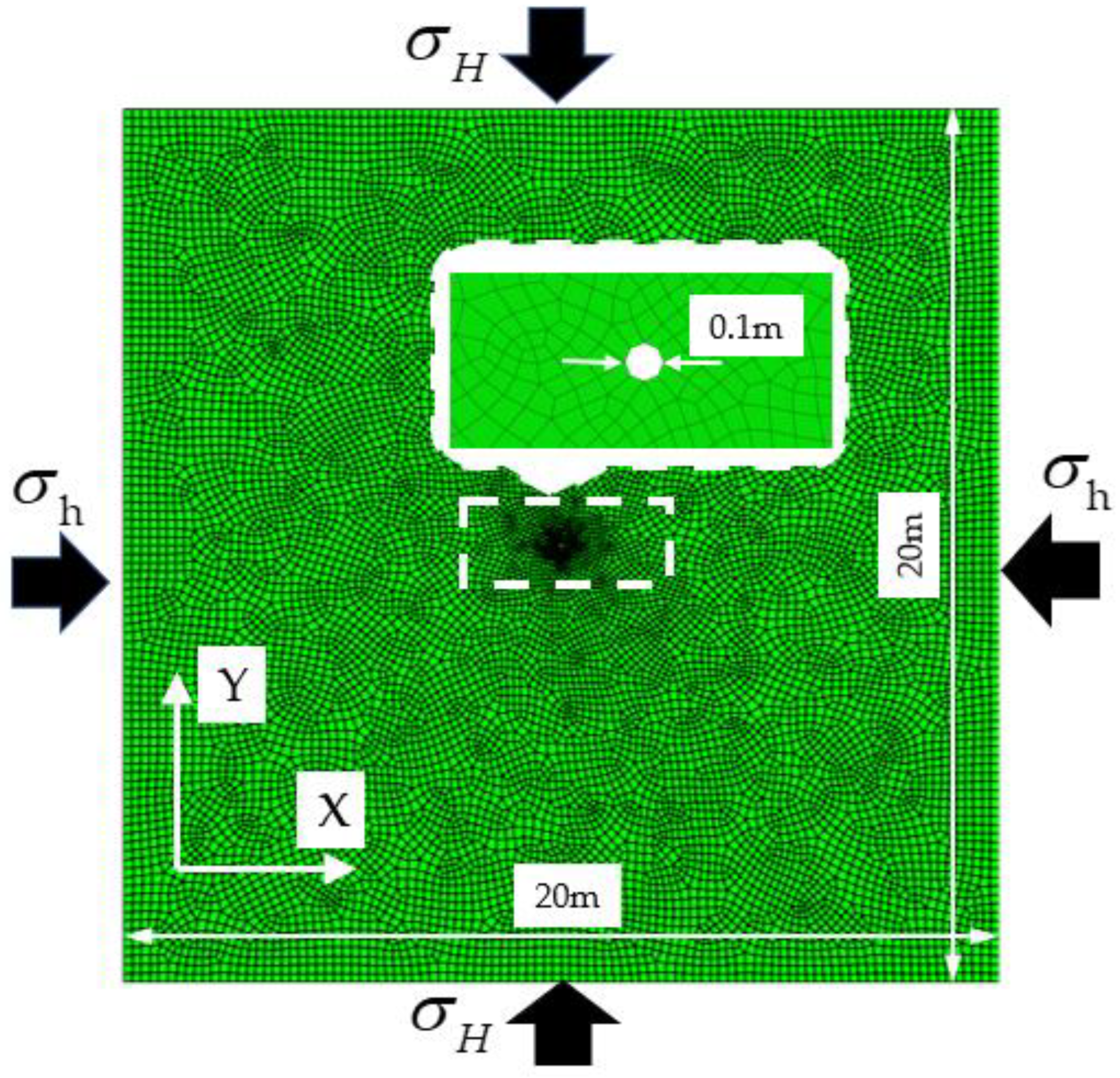
To validate the numerical calculation model, a two-dimensional finite-discrete element model was constructed using a horizontal cross-section of a coal seam from a certain mining area in southwestern China. The coal seam has an average thickness of 2.4 m and is buried at an average depth of 780 m. The maximum horizontal in situ stress is 1.57 times the minimum horizontal ground stress. The coal–rock structure primarily comprises mudstone, sandy mudstone, fine sandstone, and other materials. The model size is 20 m × 20 m, with a fracturing hole of 0.1 m in diameter located at the center of the model. The model was discretized using an irregular quadrilateral mesh, and zero-thickness cohesive elements were embedded between the divided elements. The entire model consists of 39,079 units, including 13,093 matrix units and 25,986 cohesive units, as depicted in Figure 2.
In the constructed model, the Y direction represents the direction of the maximum horizontal principal stress, and the X direction corresponds to the minimum horizontal principal stress direction. The model was subjected to a fixed normal displacement boundary condition, and crustal stress was applied to the elements using the automatic balance method. As effective crustal stress was employed for the units, there was no need to set an initial pore pressure. The material parameters used in the numerical simulation were determined based on the lithology of the mine’s stratum, as outlined in Table 1. The fracturing fluid injection followed a constant flow rate injection method. To ensure convergence of the model’s initial state, the amplitude curve was set to gradually increase the injection flow rate from 0 to the target value of 0.003 m3/s within a duration of 1 s.

3.2. Comparative Analysis of Simulation Results

In this study, the finite-discrete element method was employed to establish the hydraulic fracturing calculation model, incorporating a defined nonlinear exponential damage evolution form. Previous research has indicated that the fracture pressure formula based on the Hoek–Brown (HB) strength criterion effectively captures the nonlinear relationship between principal stresses during rock fracture. Therefore, the fracture pressure formula based on the Hoek–Brown (HB) strength criterion was utilized to calculate the fracture pressure of the coal seam in the mining area under different in situ stress differences. Simultaneously, the hydraulic fracturing model was utilized to simulate the coal seam in the mining area under varying in situ stress differences. The specific derivation process of the fracture pressure formula based on the Hoek–Brown (HB) strength criterion can be found in [31], and the expression is:
{ σ 1 = σ 3 + m σ c σ 3 + S σ c 2 σ 1 + σ 3 = 3 σ h σ H
where σ 1 is the fracture pressure; σ 3 is the minimum stress when the coal is broken; m is the softness and hardness of the coal; S is the degree of fragmentation of rock mass; σ c is the uniaxial compressive strength.
According to the mechanical properties of the simulated coal seam in Table 1, m = 3, S = 1, σ c = 28.636 MPa. By keeping the minimum horizontal ground stress at 5 MPa constant, and increasing the maximum horizontal ground stress in turn, the vertical ground stress is always equal to the maximum horizontal ground stress. If the horizontal stress difference i ( i = σ H σ h ) is taken as 0, 1, 2, 3, 4, 5 MPa, the compressive stress is specified as positive, and the tensile stress is specified as negative, the calculation results in Table 2 can be obtained.
By comparing the numerical simulation in Table 2 and the fracture pressure obtained by the formula of fracture pressure based on the Hoek–Brown (HB) strength criterion, it can be seen that the error of each group is within 1% at the different stress levels, and the results of the two are consistent. The above results show that the hydraulic fracturing model can accurately simulate the cracking process of hydraulic fracturing.
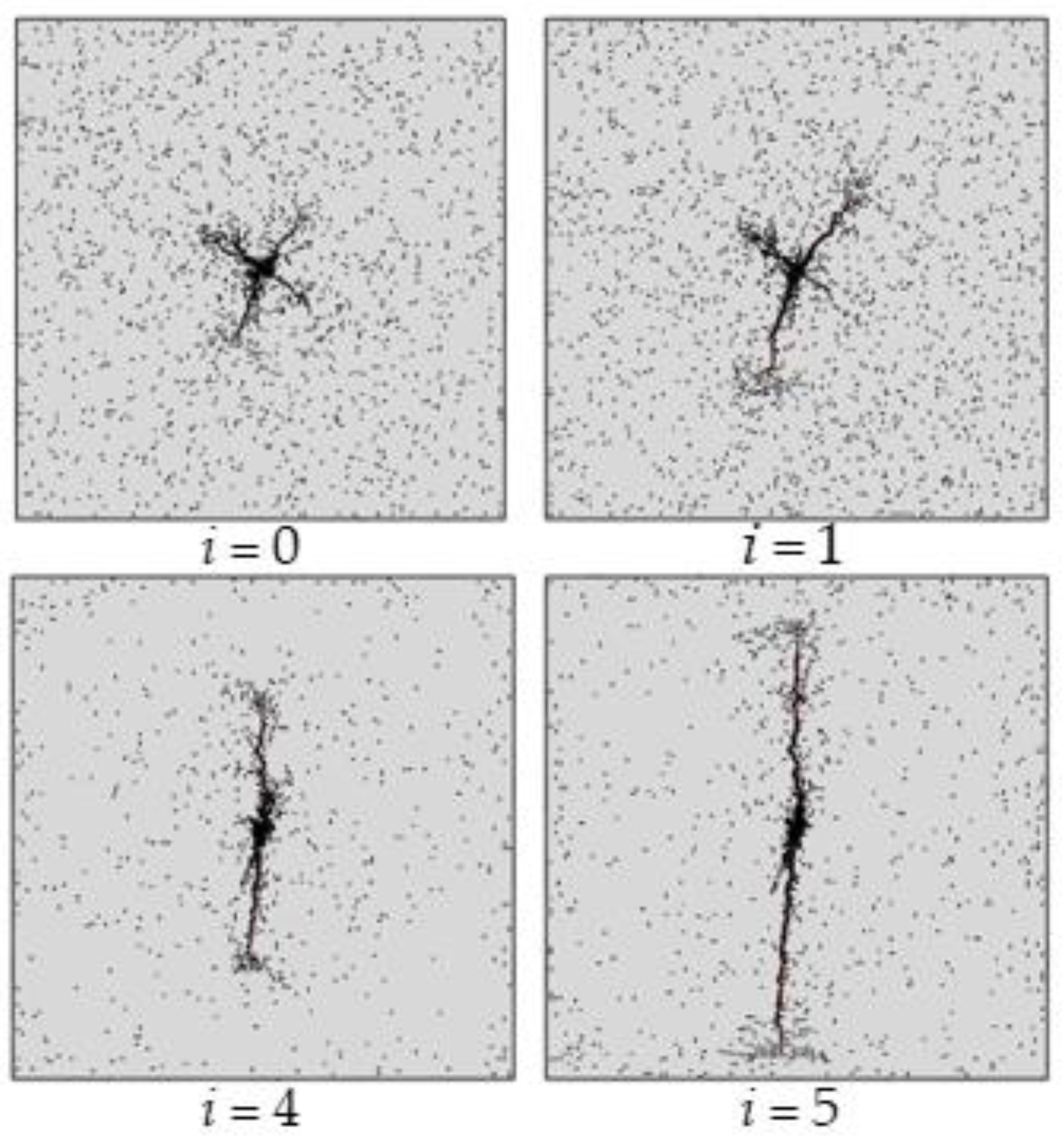
Figure 3 presents the simulated crack propagation morphology under varying horizontal ground stress differences. Observing the figure, it can be seen that when the horizontal stress difference is i = 0 , the crack morphology tends to be complex and expands along the borehole. With an increase in horizontal stress differences i , the crack morphology gradually becomes single and extends along the direction of the maximum horizontal principal stress. Previous studies on crack propagation patterns under different levels of ground stress difference have revealed that under different ground stress conditions, the crack propagation direction is consistent with the maximum principal stress direction. The initiation and propagation of fracturing cracks are mainly affected by the maximum principal tensile stress, see [32,33,34,35]. The research results obtained in this study are consistent with those of previous studies.

4. Application of Finite-Discrete Element Model of Hydraulic Fracturing

4.1. Experimental Protocol

The metamorphic degree of the coal seam affects the coal matrix and its pore structure, which makes the elastic modulus and permeability of the coal seam change [36,37,38]. Different elastic moduli and permeability will show different fracturing results in hydraulic fracturing. In order to explore the evolution law of stress and cracks during hydraulic fracturing under different factors, combined with the buried depth of the mining area where the coal seam is located, the maximum horizontal in situ stress is 1.57 times the minimum horizontal in situ stress. Therefore, the hydraulic fracturing model applies effective in situ stress of 5 MPa in the X-axis direction and 7.85 MPa in the Y-axis direction in the simulation experiments. The specific simulation scheme is shown in Table 3. The first four groups of experiments were used to simulate the evolution of stress and cracks with time in hydraulic fracturing, and the last four groups of experiments were used to simulate the influence of elastic modulus and permeability on the evolution of stress and cracks in hydraulic fracturing. Serial number 4 was the control group for the different elastic modulus and permeability experiments.

4.2. Analysis of the Evolution Law of Stress and Crack with Time in Hydraulic Fracturing

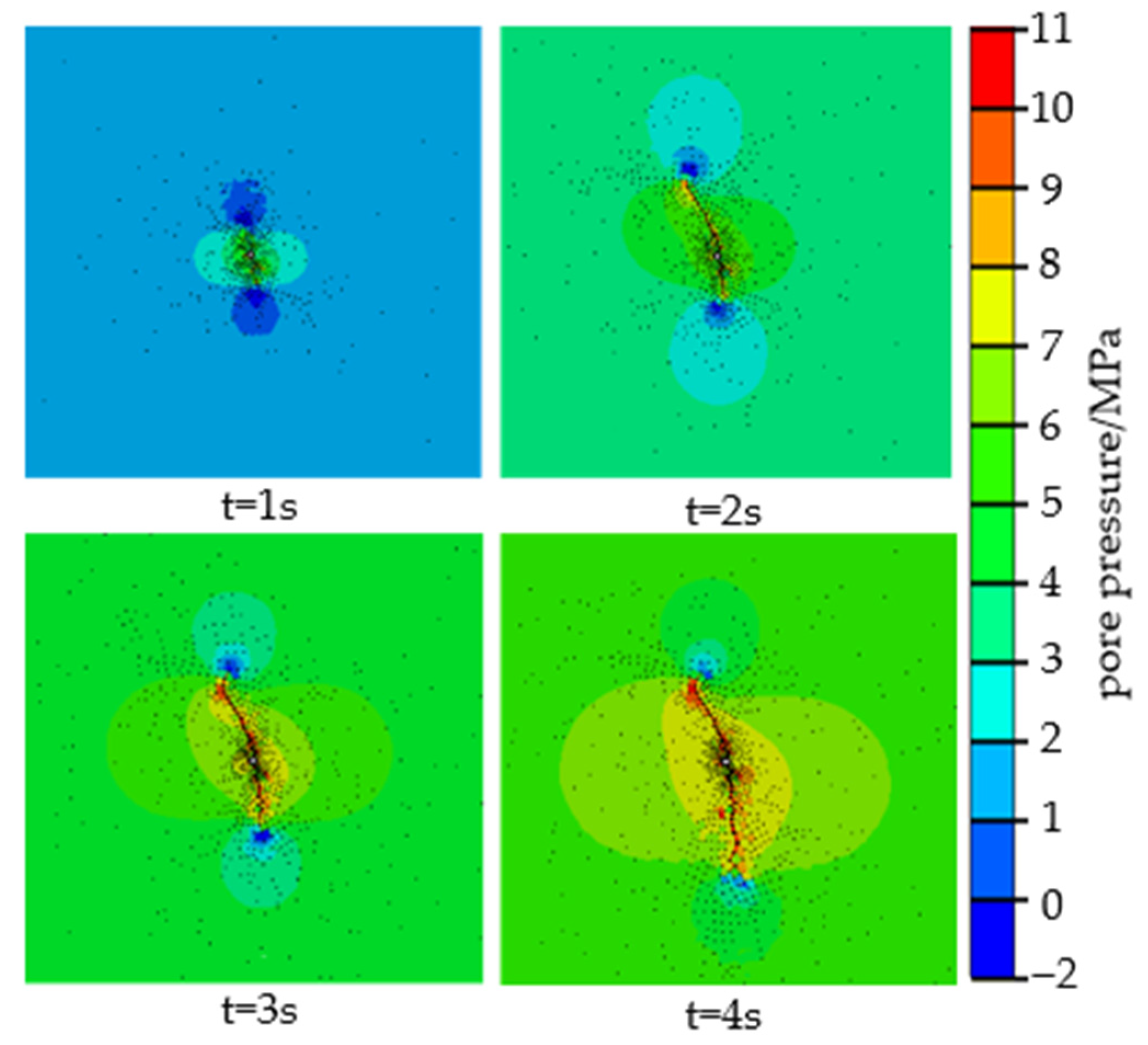
In the process of hydraulic fracturing, stress evolution characteristics determine the direction and shape of crack propagation [39,40,41,42]. Therefore, in order to study the influence of different factors on the stress and crack evolution of hydraulic fracturing, the evolution law of stress and cracks with time should be clarified first. Based on the hydraulic fracturing model, a numerical simulation was carried out based on the No. 1, No. 2, No. 3, and No. 4 experiments in the scheme design, and a pore pressure cloud diagram of crack propagation at different times was obtained, as shown in Figure 4.
It can be seen from Figure 4 that there is no obvious main crack in the initial 1 s of hydraulic fracturing. The stress field around the borehole presents an ellipse with the minimum horizontal stress direction as the long axis direction, and a low pore pressure area is formed in the direction of the maximum horizontal stress. This is because the increase in water injection pressure makes the stress field in the coal seam evolve continuously, and the existing water pressure is not enough to make the low pore pressure area formed by all the crack tips. As the fracturing time progresses, cracks that fail to form a low pore pressure area at their tips cease to expand, whereas cracks that do establish a low pore pressure area undergo further evolution, transitioning into main cracks and continuing their expansion. The farther the main crack expands, the more obvious the principal stress is, and the smaller the low pore pressure area at the tip of the formed crack is. The low pore pressure area at the crack tip formed by stress evolution represents the direction and ability of crack propagation. When the crack propagation encounters a weak surface in the coal reservoir, the smaller the low pore pressure area at the tip is, the more likely it is to deflect or bifurcate, thus promoting the direction of stress evolution to shift. The above analyses show that the crack and stress belong to a mutual feedback mechanism during evolution. The evolution of the stress field affects the pore pressure at the tip of the crack and thus affects the direction of crack expansion. After the crack expands, it acts on the evolution of the stress field to form a new stress field. It can be seen from the pore pressure cloud diagram of crack expansion at 3 s and 4 s that the expansion of the main crack is accompanied by the generation of secondary cracks, and the effective permeability range of fracturing is finally manifested as an elliptical stress concentration area with the main crack as the long axis.
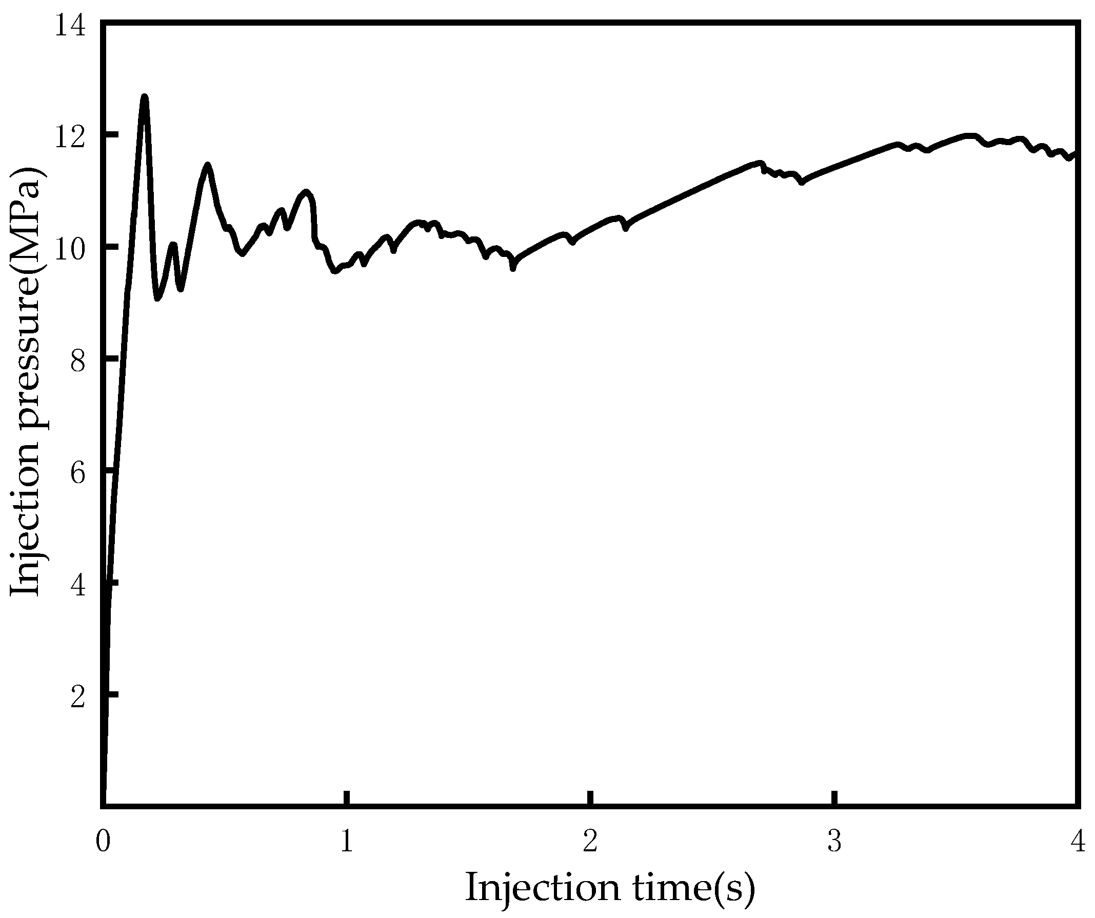
The hydraulic fracturing model simulates the injection time of 4 s to obtain the injection pressure at different times, and draws it into the injection pressure time curve, as shown in Figure 5. With the continuous injection of liquid into the coal, the process of pressure accumulation, followed by coal fracture and then a pressure drop is repeated. Before the coal seam rupture, the pressure in the borehole increases linearly with the injection time. When the pressure reaches the peak value, the coal seam ruptures and the fracturing fluid penetrates the coal seam. Therefore, the first peak pressure in the injection pressure curve corresponds to the fracture pressure of the coal seam. With the continuous extension of cracks, the main influencing factor on injection pressure will change from the fracture toughness of coal to the viscosity of fracturing fluid. In this study, only 4 s of simulation was carried out. As fracturing continues, the increase in the migration distance of the fracturing fluid will lead to an increase in the energy lost by friction, resulting in an increase in the injection pressure.

4.3. Analysis of the Evolution Law of Stress and Crack in Hydraulic Fracturing under Different Elastic Modulus

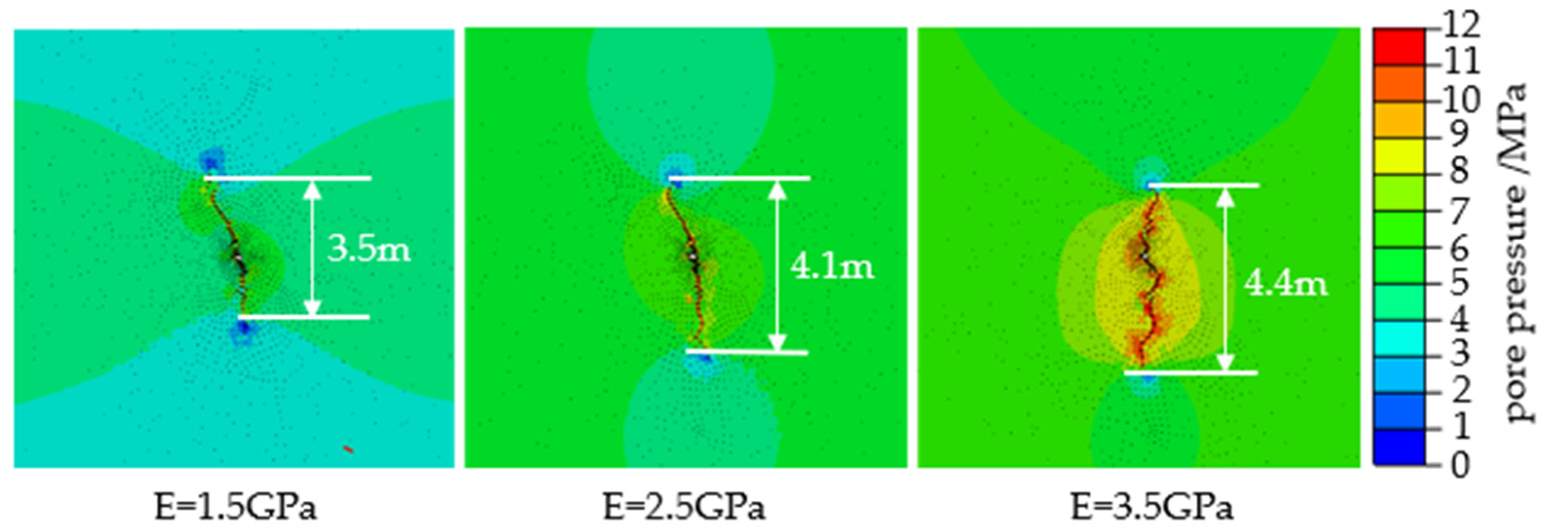
Focusing on the problem of different elastic moduli of coal seams with different metamorphic degrees, based on the hydraulic fracturing model, a numerical simulation was carried out based on the No. 4, No. 5, and No. 6 experiments in the scheme design, and the evolution law of stress and cracks in hydraulic fracturing under different elastic moduli was carried out. In order to facilitate the comparison of the differences in fracturing results under different elastic moduli, the upper threshold of pore pressure in the coal seam was set to 12 MPa, and the lower threshold was set to 0 MPa. The part of the cloud map exceeding 12 MPa is red, and the part below 0 MPa is blue. The simulation results are shown in Figure 6.
According to Figure 6, it is evident that as the elastic modulus increases within the same fracturing duration, the range of pore pressure surrounding the crack steadily expands. Consequently, the effective influence area of hydraulic fracturing continuously enlarges. Moreover, at the crack propagation length, hydraulic fractures formed in high elastic modulus coal seams exhibit greater length, exceeding those formed in low elastic modulus coal seams by an additional 0.9 m. Nevertheless, the impact of elastic modulus on crack propagation length is somewhat limited. The length of hydraulic fractures formed at an elastic modulus of E = 2.5 GPa exceeds those formed at E = 1.5 GPa by only 0.6 m, and the difference in crack propagation length between E = 3.5 GPa and E = 2.5 GPa is merely 0.3 m. Along the crack propagation path, there is little change when the elastic modulus is E < 2.5 GPa. However, at E = 3.5 GPa, not only does the crack propagation path alter, but the crack morphology also becomes more intricate. This is attributed to the higher elastic modulus of coal, resulting in increased stiffness, enhanced plasticity, and a greater likelihood of plastic fracture, thereby forming complex cracks. Consequently, in the hydraulic fracturing process, coal seams with a high elastic modulus not only experience changes in crack propagation path but also exhibit more intricate crack shapes.
The liquid injection pressure at different times simulated under different elastic moduli is drawn into the liquid injection pressure time curve, as shown in Figure 7. The crack initiation pressure of E = 1.5 GPa is 11.10 MPa, E = 2.5 GPa is 12.67 MPa, and E = 3.5 GPa is 13.85 MPa. Therefore, the increase in elastic modulus will not only increase the crack initiation pressure of the coal seam but will also reduce the time required for crack initiation. At the same time, the overall injection pressure required for crack propagation in the coal seam will also increase. Comparing the fluctuation degree of liquid injection pressure time curve with different elastic moduli, the fluctuation in the liquid injection pressure curve under high elastic modulus is more complicated. From the previous analysis of Figure 6, it could be seen that the high elastic modulus formed more complex cracks. In the field of hydraulic fracturing, the complexity of fracturing cracks can be preliminarily judged by the injection pressure time curve, and then the fracturing effect can be preliminarily evaluated.

4.4. Analysis of the Evolution Law of Stress and Crack in Hydraulic Fracturing under Different Permeability

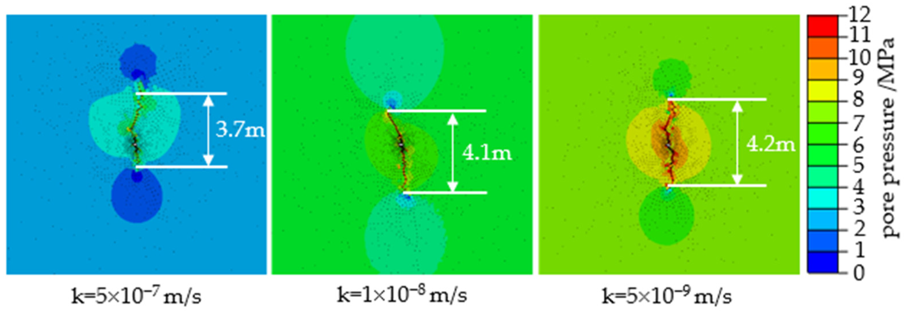
The permeability of the coal seam is a key parameter in the evaluation of the coalbed methane selection area, which is very important for the development of coalbed methane [43]. The permeability of the coal seam is complex and changeable due to the influence of temperature, ground stress, and other factors [44,45]. In order to explore the influence of permeability on hydraulic fracturing, the hydraulic fracturing model was used to carry out a numerical simulation based on the No. 4, No. 7, and No. 8 experiments in the scheme design, and the stress and crack evolution law of hydraulic fracturing under different permeability was studied. To compare the differences in fracturing results under different permeability, the upper threshold of coal seam pore pressure was set to 12 MPa, and the lower threshold was set to 0 MPa. The part of the cloud map exceeding 12 MPa is red, and the part below 0 MPa is blue. The simulation results are shown in Figure 8.
From Figure 8, it is evident that as permeability decreases, the range of pore pressure surrounding the fractured crack steadily increases. This observation suggests that coal seams with low permeability are more favorable for hydraulic fracturing. Furthermore, at the crack propagation length, fractures formed in low permeability coal seams exhibit greater length, surpassing those formed in high permeability coal seams by an additional 0.5 m. However, the impact of permeability on crack length is relatively limited. The crack length formed at a permeability coefficient of k = 1 × 10⁻⁸ m/s exceeds that at k = 5 × 10⁻⁷ m/s by only 0.4 m, and the difference between the crack length at k = 5 × 10⁻⁹ m/s and k = 1 × 10⁻⁸ m/s is a mere 0.1 m. Hence, when the permeability coefficient is k < 1 × 10⁻⁸ m/s, the decrease in permeability leads to a gradual increase in crack length. Regarding crack morphology, fractures formed at a permeability coefficient of k = 5 × 10⁻⁹ m/s exhibit greater complexity, whereas those at k = 5 × 10⁻⁷ m/s and k = 1 × 10⁻⁸ m/s display relatively simpler patterns. Nevertheless, it is important to note that changes in permeability can alter the propagation path of fracturing cracks.
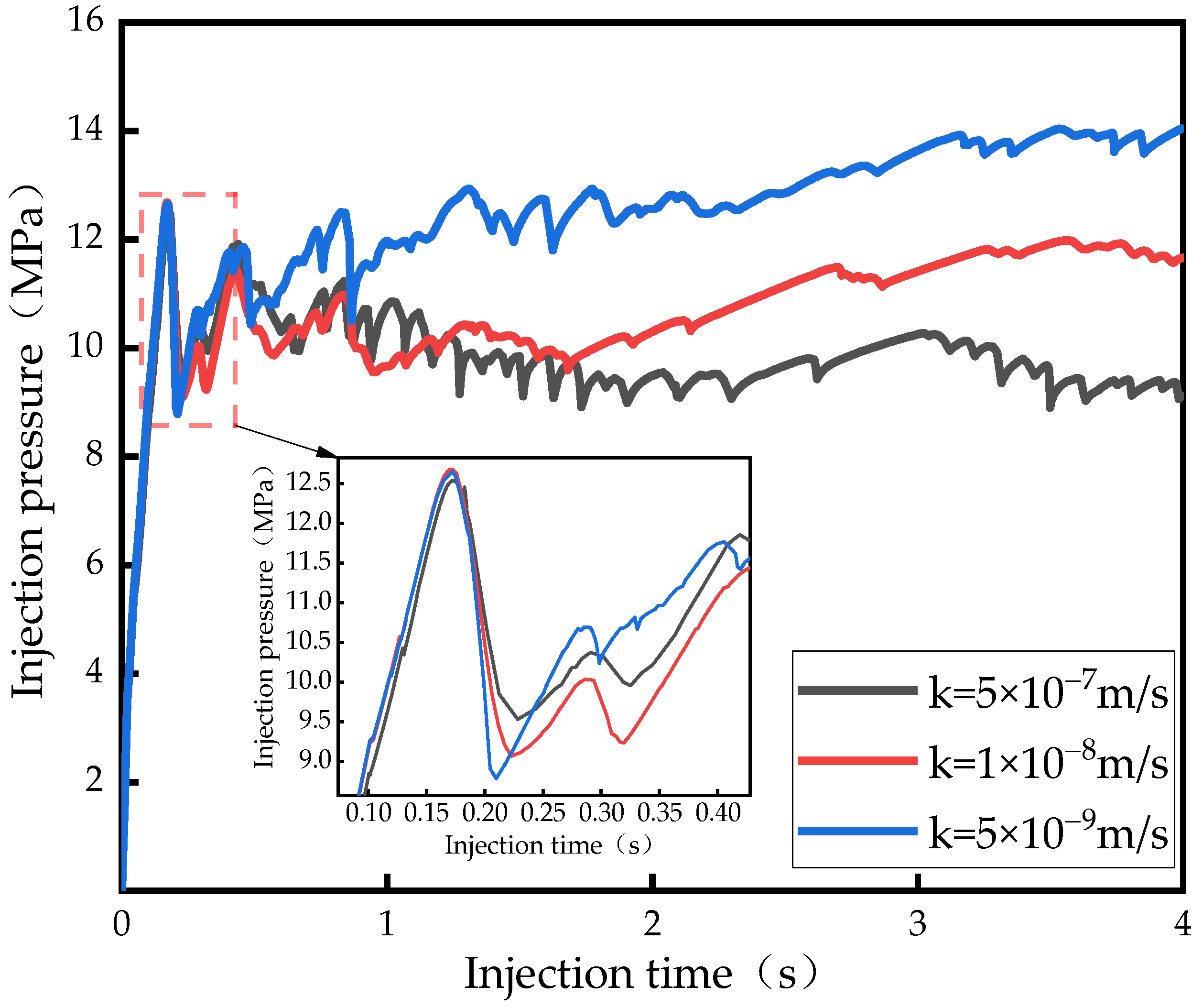
The injection pressure of different permeability in 4 s is drawn into the injection pressure time curve, as shown in Figure 9. The crack initiation pressure of k = 5 × 10⁻⁷ m/s is 12.53 MPa, k = 1 × 10⁻⁸ m/s is 12.67 MPa, and k = 5 × 10⁻⁹ m/s is 12.65 MPa. Therefore, the change of permeability had little effect on the initiation pressure and initiation time of the coal seam. With the continuous injection of liquid, the injection pressure exhibits a rapid increase in low permeability coal seams, whereas in high permeability coal seams, the injection pressure remains relatively stable, showing an overall downward trend. This is because when the injection rate of the fracturing fluid is constant, the permeability of the coal seam directly determines the degree of filtration of the fracturing fluid. The greater the permeability is, the greater the degree of filtration of the fracturing fluid is, resulting in less fracturing fluid really being used for fracturing, so that the injection pressure is reduced accordingly, and the crack expansion effect becomes worse.
By comparing the stress and crack evolution laws of hydraulic fracturing under different elastic moduli and permeability, it can be concluded that the mutual feedback relationship between crack evolution and stress field evolution is transient. This relationship is only related to the current crack state and will not be changed by other factors, and the direction of crack propagation and stress evolution is obviously consistent. Therefore, on the engineering side, changes in the stress field of the coal seam can be monitored by implementing a stress monitoring area, and the effective fracturing range can be accurately predicted by means of transient electromagnetic and micro-seismic techniques.

5. Conclusions

In this paper, a two-dimensional numerical model of hydraulic fracturing was established by using the finite-discrete element method (FDEM), and the damage evolution equation of coal required by the simulation method was derived using the theory of fracture mechanics. In order to verify the feasibility of the model, the evolution law of stress and cracks with time in hydraulic fracturing was analyzed, and hydraulic fracturing simulations of coal seams with different elastic moduli and permeability were carried out. The following conclusions were drawn:
(1) Crack and stress evolution during hydraulic fracturing belong to mutual feedback mechanisms. The farther a crack expands, the more obvious the effect of being held by main stress, and finally an elliptical effective permeability range is formed with the crack as the long axis;
(2) A higher elastic modulus in the coal seam will make the crack extension length greater, but the increase in elastic modulus has a limited effect on the crack length. A coal seam with a high elastic modulus is more likely to form complex fissures, resulting in a larger range of permeability enhancement. As the elastic modulus of the coal seam increases, the crack initiation pressure of the coal seam becomes higher and the crack initiation time becomes shorter;
(3) A lower permeability in the coal seam is more favorable to hydraulic fracturing, and the change of permeability affects the crack propagation morphology, but the effects on crack initiation pressure and crack initiation time are not obvious;
(4) Through the comparative analysis of stress and crack evolution laws of hydraulic fracturing under different factors, it is concluded that the direction of stress evolution is obviously consistent with the direction of crack expansion. The accurate prediction of fracturing range in this field can be realized by implementing stress monitoring areas and combining them with micro-seismic monitoring techniques.

Author Contributions

Conceptualization, S.Y.; methodology, S.Y. and N.X.; validation, S.Y. and N.X.; formal analysis, S.Y., N.X. and X.Z.; investigation, N.X. and X.Z.; writing—original draft preparation, S.Y. and N.X.; writing—review and editing, S.Y. and N.X.; visualization, N.X. and X.Z.; supervision, S.Y.; project administration, S.Y.; funding acquisition, S.Y. All authors have read and agreed to the published version of the manuscript.

Funding

This study was funded by the Open Fund of the State Key Laboratory of Gas Disaster Detecting, Preventing and Emergency Controlling, No. 2022SKLKF05.

Institutional Review Board Statement

Not applicable.

Informed Consent Statement

Not applicable.

Data Availability Statement

Not applicable.

Acknowledgments

First of all, we acknowledge the editors and reviewers for their valuable comments; secondly, we are grateful for the help of the fund from the State Key Laboratory of Gas Disaster Detecting, Preventing and Emergency Controlling; finally, we appreciate the authors of all references for their achievements that bring us new ideas.

Conflicts of Interest

The authors declare no conflict of interest.

References

  1. Jia, A.; Cheng, G.; Chen, W.; Li, Y. Forecast of natural gas supply and demand in China under the background of ?Dual Carbon Targets? Pet. Explor. Dev. 2023, 50, 492–504. [Google Scholar] [CrossRef]
  2. Tao, S.; Chen, S.D.; Pan, Z.J. Current status, challenges, and policy suggestions for coalbed methane industry development in China: A review. Energy Sci. Eng. 2019, 7, 1059–1074. [Google Scholar] [CrossRef] [Green Version]
  3. Wei, J.; Niu, C.-H. How does institutional support affect the coalbed methane industry? Front. Energy Res. 2023, 10, 1087984. [Google Scholar] [CrossRef]
  4. Li, R.; Li, G. Coalbed Methane Industry Development Framework and Its Limiting Factors in China. Geofluids 2022, 2022, 8336315. [Google Scholar] [CrossRef]
  5. Peng, T.; Chen, Y.; Wang, L.; Ma, D.; Li, G.; Li, W.; Zheng, C.; Ji, Y.; Ma, Z.; Hui, P.; et al. Mechanism of Methane Adsorption/Desorption in Low-Rank Vitrain and Durain Coal Affected by Pore Structure and Wettability: A Case Study in Dafosi Area, South Ordos Basin, China. Energies 2022, 15, 5094. [Google Scholar] [CrossRef]
  6. Zhao, D.; Guo, Y.; Wang, G.; Guan, X.; Zhou, X.; Liu, J. Fractal Analysis and Classification of Pore Structures of High-Rank Coal in Qinshui Basin, China. Energies 2022, 15, 6766. [Google Scholar] [CrossRef]
  7. Li, F.; Liu, H.W.; Wang, C.C.; Sun, R.C.; Xiang, G.Y.; Ren, B.R.; Wang, G.H. Stress Relief and Permeability Enhancement with Hydraulic Fracturing in Overlying Key Strata of Deep and Soft Coal Seams. ACS Omega 2023, 8, 12183–12193. [Google Scholar] [CrossRef]
  8. Zhang, C.; Wang, E.; Xu, J.; Peng, S. A new method for coal and gas outburst prediction and prevention based on the fragmentation of ejected coal. Fuel 2021, 287, 119493. [Google Scholar] [CrossRef]
  9. Zhang, Y.; Li, Q.; Hu, Q.; Zhai, C.; Song, M.; Xu, J.; Deng, Y.; Liu, P.; Sun, Y.; Shi, J.; et al. Pore wetting process characterization of Equal-Sized granular coals by using LF-NMR technology. Fuel 2022, 313, 122670. [Google Scholar] [CrossRef]
  10. Chang, Y.; Yao, Y.; Liu, D.; Liu, Y.; Cui, C.; Wu, H. Behavior and mechanism of water imbibition and its influence on gas permeability during hydro-fracturing of a coalbed methane reservoir. J. Pet. Sci. Eng. 2022, 208, 109745. [Google Scholar] [CrossRef]
  11. Li, P.; Wang, J.; Liang, W.; Sun, R. An Analytical and Numerical Analysis for Hydraulic Fracture Propagation through Reservoir Interface in Coal-Measure Superimposed Reservoirs. Sustainability 2023, 15, 4597. [Google Scholar] [CrossRef]
  12. Liu, H.; Li, X.; Yu, Z.; Tan, Y.; Ding, Y.; Chen, D.; Wang, T. Influence of hole diameter on mechanical properties and stability of granite rock surrounding tunnels. Phys. Fluids 2023, 35, 064121. [Google Scholar] [CrossRef]
  13. Zheng, C.S.; Jiang, B.Y.; Xue, S.; Chen, Z.W.; Li, H. Coalbed methane emissions and drainage methods in underground mining for mining safety and environmental benefits: A review. Process Saf. Environ. Prot. 2019, 127, 103–124. [Google Scholar] [CrossRef]
  14. Liang, W.; Yang, J.; Lian, H.; Wang, Z.; Shen, W. Modelling ductile failure of coals in hydraulic fracturing based on the constitutive equations of cohesive cracks. J. China Coal Soc. 2019, 44, 263–270. [Google Scholar] [CrossRef]
  15. Huang, L.; Li, B.; Wang, B.; Zhang, J. Effects of coal bedding dip angle on hydraulic fracturing crack propagation. Geomech. Geophys. Geo-Energy Geo-Resour. 2023, 9, 30. [Google Scholar] [CrossRef]
  16. Jia, J.; Wang, D.; Li, B. Study on influencing factors of effective fracturing radius of hydraulic fracturing. J. Saf. Sci. Technol 2022, 18, 58–64. [Google Scholar] [CrossRef]
  17. Lu, Y.; Huang, S.; Ge, Z.; Zhou, Z.; Song, Z. Fluid-driven cracking behavior of coal with prefabricated plane: A particle-based hydro-mechanical coupled numerical investigation. Theor. Appl. Fract. Mech. 2023, 124, 103825. [Google Scholar] [CrossRef]
  18. Ma, Y.; Wang, D.; Zheng, Y. Influence of the bedding plane on the propagation of multiple hydraulic fractures. Front. Earth Sci. 2023, 10, 1077652. [Google Scholar] [CrossRef]
  19. Li, Y.; Liu, J.; Yu, Q. Patterns of Influence of Parallel Rock Fractures on the Mechanical Properties of the Rock–Coal Combined Body. Sustainability 2022, 14, 13555. [Google Scholar] [CrossRef]
  20. Fu, S.; Hou, B.; Xia, Y.; Chen, M.; Wang, S.; Tan, P. The study of hydraulic fracture height growth in coal measure shale strata with complex geologic characteristics. J. Pet. Sci. Eng. 2022, 211, 110164. [Google Scholar] [CrossRef]
  21. Jia, Q.; Liu, D.; Cai, Y.; Fang, X.; Li, L. Petrophysics characteristics of coalbed methane reservoir: A comprehensive review. Front. Earth Sci. 2021, 15, 202–223. [Google Scholar] [CrossRef]
  22. Li, S.; Tang, D.; Pan, Z.; Xu, H.; Tao, S.; Liu, Y.; Ren, P. Geological conditions of deep coalbed methane in the eastern margin of the Ordos Basin, China: Implications for coalbed methane development. J. Nat. Gas Sci. Eng. 2018, 53, 394–402. [Google Scholar] [CrossRef]
  23. Liu, D.; Jia, Q.; Cai, Y.; Gao, C.; Qiu, F.; Zhao, Z.; Chen, S. A new insight into coalbed methane occurrence and accumulation in the Qinshui Basin, China. Gondwana Res. 2022, 111, 280–297. [Google Scholar] [CrossRef]
  24. Liu, S.M.; Sun, H.T.; Zhang, D.M.; Yang, K.; Li, X.L.; Wang, D.K.; Li, Y.N. Experimental study of effect of liquid nitrogen cold soaking on coal pore structure and fractal characteristics. Energy 2023, 275, 127470. [Google Scholar] [CrossRef]
  25. Liu, H. Wing-crack initiation angle: A new maximum tangential stress criterion by considering T-stress. Eng. Fract. Mech. 2018, 199, 380–391. [Google Scholar] [CrossRef]
  26. Wang, Z.; Zhang, Q.; Zhang, W. A novel collaborative study of abnormal roof water inrush in coal seam mining based on strata separation and wing crack initiation. Eng. Fail. Anal. 2022, 142, 106762. [Google Scholar] [CrossRef]
  27. Lisjak, A.; Kaifosh, P.; He, L.; Tatone, B.S.A.; Mahabadi, O.K.; Grasselli, G. A 2D, fully-coupled, hydro-mechanical, FDEM formulation for modelling fracturing processes in discontinuous, porous rock masses. Comput. Geotech. 2017, 81, 1–18. [Google Scholar] [CrossRef]
  28. Yan, C.Z.; Guo, H.; Tang, Z.C. Three-dimensional continuous-discrete pore-fracture mixed seepage model and hydro-mechanical coupling model to simulate hydraulic fracturing. J. Pet. Sci. Eng. 2022, 215, 110510. [Google Scholar] [CrossRef]
  29. Yan, C.Z.; Xie, X.; Ren, Y.H.; Ke, W.H.; Wang, G. A FDEM-based 2D coupled thermal-hydro-mechanical model for multiphysical simulation of rock fracturing. Int. J. Rock Mech. Min. Sci. 2022, 149, 104964. [Google Scholar] [CrossRef]
  30. Wang, X.; Wang, E.; Liu, X.; Li, N.; Zhou, X. Three-point-bending test of crack propagation and fracture parameters of coal specimens. Chin. J. Rock Mech. Eng 2021, 40, 690–702. [Google Scholar] [CrossRef]
  31. Wang, S.; Tan, F.; Lv, J.; You, M. Discrete element numerical simulation of hydraulic fracturing based on Hoek-Brown strength criterion. Eng. J. Wuhan Univ. 2021, 54, 290–297. [Google Scholar] [CrossRef]
  32. Yan, C.; Zheng, H.; Sun, G.; Ge, X. Effect of in-situ stress on hydraulic fracturing based on FDEM-Flow. Rock Soil Mech. 2016, 37, 237–246. [Google Scholar] [CrossRef]
  33. Liu, C.; Li, S.G.; Qin, S.; Yang, S.G. Research and Application of Influences of Lateral Pressure Coefficients on the Extension Angle of Coal Cracks. Math. Probl. Eng. 2016, 2016, 3068347. [Google Scholar] [CrossRef] [Green Version]
  34. Wang, H.; Gong, W.; Yuan, G.; Wang, X.; Zhao, J.; Su, Y.; Wang, Y. Effect of In-Situ Stress on Hydraulic Fracturing of Tight Sandstone Based on Discrete Element Method. Energies 2022, 15, 5620. [Google Scholar] [CrossRef]
  35. Zhang, X.; Si, G.; Bai, Q.; Xiang, Z.; Li, X.; Oh, J.; Zhang, Z. Numerical simulation of hydraulic fracturing and associated seismicity in lab-scale coal samples: A new insight into the stress and aperture evolution. Comput. Geotech. 2023, 160, 105507. [Google Scholar] [CrossRef]
  36. Feng, Z.; Yang, Y.; Niu, W.; Zhao, Y.; Wan, Z.; Yao, Y. Permeability and meso-structure evolution of coking coal subjected to long-term exposure of triaxial stresses and high-pressure nitrogen. Geomech. Geophys. Geo-Energy Geo-Resour. 2020, 6, 41. [Google Scholar] [CrossRef]
  37. Shao, P.; Wang, X.; Song, Y.; Li, Y. Study on the characteristics of matrix compressibility and its influence factors for different rank coals*. J. Nat. Gas Sci. Eng. 2018, 56, 93–106. [Google Scholar] [CrossRef]
  38. Tang, S.; Tang, D.; Xu, H.; Tao, S.; Li, S.; Geng, Y. Geological mechanisms of the accumulation of coalbed methane induced by hydrothermal fluids in the western Guizhou and eastern Yunnan regions. J. Nat. Gas Sci. Eng. 2016, 33, 644–656. [Google Scholar] [CrossRef] [Green Version]
  39. Li, X.; Zhang, X.; Shen, W.; Zeng, Q.; Chen, P.; Qin, Q.; Li, Z. Research on the Mechanism and Control Technology of Coal Wall Sloughing in the Ultra-Large Mining Height Working Face. Int. J. Environ. Res. Public Health 2023, 20, 868. [Google Scholar] [CrossRef]
  40. Llanos, E.M.; Jeffrey, R.G.; Hillis, R.; Zhang, X. Hydraulic fracture propagation through an orthogonal discontinuity: A laboratory, analytical and numerical study. Rock Mech. Rock Eng. 2017, 50, 2101–2118. [Google Scholar] [CrossRef]
  41. Zhang, J.; Li, X.; Qin, Q.; Wang, Y.; Gao, X. Study on overlying strata movement patterns and mechanisms in super-large mining height stopes. Bull. Eng. Geol. Environ. 2023, 82, 142. [Google Scholar] [CrossRef]
  42. Zhang, L.; Shen, W.; Li, X.; Wang, Y.; Qin, Q.; Lu, X.; Xue, T. Abutment Pressure Distribution Law and Support Analysis of Super Large Mining Height Face. Int. J. Environ. Res. Public Health 2023, 20, 227. [Google Scholar] [CrossRef] [PubMed]
  43. Yang, Z.; Li, Y.; Qin, Y.; Sun, H.; Zhang, P.; Zhang, Z.; Wu, C.; Li, C.; Chen, C. Development unit division and favorable area evaluation for joint mining coalbed methane. Pet. Explor. Dev. Online 2019, 46, 583–593. [Google Scholar] [CrossRef]
  44. Liu, S.; Wang, D.; Yin, G.; Li, M.; Li, X. Experimental study on the microstructure evolution laws in coal seam affected by temperature impact. Rock Mech. Rock Eng. 2020, 53, 1359–1374. [Google Scholar] [CrossRef]
  45. Zhang, L.; Huang, M.; Xue, J.; Li, M.; Li, J. Repetitive mining stress and pore pressure effects on permeability and pore pressure sensitivity of bituminous coal. Nat. Resour. Res. 2021, 30, 4457–4476. [Google Scholar] [CrossRef]
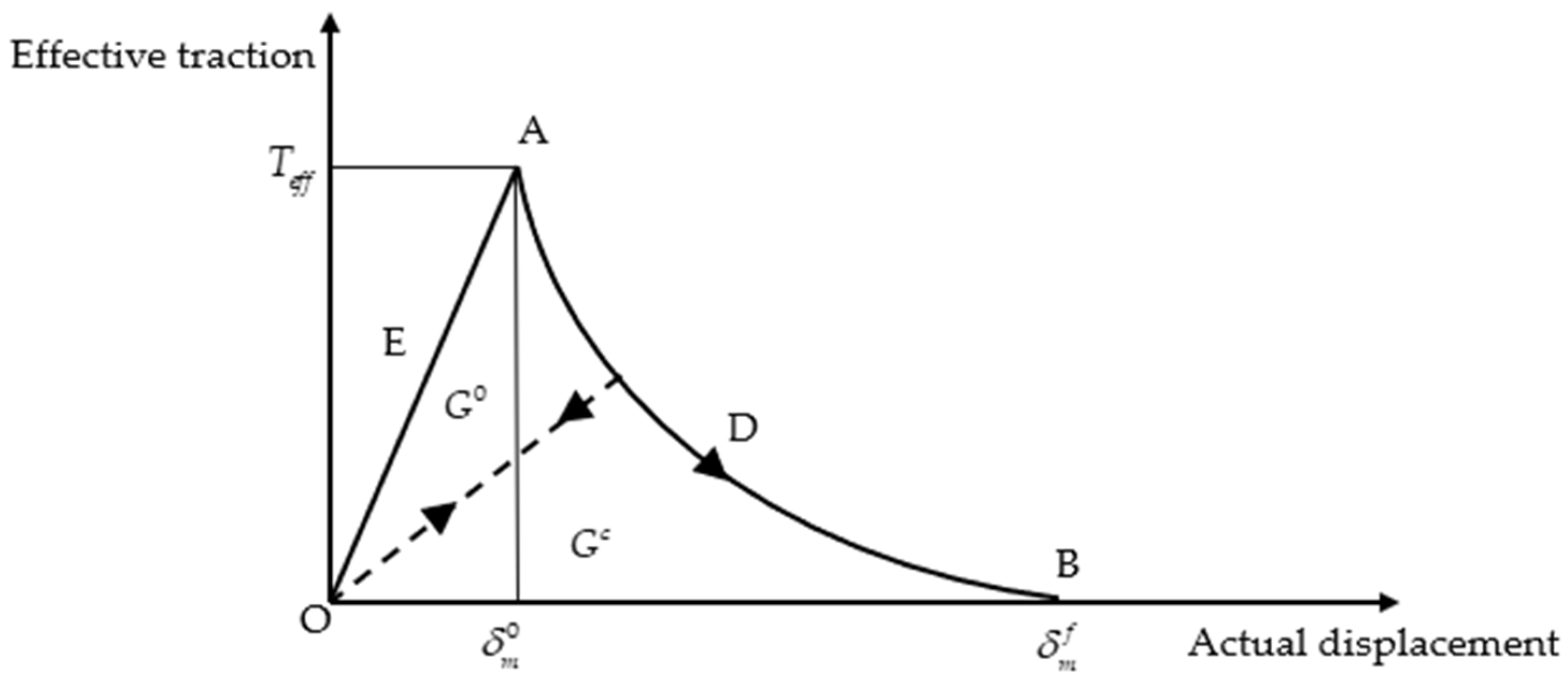
Figure 1. Constitutive relation curve of cohesive element.
Sustainability 15 11351 g001
Figure 2. Hydraulic fracturing model.
Sustainability 15 11351 g002
Figure 3. Crack propagation morphology under different ground stress difference.
Sustainability 15 11351 g003
Figure 4. Pore pressure figure of crack propagation at different times.
Sustainability 15 11351 g004
Figure 5. Injection pressure time curve.
Sustainability 15 11351 g005
Figure 6. Pore pressure figure of crack propagation with different elastic modulus at 4 s.
Sustainability 15 11351 g006
Figure 7. Injection pressure time curve with different elastic moduli.
Sustainability 15 11351 g007
Figure 8. Pore pressure figure of crack propagation with different permeability at 4 s.
Sustainability 15 11351 g008
Figure 9. Injection pressure time curve with different permeability.
Sustainability 15 11351 g009
Table 1. Partial parameter of the model.
ModelsParametersTakes Values
Entity unitElasticity modulus (GPa)2.5
Poisson ratio0.32
Permeability coefficient (m/s)10−8
Porosity 0.1
Cohesive elementI type fracture energy (N/m)49.58
II type fracture energy (N/m)194.3
Normal stiffness (GPa)2.5
Tangential stiffness (GPa)2.5
η (B-K) Guidelines2.54
FluidsViscosity (Pa s)0.001
Density (kg/m3)1000
Injection flow rate (m3/s)0.003
Table 2. Calculation results of rupture pressure.
Number σ H (MPa) σ h (MPa) i (MPa)Simulation Results (MPa)HB Criterion Results (MPa)Error (%)
155014.8914.940.33
265114.1514.180.21
375213.3413.410.52
485312.5812.650.55
595411.8111.870.51
6105511.0711.120.45
Table 3. Scheme design of hydraulic fracturing simulation.
NumberModulus of Elasticity (GPa)Permeability Coefficient (m/s)Fracturing Time (s)
12.510−81
22.510−82
32.510−83
42.510−84
51.510−84
63.510−84
72.55 × 10−74
82.55 × 10−94
Note: The permeability of low, medium, and high coal bodies correspond to permeability coefficients k = 5 × 10⁻⁹, k = 10−8, k = 5 × 10⁻⁷ m/s, respectively; the elastic modulus of low, medium and high coal bodies correspond to E = 1.5, E = 2.5 and E = 3.5 GPa, respectively.
Disclaimer/Publisher’s Note: The statements, opinions and data contained in all publications are solely those of the individual author(s) and contributor(s) and not of MDPI and/or the editor(s). MDPI and/or the editor(s) disclaim responsibility for any injury to people or property resulting from any ideas, methods, instructions or products referred to in the content.