Abstract
To enhance the reliability and flexibility of DC microgrids (DCMGs), this paper presents a decentralized power flow control strategy (PFCS) by using the transition operation modes. The transition operation modes are introduced as an effective communication method among power units, eliminating the use of additional digital communication links (DCLs) for the purpose of ensuring the power balance as well as the voltage regulation even under uncertain conditions. During the transition operation modes, the power unit which transmits the information shifts the DC-link voltage level, and the power unit which receives the information continuously monitors the DC-link voltage with predetermined time. When uncertain conditions occur in a particular power unit, this power unit triggers the transition operation modes to send this information to all power units in the DCMG system. The proposed PFCS can maintain the DC-link voltage at the nominal value for steady-state conditions both in the grid-connected mode and islanded mode. Moreover, the proposed PFCS significantly enhances the overall reliability of the decentralized DCMG system by effectively addressing several uncertainties stemmed from electricity price fluctuations, grid availability, battery state-of-charge (SOC) levels, and wind power variations. The scalability of the DCMG system is also demonstrated by incorporating an electric vehicle (EV) unit as an additional energy storage system (ESS). The EV unit seamlessly cooperates with the existing battery unit, functioning as additional ESS to regulate the DC-link voltage when the battery SOC level is low. Simulation and experimentation results under various conditions demonstrate the effectiveness of the proposed PFCS.
1. Introduction
The global energy infrastructure is undergoing a transformation, driven by the need for sustainable and resilient power systems. As traditional centralized power generation models face challenges of efficiency, reliability, and environmental impact, the demand for decentralized energy solutions attracts worldwide attention from researchers. In this context, microgrids have emerged as a promising concept that offers a new paradigm for efficient and flexible power distribution and management. A microgrid, defined as a localized and self-contained power system, provides a reliable and resilient electricity supply. In general, the microgrid integrates various distributed energy resources (DERs), renewable energy, energy storage systems (ESSs), and controllable loads [1]. As the world’s energy situation keeps changing, microgrids are becoming increasingly important in driving the shift toward a sustainable and reliable energy future.
In the microgrid system, the DC microgrid (DCMG) has gained significant attention as a promising solution to realize efficient and sustainable power distribution systems. The DCMG system offers several advantages over the AC microgrid system because the issue regarding the synchronization of distributed generators, inrush currents caused by transformers, reactive power flow, harmonic currents, and three-phase unbalance does not exist in the DCMG system [2,3,4]. Furthermore, DCMG offers easy integration for DC energy sources such as photovoltaics (PV), fuel cells, and ESSs like batteries or supercapacitors [5,6].
In general, the DCMG system operation can be categorized into two modes: the grid-connected mode and islanded mode, depending on the availability of the main grid [7]. In the grid-connected mode, the utility grid primarily coordinates the exchange power in the DCMG to achieve power balance as well as voltage regulation. On the other hand, in the islanded mode, the power balance of the DCMG is maintained through a coordinated operation of specific power units, such as distributed generators (DGs) and ESSs. In the grid-connected mode, optimizing the cost of power consumption in a DCMG is a significant concern. Various methods such as time-of-use pricing (TOU), real-time pricing (RTP), and stepwise power tariff (SPT) are used worldwide to calculate electricity bills [8,9,10,11]. To optimize the power consumption cost of a DCMG system, previous studies have considered the electricity price change of the utility grid [12,13,14].
In terms of communication links, the DCMG control methods can be categorized as centralized control, distributed control, and decentralized control. The centralized control uses a central controller to determine the proper operation modes of each power unit by communicating with all power units through digital communication links (DCLs) [15]. In contrast, the distributed control also utilizes DCLs to collect data from adjacent power units without using the central controller. In this approach, each power unit independently determines its operation mode by considering data collected from its surroundings [16]. On the other hand, the decentralized control operates without the use of DCLs. In this scheme, the DCMG system autonomously maintains power balance by relying solely on local measurements of each unit [17,18]. The absence of DCLs in the decentralized control eliminates communication delays and simplifies system installation, thereby enhancing the system’s scalability and flexibility [19]. The elimination of DCLs also has other potential benefits such as lower implementation costs and less dependency on communication systems, which can increase overall reliability and robustness [19,20,21]. Furthermore, the DCMG’s vulnerability to cybersecurity threats may also be decreased, and the effort for maintenance and troubleshooting is reduced, which can potentially lead to faster problem resolution [21,22].
In a decentralized control scheme, the operation modes of each power unit in a DCMG system are determined using the DC-link voltage as a key indicator [23]. When there is surplus power in the DCMG, the DC-link voltage increases. On the contrary, a deficit of power in the DCMG leads to a decrease in the DC-link voltage. To enable power sharing among power sources in the DCMG system, voltage-based droop control methods have been introduced in the study [24]. These methods present the implementation of a virtual resistor to achieve the power balance of each converter in the DCMG system. Voltage/current (V/I) or voltage/power (V/P) characteristics are commonly used in the droop control method for the decentralized DCMG to achieve not only voltage regulation but also power balance [25].
Despite the effective power-sharing characteristic of the droop control, it still has the drawback of DC-link voltage deviation [26]. This deviation in DC-link voltage impacts the delivered power to the load. A significant deviation affects power accuracy, while even a slight deviation may influence power-sharing precision [27]. To overcome this issue, a voltage restoration scheme for a decentralized DCMG is presented in [28], in which the DC-link voltage is maintained at a constant value by injecting or absorbing power. For optimal power-sharing, another study successfully implements the DC-link voltage controller in the centralized and distributed control schemes [29,30]. In these schemes, the DC-link voltage controller should be implemented by at least one power unit in every operation mode of the DCMG.
Aside from the DC voltage deviation, another concern for a reliable decentralized DCMG operation is to carefully manage the battery state-of-charge (SOC) level to avoid faster battery degradation [31]. It is imperative to ensure that the battery operates primarily at high SOC levels for the extension of its lifespan. In the study [32], the low SOC level is only used for certain emergency operations to increase the reliability of DCMG operations. In addition to the battery SOC management, the reliability of the DCMG can be further improved by separately considering the electrical loads as non-critical and critical loads with different priorities [33]. Numerous studies in the field of microgrids have emphasized the importance of maintaining critical loads as well as improving the resilience and survivability of critical loads [34]. Motivated by these concerns, the battery SOC levels will be categorized according to the respective significance in this paper. During periods of low SOC levels, only critical loads are supplied based on the given priority. In this case, non-critical loads are subject to load shedding to achieve high resilience and reliability for the microgrid operation.
To enhance the reliability and optimize the operation of a microgrid system, this paper presents a power flow control scheme (PFCS) for a decentralized DCMG system. The transition operation modes are utilized in the proposed scheme to transmit the information on the DCMG system to other power units without the use of additional DCLs. This is achieved by continuously monitoring the DC-link voltage value in all power units. The DCMG system considered in this study consists of a utility grid unit, battery unit, wind turbine unit, and load units. In the grid-connected mode, the DC-link voltage control method is employed by the utility grid unit. On the other hand, in the islanded mode, the battery and wind turbine units alternate the regulation of the DC-link voltage to the nominal value. In the proposed PFCS, various factors such as the generation power of the wind turbine unit, battery SOC level, grid availability, load demand, and electricity price conditions are considered to develop an overall control strategy for the decentralized DCMG system. In addition, the scalability issue of the DCMG system is also studied by considering an electric vehicle (EV) unit as an additional ESS in the DCMG system. The contribution of the proposed method is to enhance the reliability and optimize the operation of the DCMG system without using the DCLs for significantly reduced system price. The PFCS is proposed to achieve the optimum operating condition and maintain the DC link voltage at steady-state conditions. The DCMG system inevitably has uncertain conditions such as grid electricity price change, grid fault, battery SOC reaching emergency level, or variation of wind power generation. To deal with such uncertain conditions effectively without DCLs, the transition mode operations are used in the proposed scheme for the purpose of detecting the uncertainties in the DCMG operation and changing the operations of power units accordingly.
The simulation is carried out to verify the effectiveness of the proposed decentralized control scheme by using the Powersim (PSIM) software (9.1, Powersim, Rockville, MD, USA). The simulation results confirm the effectiveness of the proposed approach in achieving optimal power-sharing, even in the presence of diverse conditions such as fluctuations in electricity prices, grid availability, uncertainties in battery SOC in the islanded mode, wind power variation, and EV unit involvement. The experimental results are also presented to support the simulation results by using a prototype DCMG test setup. The main contributions of this paper are summarized as follows:
- (i)
- The proposed PFCS for a decentralized DCMG is capable of maintaining the DC-link voltage at the nominal value for steady-state conditions both in the grid-connected mode and islanded mode. In addition, the proposed PFCS autonomously changes the DCMG operation to guarantee the power balance even in the presence of uncertain DCMG conditions such as electricity price changes, grid availability, battery SOC level, wind power variation, and EV unit involvement.
- (ii)
- In the proposed PFCS for a decentralized DCMG, the transition operation modes are introduced as an effective way to communicate between power units without the use of additional DCLs for the purpose of ensuring the power balance as well as the voltage regulation even under uncertain conditions. During the transition operation modes, the power unit which transmits the information shifts the DC-link voltage level. Meanwhile, the power unit which receives the information continuously monitors the DC-link voltage with predetermined time. When an uncertain condition occurs in a particular power unit, it uses the transition operation modes to send this information to all power units in the DCMG system. After this uncertain condition is acknowledged by all power units, the DCMG operation is switched back from the transition operation mode to the optimum steady-state operation.
- (iii)
- The proposed PFCS improves the reliability of the DCMG system by carefully managing the battery SOC level. Furthermore, the proposed PFCS allows the easy integration of an EV unit within the DCMG system as additional ESS to support the battery unit that functions as the primary ESS. When the battery SOC approaches a low level, the EV unit undertakes the DC-link voltage regulation to ensure the power balance.
This paper is organized as follows: Section 2 presents the system configuration of a decentralized DCMG system. Section 3 describes the proposed control strategy of a decentralized DCMG. Section 4 addresses the proposed PFCS of a decentralized DCMG. Section 5 and Section 6 present the simulation and experimental results, respectively. Finally, Section 7 concludes the paper.
2. System Configuration of a Decentralized DCMG
2.1. Configuration of DCMG
The configuration of a decentralized DCMG system presented in this paper is illustrated in Figure 1, comprising four primary power units: a utility grid unit, a wind turbine unit, a battery unit, and a load unit. An EV unit can also be considered as an additional ESS.
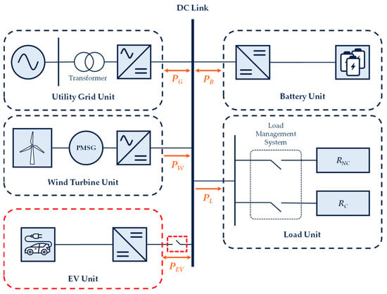
Figure 1.
Configuration of a decentralized DCMG.
The utility grid unit connects the main grid to the DC-link through a transformer and a bidirectional AC/DC converter. The wind turbine unit uses a permanent magnet synchronous generator (PMSG) to convert mechanical power into electrical power, which is then fed into the DC-link through a unidirectional AC/DC converter. Both the battery unit and the EV unit utilize bidirectional interleaved DC/DC converters to exchange powers with the DC-link. The load unit which consists of critical load (RC) and non-critical load (RNC) employs electronic switches for load shedding and load reconnection.
In the DCMG system, several power units such as the utility grid, battery, and EV have bidirectional power flow, enabling them to either supply power into the DC-link, or absorb power from the DC-link. In contrast, the wind turbine unit only supplies power into the DC-link, and the load unit absorbs power from the DC-link. As shown in Figure 1, PG, PB, PW, and PL denote the power flow of the utility grid unit, the battery unit, the wind turbine unit, and the load unit, respectively. The power injection and current flow into the DC-link are represented as negative (−) values, while power absorption and current flow from the DC-link are represented as positive (+) values. The power of the EV unit (PEV) functions similarly to the battery unit, serving as an additional ESS. The operational details and control methods of converters are determined by the proposed PFCS of the DCMG, which will be discussed in subsequent sections. The EV unit is dealt with separately from the proposed PFCS and functions as an additional plug-and-play ESS.
2.2. Management of Battery SOC
The management strategy of the battery SOC level used in the proposed decentralized PFCS of the DCMG system is shown in Figure 2. Battery operation is determined according to SOC levels and connected loads as specified in Table 1.

Figure 2.
Battery operating states according to SOC level.

Table 1.
SOC levels for battery unit.
First, to prevent the critical situation, SOCB,Min is defined as 5%, which is the level to stop discharging in the islanded mode. At a battery SOC level lower than SOCB,Min, the battery unit is always in charging mode. The second SOC level is SOCB,Emg-L, at which the load reconnection process is activated for the critical load RC. The third SOC level defined as SOCB,Emg-H is used for two purposes. This level is used to stop discharging the battery in grid-connected mode with high electricity price condition. It is also used to activate load shedding for the non-critical load RNC in the islanded mode. The fourth SOC level is defined as SOCB,LR which is used to activate load reconnection for non-critical load RNC if the battery unit has activated load shedding previously for RNC. The last SOC level defined as SOCB,Max is used to stop charging in both islanded and grid-connected modes.
3. Proposed Control Strategy of Decentralized DCMG
3.1. Operation Modes of Utility Grid Unit
Figure 3 shows the operation modes of the utility grid unit which are composed of one steady-state mode and two transition modes. The first mode, denoted by RdG1, in Figure 3 represents the steady-state mode in which the DC-link voltage Vdc is always maintained at the nominal DC-link voltage VNom. In RdG1 operation, the utility grid unit works in the region between and to supply power to the DC-link by rectifier (REC) mode, or to absorb power from the DC-link by inverter (INV) mode.
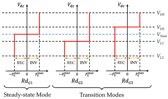
Figure 3.
Operation modes of utility grid unit.
The second mode RdG2, is used during the transition period when the electricity price condition changes from normal to high. When this condition happens, the utility grid unit regulates Vdc to VL1 by adopting the RdG2 mode in order that the battery unit identifies the electricity price condition change from normal to high by detecting the DC-link voltage variation. Then, the battery unit changes the operation in order to work properly under the high electricity price condition. After some predetermined time, the operation of the utility grid unit switches back to RdG1 to maintain Vdc to VNom.
Another transition mode RdG3 is used when the electricity price condition changes from high to normal, or when the grid is reconnected after a fault. Under these conditions, the utility grid unit temporarily changes from Vdc to VH1 by the RdG3 mode for the purpose of transmitting this information to other power units. After some predetermined time, the operation of the utility grid unit is returned to steady-state mode RdG1.
3.2. Operation Modes of Battery Unit
The operation modes of the battery unit consist of five steady-state modes and four transition modes as illustrated in Figure 4 and Figure 5. Figure 4 shows the steady-state operation modes of the battery unit which are separated into the operations in the grid-connected mode and islanded mode.
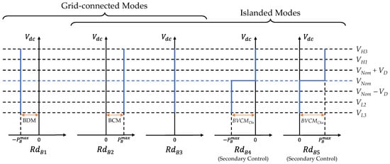
Figure 4.
Steady-state operation modes of battery unit.

Figure 5.
Secondary and primary controls to implement RdB4 and RdB5. (a) Block diagram of the secondary control and primary control; (b) V-P droop curves (VNL – Pref).
In steady-state grid-connected mode operation, the battery unit can work in the battery maximum current discharging mode (BDM) with RdB1, the battery maximum current charging mode (BCM) with RdB2, or idle mode with RdB3. In steady-state islanded mode operation, the battery unit can operate in BCM with RdB2, idle mode with RdB3, battery secondary voltage control discharging mode (BVCMDis) with RdB4, or battery secondary voltage control charging mode (BVCMCha) with RdB5. The RdB1 mode is utilized in the grid-connected mode when the utility grid has high electricity price conditions. The RdB2 mode is deployed either in the grid-connected mode with normal electricity price conditions, or in the islanded mode with the wind turbine unit regulating the DC-link voltage to VNom. The RdB3 mode indicates the idle mode which is used when the battery SOC level reaches SOCB,Max in the charging condition, or when the battery SOC level falls to SOCB,Emg-H in the high electricity price condition. The RdB4 and RdB5 modes, which are only used in the islanded mode, implement BVCMDis and BVCMCha. To regulate the DC-link voltage at VNom, the operation of BVCMDis and BVCMCha is achieved by the primary droop control and secondary voltage control as shown in Figure 5. The RdB4 mode is utilized when the generated power of the wind turbine unit is less than the demanded load in the islanded mode. In contrast, the RdB5 mode is deployed to guarantee the DC-link voltage to VNom when the power of the wind turbine unit is in the region [PL, ].
Figure 5 shows the secondary and primary controls to implement RdB4 and RdB5. The block diagram for the primary control and secondary control is shown in Figure 5a in which the primary control generates reference power (Pref) to achieve power balance, and the secondary control regulates the DC-link voltage to VNom. In secondary control, the DC-link voltage is compared to the VNom and the error is fed to the proportional-integral (PI) controller. The PI controller output is added with the initial no-load voltage () to produce a no-load voltage (VNL) in the primary control. Finally, the VNL is compared to the nominal voltage (VNom) to generate reference power (Pref) by using the droop constant (Rd). Figure 5b shows the V-P droop curves for Pref and VNL.
Figure 6 shows the transition operation modes of the battery unit used only in the islanded mode. The first mode RdB6 denotes the battery voltage control emergency mode (BVCMEmg1) which is used to decrease the DC-link voltage to VL2 when the battery SOC level drops to SOCB,Emg-H in discharging. The RdB6 mode is used to allow another ESS to respond to low DC-link voltage and to regulate DC-link voltage back to VNom. The second transition mode RdB7 implements the battery voltage control emergency discharging mode (BVCMEmg2,Dis) and battery voltage control emergency charging mode (BVCMEmg2,Cha). These modes are used to maintain the DC-link voltage at VL2 after RdB6 activation for RNC load shedding in the islanded mode.
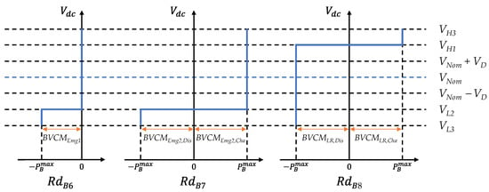
Figure 6.
Transition operation modes of battery unit in islanded mode.
The last transition mode RdB8 implements the battery voltage control load reconnection discharging mode (BVCMLR,Dis) and battery voltage control load reconnection charging mode (BVCMLR,Cha). These modes are deployed to increase the DC-link voltage at VH1 for load reconnection in the islanded mode. In the RdB8 mode, the critical load RC is reconnected as the battery SOC level reaches SOCB,Emg-L. When the battery SOC level further increases to SOCB,LR, the non-critical load RNC is also reconnected.
3.3. Operation Modes of Wind Turbine Unit
Figure 7 shows the operation of the wind turbine unit which has two operation modes in steady-state and one operation mode in transient condition. The first mode, RdW1, denotes the wind voltage droop control mode (WVDCM) in the islanded mode during transition condition. In this mode, a primary droop control is utilized to reduce the wind power generation. The second mode, RdW2 is a steady-state operation and happens when the wind turbine unit regulates the DC-link voltage in the islanded mode using wind voltage control mode (WVCM). When the absolute of the wind turbine power(|PW|) is higher than the sum of PL and , the WVCM mode uses a PI controller for DC-link voltage regulation. The third mode, RdW3, is the maximum power point tracking (MPPT) mode that is utilized to supply the maximum power to the DC-link either in the grid-connected mode or islanded mode.
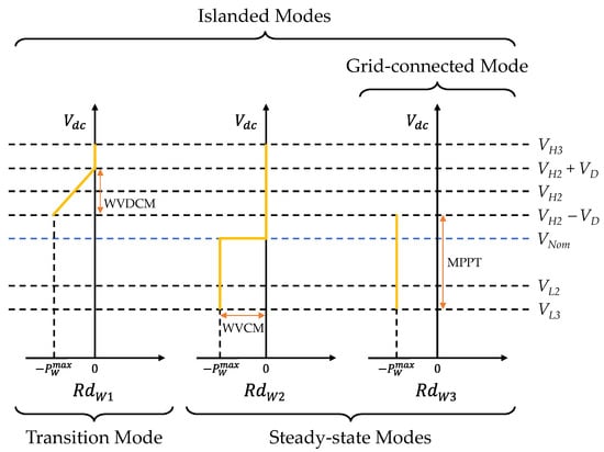
Figure 7.
Operation modes of wind turbine unit.
3.4. Load Unit
The load unit consists of two categories of load, which are critical load (RC) and non-critical load (RNC). The total load (RT) represents the case that both RC and RNC are connected. The load unit also detects the DC-link voltage for load shedding and load reconnection purposes. The details of the DC-link voltage detection are discussed in the next subsection.
3.5. Voltage Detection
In the proposed decentralized PFCS for a DCMG system, the power balance and voltage regulation are effectively achieved by detecting the DC-link voltage values without DCLs. All the power units can properly change the operation modes according to the DC-link voltage values after some predetermined time.
Figure 8 shows the transition operation of DC-link voltage and information transmission in the case of Vdc = VH1. Figure 8a shows the process of RC reconnection in the islanded mode. As soon as the battery SOC level reaches SOCB,Emg-L, the battery unit starts to operate with RdB8 mode within 5 s to increase Vdc to VH1. The load unit continuously monitors the Vdc level. Finally, if the Vdc value reaches VH1, the load unit reconnects RC after =3 s.
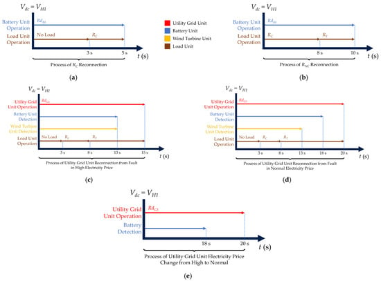
Figure 8.
Transition operation of DC-link voltage and information transmission in case of Vdc = VH1. (a) Process of RC reconnection; (b) Process of RNC reconnection; (c) Process of utility grid unit reconnection from fault in high electricity price condition; (d) Process of utility grid unit reconnection from fault in normal electricity price condition; (e) Process of utility grid unit electricity price change from high to normal.
Figure 8b shows the process of RNC reconnection in the islanded mode. As the battery SOC level reaches SOCB,LR, the battery unit starts the RdB8 mode within 10 s to increase the DC-link voltage to VH1. The load unit continuously monitors whether the DC-link voltage Vdc is increased to VH1. If the Vdc reaches to VH1, the load unit reconnects RNC after =8 s, resulting in the total load of RT as shown in Figure 8b.
Figure 8c shows the process of the utility grid unit reconnection from fault in high electricity price condition. In this condition, the utility grid unit operates with RdG3 to increase the DC-link voltage to VH1. After 3 s, RC is reconnected if RC has been disconnected previously by load shedding. After 8 s, RNC is reconnected if RNC has been disconnected previously by load shedding. After 13 s, by observing the DC-link voltage value, the battery and the wind turbine units recognize that the utility grid is reconnected from the fault. Then, the wind turbine unit is returned to the MPPT mode to supply the maximum power to the DC-link. Depending on the SOC level, the battery unit works in BDM, BCM, or idle mode. After the transmission of the utility grid recovery information to other power units has been accomplished during 15 s, the utility grid unit returns to steady-state RdG1 mode to regulate the DC-link voltage at VNom.
Figure 8d shows the process of the utility grid unit reconnection from fault in normal electricity price condition. Similar to Figure 8c, the utility grid unit operates with RdG3 to increase the DC-link voltage to VH1. If the load shedding has been activated previously, similar load reconnection is achieved after 3 s and 8 s, respectively. After 13 s, the wind turbine unit identifies the utility grid recovery, and starts the MPPT mode. It is worth mentioning that the wind turbine unit identifies only the utility grid recovery without having the exact information of the utility grid price condition. Only the battery unit recognizes the utility grid recovery as well as the normal electricity price condition after 18 s, if the RdG3 operation by the utility grid unit lasts until 20 s. Then, the battery unit operates either in BCM or idle mode depending on the SOC level. Similarly, after the utility grid recovery information has been sent to other power units within 20 s, the utility grid unit changes the transition operation RdG3 to steady-state operation RdG1 to regulate the DC-link voltage at VNom.
Figure 8e shows the process of the utility grid unit electricity price change from high to normal. The utility grid unit operates with RdG3 to increase the DC-link voltage to VH1. After 18 s, the battery unit detects this voltage level to identify the electricity price change. Then, the battery unit changes the operation either in BCM or idle mode. Finally, after 20 s, the utility grid unit changes the operation to RdG1 to regulate the DC-link voltage at VNom in the steady-state condition.
Figure 9 shows the transition operation of DC-link voltage and information transmission in case of different values of Vdc. Figure 9a shows the process of the utility grid unit electricity price change from normal to high by using Vdc = VL1. In this condition, the utility grid unit first operates in RdG2 and decreases the DC-link voltage to VL1. After 3 s, the battery unit acknowledges the electricity price condition change from normal to high by monitoring the Vdc level, and changes operation mode to BDM, idle, or BCM depending on the battery SOC level. After 5 s, the utility grid unit stops operating the RdG2 and returns to steady-state operation mode RdG1.
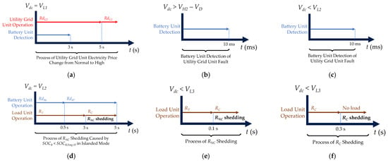
Figure 9.
Transition operation of DC-link voltage and information transmission in case of different values of Vdc. (a) Vdc = VL1 for process of utility grid unit electricity price change from normal to high; (b) Vdc > VH2 − VD for process of utility grid fault; (c) Vdc < VL2 for process of utility grid fault; (d) Vdc = VL2 for process of RNC shedding caused by SOCB < SOCB,Emg-H in islanded mode; (e) Vdc < VL3 for process of RNC shedding; (f) Vdc < VL3 for process of RC shedding.
Figure 9b,c show how the battery unit detects the utility grid unit fault with two different high-voltage and low-voltage conditions, respectively. If a fault occurs in the utility grid unit during INV mode operation, the DC-link voltage is rapidly increased. Figure 9b shows the detection process of the battery unit for this case. On the contrary, Figure 9c shows the detection process of the battery unit for grid fault with low voltage when the utility grid unit works in REC mode before the fault. If those DC-link voltage conditions last for 10 ms, the battery unit confirms the grid fault.
Figure 9d shows the process of RNC load shedding in the islanded mode. As the battery unit SOC level reaches SOCB,Emg-H in the islanded mode, the battery unit changes operation to RdB6 for BVCMEmg1, and reduces the DC-link voltage to the second level of low DC-link voltage (VL2). As soon as the DC-link voltage decreases to VL2, the battery unit changes the operation to RdB7 after 0.5 s, and the load unit activates load shedding for RNC after 3 s.
Figure 9e,f show the process of load shedding for RNC and RC, respectively. Figure 9e shows the process of RNC shedding after 0.1 s when the DC-link voltage drops to the third level of low DC-link voltage (VL3). Figure 9f shows the process of RC shedding after 0.3 s when the DC-link voltage falls to VL3.
Figure 10 shows the transition operation of DC-link voltage and information transmission in the islanded mode the in case of Vdc > VH2 − VD. Figure 10a shows the process of the battery unit operation change from BVCMDis to BVCMCha in case of |PW| > PL in the islanded mode. When |PW| is higher than PL, the wind turbine unit operates in WVDCM and Vdc increases to the value of VH2 − VD. By detecting this increased voltage, the battery unit operation is changed from RdB4 to RdB5 after 1 s. Then, the wind turbine unit operates back in the MPPT mode as the battery unit regulates DC-link voltage in BVCMCha.

Figure 10.
Transition operation of DC-link voltage and information transmission in case of Vdc > VH2 − VD because of the wind turbine unit WVDCM operation in islanded mode. (a) Vdc > VH2 − VD for process of battery unit operation change from BVCMDis to BVCMCha caused by |PW| > PL in islanded mode; (b) Vdc > VH2 − VD for process of the wind turbine unit regulating the DC-link voltage to VNom.
Figure 10b shows the process of the wind turbine unit regulating the DC-link voltage to VNom. When |PW| is higher than PL even with battery charging operation, the wind turbine unit operates in WVDCM in RdW1 and Vdc increases to the value of VH2 − VD. Then, after 3 s, the battery unit changes the operation from BVCMCha in RdB5 to BCM in RdB2. After 5 s, the wind turbine unit changes operation from WVDCM in RdW1 to WVCM in RdW2.
4. Power Flow Control Strategy of Decentralized DCMG
In this section, the proposed PFCS is explained to realize an effective decentralized DCMG control and cooperation method with the EV unit. The PFCS determines the operating modes of all power units within the DCMG, by taking into account the factors such as wind power generation, load demand, battery SOC level, and availability of the utility grid unit. In addition, the grid-connected operation of the DCMG system also considers the electricity price condition to determine the suitable operation of the power units. The proposed PFCS is categorized into three main operation modes: grid-connected mode operation, islanded mode operation, and transition mode operation.
4.1. PFCS of Decentralized DCMG in Grid-Connected Mode
Table 2 shows the DCMG states and operation modes in the steady-state grid-connected mode. In this study, the DCMG states in the grid-connected mode are divided according to the electricity price conditions and battery SOC level as defined in Figure 2. As shown in Table 2, grid-connected operation modes at steady-state are determined according to the DCMG states. For example, DCMG state 1 represents the condition that the utility grid unit has the normal electricity price condition and the battery unit SOC level is in the FB region. In DCMG state 1, the DCMG works with the operation mode OP1.

Table 2.
Steady-state DCMG states and operation modes in grid-connected mode (1 = True, 0 = False).
Table 3 shows the steady-state operation modes for individual power units in the grid-connected mode of the decentralized DCMG system.

Table 3.
Steady-state operation modes for individual power units of decentralized DCMG in grid-connected mode according to operation modes in Table 2.
Operation mode OP1: In this mode, the utility grid unit operates with RdG1 mode, the battery unit is in idle mode with RdB3, the wind turbine unit operates in the MPPT mode with RdW3, and all loads are connected. This operation mode is used in DCMG states 1 and 7. In either case, the battery enters idle mode to prevent further charging or discharging.
Operation mode OP2: In this mode, the utility grid unit operates with RdG1 mode, the battery unit is in BCM mode with RdB2, the wind turbine unit operates in the MPPT mode with RdW3, and all loads are connected. This operation mode is used in DCMG state 2 through 4. In this case, the battery works in BCM mode to charge the battery to SOCB,Max.
Operation mode OP3: In this mode, the utility grid unit operates with RdG1 mode, the battery unit is in BDM mode with RdB1, the wind turbine unit operates in the MPPT mode with RdW3, and all loads are connected. This operation mode is used in DCMG states 5 and 6. In this case, the battery works in BDM mode to supply power to DC-link.
4.2. PFCS of Decentralized DCMG in Islanded Mode
The proposed PFCS for the decentralized DCMG in the islanded mode are divided according to the load operation, the battery SOC level, and the wind turbine unit power condition. Table 4, Table 5 and Table 6 show the DCMG states and operation modes in the steady-state islanded mode, mainly according to the wind turbine power conditions. Table 4 denotes DCMG states and operations in the islanded mode for condition |PW| < PL. For example, the DCMG state 8 represents the condition that the load unit operates with total load RT and the battery SOC level is in EB or FB region with |PW| < PL. In DCMG state 8, the DCMG works with the operation mode OP4.

Table 4.
Steady-state DCMG states and operation modes in islanded mode with condition |PW| < PL (1 = True, 0 = False).

Table 5.
Steady-state DCMG states and operation modes in islanded mode with condition PL + PB > |PW|> PL (1 = True, 0 = False).

Table 6.
Steady-state DCMG states and operation modes in islanded mode with condition |PW|> PL + PB (1 = True, 0 = False).
Table 5 denotes DCMG states and operations in the islanded mode for condition PL + PB > |PW| > PL. In this Table, the DCMG state 13 represents the condition that the load unit operates with total load RT and the battery SOC level is in the EB region with PL + PB > |PW| > PL. In DCMG state 13, the DCMG works with the operation mode OP6.
Table 6 denotes DCMG states and operations in the islanded mode for condition |PW| > PL + PB. In this Table, DCMG state 20 represents the condition that the load unit operates with total load RT and the battery SOC level is in the FB region. In DCMG state 20, the DCMG works with the operation mode OP9.
Table 7 shows the steady-state operation modes for individual power units in the islanded mode of the decentralized DCMG system.

Operation mode OP4: In this mode, the battery unit is in BVCMDis with RdB4, the wind turbine unit operates in the MPPT mode with RdW3, and all loads are connected. This operation mode is used in DCMG states 8 and 9. In either case, the battery SOC level is higher than SOCB,Emg-H. The battery unit regulates DC-link voltage to VNom and the wind turbine unit operates in MPPT mode as |PW| < PL.
Operation mode OP5: This mode is similar to operation mode OP4 except for the load unit that only operates with RC. This mode is used in DCMG states 10 through 12. In this case, the battery unit regulates DC-link voltage to VNom and the wind turbine unit operates in MPPT mode. This operation mode is used after the RNC load shedding because the battery SOC level is lower than SOCB,Emg-H or it does not fulfill RNC reconnection condition.
Operation mode OP6: In this mode, the battery unit is in BVCMCha with RdB5, the wind turbine unit operates in the MPPT mode with RdW3, and all loads are connected. This mode is used in DCMG states 13 and 14. In either case, the battery SOC level is higher than SOCB,Emg-H but lower than SOCB,Max.
Operation mode OP7: This mode is similar to OP6 except for the load unit that only operates with RC. This mode is used in DCMG states 15 through 17. In this case, the battery unit regulates DC-link voltage to VNom and the wind turbine unit operates in MPPT mode with condition PL + PB > |PW| > PL. This mode is used after the RNC load shedding because the battery SOC level is lower than SOCB,Emg-H or it does not fulfill the RNC reconnection condition.
Operation mode OP8: This mode is similar to OP6 except that the load is not connected. This mode is used in DCMG states 18 and 19. In this case, the battery unit regulates DC-link voltage to VNom and the wind turbine unit operates in MPPT mode as PL + PB > |PW| > PL with PL = 0. This mode is used after the RNC and RC load shedding caused by insufficient power as the battery SOC level reaches SOCB,Min, or if the battery SOC level still does not reach SOCB,Emg-L for RC reconnection.
Operation mode OP9: In this mode, the battery unit is in idle mode with RdB3, the wind turbine unit operates in the WVCM mode with RdW2, and all loads are connected. This mode is only used in DCMG state 20. In this case, the battery SOC level is higher than SOCB,Max. The wind turbine unit regulates DC-link voltage to VNom in charging mode as |PW| > PL + PB with PB = 0.
Operation mode OP10: In this mode, the battery unit is in BCM with RdB5, the wind turbine unit operates in the WVCM mode with RdW2, and all loads are connected. This mode is used in DCMG states 21 and 22. In either case, the battery SOC level is higher than SOCB,Emg-H and lower than SOCB,Max.
Operation mode OP11: This mode is similar to OP10 except for the load unit that only operates with RC. This mode is used in DCMG states 23 through 25, in which the battery unit is in maximum power charging and the wind turbine unit operates in WVCM mode as |PW| > PL + PB. This mode is used after the RNC load shedding because the battery SOC level is lower than SOCB,Emg-H, or it does not fulfill the RNC reconnection condition.
Operation mode OP12: This mode is similar to OP10 except that the load is not connected. This mode is used in DCMG states 26 and 27, in which the battery unit is in maximum power charging and the wind turbine unit operates in WVCM mode as |PW| > PL + PB with PL = 0. This mode is used after the RNC and RC load shedding caused by insufficient power as the battery SOC level reaches SOCB,Min, and the battery SOC level still does not reach SOCB,Emg-L for RC reconnection.
4.3. Transition Mode Operations of Decentralized DCMG
Table 8 shows transition conditions and operation modes for the proposed PFCS which are used for transmitting information to other power units in this study. Thirteen transition states of T1 through T13 are defined as follows:

Table 8.
Transition conditions and operation modes of decentralized DCMG.
Conditions for mode T1: This transition condition happens when the utility grid unit electricity price is changed from normal to high. When this condition occurs, the utility grid unit reduces the DC-link voltage VL1 as shown in Figure 9a. Then, the battery unit acknowledges this information in the predetermined time.
Conditions for mode T2: This transition condition happens when the utility grid unit electricity price is changed from high to normal. When this condition occurs, the utility grid unit increases the DC-link voltage to VH1 as shown in Figure 8e. Then, the battery unit acknowledges this information by detecting the voltage level.
Conditions for mode T3: This transition condition happens when the utility grid unit electricity price is high and the battery SOC level is lower than SOCB,Emg-L.
Conditions for mode T4: This transition condition happens when the utility grid unit is reconnected after a fault. By observing the DC-link voltage value, the battery unit recognizes that the utility grid is reconnected with normal or high electricity prices as in Figure 8c,d. The wind turbine unit also recognizes the reconnection of the utility grid unit, and returns to the MPPT mode. The load unit reconnection is also initiated.
Conditions for mode T5: This transition condition happens when the battery SOC level reaches SOCB,Emg-H in the islanded mode. The battery unit reduces the DC-link voltage to VL2 in discharging mode using BVCMEmg1 for 0.5 s as shown in Figure 9d. This is to enable another ESS to regulate DC-link voltage to VNom.
Conditions for mode T6: This transition condition happens after T5 when the battery SOC level reaches SOCB,Emg-H in the islanded mode. The battery unit maintains the DC-link voltage at VL2 with RdB7 during 5 s as shown in Figure 9d. The load unit then recognizes the DC-link voltage value and activates RNC shedding.
Conditions for mode T7: This transition condition happens when the battery SOC level reaches SOCB,Min in the islanded mode. The battery unit operation is switched to BVCMCha and the load unit activates RC shedding as shown in Figure 9f.
Conditions for mode T8: This transition condition happens when the battery SOC level reaches SOCB,Emg-L in the islanded mode after previous decrease below SOCB,Min. The battery unit increases the DC-link voltage to VH1 as in Figure 8a. The load unit continuously monitors the DC-link voltage level and reconnects RC.
Conditions for mode T9: This transition condition happens when the battery SOC level reaches SOCB,LR in the islanded mode after previous decrease below SOCB,Emg-H. The battery unit increases the DC-link voltage to VH1 as in Figure 8b. The load unit continuously monitors the DC-link voltage level and reconnects RNC.
Conditions for mode T10: This transition condition happens when the wind turbine unit power is higher than the load requirement, and the battery unit is in BVCMDis. The wind turbine unit increases the DC-link voltage and operates in WVDCM as in Figure 10a. The battery unit changes operation from BVCMDis to BVCMCha after 1 s. The wind turbine unit operates back to the MPPT mode as the battery unit regulates DC-link voltage in BVCMCha.
Conditions for mode T11: This transition condition happens when the wind turbine unit power is higher than the load requirement, and the battery unit charges power. The wind turbine unit increases the DC-link voltage and operates in WVDCM as in Figure 10b. The battery unit changes operation from BVCMCha to BCM after 3 s. The wind turbine unit operates in WVCM and regulates DC-link voltage after 5 s.
Conditions for mode T12: This transition condition happens when the wind turbine unit power is higher than the load requirement, and the battery unit is in idle mode after reaching SOCB,Max. The wind turbine unit increases the DC-link voltage and operates in WVDCM. After 5 s, the wind turbine unit operates in WVCM and regulates DC-link voltage.
Conditions for mode T13: This transition condition happens when the wind turbine unit power is decreased. The wind turbine unit changes operation to the MPPT mode as soon as the DC-link voltage falls below VL2. When the DC-link voltage reduces to VL2, the battery unit also changes operation from BVCMCha, BCM, or idle mode, to BVCMDis, and then regulates the DC-link voltage.
Table 9 shows the transition operation modes for individual power units of the decentralized DCMG system.

Table 9.
Transition operation modes for individual power units of decentralized DCMG according to operating conditions in Table 8.
Operation mode T1: In this mode, the utility grid unit operates with RdG2 mode to reduce the DC-link voltage to VL1 as in Figure 9a, the battery unit operates either in BCM with RdB2 or idle mode with RdB3, and the wind turbine unit operates in the MPPT mode with RdW3, and all loads are connected. The battery unit then changes operation to BDM with RdB1, BCM with RdB2, or idle mode with RdB3 depending on the battery SOC level. If the battery unit operates in BDM, then the next mode is OP3. If the battery unit changes operation to idle mode, then the next mode is OP1. If the battery SOC level is in AB or BB region, then the battery unit operates in BCM to charge until SOCB,Emg-H and the next mode is T3.
Operation mode T2: In this mode, the utility grid unit operates with RdG3 mode to increase the DC-link voltage to VH1 as in Figure 8e, the battery unit operates in BDM with RdB1, BCM with RdB2, or idle mode with RdB3, the wind turbine unit operates in the MPPT mode with RdW3, and all loads are connected. The battery unit then changes operation to either BCM with RdB2, or idle mode with RdB3 depending on the battery SOC level. If the battery unit operates in BCM, then the next mode is OP2. If the battery unit changes operation to idle mode, then the next mode is OP1.
Operation mode T3: In this mode, the utility grid unit operates with RdG1 and regulates the DC-link voltage to VNom, the battery unit operates in BCM with RdB2, the wind turbine unit operates in the MPPT mode with RdW3, and all loads are connected. This mode follows T1 when the battery SOC level is lower than SOCB,Emg-L.
Operation mode T4: In this mode, the utility grid unit operates with RdG3 to increase the DC-link voltage to VH1, the battery unit is in BCM with RdB2, idle mode with RdB3, BVCMDis with RdB4, or BVCMCha with RdB5, the wind turbine unit operates either in the MPPT mode with RdW3, or WVCM mode with RdW2, and the load unit operates with RT, RC, or no load connection. As shown in Figure 8c,d, if the load shedding has been previously activated, the load reconnection process is initiated. The wind turbine unit recognizes the DC-link voltage and returns to the MPPT mode from WVCM. The battery unit recognizes electricity price, and changes operation to BDM with RdB1, BCM with RdB2, or idle mode with RdB3 depending on the battery SOC level. If the battery unit operates in BDM, then the next mode is OP3. If the battery unit changes operation to idle mode, then the next mode is OP1. If the battery unit operates in BCM with the normal electricity price condition, then the next mode is OP2. If the battery unit operates in BCM with high electricity price, then the next mode is T3.
Operation mode T5: In this mode, the battery unit operates in the BVCMEmg1 with RdB6 and regulates DC-link voltage to VL2, the wind turbine unit operates in the MPPT mode with RdW3, and all loads are connected. The next mode is T6 to maintain the DC-link voltage with the battery unit operating in RdB7 as in Figure 9d.
Operation mode T6: In this mode, the battery unit operates with RdB7 to maintain the DC-link voltage to VL2, the wind turbine unit operates in the MPPT mode with RdW3, and all loads are connected. The load unit continuously monitors the DC-link voltage level and starts RNC shedding as in Figure 9d. The next mode is OP11 if the previous steady-state operation of the battery unit is in BCM with RdB2. If the previous steady-state operation of the battery unit is in BVCMCha with RdB5, then the next mode is OP7 to change from BVCMEmg2,Cha to BVCMCha, or OP5 to change from BVCMEmg2,Dis to BVCMDis.
Operation mode T7: In this mode, the battery unit is in BVCMCha with RdB5 as the battery SOC level falls below SOCB,Min, the wind turbine unit operates in the MPPT mode with RdW3, and only the critical load is connected. When the wind power is not sufficient for the load, the voltage is reduced, and RC shedding is triggered as in Figure 9f.
Operation mode T8: In this mode, the battery unit regulates the DC-link voltage to VH1 either in BVCMLR,Cha, or BVCMLR,Dis with RdB8 as the battery SOC level reaches SOCB,Emg-L, the wind turbine unit operates either in the MPPT mode with RdW3 or in the WVCM with RdW2, and the load is not connected. The load unit monitors the DC-link voltage to reconnect RC as in Figure 8a. The next mode is OP11 if the previous steady-state operation of the battery unit is in BCM with RdB2. If the previous steady-state operation of the battery unit is in BVCMCha with RdB5, the next mode is OP7 to change from BVCMLR,Cha to BVCMCha, or OP5 to change from BVCMLR,Dis to BVCMDis.
Operation mode T9: In this mode, the battery unit regulates the DC-link voltage to VH1 either in BVCMLR,Cha, or in BVCMLR,Dis with RdB8 as the battery SOC level reaches SOCB,LR, the wind turbine unit operates either in the MPPT mode with RdW3 or in the WVCM with RdW2, and only the RC load is connected. The load unit monitors the DC-link voltage to reconnect RNC as in Figure 8b. The next mode is OP10 if the previous operation of the battery unit is in BCM with RdB2. If the previous operation of the battery unit is in BVCMCha with RdB5, the next mode is OP6 to change from BVCMLR,Cha to BVCMCha, or OP4 to change from BVCMLR,Dis to BVCMDis.
Operation mode T10: In this mode, the battery unit is in BVCMDis with RdB4, the wind turbine unit operates in WVDCM with RdW1, and the load unit operates with RT, RC, or no load connection. The DC-link voltage is increased by the wind turbine unit. The battery unit operation is changed from BVCMDis with RdB4 to BVCMCha with RdB5 and the wind turbine unit operates back in the MPPT mode as in Figure 10a. If the total load is connected, the next mode is OP6. If only the RC load is connected, the next mode is OP7. Finally, if there is no load connection before T10, the next mode is OP8.
Operation mode T11: In this mode, the battery unit is in BVCMCha with RdB5, the wind turbine unit operates in the WVDCM with RdW1, and the load unit operates with RT, RC, or no load connection. The DC-link voltage is increased by the wind turbine unit, the battery unit operation is changed from BVCMCha with RdB5 to BCM with RdB2, and the wind turbine unit regulates the DC-link voltage to VNom in WVCM with RdW2 as in Figure 10b. If the total load is connected, the next mode is OP10. If only RC load is connected, the next mode is OP11. Lastly, if there is no load connection, the next mode is OP12.
Operation mode T12: In this mode, the battery unit is in idle mode with RdB3, the wind turbine unit operates in WVDCM with RdW1, and all the loads are connected. The DC-link voltage is increased by the wind turbine unit, and the wind turbine unit regulates the DC-link voltage to VNom in WVCM with RdW2 as in Figure 10b with the battery unit still working in idle. The next mode is OP9.
Operation mode T13: In this mode, the battery unit is in BCM with RdB2, BVCMCha with RdB5, or idle mode with RdB3, the wind turbine unit operates in WVCM with RdW2, and the load unit operates with RT, RC, or no load connection. The DC-link voltage is decreased as the wind turbine unit power is insufficient to regulate the DC-link voltage to VNom. As soon as the DC-link voltage falls below VL2, the wind turbine unit operates in the MPPT mode with RdW3 and the battery unit regulates the DC-link voltage to VNom with BVCMDis with RdB4. If all the loads are connected, the next mode is OP4. If only the RC load is connected, the next mode is OP5. If the load is not connected, the next mode is T10, in which the DC-link voltage is increased, and the battery unit changes operation to BVCMCha with RdB5.
4.4. Co-Operation with EV Unit
The integration of an EV unit as additional ESS is also studied to improve the scalability of the proposed decentralized DCMG system. Figure 11 shows the operation modes for the EV unit. The operation modes of the EV unit only work at steady-state and consist of three grid-connected modes and four islanded modes. For the EV unit, operation modes are simplified without considering load shedding or load reconnection as in the battery unit because the EV can be disconnected from the DCMG at any time.
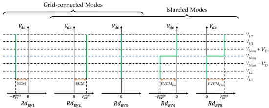
Figure 11.
Operation modes of EV unit.
The first mode, RdEV1, is the EV maximum current discharging mode (EDM) that is used when the utility grid is in the high electricity price condition. The second mode, RdEV2, is the EV maximum current charging mode (ECM) that is used under the normal electricity price condition and the condition that the wind power unit regulates the DC-link voltage. The third mode, RdEV3, is the idle mode to stop charging when the EV SOC reaches SOCEV,Max, or to stop discharging when the EV SOC reaches SOCEV,Min, respectively. The fourth mode, RdEV4, is the EV voltage control mode by discharging (EVCMDis) that is used in the islanded mode when the battery unit cannot regulate the DC-link voltage because of the low battery SOC level. The fifth mode, RdEV5, is the EV voltage control by charging (EVCMCha) that is used to absorb excessive power from the DC-link. The EVCMDis and EVCMCha use the PI control to maintain the DC-link voltage at VNom.
Table 10 shows the EV SOC levels used in this study. Because the EV unit may connect and disconnect at any time, the transition modes for load shedding and load reconnection are not considered for the EV unit. The minimum and maximum SOC levels for the EV unit are used solely to prevent overdischarge and overcharge.

Table 10.
SOC levels for EV unit.
The EV unit also has the transition times to be able to cooperate with the battery unit. Figure 12 shows the transition operation of DC-link voltage and information transmission to cooperate with the EV unit. Figure 12a shows the battery and EV unit detection times for the utility grid unit fault when the previous utility grid unit operation is in the REC mode. Even while the EV unit acknowledges the utility grid fault at the same instant as the battery unit, it operates in idle mode with RdEV3. The EV unit continuously monitors the DC-link voltage and regulates the DC-link voltage after 100 ms when the DC-link voltage is higher than VH2 − VD. Figure 12b shows the process of utility grid fault identification by the EV unit when the previous utility grid unit operation is in INV mode. The entire process is similar to Figure 12a except that the EV unit takes the regulation of the DC-link voltage with RdEV4 with the condition Vdc < VL2. Figure 12c shows the EV detection process of insufficient power in the DCMG system. After 100 ms when the DC-link voltage is lower than or equal to VL2, the EV unit regulates the DC-link voltage at VNom with RdEV4.

Figure 12.
Transition operation of DC-link voltage and information transmission for the EV unit cooperation. (a) Vdc > VH2 − VD for process of utility grid fault; (b) Vdc < VL2 for process of utility grid fault; (c) Vdc ≤ VL2 for process of insufficient power detection.
Figure 13 shows the transition operation of DC-link voltage and information transmission for the EV unit cooperation in the islanded mode in the case of Vdc > VH2 − VD. Figure 13a shows the process of the EV unit operation change from idle to EVCMDis and the battery unit operation change from BVCMCha to BCM caused by |PW| > PL + PB in the islanded mode. This process occurs after the battery unit changes operations from BVCMDis to BVCMCha in Figure 10a. When |PW| is higher than PL and PB, the wind turbine unit operates in WVDCM and Vdc increases to the value of VH2 − VD. By detecting this increased voltage, the EV unit operation is changed from RdEV4 to RdEV5 after 3 s. At the same time, the battery unit operation is changed from RdB5 to RdB2. Then, the wind turbine unit operates back in the MPPT mode as the EV unit regulates DC-link voltage in EVCMCha.

Figure 13.
Transition operation of DC-link voltage and information transmission for EV unit cooperation in case of Vdc > VH2 − VD because of the wind turbine unit WVDCM operation in islanded mode. (a) Vdc > VH2 − VD for process of EV unit operation change from idle to BVCMDis and battery unit operation change from BVCMCha to BCM caused by |PW| > PL + PB in islanded mode; (b) Vdc > VH2 − VD for process of the wind turbine unit regulating the DC-link voltage to VNom.
Figure 13b shows the process of the wind turbine unit regulating the DC-link voltage to VNom. When |PW| is higher than PL even with the battery unit and the EV unit in charging operation, the wind turbine unit operates in WVDCM in RdW1 and Vdc increases to the value of VH2 − VD. Then, after 5 s, the EV unit changes the operation from EVCMCha in RdEV5 to ECM in RdEV2. After 5 s, the wind turbine unit changes operation from WVDCM in RdW1 to WVCM in RdW2.
5. Simulation Results
In this section, the simulations for a decentralized DCMG are conducted by using the PSIM software to assess the feasibility and reliability of the proposed control scheme. To validate the effectiveness under various uncertain DCMG operations, the simulation tests consider several scenarios such as electricity price changes, transition from the grid-connected mode to islanded mode, emergency SOC in the islanded mode, load reconnection in the islanded mode, voltage regulation by the wind turbine in the islanded mode, and the involvement of EV units. Detailed system parameters can be found in Table 11. Throughout the simulation results, PG, PW, PB, and PL stand for the power of the utility grid unit, wind turbine unit, battery unit, and load unit, respectively. It is worth mentioning that the power flow direction follows the definition in Section 2.

Table 11.
System parameters of a decentralized DCMG system.
5.1. Case of Electricity Price Changes
Figure 14 shows the simulation result for the grid-connected case with the transition of the electricity price from normal to high as well as the wind power increase at t = 5 s and decrease at t = 7 s. Initially, the DCMG system starts at t = 1 s with OP2 in the grid-connected mode. The DC-link voltage Vdc is regulated to VNom by the utility grid unit. The battery unit is in BCM mode, and the wind turbine unit is in the MPPT mode. When the electricity price is changed to high at t = 3 s, the utility grid unit regulates Vdc to VL1 for 5 s until t = 8 s in mode T1. In 3 s after Vdc is reduced, the battery unit recognizes the high electricity price condition and changes operation to BDM. As explained in Figure 9a, the transition process is completed at t = 8 s and the DCMG system operates in OP3 at steady-state with Vdc returning to VNom. In mode OP3, the battery is in maximum power discharging to minimize the electricity cost by maximizing the power injection into the utility grid if SOCB is higher than SOCB,Emg-H.
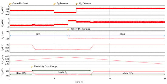
Figure 14.
Simulation result in case of electricity price change from normal to high.
5.2. Case of Grid-Connected Mode to Islanded Mode
Figure 15 shows the simulation result for the transition from the grid-connected mode to islanded mode. Initially, the DCMG system is in mode OP1 at t = 3 s. In this mode, the wind turbine unit operates in the MPPT mode, the battery unit is in idle mode with RdB3 as the battery SOC level is higher than SOCB,Max, the utility grid unit regulates Vdc to VNom with RdG1, and all the loads are connected. As the utility grid unit fault occurs at t = 4 s, Vdc decreases. The battery unit monitors Vdc and changes operation to BVCMDis with RdB4 when Vdc drops below VL2 after 10 ms as shown in Figure 9c. As a result, the operation mode is changed to OP4, in which the battery unit regulates Vdc to VNom in the islanded mode, the wind turbine unit operates in the MPPT mode, and all the loads are connected.
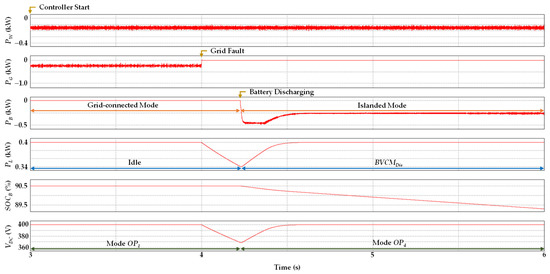
Figure 15.
Simulation result for the transition from grid-connected mode to islanded mode.
5.3. Case of Emergency SOC in Islanded Mode
To verify the reliability of the proposed battery SOC management feature, the simulation result in case of emergency SOC level in the islanded mode is presented in Figure 16. The DCMG system initially operates in OP4 at t = 1 s. The wind turbine unit operates in the MPPT mode, the battery unit regulates Vdc to VNom in BVCMDis with RdB4 in the islanded mode, and all the loads are connected. The battery SOC level slowly decreases because of discharging operation. As soon as the battery SOC level reaches SOCB,Emg-H in the islanded mode, the DCMG operation is changed to mode T5, in which the battery unit works as BVCMEmg1 to reduce Vdc to VL2 during 0.5 s. After that, the DCMG operation is changed again to T6, in which the battery unit maintains Vdc at VL2 with BVCMEmg2,Dis. The load unit continues to monitor Vdc, and triggers RNC shedding after 3 s when Vdc is reduced as shown in Figure 9d. Then, after 5 s when Vdc is reduced, the DCMG works as steady-state mode OP5, in which the battery unit regulates Vdc at VNom using BVCMDis with RdB4, the wind turbine unit operates in the MPPT mode, and the load unit only operates with RC.
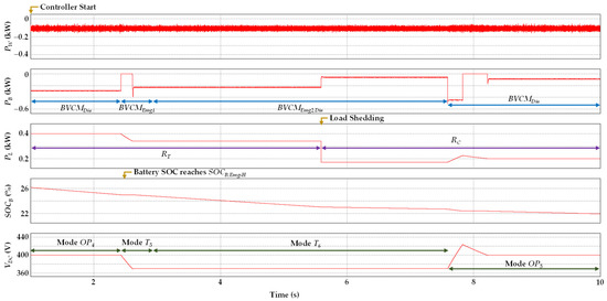
Figure 16.
Simulation result in case of emergency SOC in islanded mode.
5.4. Case of Load Reconnection in Islanded Mode
Figure 17 presents the simulation result for the proposed PFCS in case of load reconnection in the islanded mode. First, the DCMG system operates with OP7 at t = 1 s. In this mode, the wind turbine unit operates in the MPPT mode, the battery unit regulates Vdc with BVCMCha with RdB5, and the load unit only operates with RC. The battery SOC level increases when operated with BVCMCha. As soon as the battery SOC level reaches SOCB,LR around t = 4 s, the battery unit changes operation to T9. In this mode, the battery unit operates in BVCMLR,Dis to increase Vdc immediately to VH1 and then changes operation to BVCMLR,Cha to maintain Vdc at VH1. The load unit monitors Vdc, and reconnects the RC load after 8 s (around t = 12 s). After load reconnection, the battery unit operation is changed to BVCMLR,Dis to maintain Vdc to VH1. After the transition for load reconnection is finished, the DCMG operates in steady-state mode OP4 around t = 14 s, in which the wind turbine unit operates in the MPPT mode, the battery unit is in BVCMDis with RdB4, and all the loads are connected.
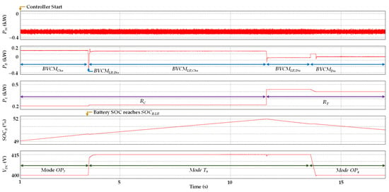
Figure 17.
Simulation result in case of load reconnection in islanded mode.
5.5. Case of Voltage Regulation by Wind Turbine Unit in Islanded Mode
Figure 18 shows the simulation result for the proposed PFCS in case of voltage regulation by the wind turbine unit in the islanded mode. Initially, the DCMG system operates with OP6 at t = 1 s, in which the wind turbine unit operates in the MPPT mode, the battery unit regulates Vdc with BVCMCha with RdB5, and all the loads are connected in the load unit. As soon as the battery SOC level reaches SOCB,Max around t = 4 s, the battery unit changes operation to idle mode with RdB3. Because this produces a Vdc rise, the DCMG operation is changed to mode T12, in which the wind turbine unit operates in WVDCM with RdW1. The wind turbine unit monitors Vdc and changes the operation mode after 5 s (around t = 9 s) to WVCM with RdW2, which results in the DCMG operation change to OP9. In this operation, the wind turbine unit regulates Vdc, the battery unit is in idle mode, and all the loads are connected.
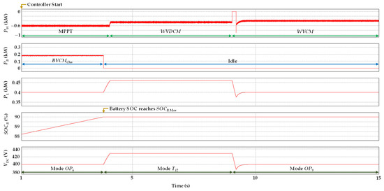
Figure 18.
Simulation result in case of voltage regulation by wind turbine unit in islanded mode.
5.6. Case of EV Unit Involvement
To demonstrate the scalability of the proposed PFCS for the decentralized DCMG system, Figure 19 shows the simulation result in the case of the EV unit connection when the battery SOC level reaches SOCB,Emg-H in the islanded mode. Initially, the wind turbine unit is in the MPPT mode, the battery unit regulates Vdc in BVCMDis with RdB4, and the EV unit is in idle mode with RdEV3. As the battery SOC level reaches SOCB,Emg-H around t = 2.5 s, the battery unit changes operation to BVCMEmg1 with RdB6 and decreases Vdc to VL2. The EV unit monitors Vdc, and changes operation to EVCMDis with RdEV4 after 100 ms to regulate Vdc back to VNom. The battery unit remains idle when the EV undertakes the regulation of Vdc to VNom.
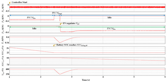
Figure 19.
Simulation result in case of EV unit connection when battery SOC level reaches SOCB,Emg-H in islanded mode.
6. Experimental Results
The decentralized DCMG experimental setup, depicted in Figure 20, is used to demonstrate the feasibility of the proposed PFCS with the system parameters in Table 11. The experiment was performed with a laboratory-scale prototype DCMG system which has a similar power rating to the studies in [12,13,14]. The experimental DCMG system comprises four power electronic converters, which interface the DC-link with the utility grid unit, battery unit, wind turbine unit, and EV unit. The utility grid unit is connected to a three-phase main grid via a Y-Δ transformer and bidirectional AC/DC converter equipped with an LCL filter. The wind turbine unit combines a PMSG with an induction machine to transmit power to the DC-link through a unidirectional AC/DC converter. The battery and EV units utilize bidirectional interleaved DC/DC converters to connect a bidirectional DC power source, serving as a battery. The magnetic contactors are used in the load unit. Power converters are implemented using a digital signal processor (DSP) TMS320F28335. The experimental tests are performed considering six scenarios: electricity price change, transition from the grid-connected to islanded mode, emergency SOC operation in the islanded mode, load reconnection in the islanded mode, voltage regulation by the wind turbine unit, and involvement of the EV unit.
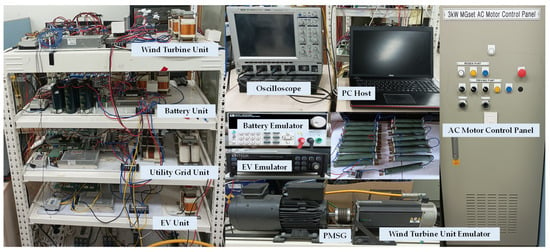
Figure 20.
Configuration of experimental decentralized DCMG test setup.
6.1. Case of Electricity Price Changes
Figure 21 shows the experimental result of the proposed PFCS for a decentralized DCMG system when the grid electricity price changes from normal to high. The DCMG system initially works in OP2, in which the wind turbine unit operates in the MPPT mode, the battery unit is in BCM mode with RdB2, and the utility grid unit regulates Vdc to VNom with RdG1. When the electricity price is changed to high, the operation is changed to T1. In this mode, the utility grid unit operates with RdB2 and regulates Vdc to VL1. The battery unit monitors Vdc, and changes operation to BDM with RdB1 in 3 s after the instant that the Vdc reduces to VL1. After 5 s from the instant the Vdc reduces to VL1, the DCMG operation is returned to OP3, in which the utility grid unit regulates Vdc back to VNom, the battery unit is in BDM mode with RdB1, and the wind turbine unit operates in the MPPT mode.
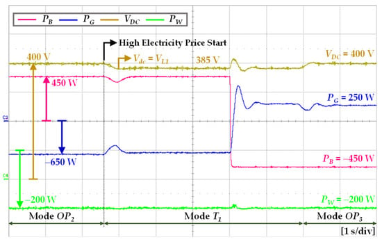
Figure 21.
Experimental result of the proposed PFCS in grid-connected mode when grid electricity price is changed from normal to high.
Figure 22 shows the experimental result of the proposed PFCS when the grid electricity price changes from high to normal. The DCMG system initially runs in OP3, in which the wind turbine unit operates in the MPPT mode, the battery is in BDM mode with RdB1, and the grid regulates Vdc to VNom with RdG1. When the electricity price is changed to normal, the operation is changed to T2. In this mode, the utility grid unit operates with RdB3 and regulates Vdc to VH1. The battery unit monitors Vdc, and changes operation to BCM with RdB2 in 18 s after that Vdc increased to VH1. In the 20 s after Vdc increased to VH1, the DCMG operation is returned to OP2, in which the utility grid unit regulates Vdc back to VNom, the battery unit is in BCM mode with RdB2, and the wind turbine unit operates in the MPPT mode.
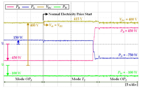
Figure 22.
Experimental result of the proposed PFCS in grid-connected mode when grid electricity price is changed from high to normal.
6.2. Case of Transition from Grid-Connected Mode to Islanded Mode
Figure 23 shows the experimental result of the proposed PFCS under the transition from the grid-connected mode to islanded mode. Initially, the DCMG system is in OP2, in which the wind turbine unit operates in the MPPT mode, the battery unit is in BCM mode with RdB2, the utility grid unit regulates Vdc to VNom with RdG1, and all the loads are connected. When the utility grid is disconnected due to a fault, the Vdc starts to decrease. The battery unit continuously monitors Vdc and changes operation to BVCMDis with RdB4 in the 10 ms after Vdc falls to VL2. As a result, the DCMG operation is changed to OP4, in which the battery regulates Vdc to VNom in the islanded mode, the wind operates in the MPPT mode, and all the loads are connected.
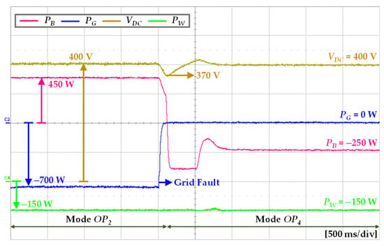
Figure 23.
Experimental result of the proposed PFCS in case of the transition from grid-connected mode to islanded mode.
6.3. Case of Emergency SOC in Islanded Mode
To verify the battery SOC management feature of the proposed PFCS, Figure 24 presents the experimental result when the battery SOC reaches SOCB,Emg-H in the islanded mode. The DCMG system initially operates in OP4, in which the wind turbine unit operates in the MPPT mode, the battery unit regulates Vdc to VNom using BVCMDis with RdB4, and all the loads are connected. As soon as the battery SOC level reaches SOCB,Emg-H in the islanded mode, the DCMG operation is changed to T5 as the battery unit changes operation to BVCMEmg1 to reduce Vdc to VL2 during 0.5 s. After that, the DCMG operation is changed again to T6, in which the battery unit maintains Vdc at VL2. The load unit monitors Vdc and triggers RNC shedding in 3 s after that Vdc is reduced. In 5 s after that Vdc is reduced to VL2, the DCMG operation is changed to OP5, in which the battery unit regulates Vdc at VNom using BVCMDis with RdB4, the wind turbine unit operates in the MPPT mode, and only RC is connected in the load unit.
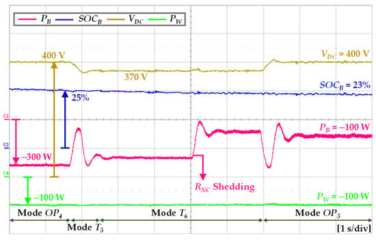
Figure 24.
Experimental result of the proposed PFCS when the battery SOC level reaches emergency case, SOCB,Emg-H in islanded mode.
6.4. Case of Load Reconnection in Islanded Mode
Figure 25 shows the experimental result of the proposed PFCS when the battery SOC level reaches load reconnection level, SOCB,LR in the islanded mode. First, the DCMG system operates in OP7, in which the wind turbine unit operates in the MPPT mode, the battery unit regulates Vdc with BVCMCha with RdB5, and the load unit only operates with RC. The battery SOC level increases with BVCMCha operation. As soon as the battery SOC level reaches SOCB,LR, the battery unit changes operation to BVCMLR,Cha with RdB8 and the DCMG starts to operate in T9 in which the battery unit increases Vdc to VH1. The load unit monitors Vdc and then reconnects RC load after 8 s. After load reconnection, the DCMG operates in steady-state OP4, in which the battery operates in BVCMDis with RdB4, the wind turbine unit operates in the MPPT mode, and all loads are connected.
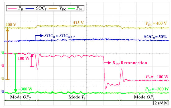
Figure 25.
Experimental result of the proposed PFCS when the battery SOC level reaches load reconnection level (SOCB,LR) in islanded mode.
6.5. Case of Voltage Regulation by Wind Turbine Unit in Islanded Mode
Figure 26 shows the experimental result of the proposed PFCS when the wind turbine unit regulates Vdc in the islanded mode. Initially, the DCMG system operates in OP6, in which the wind turbine unit operates in the MPPT mode, the battery unit regulates Vdc in BVCMCha with RdB5, and all loads are connected in the load unit. As soon as the battery SOC level reaches SOCB,Max, the battery unit operation is changed to idle mode with RdB3. Because it results in the wind turbine power being higher than the load requirements, Vdc increases, and the wind turbine unit operates in WVDCM with RdW1. Then, the DCMG operation is changed to T12. As shown in Figure 10b, 5 s after the instant of Vdc increase, the wind turbine unit changes the operation to WVCM with RdW2, which changes the DCMG operation to OP9. In this mode, the wind turbine unit regulates Vdc, the battery unit is in idle mode, and all loads are connected.
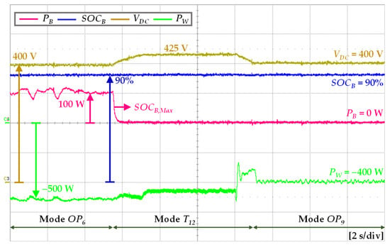
Figure 26.
Experimental result of the proposed PFCS in case of voltage regulation by wind turbine unit in islanded mode.
6.6. Case of EV Unit Involvement
To demonstrate the scalability of the proposed PFCS of the decentralized DCMG system, Figure 27 shows the experimental result in case of the EV unit connection specifically when the battery SOC level reaches SOCB,Emg-H in the islanded mode. Initially, the wind turbine unit is in the MPPT mode, the battery unit regulates Vdc in BVCMDis with RdB4, and the EV unit is in idle mode with RdEV3. When the battery SOC level reaches SOCB,Emg-H, the battery unit operation is changed to BVCMEmg1 with RdB6 and Vdc is decreased to VL2. By monitoring Vdc level, the EV unit changes operation to EVCMDis with RdEV4 100 ms after the instant that Vdc is decreased to VL2, as shown in Figure 12c. The Vdc is then gradually increased to VNom as the EV unit injects the maximum power. It is confirmed from this result that the proposed PFCS exhibits the scalable feature because the EV unit can operate as additional ESS to support the battery when the battery SOC level approaches a low level.
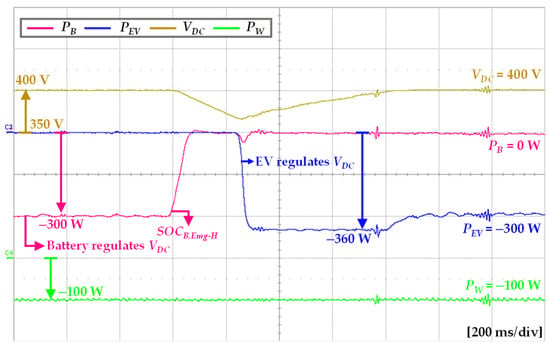
Figure 27.
Experimental result of the proposed PFCS in case of EV unit involvement.
7. Conclusions
With the aim of enhancing the reliability and optimizing the DCMG operation, this paper has presented a PFCS for a decentralized DCMG system. The proposed PFCS utilizes the transition mode operations to transmit the information on the DCMG system to other power units without using additional DCLs. During the transition operation modes, the transmitting power unit adjusts the DC-link voltage level, while the receiving power unit continuously monitors the DC-link voltage with the predetermined intervals. If uncertain conditions arise in a specific power unit, this power unit activates the transition operation mode to propagate this information to all power units in the DCMG system. After this uncertain condition is acknowledged by all power units, the DCMG operation is switched back from the transition operation mode to the optimal steady-state operation. The proposed PFCS greatly improves the flexibility of the decentralized DCMG system even under various factors such as electricity price change, grid availability, battery SOC level, and wind power variation. The DC-link voltage can be effectively maintained at the nominal value at steady-state conditions by the proposed PFCS regardless of the grid-connected or islanded mode. The DCMG system reliability is also improved by incorporating the battery SOC management strategy. Furthermore, the scalability issue of the DCMG system is also studied by considering an EV unit as an additional ESS in the DCMG system. Simulation and experimental results under various conditions have been presented to verify the performance of the proposed PFCS. The results clearly confirm the reliability and flexibility of the proposed PFCS.
Author Contributions
M.A.M.J., D.T.T. and K.-H.K. conceived the main concept of the DC microgrid control structure and developed the entire system. M.A.M.J. and D.T.T. carried out the research and analyzed the numerical data with guidance from K.-H.K.; M.A.M.J., D.T.T. and K.-H.K. collaborated in the preparation of the manuscript. All authors have read and agreed to the published version of the manuscript.
Funding
This research was supported by Basic Science Research Program through the National Research Foundation of Korea (NRF) funded by the Ministry of Education (NRF-2019R1A6A1A03032119). This work was supported by the National Research Foundation of Korea (NRF) grant funded by the Korea government (MSIT) (NRF-2022R1F1A1064350).
Institutional Review Board Statement
Not applicable.
Informed Consent Statement
Not applicable.
Data Availability Statement
Data sharing is not applicable to this article.
Conflicts of Interest
The authors declare no conflict of interest.
References
- Carpintero-Rentería, M.; Santos-Martín, D.; Guerrero, J.M. Microgrids literature review through a layers structure. Energies 2019, 12, 4381. [Google Scholar] [CrossRef]
- Ansari, S.; Chandel, A.; Tariq, M. A comprehensive review on power converters control and control strategies of AC/DC microgrid. IEEE Access 2020, 9, 17998–18015. [Google Scholar] [CrossRef]
- Al-Ismail, F.S. DC microgrid planning, operation, and control: A comprehensive review. IEEE Access 2021, 9, 36154–36172. [Google Scholar] [CrossRef]
- Ensermu, G.; Bhattacharya, A.; Panigrahy, N. Real-time simulation of smart DC microgrid with decentralized control system under source disturbances. Arab. J. Sci. Eng. 2019, 44, 7173–7185. [Google Scholar] [CrossRef]
- Zhou, L.; Zhang, Y.; Lin, X.; Li, C.; Cai, Z.; Yang, P. Optimal sizing of PV and BESS for a smart household considering different price mechanisms. IEEE Access 2018, 6, 41050–41059. [Google Scholar] [CrossRef]
- Espina, E.; Llanos, J.; Burgos-Mellado, C.; Cárdenas-Dobson, R.; Martínez-Gómez, M.; Sáez, D. Distributed control strategies for microgrids: An overview. IEEE Access 2020, 8, 193412–193448. [Google Scholar] [CrossRef]
- Lopes, J.A.P.; Moreira, C.L.; Madureira, A.G. Defining control strategies for microgrids islanded operation. IEEE Trans. Power Syst. 2006, 21, 916–924. [Google Scholar] [CrossRef]
- Wang, H.; Fang, H.; Yu, X.; Liang, S. How real time pricing modifies chinese households’ electricity consumption. J. Clean. Prod. 2018, 178, 776–790. [Google Scholar] [CrossRef]
- Renfang, L.; Luping, S.; Sidai, G. The stepwise pricing mechanism research of residents’ living power. Energy Procedia 2011, 5, 1371–1376. [Google Scholar] [CrossRef][Green Version]
- Dai, Y.; Gao, Y.; Gao, H.; Zhu, H. Real-time pricing scheme based on stackelberg game in smart grid with multiple power retailers. Neurocomputing 2017, 260, 149–156. [Google Scholar] [CrossRef]
- Dragičević, T.; Lu, X.; Vasquez, J.C.; Guerrero, J.M. DC microgrids—Part I: A review of control strategies and stabilization techniques. IEEE Trans. Power Electron. 2016, 31, 4876–4891. [Google Scholar]
- Habibullah, A.F.; Padhilah, F.A.; Kim, K.-H. Decentralized control of DC microgrid based on droop and voltage controls with electricity price consideration. Sustainability 2021, 13, 11398. [Google Scholar] [CrossRef]
- Padhilah, F.A.; Kim, K.-H. A power flow control strategy for hybrid control architecture of DC microgrid under unreliable grid connection considering electricity price constraint. Sustainability 2020, 12, 7628. [Google Scholar] [CrossRef]
- Habibullah, A.F.; Kim, K.-H. Decentralized power management of DC microgrid based on adaptive droop control with constant voltage regulation. IEEE Access 2022, 10, 129490–129504. [Google Scholar] [CrossRef]
- Mehdi, M.; Kim, C.H.; Saad, M. Robust centralized control for dc islanded microgrid considering communication network delay. IEEE Access 2020, 8, 77765–77778. [Google Scholar] [CrossRef]
- Dehkordi, N.M.; Sadati, N.; Hamzeh, M. Distributed robust finite-time secondary voltage and frequency control of islanded microgrids. IEEE Trans. Power Syst. 2017, 32, 3648–3659. [Google Scholar] [CrossRef]
- Li, X.; Jiang, W.; Wang, J.; Wang, P.; Wu, X. An autonomous control scheme of global smooth transitions for bidirectional DC-DC converter in DC microgrid. IEEE Trans. Energy Convers. 2021, 36, 950–960. [Google Scholar] [CrossRef]
- Li, J.; Liu, Y.; Wu, L. Optimal operation for community-based multi-party microgrid in grid-connected and islanded modes. IEEE Trans. Smart Grid 2018, 9, 756–765. [Google Scholar] [CrossRef]
- Xia, Y.; Wei, W.; Peng, Y.; Yang, P.; Yu, M. Decentralized coordination control for parallel bidirectional power converters in a grid-connected DC microgrid. IEEE Trans. Smart Grid 2018, 9, 6850–6861. [Google Scholar] [CrossRef]
- Dragicevic, T.; Wu, D.; Shafiee, Q.; Meng, L. Distributed and decentralized control architectures for converter-interfaced microgrids. Chin. J. Electr. Eng. 2017, 3, 41–52. [Google Scholar]
- Shirkhani, M.; Tavoosi, J.; Danyali, S.; Sarvenoee, A.K.; Abdali, A.; Mohammadzadeh, A.; Zhang, C. A review on microgrid decentralized energy/voltage control structures and methods. Energy Rep. 2023, 10, 368–380. [Google Scholar] [CrossRef]
- Li, Z.; Shahidehpour, M.; Aminifar, F. Cybersecurity in distributed power systems. Proc. IEEE 2017, 105, 1367–1388. [Google Scholar] [CrossRef]
- Gu, Y.; Xiang, X.; Li, W.; He, X. Mode-adaptive decentralized control for renewable dc microgrid with enhanced reliability and flexibility. IEEE Trans. Power Electron. 2014, 29, 5072–5080. [Google Scholar] [CrossRef]
- Guerrero, J.M.; Vasquez, J.C.; Matas, J.; De Vicuña, L.G.; Castilla, M. Hierarchical control of droop-controlled AC and DC microgrids—A general approach toward standardization. IEEE Trans. Ind. Electron. 2010, 58, 158–172. [Google Scholar] [CrossRef]
- Xu, Q.; Xiao, J.; Hu, X.; Wang, P.; Lee, M.Y. A decentralized power management strategy for hybrid energy storage system with autonomous bus voltage restoration and state-of-charge recovery. IEEE Trans. Ind. Electron. 2017, 64, 7098–7108. [Google Scholar] [CrossRef]
- Tuckey, A.; Zabihi, S.; Round, S. Decentralized control of a microgrid. In Proceedings of the 19th European Conference on Power Electronics and Applications, Warsaw, Poland, 11–14 September 2017. [Google Scholar]
- Khorsandi, A.; Ashourloo, M.; Mokhtari, H. A decentralized control method for a low-voltage DC microgrid. IEEE Trans. Energy Convers. 2014, 29, 793–801. [Google Scholar] [CrossRef]
- Gao, F.; Kang, R.; Cao, J.; Yang, T. Primary and secondary control in DC microgrids: A review. J. Mod. Power Syst. Clean Energy. 2019, 7, 227–242. [Google Scholar] [CrossRef]
- Nguyen, T.V.; Kim, K.-H. Power flow control strategy and reliable DC-link voltage restoration for DC microgrid under grid fault conditions. Sustainability 2019, 11, 3781. [Google Scholar] [CrossRef]
- Yu, Y.; Liu, G.-P.; Huang, Y.; Guerrero, J.M. Distributed data-driven secondary regulation for the conflict between voltage recovery and accurate current sharing in DC microgrids. IEEE Trans. Power Electron. 2023, 38, 9617–9634. [Google Scholar] [CrossRef]
- Dogger, J.D.; Roossien, B.; Nieuwenhout, F.D.J. Characterization of li-ion batteries for intelligent management of distributed grid-connected storage. IEEE Trans. Energy Convers. 2010, 26, 256–263. [Google Scholar] [CrossRef]
- Ayodele, T.R.; Ogunjuyigbe, A.S.O.; Akpeji, K.O.; Akinola, O.O. Prioritized rule based load management technique for residential building powered by PV/battery system. Eng. Sci. Technol. Int. J. 2017, 20, 859–873. [Google Scholar] [CrossRef]
- Xu, Y.; Liu, C.-C.; Schneider, K.P.; Tuffner, F.K.; Ton, D.T. Microgrids for service restoration to critical load in a resilient distribution system. IEEE Trans. Smart Grid 2016, 9, 426–437. [Google Scholar] [CrossRef]
- Gao, H.; Chen, Y.; Xu, Y.; Liu, C.-C. Resilience-oriented critical load restoration using microgrids in distribution systems. IEEE Trans. Smart Grid 2016, 7, 2837–2848. [Google Scholar] [CrossRef]
Disclaimer/Publisher’s Note: The statements, opinions and data contained in all publications are solely those of the individual author(s) and contributor(s) and not of MDPI and/or the editor(s). MDPI and/or the editor(s) disclaim responsibility for any injury to people or property resulting from any ideas, methods, instructions or products referred to in the content. |
© 2023 by the authors. Licensee MDPI, Basel, Switzerland. This article is an open access article distributed under the terms and conditions of the Creative Commons Attribution (CC BY) license (https://creativecommons.org/licenses/by/4.0/).