Article

Development of Energy-Saving Battery Pre-Cooling System for Electric Vehicles

Department of Mechanical and Energy Engineering, National Chiayi University, Chiayi 600, Taiwan
*
Author to whom correspondence should be addressed.
Sustainability 2023, 15(17), 13182; https://doi.org/10.3390/su151713182
Submission received: 30 June 2023 / Revised: 21 August 2023 / Accepted: 31 August 2023 / Published: 1 September 2023
(This article belongs to the Section Sustainable Transportation)

Abstract

:
The performance, lifetime, and safety of electric vehicle batteries are strongly dependent on their temperature. Consequently, effective and energy-saving battery cooling systems are required. This study proposes a secondary-loop liquid pre-cooling system which extracts heat energy from the battery and uses a fin-and-tube heat exchanger to dissipate this energy to the ambient surroundings. The liquid then passes through a chiller to complete the cooling loop. The air-conditioning system is also used to cool the battery only if the temperature of the cooling water exceeds the maximum permissible temperature. The cooling load of the air-conditioning system is thus greatly reduced. The feasibility of the proposed cooling system is demonstrated experimentally under four simulated seasonal environmental conditions, namely high summer (35 °C), mean summer (30 °C), spring and fall (20 °C), and winter (7 °C). The results show that the pre-cooling system can dissipate 1000 W of battery heat in high summer, 2000 W in low summer, 3167 W in spring and fall, and more than 4000 W in winter. In other words, the pre-cooling system greatly reduces the cooling load of the air-conditioning system, and hence significantly reduces its energy consumption.

1. Introduction

Electric vehicles (EVs) are an important development goal of many car manufacturers nowadays. Since the main source of power in such vehicles is a motor rather than an engine, the storage capacity and discharge performance of the battery are crucial concerns in the development process. However, due to the long-term and high-power discharge behavior of the battery during normal driving conditions, the amount of heat generated by the battery is considerable. When the internal temperature reaches a certain critical value, the battery function is severely impaired, and, in extreme cases, fire may occur [1]. Thus, the development of energy storage systems with high mileage, fast charging and discharging, and high performance [2,3] properties poses a significant challenge to automotive engineers.
Rechargeable lithium-ion (Li-ion) batteries have attracted significant attention as energy storage devices for EVs in recent years due to their high energy density, high specific power, light weight, low self-discharge rate, superior recyclability, and long cycle life. Compared with other rechargeable batteries, such as lead–acid, nickel–cadmium (Ni-Cd), and nickel–metal hydride (Ni-MH) [4,5], Li-ion batteries also have the advantage of no memory effect [6,7]. However, as with all battery systems, the lifetime and safety of Li-ion batteries are greatly reduced at excessively high or low temperatures [8]. For example, according to Sato (2001) [1], the charging efficiency and battery life of Li batteries both decrease as their temperature increases beyond 50 °C. Pesaran (2002) [9] reported that the optimal operating temperature for lead–acid batteries, NiMH batteries, and Li-ion batteries is around 0 to 40 °C. The same group (2013) [10] later showed that, for Li-ion batteries, the maximum temperature difference between adjacent battery cells should be less than 5 °C in order to avoid adverse performance effects.
Li-ion batteries require an effective battery thermal management system (BTMS) to maintain an appropriate temperature range with minimal thermal gradients and an improved battery performance [11]. BTMSs control the temperature of the battery by using simple heat transfer methods to remove the excess heat from the battery in order to reduce its temperature. Commercial battery cooling systems for EVs can be broadly classified into two types depending on the medium used to perform cooling, namely ambient or air-conditioned air, or liquid (e.g., refrigerant). Rao and Wang (2011) [12] indicated that heat dissipation methods for batteries can be divided into passive heat dissipation methods, in which only the ambient temperature is employed to perform heat dissipation, and active heat dissipation methods, in which certain built-in resources are used to prompt heat dissipation. Wang et al. (2016) [13] further divided battery cooling methods into four types: air cooling, liquid cooling, phase change material cooling, and heat pipe cooling.
BTMSs using air as a medium have long been applied in EVs due to their relatively simple design, which reduces production and maintenance costs. However, air cooling systems have several practical disadvantages: (1) the heat capacity of air is relatively low, (2) the use of multiple blowers to introduce a sufficient amount of cooling air may cause noise issues, and (3) many air ducts and fins are physically bulky and occupy excessive space. Consequently, many researchers have attempted to enhance the heat dissipation capacity of air cooling systems by improving the air duct design and battery arrangement. Park (2013) [14] conducted numerical simulations to analyze five different types of manifolds. The results showed that the optimal airflow configuration was obtained when air was blown in from the bottom of the battery pack and flowed out from the top of the pack. However, the air flow resulted in a non-uniform heat dissipation effect. Broadly speaking, the heat dissipation effect was improved when the air inlet and outlet were designed on the same side. Chen et al. (2017) [15] studied the effect of the battery cell spacing on the heat dissipation performance and found that as the cell spacing decreases, the temperature and the temperature difference of the battery pack are both reduced effectively. However, the decrease of the cell spacing increases the power consumption of the system significantly.
Compared with air-cooled systems, liquid cooling systems utilize liquid coolants with a higher mass flow rate, higher heat capacity, and higher heat transfer rate. The development of liquid-based BTMSs has received extensive research attention. Jarrett et al. (2011) [16] and Jin et al. (2014) [17] enhanced the overall heat dissipation effect by improving the geometric structure (e.g., channel size and path) of the liquid cooling system. Huo et al. (2014) [18] investigated the effects of the number of cooling liquid channels, flow direction, and mass flow rate on the temperature distribution within the battery pack. Malik et al. (2017) [19] designed a heat dissipation module to analyze the discharge rate and liquid temperature of EV batteries. The results showed that the discharge capacity of the battery pack increased with an increasing coolant temperature and reached a maximum value of 19.11 Ah at a 1C discharge rate for a coolant temperature of 40 °C.
Kim et al. [20] classified BTMSs into two categories depending on whether or not they employed a vapor compression cycle (VCC). The authors further divided VCC and non-VCC cooling systems into six categories according to their heat dissipation method, namely (1) cabin air cooling, (2) secondary-loop liquid cooling, (3) direct refrigerant two-phase cooling for VCC systems, and (4) phase change material cooling, (5) heat pipe cooling, and (6) thermoelectric cooling for non-VCC systems. Most EVs use the integration of a BTMS and VCC [21,22] to cool the battery and provide a comfortable environment for the passengers. Among methods (1)–(3) above, the cabin air cooling method dissipates the battery heat by blowing cabin air directly into the interior of the battery. Meanwhile, secondary-loop liquid cooling systems separate the battery cooling loop from the air-conditioning system and use a heat exchanger to transfer the heat between the two loops. Finally, in direct refrigerant two-phase cooling systems, the air-conditioning system and battery cooling system share the same refrigerant loop, and the air-conditioned refrigerant is used to simultaneously cool both the vehicle cabin and the battery.
However, VCC cooling methods suffer from a fundamental problem. In particular, when the weather is hot and the ambient temperature is high, or when the battery is discharged with high power and generates significant heat, the air-conditioning system is required to provide additional cooling capacity to prevent the battery from overheating. This increases the cooling load of the air-conditioning system, which not only increases its energy consumption, but may also result in an uneven distribution of the air-conditioning cooling capacity, thereby affecting the thermal comfort of the passengers. Krüger et al. (2012) [23] investigated the impact of the battery cooling system on the air-conditioning system at ambient temperatures of 25 °C and 45 °C, respectively, and found that the cooling system increased the overall energy consumption by 11% and seriously impacted the comfort of the passengers at higher temperatures. Tian et al. (2018) [24] examined the interaction between passenger thermal comfort and the battery cooling system and showed that the performance of the air conditioner was significantly impacted in summer conditions since part of the refrigerant was distributed to the battery cooling circuit. Cen and Jiang (2020) [25] developed a control system to distribute the mass flow rate of the refrigerant between the battery cooling system and the air-conditioning evaporator, respectively. The results showed that a higher refrigerant mass flow rate into the battery module avoided superheating of the refrigerant and achieved a maximum temperature difference within the battery module of less than 2 °C.
As stated in the papers above [23,24,25], the battery cooling system increased the overall energy consumption by 11% and seriously impacted the comfort of the passengers at higher temperatures. To reduce the air-conditioning cooling load caused by battery cooling, the present study proposes a secondary-loop liquid cooling system to pre-cool the battery. As shown in Figure 1, the water-cooling system first extracts the heat generated by the battery and then uses a fin-and-tube heat exchanger to dissipate the heat to the environment. The water is then passed through a chiller to complete the loop. Notably, in the proposed system, the air-conditioning system is used to help dissipate the battery heat only when the temperature difference between the battery and cooling water exceeds the maximum permissible temperature. Consequently, the air-conditioning system’s cooling load, and hence the energy consumption, is significantly reduced.
The details of the proposed system are shown in Figure 1. The system consists of two liquid loops, namely an air-conditioning refrigerant loop (marked with blue arrows) and a battery water cooling loop (marked with red arrows). In the air-conditioning loop, the refrigerant is compressed and driven through a condenser, where it releases heat and condenses. The low-temperature, low-pressure refrigerant then passes through an expansion valve and enters a three-way valve, where it subsequently flows through an evaporator to cool the cabin air, or is diverted to a chiller if necessary to cool the battery cooling water. In both cases, the refrigerant flows back to the compressor to complete the cooling cycle. In the battery cooling water loop, after the cooling water absorbs the heat from the battery through a cooling plate, it flows through the fin-and-tube radiator to dissipate the heat to the ambient surroundings and then passes through the chiller to undergo cooling to the target temperature.

2. Experimental Apparatus

Figure 2 shows the experimental setup used in the present study to evaluate the feasibility of the proposed secondary-loop liquid cooling system. In the cooling water loop (shown in red), the water was pressurized by a water pump and flowed over a heater mimicking the battery to absorb heat. It was then passed to a radiator to dissipate the heat and then flowed through a chiller and returned to the heater to complete the cycle.
The aim of the experimental investigation was to determine the heat dissipation capacity of the pre-cooling water cooling system in the absence of any assistance from the air conditioner/refrigerant cooling system. Thus, the chiller was turned off in the experimental trials. Furthermore, to evaluate the performance of the proposed pre-cooling system under realistic temperature conditions, the experiments were performed under four different ambient temperature settings, namely (1) high summer (35 °C), (2) mean summer (30 °C), (3) spring and fall (20 °C), and (4) winter (7 °C).
Figure 3 presents a photograph of the experimental arrangement, consisting of a cooling water loop, a radiator and fan module, a heater, a temperature and humidity test chamber, measuring components, and a data acquisition system. The details of the main experimental components are described below.

2.1. Cooling Water Loop

The experiments used RO-filtered water as the cooling water. Thermocouples were buried at the inlets and outlets of the water pump, radiator, and heater, respectively, to measure the water temperature at various points in the cooling water loop. In addition, an ultrasonic flow meter was installed at the outlet of the heater to measure the cooling water mass flow rate. All of the water pipes were wrapped in insulating material to minimize the effects of heat exchange between the ambient surroundings and the pipe wall on the measurement results. A fairing was installed at the air inlet of the cooling fan to ensure an even distribution of the air flow over the radiator, and a total of six thermocouples were deployed at the fan inlet and fan outlet to measure the air temperature. Finally, the test equipment was placed in a temperature- and humidity-controlled chamber in order to establish the temperature and humidity conditions described above.

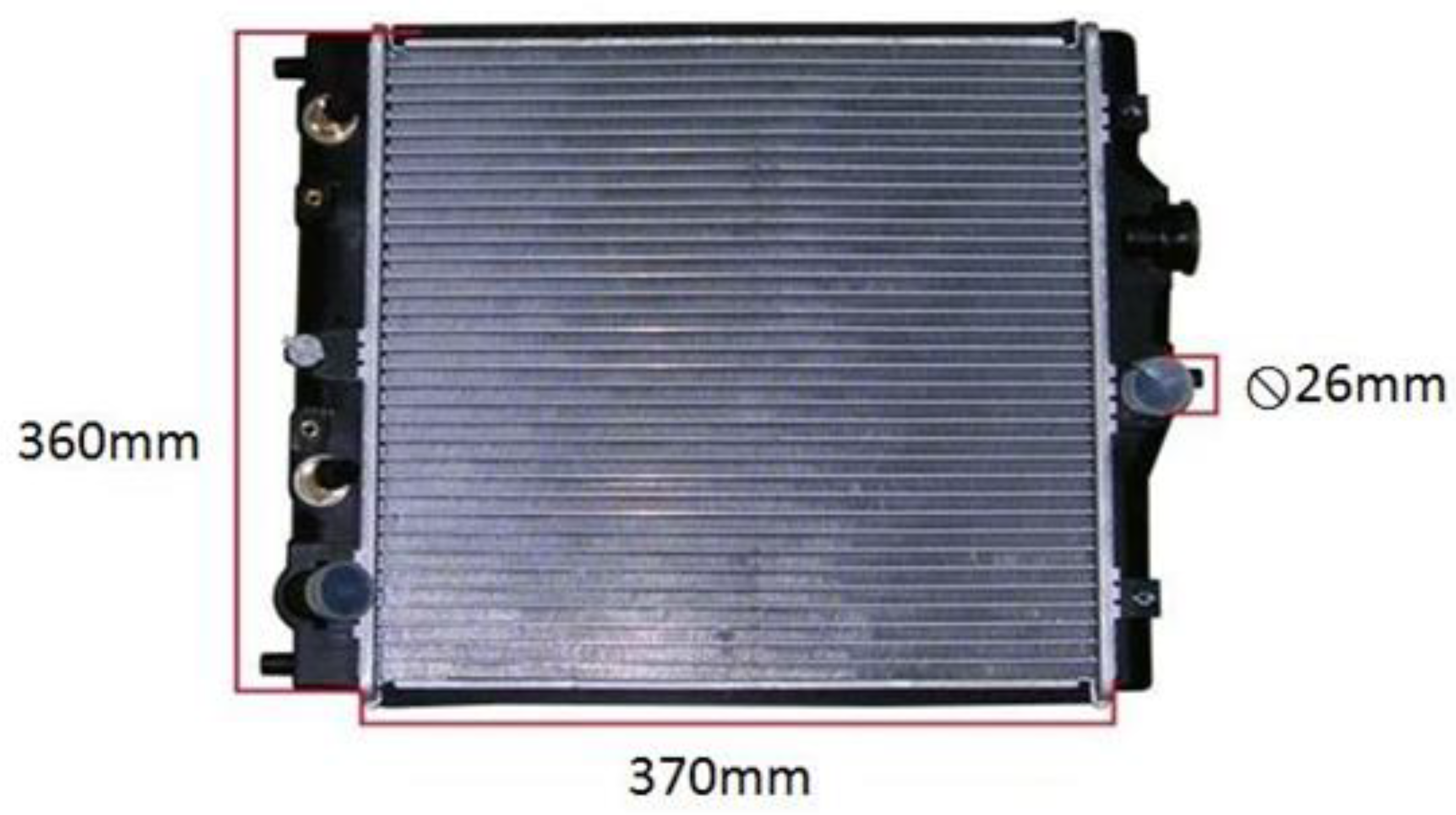
2.2. Radiator and Fan Module

The radiator had the form of a commercially available automotive engine double-row aluminum fin-and-tube heat exchanger with a high heat transfer performance, small size, and light weight (see Figure 4). The matching cooling fan is shown in Figure 5, where the corresponding specification is listed in Table 1.

2.3. Heater

In the experiments, the heat generated by the battery was simulated using an electric heater with the specification shown in Table 2. A variable resistor and solid-state relay were connected to the power supply side to achieve a linear control of the heating power in the range of 0–8800 W. Wang et al. (2016) [13] reported that for a battery with a capacity of 60 kWh, the heat generation rate reached as much as 3.2 kW under a discharge power of 60 kW. For safety reasons, the maximum heat generation rate of the present heater was limited to 4000 W during the experiments, where this value was deemed to be sufficient to simulate the actual heat generation rate of a real EV battery [13].

2.4. Temperature and Humidity Test Chamber

The specification details of the test chamber used to control the temperature and humidity conditions in the present experiments are shown in Table 3.
In accordance with the Taiwan CNS14464 standard 「Non-ducted Air Conditioners and Heat Pumps—Testing and Rating for Performance」 [26], the high summer test condition was specified as a dry bulb temperature of 35 °C and a wet bulb temperature of 24 °C. According to statistical data obtained from the official website of the Taiwan Central Weather Bureau [27], the average summer temperature in Taiwan is around 30 °C (statistical period 1981–2010). Thus, the mean summer test condition was set as a dry bulb temperature of 30 °C and a relative humidity of 80%. The winter test condition was based on the Japanese Industrial JIS C 9220 standard for heat pump water heaters [28], namely a dry bulb temperature of 7 °C and a wet bulb temperature of 6 °C. According to the official website of the Taiwan Central Weather Bureau [27], the average temperature in Taiwan during the spring and fall seasons is around 20 °C (statistical period 1981–2010). Therefore, the spring and fall test condition was specified as a temperature of 20 °C and a relative humidity of 80% (i.e., a wet bulb temperature of 17.7 °C). The test conditions for the four cases are summarized in Table 4.

2.5. Measuring Equipment

The mass flow rate of the cooling water in the experimental setup was measured using an ultrasonic flowmeter (MICRONICS; model PF330) with an applicable pipe size of 3/4~240″ (with different probes), an accuracy of ±1%, and a minimum sensitivity of 0.001 m/s. The air volume flow rate was measured by a TSI-8380 air capture hood with dimensions of 610 mm × 610 mm (length × width), a measurement range of 42~4520 m 3 / h , and an accuracy of ±12 m 3 / h or ±3% of the reading (whichever was greater). Finally, the temperature in the cooling system was measured using K-type thermocouple thermometers with a working range of −200 °C to +1000 °C.

2.6. Data Acquisition System

The output signals from the flow meter, K-type thermocouples, and power meter were digitalized, captured by an MV2000 recorder (YOKOGAWA Company, Tokyo, Japan), and displayed in real time on a monitor. All of the captured data were stored to disk for post-processing by DAQSTANDARD software (DXA120).

2.7. Data Analysis

The heat transfer rates on the water side and air side were computed from the measurement points in Figure 2, respectively, as follows:
Q H X = m ˙ w C p T w , i n T w , o u t
Q H X = m ˙ a i r C p , a i r T a i r , i n T a i r , o u t
where Q H X is the heat transfer rate, m ˙ w is the water mass flow rate measured by the flow meter, C p is the specific heat of water (i.e., 4180 kJ/kg-K), T w , i n is the water inlet temperature of the radiator, and T w , o u t is the water outlet temperature of the radiator. In addition, m ˙ a i r is the air mass flow rate measured by the TSI-8380 air capture hood, C p , a i r is the specific heat of air (i.e., 1.007 kJ/kg-K), T a i r , i n is the air inlet temperature of the radiator, and T a i r , o u t is the air outlet temperature of the radiator.
Note that the heat transfer rate on the water side is theoretically the same as the heat transfer rate on the air side. Therefore, the closer the calculated results on both sides are, the more accurate the experiment is.

2.8. Uncertainty Analysis

Table 5 shows the accuracies of the various measuring components in the experimental system.
The uncertainty of the experimental measurements was calculated as [29]
W R = R X 1 W 1 2 + R X 2 W 2 2 + + R X n W n 2 1 2 ,
where R is the experimental target parameter, W R is the uncertainty result that the experiment may eventually produce, X 1 to X n are parameters that may cause errors in the experiment, and W 1 to W n are the maximum error values of the corresponding parameters.
From Equation (3), the uncertainty of the heat transfer on the water side of the radiator was determined to be approximately 2.1 to 7.5%, while that on the air side of the radiator was estimated to be around 3.3 to 5.6%.

3. Results and Discussion

According to previous studies, the average value of the upper limit of the EV battery temperature is around 45 °C [1,2,9]. Furthermore, the temperature difference between the cooling water and the battery is generally about 2 °C [2]. Thus, in the pre-cooling system proposed in the present study, the aim is to control the cooling water outlet temperature of the heater (i.e., the battery cooling water outlet temperature) to be less than or equal to 43 °C. In other words, if the pre-cooling system can control the outlet temperature of the cooling water to be less than or equal to this value, there is no need to activate the air conditioner/refrigerant cooling system to assist in the heat dissipation process. Accordingly, as described above, in order to determine the maximum heat dissipation capacity of the pre-cooling system under different environmental temperature conditions, the air conditioner/refrigerant heat dissipation system was not activated during the experiments (i.e., the chiller was not turned on).

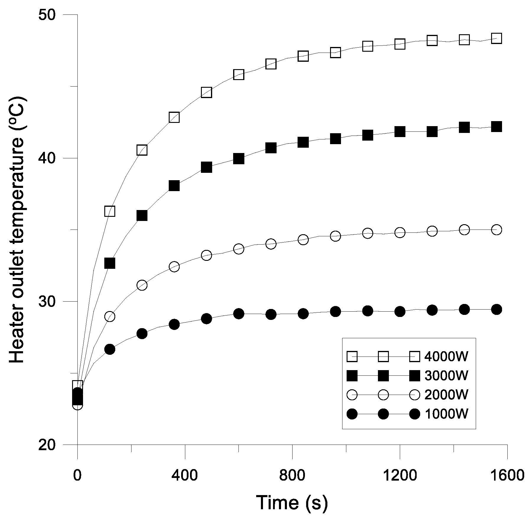
3.1. High Summer Experimental Results

Figure 6a,b show the heat dissipation rates on the cooling water side and air side of the radiator, respectively, under two different heating conditions (500 W and 1000 W) and an ambient temperature of 35 °C. (Note that the heating powers were selected based on a preliminary experiment, which revealed that the radiator achieved a stable heat dissipation performance under these conditions.) It is seen that the heat transfer on the water side is roughly equal to that on the air side for both heating powers. From inspection, the difference between them is within ±5%, which lies within the uncertainty range computed in Section 2.8.
Figure 7 shows the temperature of the cooling water at the exit of the heater under heating powers of 500 W and 1000 W, respectively. The steady-state values of the outlet temperature are 41.2 °C and 43.0 °C, respectively. In other words, when the environmental temperature is 35 °C, the pre-cooling system has a heat dissipation capacity of 1000 W, and the chiller needs to be activated only when the heating value exceeds this value. Thus, the cooling load of the air-conditioning system can be reduced by up to 1000 W.

3.2. Mean Summer Experimental Results

Figure 8a,b show the cooling water side and air side heat dissipation rates of the radiator under an environmental temperature of 30 °C and heating powers of 1000 W and 2000 W, respectively. Note that the heating powers were again specifically chosen based on an observation of the stability of the heat dissipation of the radiator. The difference between the heat transfer rates on the cooling water side and air side, respectively, is less than ±5%, which is again within the calculated range of measurement uncertainty.
Figure 9 shows the temperature of the cooling water at the outlet of the heater under the two different heating powers. Under steady-state conditions, the outlet temperature of the heater is equal to 38 °C and 43.0 °C for heating powers of 1000 W and 2000 W, respectively. That is, for an environmental temperature of 30 °C, the heat dissipation capacity of the pre-cooling system is 2000 W, and the chiller needs to be activated only when the heating value exceeds this value. In other words, the cooling load of the air-conditioning system is eased by up to 2000 W.

3.3. Spring and Fall Experimental Results

Figure 10a,b show the cooling water side and air side heat dissipation rates of the radiator, respectively, under heating powers of 1000, 2000, 3000, and 4000 W and an environmental temperature of 20 °C. For each heating power, the difference between the water side and air side heat transfer rates is less than ±5%, which lies within the calculated uncertainty range.
Figure 11 shows the cooling water outlet temperature of the heater under the four different heating conditions. For heating powers of 1000 W, 2000 W, and 3000 W, respectively, the corresponding steady-state outlet temperatures are 30 °C, 35 °C, and 42 °C. For the highest heating power of 4000 W, the outlet temperature of the heater reaches 48 °C, and is thus higher than the target value of 43 °C. Based on interpolation, a heater outlet temperature of 43 °C requires the heater to achieve a maximum heating capacity of around 3167 W (i.e., x 3000 4000 3000 = 43 42 48 42 ,   x = 3167). In other words, for an environmental temperature of 20 °C, the heat dissipation capacity of the pre-cooling system is 3167 W, and the cooling load of the air-conditioning system is thus also reduced by up to 3167 W.

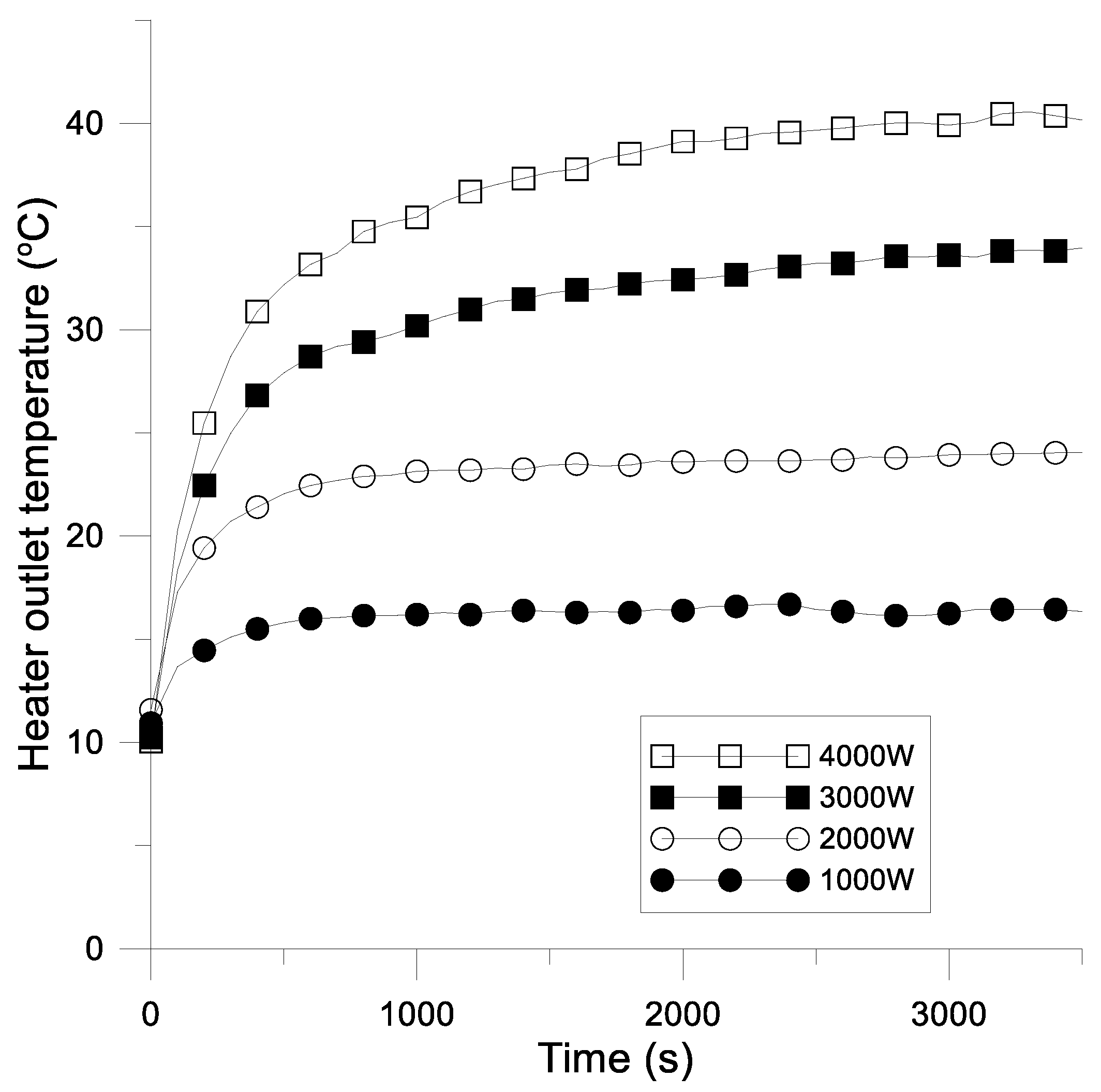
3.4. Winter Experimental Results

Figure 12a,b show the cooling water side and air side heat dissipation rates of the radiator, respectively, under heating powers of 1000, 2000, 3000, and 4000 W and an environmental temperature of 7 °C. The difference between the heat transfer rates on the two sides of the radiator is less than ±5% and is thus within the calculated uncertainty range.
Figure 13 shows the cooling water outlet temperature of the heater under the four different heating conditions. For heating powers of 1000 W, 2000 W, 3000 W, and 4000 W, respectively, the corresponding steady state outlet temperatures of the heater are 16.5 °C, 24.0 °C, 33.5 °C, and 39.9 °C. In other words, for an environmental temperature of 7 °C, the heat dissipation capacity of the pre-cooling system is more than 4000 W. Thus, the air conditioning load can be reduced by up to 4000 W.
In cold weather (7 °C), the cooling fan of the pre-cooling system can be turned off, and the heat absorbed from the battery can be provided to the air-conditioning system as the heat source required for heating. Thus, presuming that the heat generated by the battery can be recovered, the electric energy consumed by the air conditioner for heating purposes can also be saved.
Table 6 shows the energy-saving effect of the proposed battery pre-cooling system compared with VCC cooling [23,24] in different climates. According to Tien et al. [24] and Chang et al. [30], the COP of the A/C system of EV is around 2–3. Therefore, we used COP = 2.5 for calculating the energy-saving effect of the A/C system. From Table 6, it can be seen that the energy-saving effect is about 400–1794 W. The average value is about 888 W.

4. Conclusions

This study has proposed a secondary-loop liquid cooling system for pre-cooling the battery in EV vehicles, thereby reducing the cooling load imposed on the air-conditioning system. The performance of the proposed system has been evaluated by conducting heat dissipation tests under four environmental temperature conditions, namely high summer (35 °C), mean summer (30 °C), spring and fall (20 °C), and winter (7 °C). The contributions and experimental findings of this study can be summarized as follows:
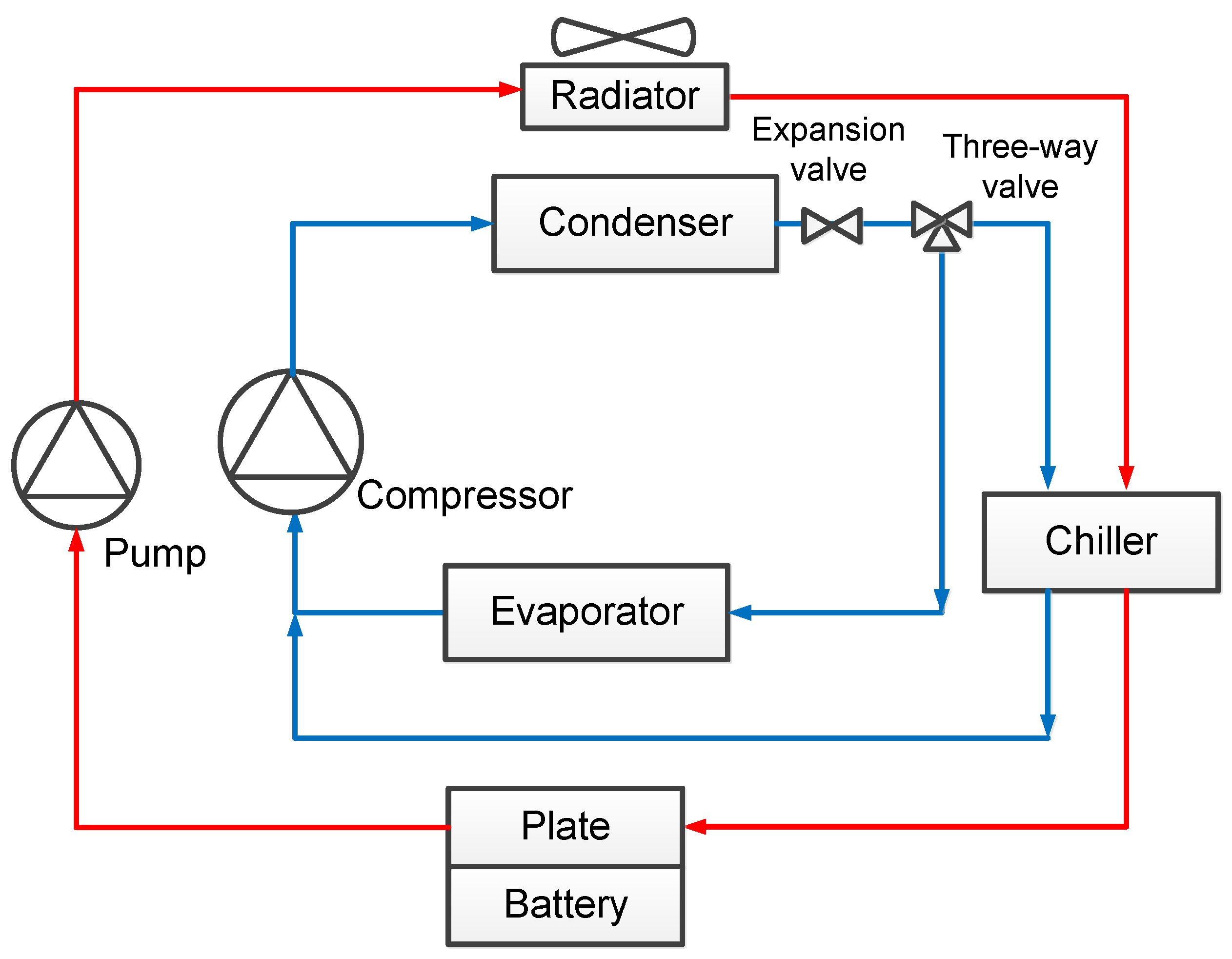
  • The radiator in the cooling water loop and chiller in the air-conditioning loop are connected in series rather than in parallel. Consequently, the cooling water first flows through the radiator to dissipate heat and then enters the chiller of the air-conditioning system. As a result, the cooling load (and hence the energy consumption) of the air-conditioning system is significantly reduced.
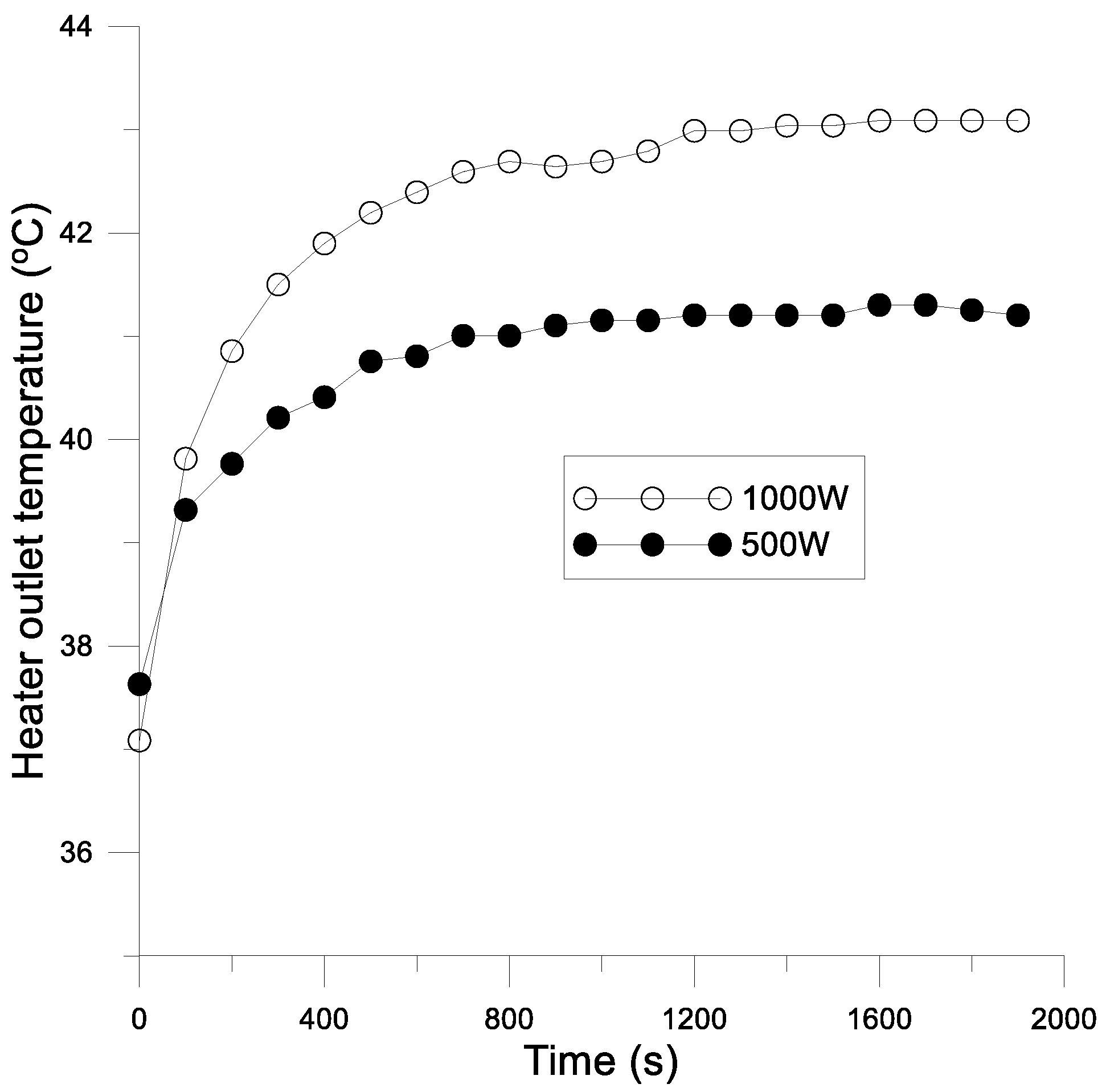
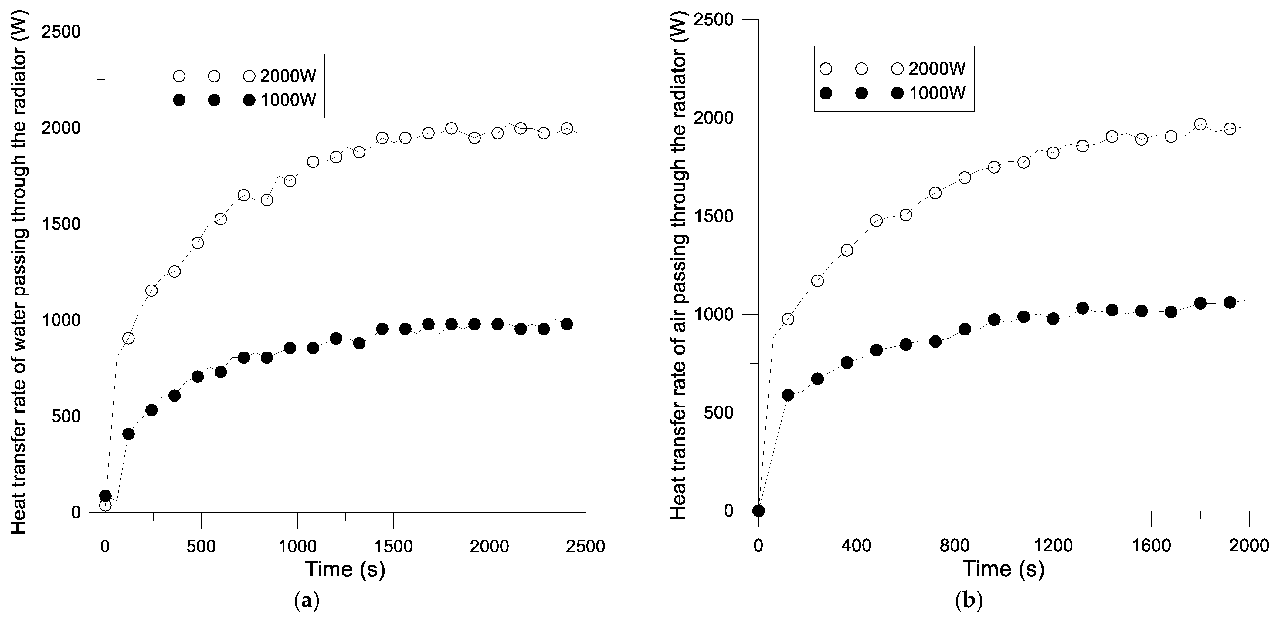
  • When the water temperature at the battery outlet side is assigned a maximum permissible value of 43 °C, the heat dissipation capacity of the proposed pre-cooling system is equal to 1000 W for an ambient temperature of 35 °C, 2000 W for a temperature of 30 °C, 3167 W for a temperature of 20 °C, and more than 4000 W for a temperature of 7 °C. For a heat generation rate of the battery lower than these maximum heat dissipation values, the pre-cooling system is sufficient to maintain the outlet water temperature of the battery at the target value of 43 °C. Hence, the air-conditioning system is not required, and the cooling load is correspondingly reduced.
  • In the winter (7 °C), the cooling fan of the radiator is not required and the heat energy dissipated by the battery can be used as the heat source for the air-conditioning system, thereby further reducing its energy consumption.

Author Contributions

T.-B.C. contributed to the conception and design of the experiments, analyzed the data, and wrote the paper; Y.-Z.X. and Y.-F.L. contributed to the investigation and performed the experiments. All authors have read and agreed to the published version of the manuscript.

Funding

This research was funded by the Ministry of Science and Technology (MOST) of Taiwan, grant numbers MOST 109-2221-E-415-006-MY2 and MOST 111-2221-E-415-008.

Institutional Review Board Statement

Not applicable.

Informed Consent Statement

Not applicable.

Data Availability Statement

Not applicable.

Conflicts of Interest

The authors declare no conflict of interest.

References

  1. Sato, N. Thermal behavior analysis of lithium-ion batteries for electric and hybrid vehicles. Power Sources 2001, 99, 70–77. [Google Scholar] [CrossRef]
  2. Dunn, B.; Kamath, H.; Tarascon, J.M. Electrical energy storage for the grid: A battery of choices. Science 2011, 334, 928–935. [Google Scholar] [CrossRef] [PubMed]
  3. Meiwes, H.B.; Drillkens, J.; Lunz, B.; Muennix, J.; Rothgang, S.; Kowal, J.; Sauer, D.U. A review of current automotive battery technology and future prospects. Automob. Eng. 2013, 227, 761–776. [Google Scholar] [CrossRef]
  4. Bukhari, S.M.A.S.; Maqsood, J.; Baig, M.Q.; Ashraf, S.; Khan, T.A. Comparison of Characteristics—Lead Acid, Nickel Based, Lead Crystal and Lithium Based Batteries. In Proceedings of the 2015 17th UKSim-AMSS International Conference on Modelling and Simulation (UKSim), Cambridge, UK, 25–27 March 2015. [Google Scholar]
  5. Tarascon, J.M.; Armand, M. Issues and challenges facing rechargeable lithium batteries. In Materials for Sustainable Energy: A Collection of Peer-Reviewed Research and Review Articles from Nature Publishing Group; Macmillan Publishers Ltd.: London, UK, 2011; pp. 171–179. [Google Scholar]
  6. Sasaki, T.; Ukyo, Y.; Novák, P. Memory effect in a lithium-ion battery. Nat. Mater. 2013, 12, 569. [Google Scholar] [CrossRef]
  7. Etacheri, V.; Marom, R.; Elazari, R.; Salitra, G.; Aurbach, D. Challenges in the development of advanced Li-ion batteries: A review. Energy Environ. Sci. 2011, 4, 3243–3262. [Google Scholar] [CrossRef]
  8. Bandhauer, T.M.; Garimella, S.; Fuller, T.F. A Critical Review of Thermal Issues in Lithium-Ion Batteries. J. Electrochem. Soc. 2011, 158, R1. [Google Scholar] [CrossRef]
  9. Pesaran, A.A. Battery thermal models for hybrid vehicle simulations. Power Sources 2002, 110, 377–382. [Google Scholar] [CrossRef]
  10. Pesaran, A.; Santhanagopalan, S.; Kim, G.H. Addressing the Impact of Temperature Extremes on Large Format Li-Ion Batteries for Vehicle Applications. In Proceedings of the 30th International Battery Seminar, Fort Lauderdale, FL, USA, 11–14 March 2013. [Google Scholar]
  11. Wang, T.; Tseng, K.J.; Zhao, J.; Wei, Z. Thermal investigation of lithium-ion battery module with different cell arrangement structures and forced air-cooling strategies. Appl. Energy 2014, 134, 229–238. [Google Scholar] [CrossRef]
  12. Rao, Z.; Wang, S. A review of power battery thermal energy management. Renew. Sustain. Energy Rev. 2011, 15, 4554–4571. [Google Scholar] [CrossRef]
  13. Wang, Q.; Jiang, B.; Li, B.; Yan, Y. A critical review of thermal management models and solutions of lithium-ion batteries for the development of pure electric vehicles. Renew. Sustain. Energy Rev. 2016, 64, 106–128. [Google Scholar] [CrossRef]
  14. Park, H. A design of air flow configuration for cooling lithium ion battery in hybrid electric vehicles. J. Power Sources 2013, 239, 30–36. [Google Scholar] [CrossRef]
  15. Chen, K.; Li, Z.; Chen, Y.; Long, S.; Hou, J.; Song, M.; Wang, S. Design of Parallel Air-Cooled Battery Thermal Management System through Numerical Study. Energies 2017, 10, 1677. [Google Scholar] [CrossRef]
  16. Jarrett, A.; Kim, I.Y. Design optimization of electric vehicle battery cooling plates for thermal performance. J. Power Sources 2011, 196, 10359–10368. [Google Scholar] [CrossRef]
  17. Jin, L.W.; Lee, P.S.; Kong, X.X.; Fan, Y.; Chou, S.K. Ultra-thin minichannel LCP for EV battery thermal management. Appl. Energy 2014, 113, 1786–1794. [Google Scholar] [CrossRef]
  18. Huo, Y.; Rao, Z.; Liu, X.; Zhao, J. Investigation of power battery thermal management by using mini-channel cold plate. Energy Convers. Manag. 2015, 89, 387–395. [Google Scholar] [CrossRef]
  19. Malik, M.; Dincer, I.; Rosen, M.A.; Mathew, M.; Fowler, M. Thermal and electrical performance evaluations of series connected Li-ion batteries in a pack with liquid cooling. Appl. Therm. Eng. 2018, 129, 472–481. [Google Scholar] [CrossRef]
  20. Kim, J.; Oh, J.; Lee, H. Review on battery thermal management system for electric vehicles. Appl. Therm. Eng. 2019, 149, 192–212. [Google Scholar] [CrossRef]
  21. Zou, H.; Jiang, B.; Wang, Q.; Tian, C.; Yan, Y. Performance analysis of a heat pump air conditioning system coupling with battery cooling for electric vehicles. Energy Procedia 2014, 61, 891–894. [Google Scholar] [CrossRef]
  22. Scrosati, B.; Garche, J.; Tillmetz, W. Advances in Battery Technologies for Electric Vehicles; Woodhead Publishing: Cambridge, UK, 2015. [Google Scholar]
  23. Krueger, I.; Limperich, D.; Schmitz, G. Energy Consumption of Battery Cooling in Hybrid Electric Vehicles. In Proceedings of the International Refrigeration and Air Conditioning Conference at Purdue, West Lafayette, IN, USA, 16–19 July 2012. [Google Scholar]
  24. Tian, Z.; Gan, W.; Zhang, X.; Gu, B.; Yang, L. Investigation on an integrated thermal management system with battery cooling and motor waste heat recovery for electric vehicle. Appl. Therm. Eng. 2018, 136, 16–27. [Google Scholar] [CrossRef]
  25. Cen, J.; Jiang, F. Li-ion power battery temperature control by a battery thermal management and vehicle cabin air conditioning integrated system. Energy Sustain. Dev. 2020, 57, 141–148. [Google Scholar] [CrossRef]
  26. CNS 14464; Non-Ducted Air Conditioners and Heat Pumps—Testing and Rating for Performance. Taiwan National Standard: Taipei City, Taiwan, 2020. Available online: http://cns-standards.org/CNS_standard_cn.asp?CODE=CNS%2014464 (accessed on 13 June 2021).
  27. Taiwan Central Weather Bureau. Monthly Mean Temperature. 2020. Available online: https://www.cwb.gov.tw/V8/E/C/Statistics/monthlymean.html (accessed on 13 June 2021).
  28. JIS C 9220; Household Heat Pump Water Heater. Japanese Industrial Standards: Tokyo, Japan, 2018. Available online: https://www.catalabo.org/iportal/CatalogDownload.do?method=downloadPdfCatalogPage&type=downloadPdfCatalogPage&volumeID=CATALABO&categoryID=&catalogID=&catalogCategoryID=&pageGroupID=&pageID=57667940000 (accessed on 1 June 2023).
  29. Holman, J.P. Experimental Methods for Engineers; McGraw-Hill: New York, NY, USA, 1994. [Google Scholar]
  30. Chang, T.-B.; Sheu, J.-J.; Huang, J.-W. High-Efficiency HVAC System with Defog/Dehumidification Function for Electric Vehicles. Energies 2021, 14, 46. [Google Scholar] [CrossRef]
Figure 1. Model of proposed secondary-loop liquid cooling system for battery pre-cooling.
Sustainability 15 13182 g001
Figure 2. Schematic illustration of experimental pre-cooling system.
Sustainability 15 13182 g002
Figure 3. Photograph of experimental pre-cooling system.
Sustainability 15 13182 g003
Figure 4. Fin-and-tube heat exchanger (radiator).
Sustainability 15 13182 g004
Figure 5. DC cooling fan installation.
Sustainability 15 13182 g005
Figure 6. Heat dissipation of radiator under environmental temperature of 35 °C and different heating conditions: (a) cooling water side; (b) air side.
Sustainability 15 13182 g006
Figure 7. Temperature of cooling water on outlet side of heater under different heating conditions and environmental temperature of 35 °C.
Sustainability 15 13182 g007
Figure 8. Heat dissipation of radiator under environmental temperature of 30 °C and different heating conditions: (a) cooling water side; (b) air side.
Sustainability 15 13182 g008
Figure 9. Temperature of cooling water on outlet side of heater under different heating conditions and environmental temperature of 30 °C.
Sustainability 15 13182 g009
Figure 10. Heat dissipation of radiator under environmental temperature of 20 °C and different heating conditions: (a) cooling water side; (b) air side.
Sustainability 15 13182 g010
Figure 11. Temperature of cooling water on outlet side of heater under different heating conditions and environmental temperature of 20 °C.
Sustainability 15 13182 g011
Figure 12. Heat dissipation of radiator under environmental temperature of 7 °C and different heating conditions: (a) cooling water side; (b) air side.
Sustainability 15 13182 g012
Figure 13. Temperature of cooling water on outlet side of heater under different heating conditions and environmental temperature of 7 °C.
Sustainability 15 13182 g013
Table 1. Specification of cooling fan.
Current (A)Voltage (DC V)Fan Diameter (mm)Average Wind Speed (km/h)Maximum Volume Flow Rate (m3/h)
7.81232010820
Table 2. Specification of electric water heater.
ModelCurrent
(A)
Voltage
(V)
Power
(kW)
Weight
(kg)
Length
(mm)
Width
(mm)
Height
(mm)
NC5-LB402208.82.6314240137
Table 3. Specification of temperature and humidity test chamber.
Length
(m)
Width
(m)
Height
(m)
Temperature Range (°C)Temperature Accuracy (°C)Humidity Range
(%)
Humidity Accuracy (%)
2.21.82.130~50±0.310~90±2.5
Table 4. Experimental temperature settings and related test specifications.
Summer (35 °C)Summer (30 °C)Spring and Fall (20 °C)Winter (7 °C)
Dry bulb temperature35 °C30 °C20 °C7 °C
Wet bulb temperature24 °C27 °C17.7 °C6 °C
SpecificationCNS14464, T1Weather data from Taiwan Central Weather BureauWeather data from Taiwan Central Weather BureauJIS C 9920
Table 5. Accuracy of measuring components.
No.ApparatusMeasurement ParametersAccuracy
1ThermocoupleTemperature±0.2 °C
2Ultrasonic flowmeterMass flow rate of cooling water±1%
3Air capture hoodVolume flow rate of air±3%
Table 6. Energy-saving effect of the proposed battery pre-cooling system in different climates.
ClimateAmbient TemperatureHeat Dissipation Capacity
(Reduced Cooling Load for A/C System)
Energy Saving of
A/C System
High summer35 °C1000 W400 W
Mean summer30 °C2000 W800 W
Spring and fall20 °C3167 W1267 W
Winter7 °C4485 W1794 W
Disclaimer/Publisher’s Note: The statements, opinions and data contained in all publications are solely those of the individual author(s) and contributor(s) and not of MDPI and/or the editor(s). MDPI and/or the editor(s) disclaim responsibility for any injury to people or property resulting from any ideas, methods, instructions or products referred to in the content.

