Technical Note

Evaluation of the Performance of the Horizontal Drain in Drainage of the Infiltrated Water from Slope Soil under Rainfall Conditions

1
College of Information Engineering, Xizang Minzu University, Xianyang 712082, China
2
Key Laboratory of Concrete and Prestressed Concrete Structures of Ministry of Education, Southeast University, Nanjing 210096, China
3
Department of Civil and Environmental Engineering, School of Engineering and Digital Sciences, Nazarbayev University, Kabanbay Batyr Ave., 53, Nur-Sultan 010000, Kazakhstan
4
Hocklim Engineering Pte Ltd., Singapore 659530, Singapore
*
Author to whom correspondence should be addressed.
Sustainability 2023, 15(19), 14163; https://doi.org/10.3390/su151914163
Submission received: 17 August 2023 / Revised: 12 September 2023 / Accepted: 20 September 2023 / Published: 25 September 2023
(This article belongs to the Section Environmental Sustainability and Applications)

Abstract

:
It is known that rainwater infiltration is crucial for rainfall-induced slope failure because the infiltrated water can significantly weaken the shear strength of unsaturated soil. Horizontal drains are commonly used to provide appropriate drainage for the rainwater that percolates out of a slope. However, the effects of the length and location of the subsoil pipe on the performance of horizontal drains have not been extensively investigated. In this paper, a parametric analysis by using a numerical model was adopted to investigate the distribution of pore-water pressure in a slope. The results reveal that an inclination angle of 10–15 degrees and strategic placement at the slope toe and mid-slope provide optimal drainage performance, as compared to the effect of pipe length. Multi-layers of horizontal drain (based on 10 m length) are recommended for slopes with a height of more than 15 m.

1. Introduction

Slope stability remains a critical concern in geotechnical engineering, especially in areas susceptible to heavy or inconsistent rainfall [1,2,3,4]. The effects of rainfall on slope stability have gained increasing attention from geotechnical engineers. Rainfall-induced slope instability is a complex process, driven by a multitude of factors that can ultimately lead to landslides [5]. These landslides, often sudden and unpredictable, pose a significant threat to human life and infrastructure [6,7]. The geotechnical mechanisms driving this process primarily relate to the increase in pore-water pressure within the slope due to rainfall infiltration [8,9]. The increase in pore-water pressure weakens the shear strength of unsaturated soil, potentially leading to slope failure [10]. The severity and unpredictability of these events underscore the importance of understanding the mechanisms of rainfall-induced slope instability and developing effective measures to mitigate the associated risks.
To prevent slope failure under rainfall conditions, engineers employ various methods including the use of horizontal drains, slope reinforcement techniques, soil hardening measures, surface water management techniques, groundwater control methods, and proper vegetation management [11,12,13]. Among the various methods, the use of horizontal drains has shown considerable promise both technically and economically. Horizontal drains are essentially holes drilled into an embankment or cut slope, lined with a perforated metal or slotted plastic casing [14]. These drains serve a crucial function in managing subsurface water, which is one of the key factors in the instability of slopes under rainfall conditions. By reducing excess pore-water pressure and lowering the normal water table, horizontal drains can significantly enhance the stability of slopes [15].
The use of horizontal drains in both preconstruction and postconstruction applications on Interstate 70 in the Vail area of west–central Colorado is cost-effective in preventing and correcting failures in cut-and-fill slopes [14]. However, the use of horizontal drains is limited to specific locations where subsurface mapping and sampling indicate that groundwater is a major detrimental factor and can be effectively collected for a required time period.
Several studies have evaluated the effectiveness of horizontal drains in slope stability and groundwater control. Cai et al. [16] used a three-dimensional finite element analysis to show that horizontal drains can effectively manage groundwater levels and enhance slope stability during rainfall, but their effectiveness decreases when extended beyond a certain length. Rahardjo et al. [15] suggested that installing a few strategically placed drains could be more effective than uniformly spacing many drains across the slope. Using the elasto-visco-plastic Finite Element Method (FEM), Nagahara et al. [17] simulated the behavior of a fill with horizontal drains to facilitate a rational design. Rahardjo et al. [18] and Argunhan-Atalay et al. [19] highlighted the importance of horizontal drains in maintaining negative pore-water pressure and managing excess pore-water pressure, respectively, by using SEEP/W software. Lakruwan et al. [20] experimentally evaluated how different perforation arrangements of horizontal drains impact their hydraulic performance for landslide mitigation, finding that circular holes distributed over more of the pipe length result in the highest performance.
The effectiveness of horizontal drains has been refined and improved since their introduction by the California Division of Highways in 1939. Developments such as the polyvinyl chloride pipe, improvements in drill bits and drill stems, and the advent of drilling machines capable of producing high thrust and torque have made subsurface drainage a significant and economical alternative in the repair and prevention of certain types of landslides [14]. While horizontal drains have proven effective for slope stabilization, the current design process relies heavily on trial and error rather than systematic optimization using quantitative methods and research-based design guidelines [21]. Still, there is a lack of comprehensive research on the optimization of horizontal drain design under constant rainfall conditions. Additionally, the current literature does not offer a clear consensus on the critical length of horizontal drains, beyond which the rate of increase in the safety factor becomes smaller.
The effects of the length, inclination, and position of the horizontal drain on the performance of drainage of infiltrated water in slope soil has not been extensively investigated. On this note, a parametric study using numerical analyses is adopted to evaluate those effects on the performance of a horizontal drain in a slope under rainfall conditions.

2. Design of Horizontal Drain

The design of a horizontal drain involves several considerations [22]. Comprehensive site characterization is essential to horizontal drain design. Field investigations should aim to develop a geotechnical model identifying potential failure modes and locating aquifers contributing to instability [23]. Important information includes slope geometry, geology, groundwater conditions, and soil/rock properties. Particularly significant is the presence of confined aquifers, their orientation and properties, and their hydraulic connectivity to recharge sources. Identifying seepage paths and quantifying groundwater flows allows appropriate drain layouts to be developed.
The length of a horizontal drain is a crucial factor in its effectiveness. The primary function of a horizontal drain is to provide a pathway for water to escape from the slope. As such, the drain must be long enough to reach areas of high pore-water pressure. However, increasing the length of the drain beyond a certain point may not significantly enhance its effectiveness. Therefore, the optimal length of a horizontal drain is largely dependent on the specific characteristics of the slope, including its width and the distribution of pore-water pressure [24].
The orientation of a horizontal drain refers to the angle at which it intersects the aquifer. Ideally, the drain should intersect the aquifer at a small angle and pass completely through it. This maximizes the interface area between the drain and the aquifer, thereby enhancing the drain’s effectiveness [25].
The diameter of a horizontal drain is another important factor in its design. A larger diameter allows for a greater volume of water to be drained, thereby potentially enhancing the drain’s effectiveness. However, a larger diameter also requires a larger drill hole, which can increase the risk of slope instability during the installation process. Therefore, the optimal diameter of a horizontal drain is a balance between maximizing drainage capacity and minimizing the risk of slope instability.
Horizontal drains play an important role in stabilizing failures driven by elevated groundwater pressures. Careful layout, sizing, orientation, drilling, and filter pack design are required for satisfactory performance. Significant aquifer heterogeneity poses difficulties for design. Installation should remain flexible to adjust to observed conditions. With proper site characterization and integration with other stabilization measures, horizontal drains can improve the reliability and safety of unstable slopes.

3. Numerical Modeling

3.1. Model Assumptions

Numerical analyses have been used for the evaluation of water infiltration in slope soil [26,27,28]. The numerical model of horizontal drains using GeoStudio Seep/W 2018 R2 is based on several key assumptions, such as geometrical, hydraulic, and material assumptions [29].
Geometrical Assumptions: In two-dimensional analysis, the horizontal drain is represented as a line. It is assumed that the drain extends to the boundary of the model at both ends, thereby capturing the full extent of its influence on the seepage.
Hydraulic Assumptions: The functionality of the drain is modeled on the assumption that it reduces the pore-water pressure to a specific value. In the context of an unconfined aquifer, this pressure is assumed to be equivalent to atmospheric pressure. This assumption allows the model to reflect the drain’s role in mitigating the impact of pore-water pressure on slope stability.
Material Assumptions: The material surrounding the horizontal drain is assumed to be homogenous and isotropic. This implies that its hydraulic properties, such as permeability, are uniform in all directions. While this assumption may not fully capture the complexity of real-world soil conditions, it provides a simplified framework for understanding the basic mechanics of how a horizontal drain interacts with the surrounding soil.

3.2. Geometry and Boundary Conditions

This study utilizes a numerical model with specific dimensions and characteristics to investigate the effectiveness of horizontal drains in slope stability under varying rainfall conditions. The total length of the model is 6.5 Hs, and the height is 3 Hs (Hs = 10 m). The model features a slope with a height of 1 Hs, maintaining a ratio of vertical to horizontal length of 2:1, which is a common slope gradient in many natural and man-made slopes.
The initial condition of the model includes a horizontal water table set at a depth of 1 Hs from the surface, as depicted in Figure 1. This initial water table level serves as the baseline for the analysis, allowing us to evaluate how different rainfall conditions and the use of horizontal drains affect the water table level and, consequently, the stability of the slope.
The boundary conditions of the model are set to reflect the real-world conditions under which slopes and horizontal drains operate. These conditions are divided into two main categories:
(a)
Surface Boundary: The surface boundary includes the slope surface, which is designated as the rainfall boundary. This is where precipitation will pervade the soil, simulating the natural process of rainfall infiltration.
(b)
Rest of the Boundary: The remaining boundaries, specifically the bottom and the side of the model, are set to impermeable conditions. This means that water cannot permeate through these boundaries.
The setting of a horizontal drain within the model includes two no-flow boundaries and a zero-pressure boundary. The no-flow boundaries ensure that water cannot flow through the surface of the drain, while the zero-pressure boundary facilitates the drainage of water. This setup is designed to closely replicate the functioning of actual horizontal drains in managing subsurface water in slopes.

3.3. Constitutive Models and Material Properties

Modeling the unsaturated properties of soil in GeoStudio Seep/W involves defining the Soil–Water Characteristic Curve (SWCC) and the hydraulic conductivity function. In the process of conducting a numerical simulation of unsaturated soil slopes, it is crucial to clearly define the unsaturated parameters and soil strength parameters of the unsaturated soil. These parameters have a direct impact on the accuracy and reliability of the simulation model.
In this study, the parameters for the Seep/W model were carefully selected based on empirical data. The data used for setting these parameters were derived from previous research on slope stability analysis [30], ensuring the preciseness of the data. Parameters were selected to align with real-world data, considering that a significant portion of the world’s terrain consists of residual soil. This ensures that the model is representative of the actual conditions found in many regions globally.
A key aspect of the parameter setting was the definition of the Soil–Water Characteristic Curve (SWCC). The SWCC describes the relationship between soil suction (or matric potential) and water content, and is crucial for modeling unsaturated soil [31]. In this study, the SWCC was defined using the fitting equation developed by Fredlund and Xing [32]. This equation is widely used in geotechnical engineering due to its ability to accurately represent a wide range of soil types and conditions. The equation is as follows:
θ = C ( ψ ) θ s ln e + ψ a n m = 1 ln 1 + ψ C r ln 1 + 10 6 C r θ s ln e + ψ a n m
where a ,   n ,   m are the fitting parameters; C r is the input value for the rough estimation of residual suction (kPa); and θ s is the saturated volumetric water content (%). The hydraulic conductivity function was another important part of the input information required for the analysis. In this study, the hydraulic conductivity function was estimated from SWCC using Zhai and Rahardjo’s [31] equation, illustrated as follows:
k ψ x = k ψ r e f i = x N   S ψ x S ψ i 2 S ψ x S ψ i + 1 2 ψ i 2 i = r e f N   S ψ r e f S ψ i 2 S ψ r e f S ψ i + 1 2 ψ i 2
where k ( ψ x ) is the estimated hydraulic conductivity at the suction of ψ x ; k ( ψ r e f ) is the hydraulic conductivity when the suction reaches the reference point; S ( ψ r e f ) is the degree of saturation with regard to the reference point; S ( ψ x ) and S ( ψ i ) are the degree of saturation corresponding to the soil suctions of ψ x and ψ i ; and N is the number of pore size classes.
Table 1 illustrates the fitting parameters and the saturated hydraulic conductivity of the residual soil. Those parameters are adopted as the input information for the seepage analysis in this study.

3.4. Numerical Simulation Scenarios

To represent the physical domain of the problem, a two-dimensional model was created, based on the actual measurements of the slope under study. The model was discretized using a mesh of triangular elements. A higher element density (finer mesh) was employed in regions close to the horizontal drain to capture the localized effects of the drain with greater accuracy.
The simulation also included a transient analysis to study time-dependent behavior under constant rainfall. This analysis was performed with a time increment of one hour, which refers to the interval at which the model calculations are updated. The one-hour increment was chosen to balance computational efficiency with the accuracy needed to capture rapid changes in soil–water interactions [29]. The transient analysis provided valuable insights into the dynamic behavior of soil–water interactions and the time-dependent effectiveness of the horizontal drains.
The simulation scenarios comprised three primary research strategies, each designed to explore the influence of a specific factor on the drainage effectiveness of horizontal drains. The factors under investigation included drain length, drain inclination angle, and drain placement position. For all simulations, the rainfall conditions were kept constant, with a daily rainfall of 30 mm sustained over a period of six days, followed by four days with no rainfall. This specific rainfall setting was chosen to ensure that the entire slope became saturated, which is crucial for the analysis as it allows the effectiveness of different horizontal drain setting scenarios to be compared.
This numerical simulation study was structured around three primary research plans. Each of these plans was designed to investigate how a specific factor influences the drainage effectiveness of horizontal drains. Throughout these plans, the rainfall conditions remained constant, with a daily rainfall of 30 mm sustained over a period of 6 days. Details of the research strategies are given in Table 2.
(a)
Impact of Drain Length: This plan varies the length of the horizontal drain to analyze its effect on drainage. Drain lengths of 4 m, 7 m, 10 m, and 15 m were examined.
(b)
Impact of Drain Inclination Angle: This plan alters the inclination angle of the horizontal drain to assess its influence on drainage. Drain inclination angles of 5°, 10°, and 15° were considered.
(c)
Impact of Drain Placement Position: This plan modifies the placement position of the horizontal drain to evaluate its impact on drainage. Drain positions in the middle and lower parts of the slope were tested.

4. Results and Discussions

4.1. Selection of the Sections for the Monitoring of the Distribution of Pore-Water Pressure

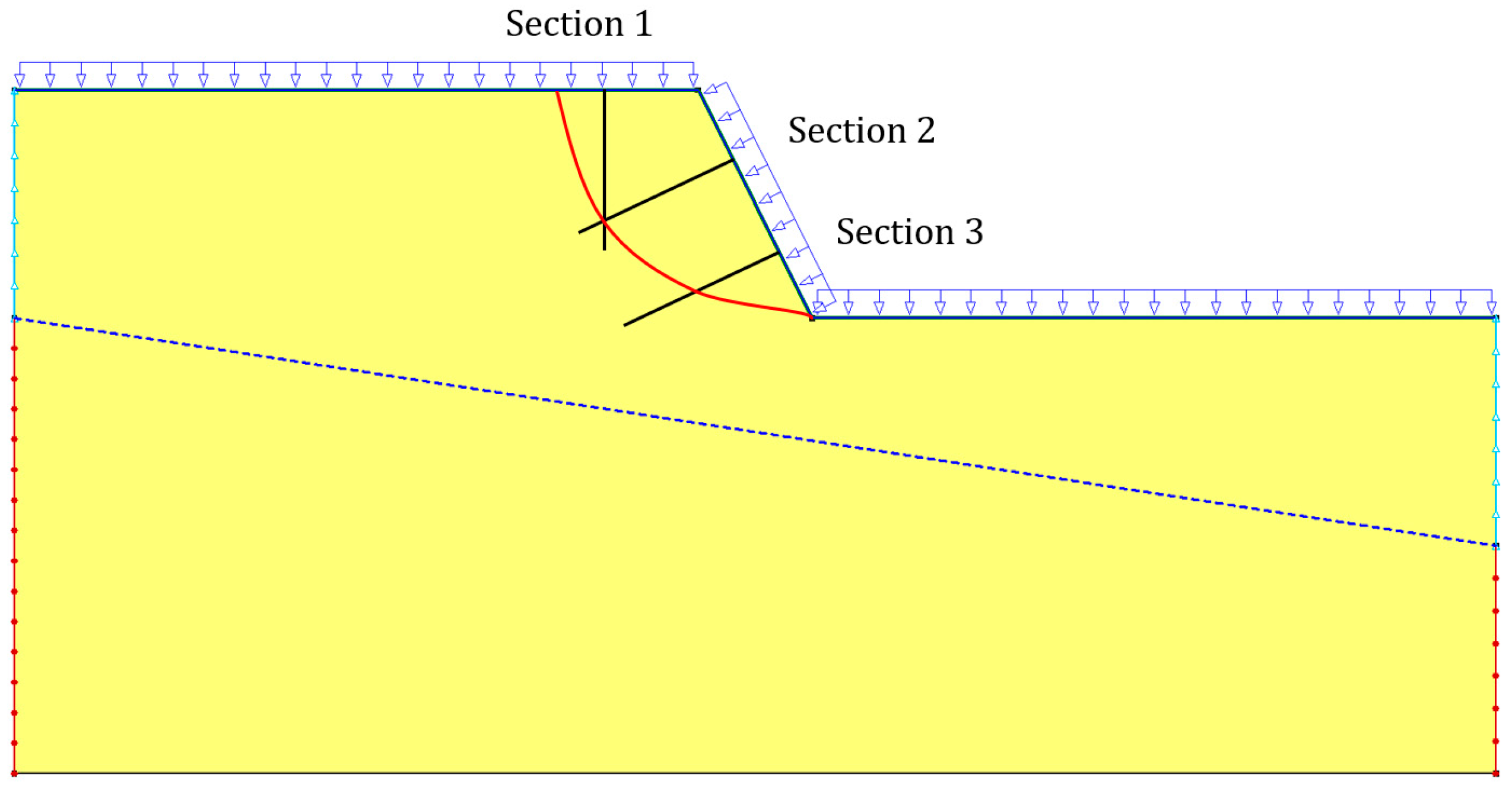
By examining the pore-water pressure across these three sections, this study aimed to derive a holistic view of the slope’s seepage behavior as illustrated in Figure 2. Section 1 is strategically positioned at the top of the slope. This location is pivotal as it captures the initial interaction of rainfall with the slope, offering insights into the onset of water infiltration and its immediate effects on pore-water pressure. The subsequent sections, Sections 2 and 3, are oriented perpendicular to the slope. These sections are spaced 5 m apart, providing a layered perspective of the slope’s interior.

4.2. The Distribution of the Pore-Water Pressure under Rainfall Conditions

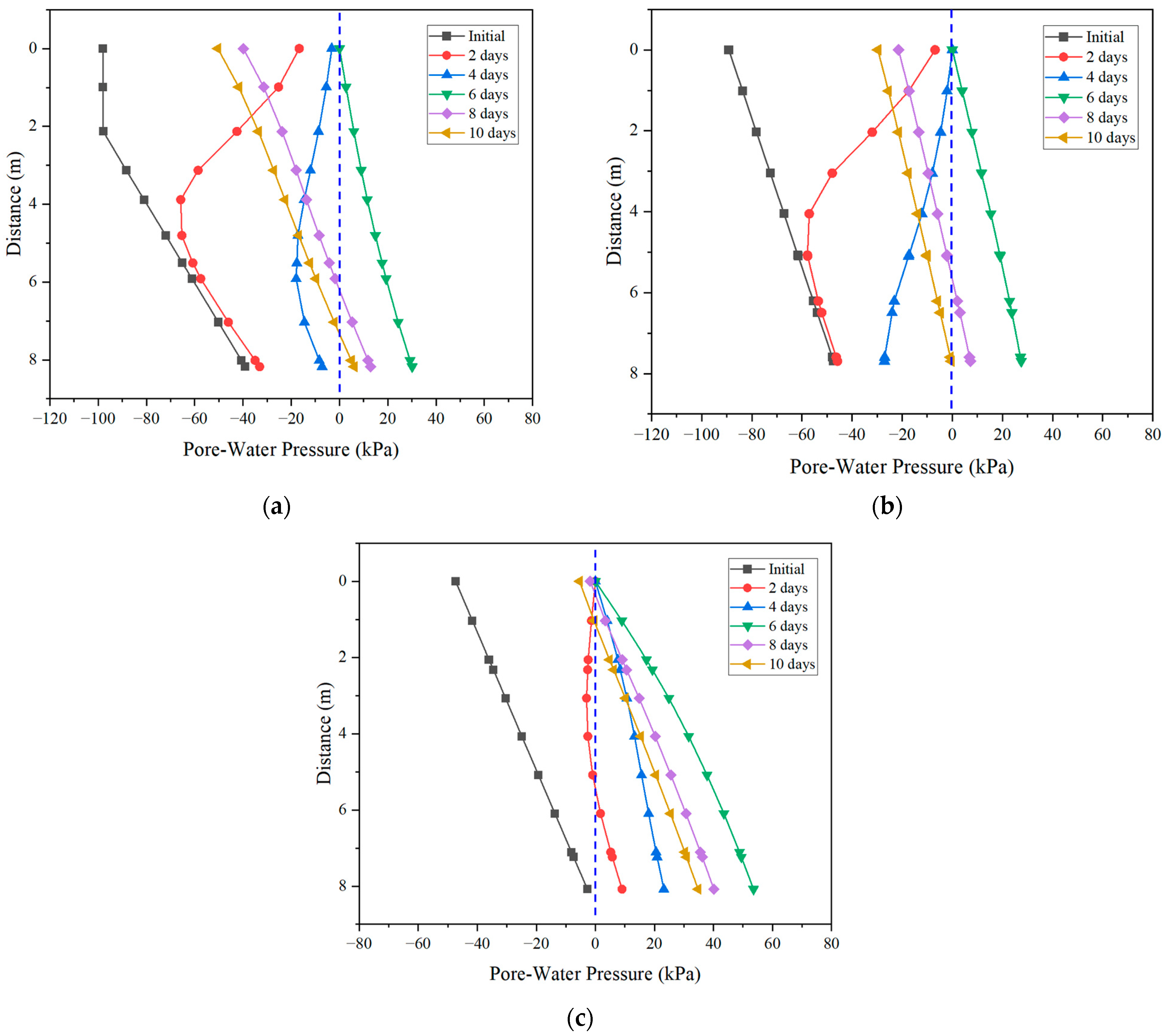
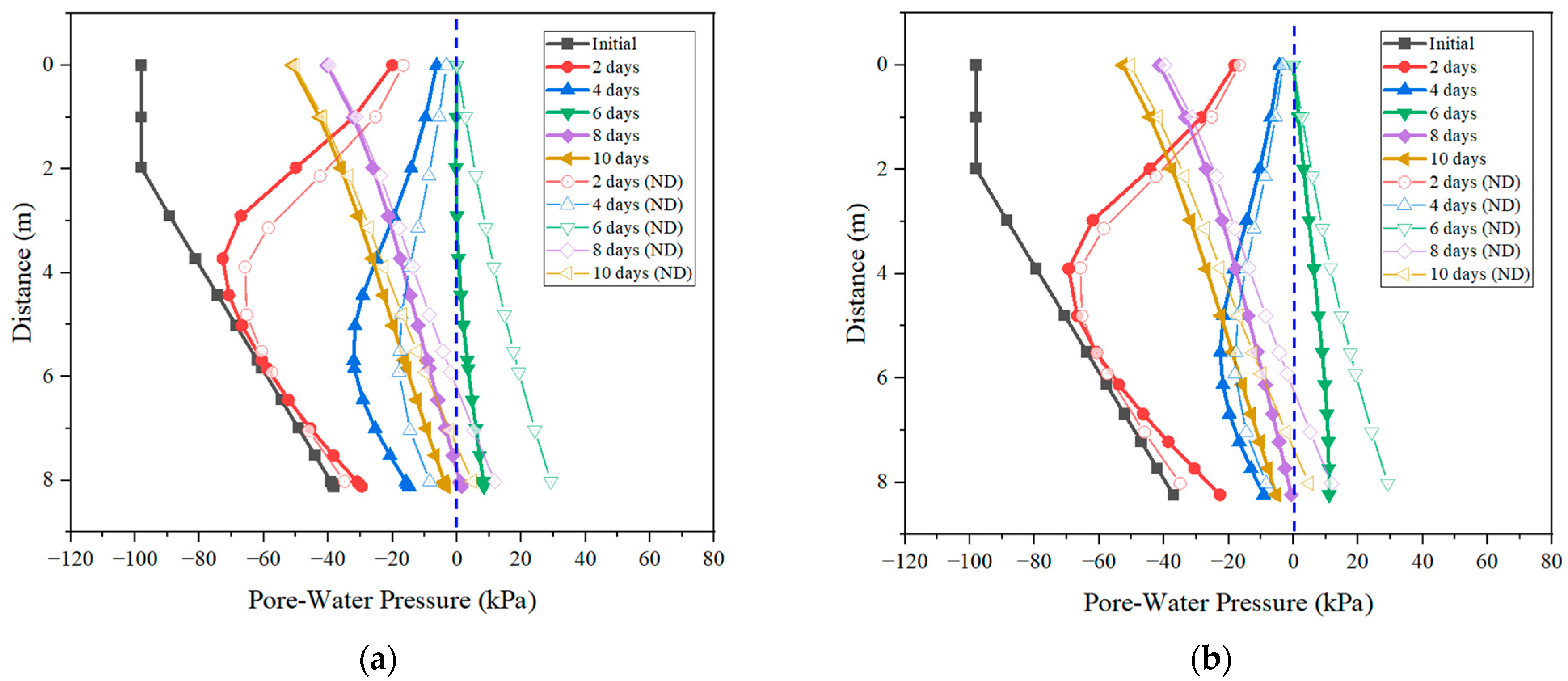
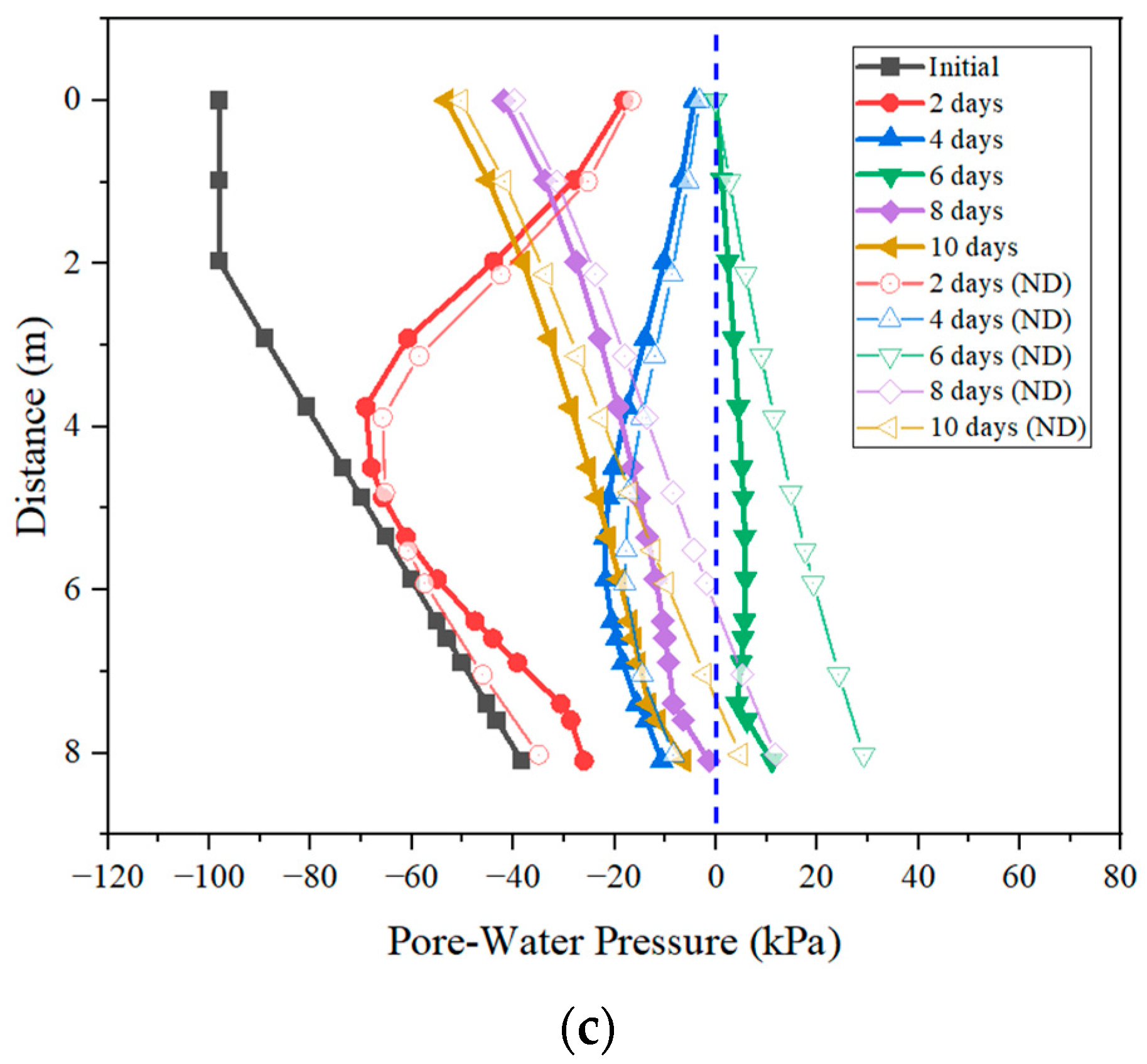
Figure 3 illustrates the distribution of the pore-water pressure on three distinct sections of the slope. Zero pore-water pressure serves as an indicator of the groundwater table (G.W.T) within the slope.
It was observed that the soil was fully saturated after 6 days of continuous rainfall, and when the rainfall stopped on the 7th day the water discharged from the slope soil as shown on all three sections. However, the speed of the discharge was the highest near the crest (shown on Section 1), followed by the middle of the slope (shown on Section 2), and the lowest near the toe (shown on Section 3).

4.3. Effect of the Pipe Length on the Performance of Discharging the Infiltrated Water

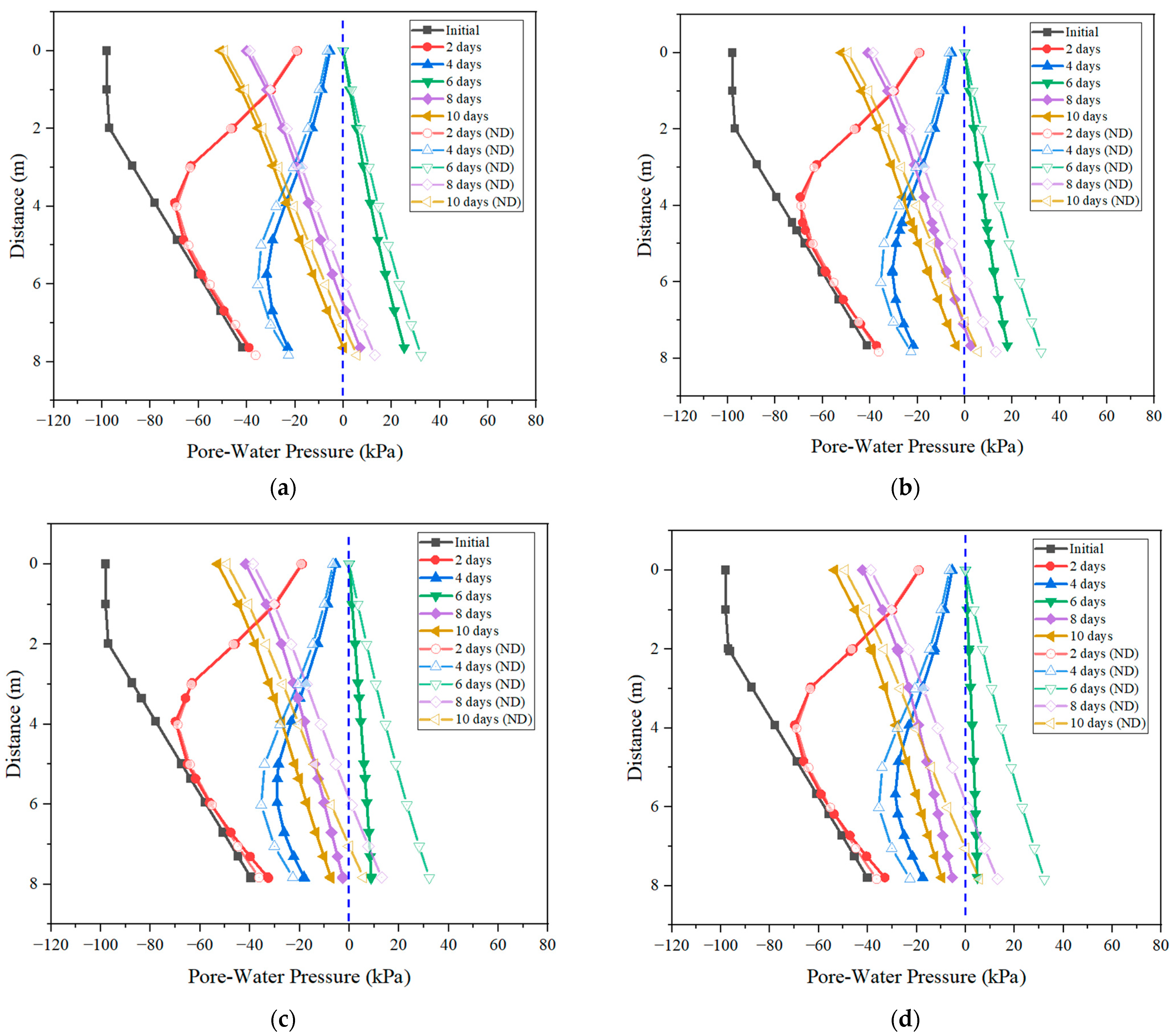
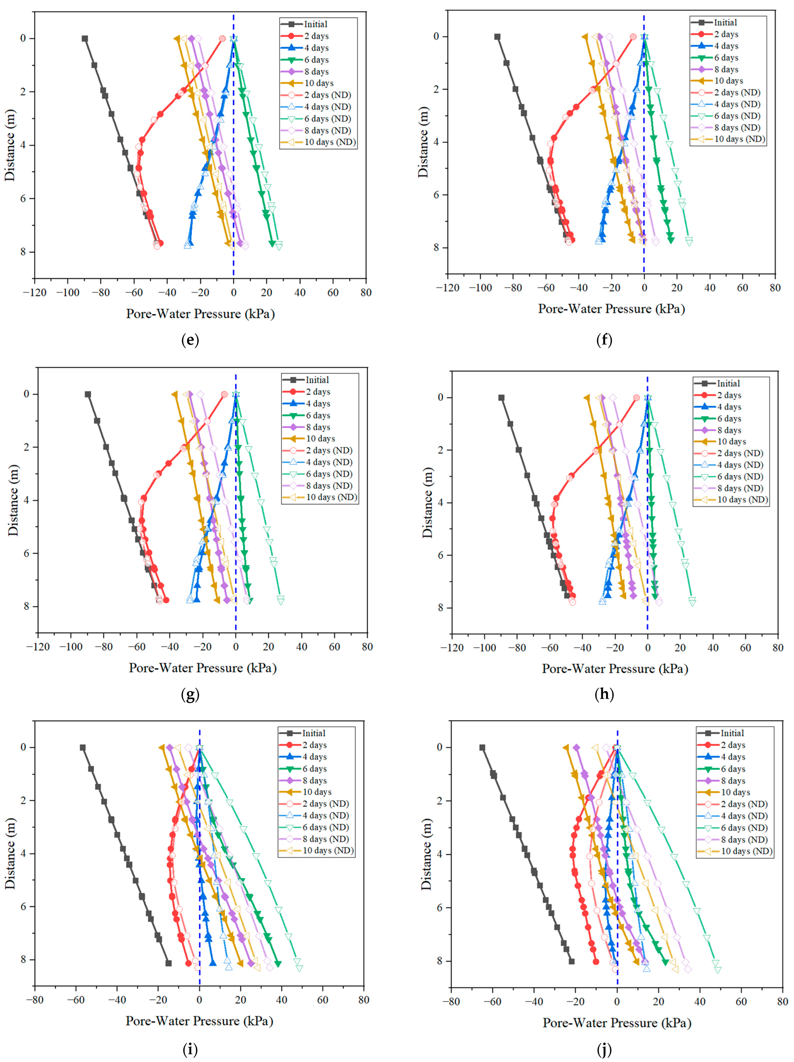
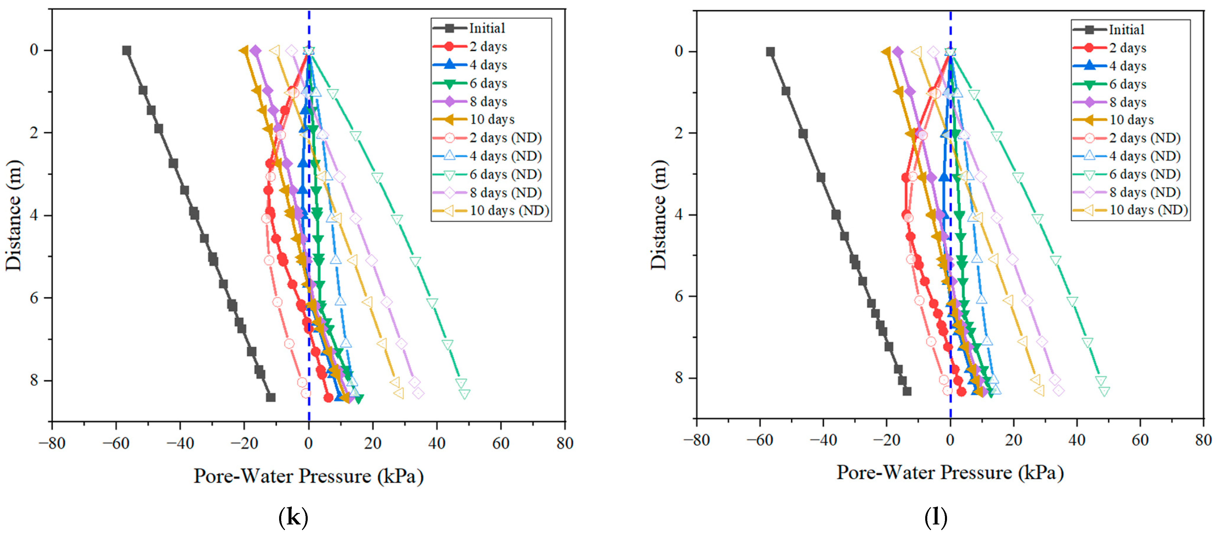
Figure 4 illustrates the distribution of the pore-water pressure from the different scenarios by considering different lengths of the horizontal drain. For comparison, the distributions of pore-water pressure in the slope for the scenario without the drainage pipe were also adopted and are shown in Figure 4.
As shown in Figure 4, the horizontal drain is helpful for discharging the infiltrated water (i.e., reducing the pore-water pressure). Drains with lengths of 4 m and 7 m exhibit noticeable limitations, with their drainage efficiency being inferior to the 10 m drain (Figure 4a,b,e,f,i,j). However, it seems the performance of the 10 m long pipe is similar to that of the 13 m long pipe, suggesting limited benefits from extending the drain beyond 10 m in these contexts (Figure 4c,d,g,h,k,l). As suggested, the recommended length of the horizontal drain is 1 Hs.

4.4. Effect of the Pipe Inclination on the Performance of Discharging the Infiltrated Water

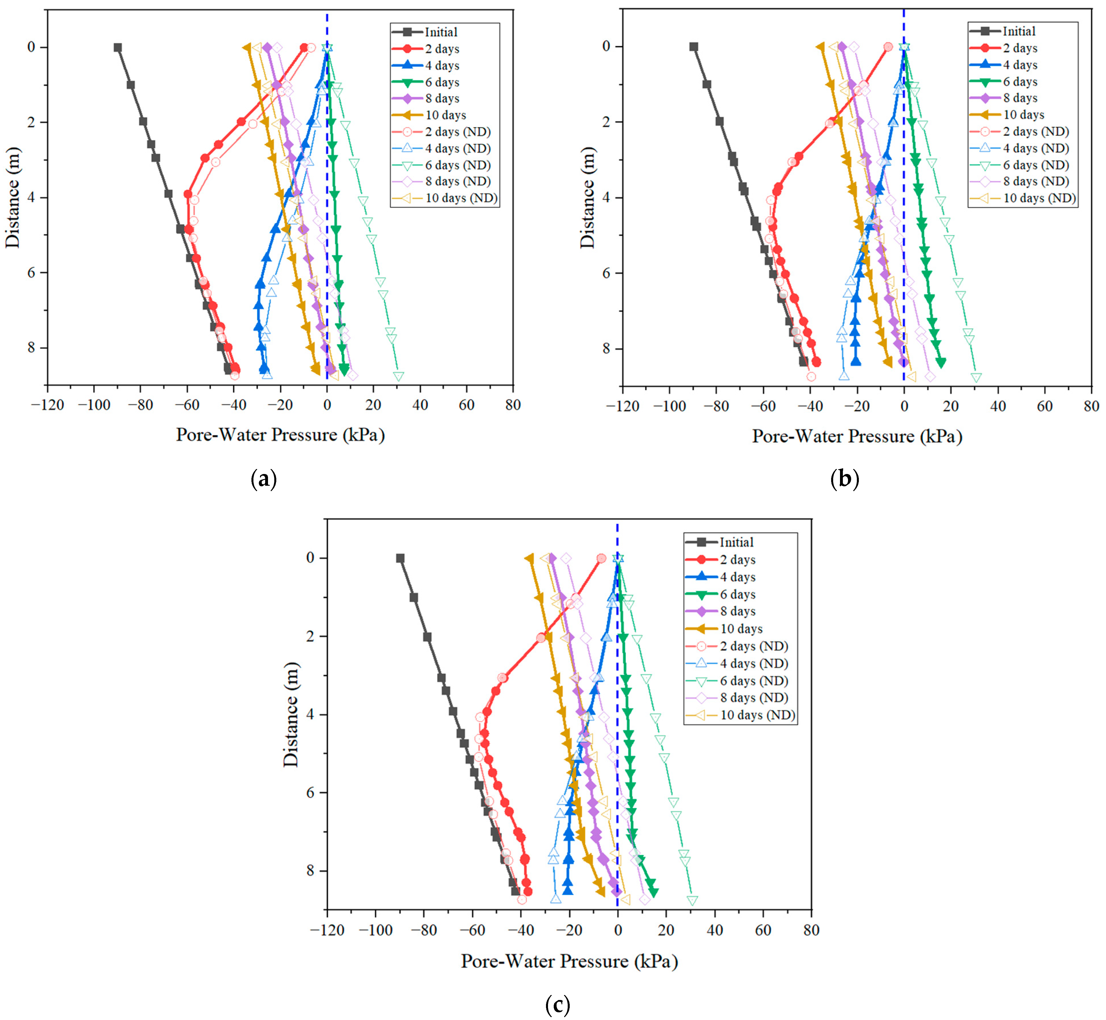
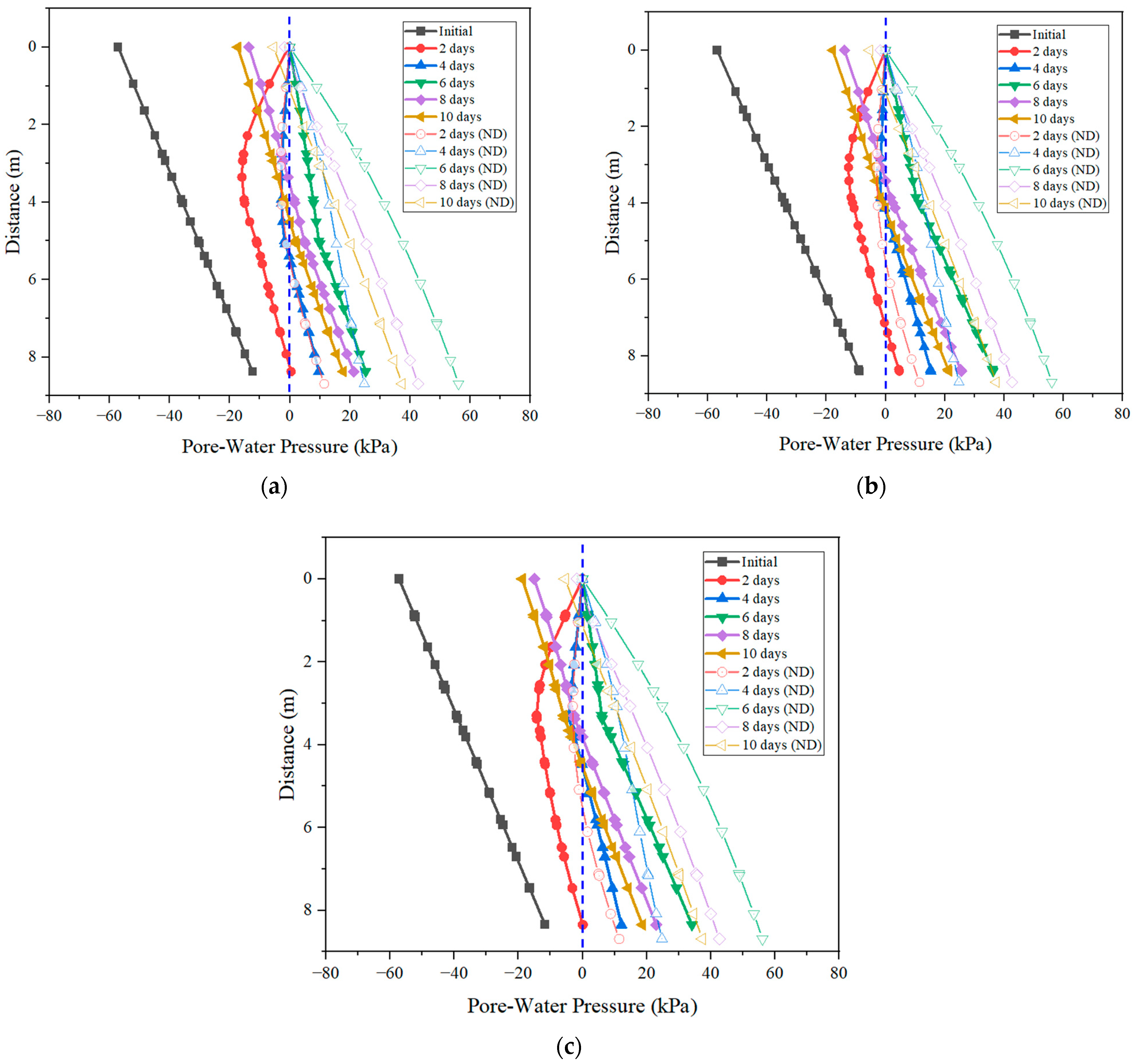
Figure 5, Figure 6 and Figure 7 shows the distribution of pore-water pressure on Sections 1–3, respectively, with different pipe inclinations.
Figure 5, Figure 6 and Figure 7 indicate that the effect of the pipe inclination on the performance of the discharging of the infiltrated soil in the slope is insignificant, as observed from the analyzed results for the three sections. It is noted that a higher inclination results in more difficulty in site construction. As a result, 5~10° is recommended for the installation of the horizontal drain.

4.5. Effect of the Position of the Pipe on the Performance of Discharging the Infiltrated Water

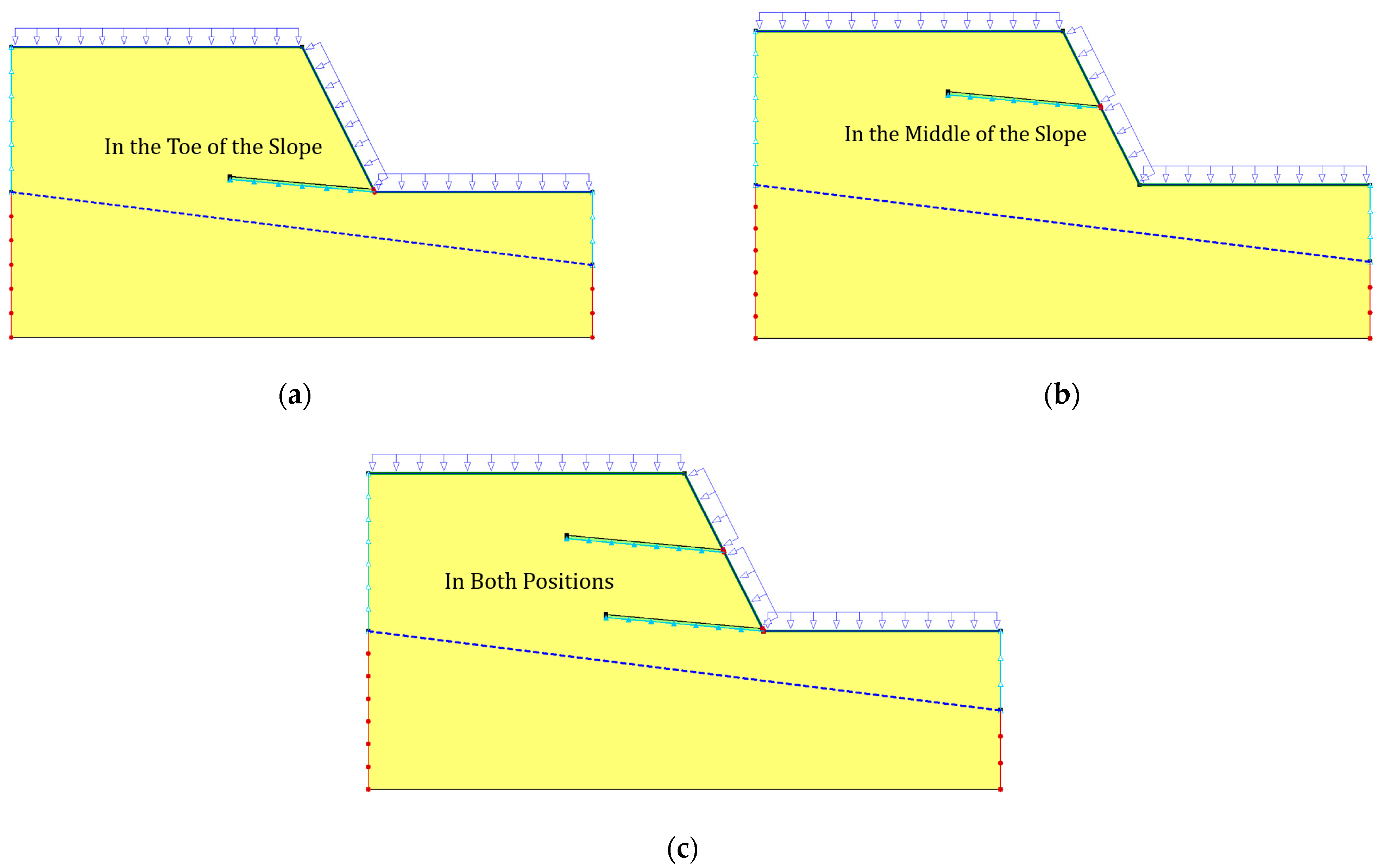
Figure 8 illustrates three distinct placement strategies for the horizontal drain within the slope. The strategies are depicted in Figure 8a–c, where a horizontal drain is positioned near the toe of the slope, in the middle of the slope, and in both locations, respectively.
It is noteworthy that the first placement strategy, as depicted in Figure 8a, aligns precisely with the inclination angle of 5°. The pore-water pressure distribution corresponding to this specific placement across the three sections can be seen in Figure 5a, Figure 6a and Figure 7a.
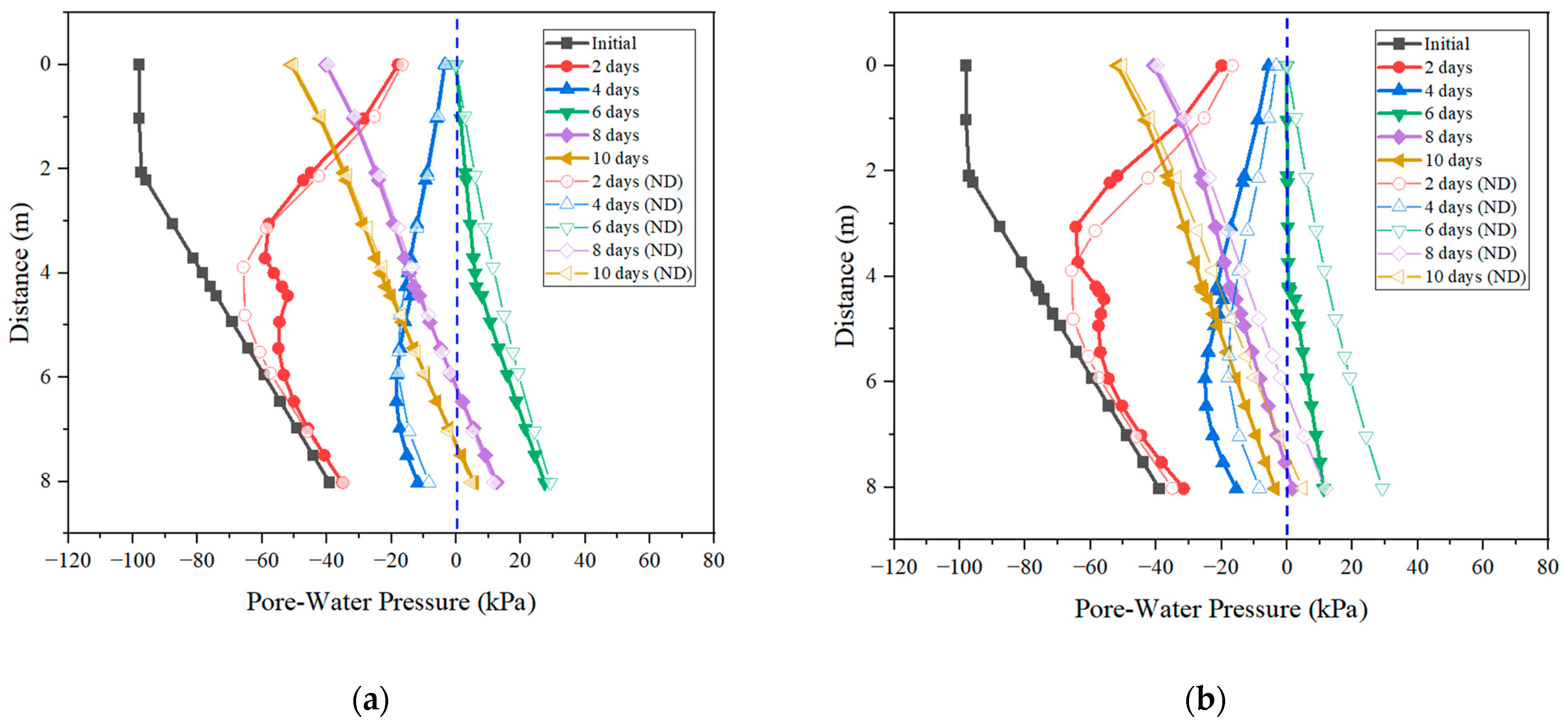
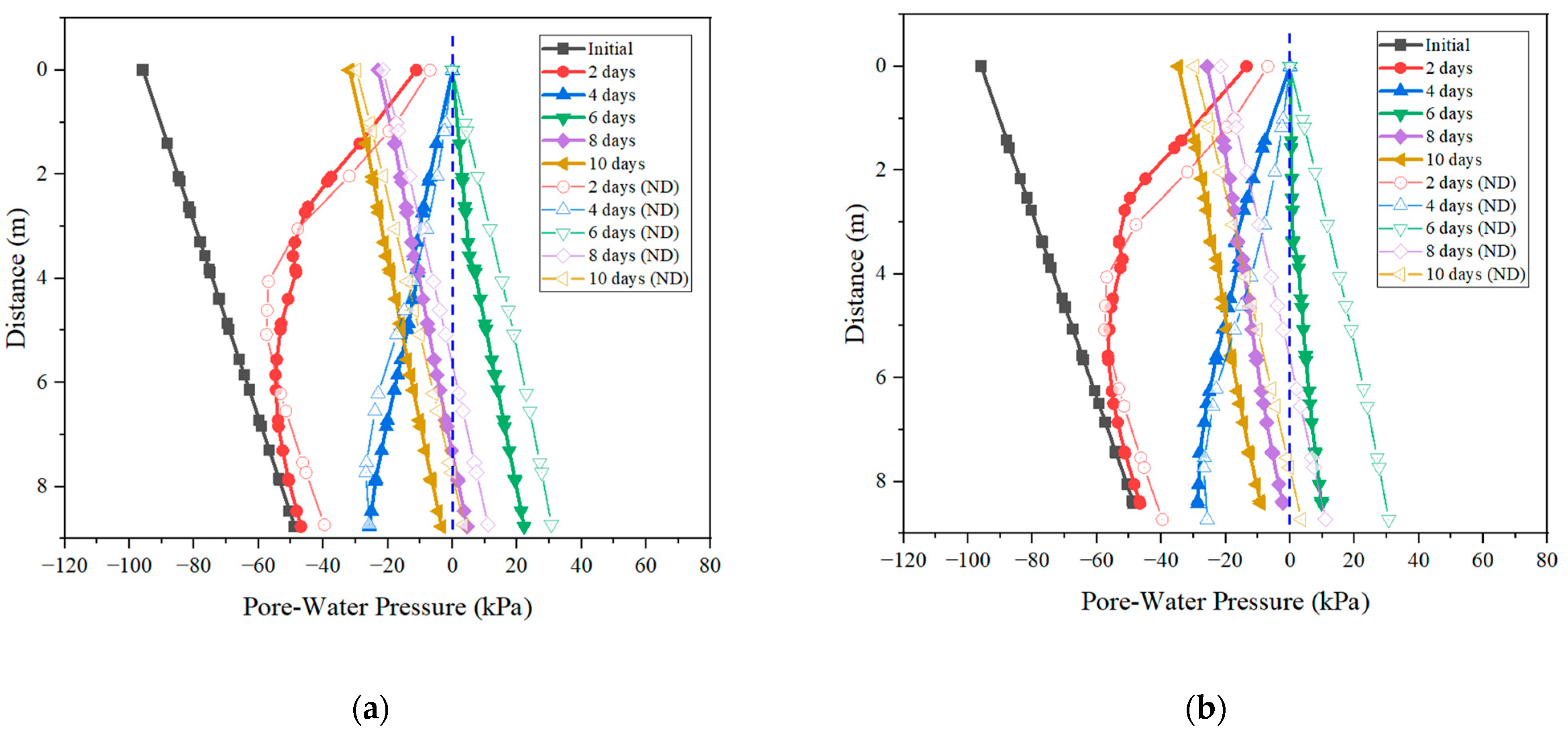
Figure 9, Figure 10 and Figure 11 illustrate the distribution of pore-water pressure on three sections (Sections 1–3) for the scenarios of the pipe at the middle of the slope and pipes at the middle and the toe of the slope, respectively.
Figure 5, Figure 6, Figure 7, Figure 9, Figure 10 and Figure 11 show that the horizontal pipe placed near the toe has better performance in discharging the infiltrated water than that placed in the middle of the slope.

5. Conclusions

This study investigates the effectiveness of horizontal drains in discharging infiltrated water under constant rainfall conditions. Numerical modeling is utilized to analyze the impact of drain length, angle, and location on pore-water pressure distribution within the slope. The results reveal that the studied pipe lengths of 4 m and 7 m do not significantly impact pore-water pressure distribution in those three sections. It is evident that a horizontal drain length of 10 m offers optimal efficiency in mitigating pore-water pressure. Based on the results of the numerical analysis, an optimal length of 1 Hs is recommended. This observation aligns with findings from Cai et al. [16], who noted that beyond a certain critical length, variations in pipe length will not significantly influence reductions in the safety of the slope or in subsurface water.
The inclination angle markedly affects drainage performance, and an optimal angle of 10–15 degrees maximizes the drainage interface area. Additionally, as highlighted by Santi et al. [33], shallower angles are beneficial as they lead to a reduced potential groundwater level by letting the water flow downward naturally. A strategic placement of drains at the slope toe and mid-slope provides the most uniform pore-water pressure reduction across the slope. Dual horizontal drains further improve drainage capacity compared to a single-drain configuration for high slopes.

Author Contributions

Conceptualization, Q.Z. and A.S.; methodology, X.Z. and Z.G.; software, K.X. and X.Z.; validation, H.W., Q.Z. and A.S.; formal analysis, K.X.; investigation, H.W.; resources, H.W. and Y.S.C.; data curation, X.Z.; writing—original draft preparation, K.X.; writing—review and editing, X.Z.; visualization, K.X.; supervision, Q.Z.; project administration, H.W.; funding acquisition, H.W. All authors have read and agreed to the published version of the manuscript.

Funding

This research was funded by National Nature Science Foundation of China, grant number No. 52078128, Enterprise Development Grant from Enterprise Singapore (Co-innovation Program): CIP-2207-CN1064.

Institutional Review Board Statement

Not applicable.

Informed Consent Statement

Not applicable.

Data Availability Statement

No new data were created or analyzed in this study. Data sharing is not applicable to this article.

Conflicts of Interest

The authors declare no conflict of interest.

References

  1. Collins, B.D.; Znidarcic, D. Stability Analyses of Rainfall Induced Landslides. J. Geotech. Geoenvironmental Eng. 2004, 130, 362–372. [Google Scholar] [CrossRef]
  2. Oh, S.; Lu, N. Slope Stability Analysis under Unsaturated Conditions: Case Studies of Rainfall-Induced Failure of Cut Slopes. Eng. Geol. 2015, 184, 96–103. [Google Scholar] [CrossRef]
  3. Cho, S.E.; Lee, S.R. Instability of Unsaturated Soil Slopes Due to Infiltration. Comput. Geotech. 2001, 28, 185–208. [Google Scholar] [CrossRef]
  4. Kim, J.; Jeong, S.; Park, S.; Sharma, J. Influence of Rainfall-Induced Wetting on the Stability of Slopes in Weathered Soils. Eng. Geol. 2004, 75, 251–262. [Google Scholar] [CrossRef]
  5. Leroueil, S. Natural Slopes and Cuts: Movement and Failure Mechanisms. Géotechnique 2001, 51, 197–243. [Google Scholar] [CrossRef]
  6. Dai, F.C.; Lee, C.F. Frequency-Volume Relation and Prediction of Rainfall-Induced Landslides. Eng. Geol. 2001, 59, 253–266. [Google Scholar] [CrossRef]
  7. Tsaparas, I.; Rahardjo, H.; Toll, D.G.; Leong, E.C. Controlling Parameters for Rainfall-Induced Landslides. Comput. Geotech. 2002, 29, 1–27. [Google Scholar] [CrossRef]
  8. Ng, C.W.W.; Shi, Q. A Numerical Investigation of the Stability of Unsaturated Soil Slopes Subjected to Transient Seepage. Comput. Geotech. 1998, 22, 1–28. [Google Scholar] [CrossRef]
  9. Zhang, L.L.; Zhang, J.; Zhang, L.M.; Tang, W.H. Stability Analysis of Rainfall-Induced Slope Failure: A Review. Proc. Inst. Civ. Eng.—Geotech. Eng. 2011, 164, 299–316. [Google Scholar] [CrossRef]
  10. Robinson, J.D.; Vahedifard, F.; AghaKouchak, A. Rainfall-Triggered Slope Instabilities under a Changing Climate: Comparative Study Using Historical and Projected Precipitation Extremes. Can. Geotech. J. 2017, 54, 117–127. [Google Scholar] [CrossRef]
  11. Greenwood, J.R.; Norris, J.E.; Wint, J. Assessing the Contribution of Vegetation to Slope Stability. Proc. Inst. Civ. Eng.—Geotech. Eng. 2004, 157, 199–207. [Google Scholar] [CrossRef]
  12. Won, J.; You, K.; Jeong, S.; Kim, S. Coupled Effects in Stability Analysis of Pile–Slope Systems. Comput. Geotech. 2005, 32, 304–315. [Google Scholar] [CrossRef]
  13. Reubens, B.; Poesen, J.; Danjon, F.; Geudens, G.; Muys, B. The Role of Fine and Coarse Roots in Shallow Slope Stability and Soil Erosion Control with a Focus on Root System Architecture: A Review. Trees 2007, 21, 385–402. [Google Scholar] [CrossRef]
  14. Royster, D.L. Horizontal Drains and Horizontal Drilling: An Overview. Transp. Res. Rec. 1980, 783, 16–20. [Google Scholar]
  15. Rahardjo, H.; Hritzuk, K.J.; Leong, E.C.; Rezaur, R.B. Effectiveness of Horizontal Drains for Slope Stability. Eng. Geol. 2003, 69, 295–308. [Google Scholar] [CrossRef]
  16. Cai, F.; Ugai, K.; Wakai, A.; Li, Q. Effects of Horizontal Drains on Slope Stability under Rainfall by Three-Dimensional Finite Element Analysis. Comput. Geotech. 1998, 23, 255–275. [Google Scholar] [CrossRef]
  17. Nagahara, H.; Fujiyama, T.; Ishiguro, T.; Ohta, H. FEM Analysis of High Airport Embankment with Horizontal Drains. Geotext. Geomembr. 2004, 22, 49–62. [Google Scholar] [CrossRef]
  18. Rahardjo, H.; Santoso, V.A.; Leong, E.C.; Ng, Y.S.; Hua, C.J. Performance of Horizontal Drains in Residual Soil Slopes. Soils Found. 2011, 51, 437–447. [Google Scholar] [CrossRef]
  19. Argunhan-Atalay, C.; Yazicigil, H.; Ekmekci, M. Assessment of Performance of Horizontal Drains in an Open Pit Mine in Eastern Turkey. Environ. Earth Sci. 2021, 80, 108. [Google Scholar] [CrossRef]
  20. Lakruwan, M.; Oikawa, H.; Kamura, A.; Kazama, M. Experimental Evaluation of Effect of Perforation Arrangement on Performance of Horizontal Drains in Landslide Mitigation. Landslides 2021, 18, 3707–3714. [Google Scholar] [CrossRef]
  21. Cook, D.I.; Santi, P.M.; Higgins, J.D. 2007 AEG Student Professional Paper: Graduate Division: Horizontal Landslide Drain Design: State of the Art and Suggested Improvements. Environ. Eng. Geosci. 2008, 14, 241–250. [Google Scholar] [CrossRef]
  22. Forrester, K. Subsurface Drainage for Slope Stabilization; American Society of Civil Engineers: Reston, VA, USA, 2001; ISBN 978-0-7844-0016-6. [Google Scholar]
  23. Fall, M.; Azzam, R.; Noubactep, C. A Multi-Method Approach to Study the Stability of Natural Slopes and Landslide Susceptibility Mapping. Eng. Geol. 2006, 82, 241–263. [Google Scholar] [CrossRef]
  24. Cook, D.I.; Santi, P.M.; Higgins, J.D. Prediction of Piezometric Surfaces and Drain Spacing for Horizontal Drain Design. Landslides 2012, 9, 547–556. [Google Scholar] [CrossRef]
  25. Sari, P.T.K. The Performance of Horizontal Drain as a Landslide Mitigation Strategy. In Proceedings of the 5th International Conference on Rehabilitation and Maintenance in Civil Engineering, ICRMCE 2021, Surakarta, Indonesia, 8–9 July 2021; Kristiawan, S.A., Gan, B.S., Shahin, M., Sharma, A., Eds.; Springer Nature: Singapore, 2023; pp. 449–456. [Google Scholar]
  26. Cuomo, S.; Della Sala, M. Rainfall-Induced Infiltration, Runoff and Failure in Steep Unsaturated Shallow Soil Deposits. Eng. Geol. 2013, 162, 118–127. [Google Scholar] [CrossRef]
  27. Rahardjo, H.; Santoso, V.A.; Leong, E.C.; Ng, Y.S.; Hua, C.J. Numerical Analyses and Monitoring Performance of Residual Soil Slopes. Soils Found. 2011, 51, 471–482. [Google Scholar] [CrossRef]
  28. Rahimi, A.; Rahardjo, H.; Leong, E.-C. Effect of Antecedent Rainfall Patterns on Rainfall-Induced Slope Failure. J. Geotech. Geoenvironmental Eng. 2011, 137, 483–491. [Google Scholar] [CrossRef]
  29. GEO-SLOPE International Ltd. Seepage Modeling with SEEP/W; An Engineering Methodology June 2015 ed.; GEO-SLOPE International Ltd.: Calgary, AB, Canada, 2015. [Google Scholar]
  30. Liu, Y.; Tian, G.; Wang, S.; Satyanaga, A.; Zhai, Q. Parametric Analysis of Rainfall-Induced Loess Soil Slope Due to the Rainwater Infiltration. Urban Sci. 2022, 6, 54. [Google Scholar] [CrossRef]
  31. Zhai, Q.; Rahardjo, H. Determination of Soil–Water Characteristic Curve Variables. Comput. Geotech. 2012, 42, 37–43. [Google Scholar] [CrossRef]
  32. Fredlund, D.G.; Xing, A.; Huang, S. Predicting the Permeability Function for Unsaturated Soils Using the Soil-Water Characteristic Curve. Can. Geotech. J. 1994, 31, 533–546. [Google Scholar] [CrossRef]
  33. Santi, P.M.; Dale Elifrits, C.; Liljegren, J.A. Design and Installation of Horizontal Wick Drains for Landslide Stabilization. Transp. Res. Rec. 2001, 1757, 58–66. [Google Scholar] [CrossRef]
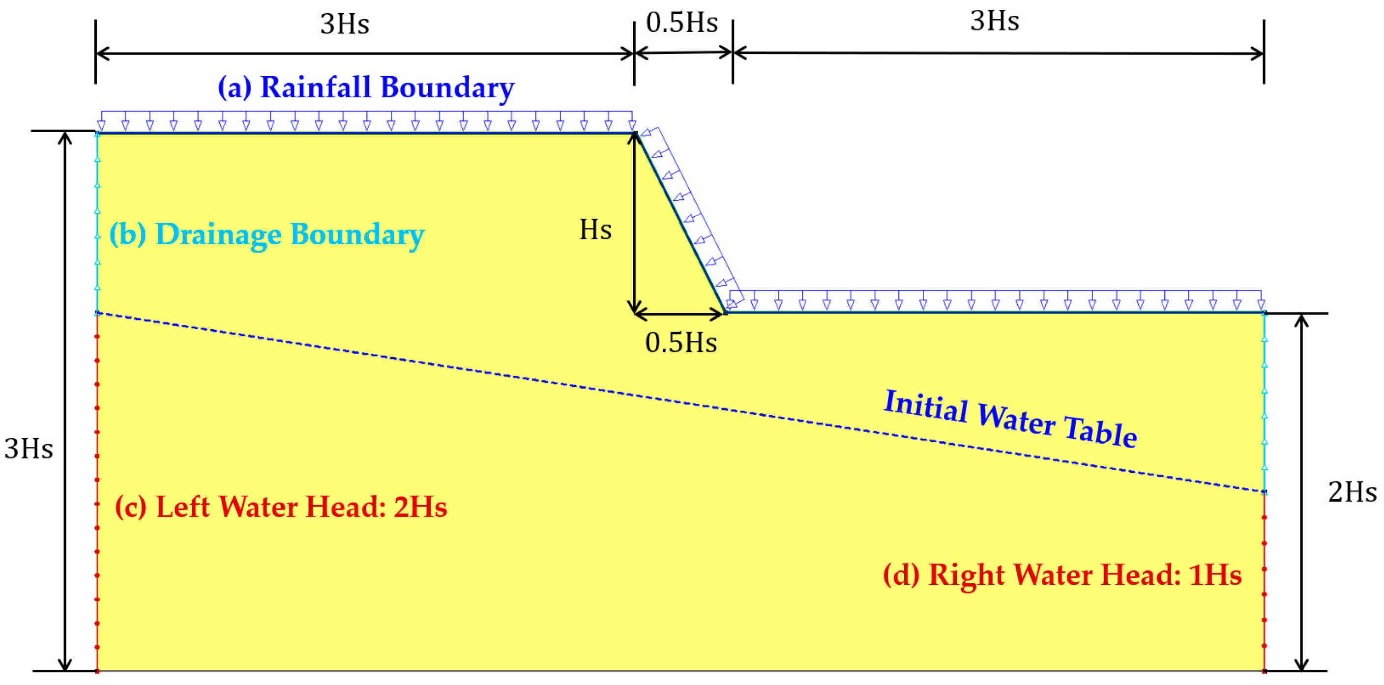
Figure 1. Geometric and boundary conditions of the numerical model.
Sustainability 15 14163 g001
Figure 2. Positioning of the varying analysis sections within the slope.
Sustainability 15 14163 g002
Figure 3. Pore-water pressure distribution across three sections of the slope under no-drainage condition: (a) Section 1; (b) Section 2; (c) Section 3.
Sustainability 15 14163 g003
Figure 4. Impact of horizontal drain length on pore-water pressure in slopes: (ad) comparison of 4 m, 7 m, 10 m, and 13 m in Section 1; (eh) comparison of 4 m, 7 m, 10 m, and 13 m in Section 2; (il) comparison of 4 m, 7 m, 10 m, and 13 m in Section 3.
Sustainability 15 14163 g004aSustainability 15 14163 g004bSustainability 15 14163 g004c
Figure 5. Impact of horizontal drain inclination angle on pore-water pressure in Section 1: (a) 5° horizontal drain; (b) 10° horizontal drain; (c) 15° horizontal drain.
Sustainability 15 14163 g005aSustainability 15 14163 g005b
Figure 6. Impact of horizontal drain inclination angle on pore-water pressure in Section 2: (a) 5° horizontal drain; (b) 10° horizontal drain; (c) 15° horizontal drain.
Sustainability 15 14163 g006
Figure 7. Impact of horizontal drain inclination angle on pore-water pressure in Section 3: (a) 5° horizontal drain; (b) 10° horizontal drain; (c) 15° horizontal drain.
Sustainability 15 14163 g007
Figure 8. Displacement position of horizontal drains: (a) at the toe of the slope; (b) at the middle of the slope; (c) in both positions.
Sustainability 15 14163 g008
Figure 9. Impact of horizontal drain placement position on pore-water pressure in Section 1: (a) at the middle of the slope; (b) at both positions.
Sustainability 15 14163 g009
Figure 10. Impact of horizontal drain placement position on pore-water pressure in Section 2: (a) at the middle of the slope; (b) at both positions.
Sustainability 15 14163 g010
Figure 11. Impact of horizontal drain placement position on pore-water pressure in Section 3: (a) at the middle of the slope; (b) at both positions.
Sustainability 15 14163 g011
Table 1. Illustration of SWCC fitting parameters and the saturated hydraulic conductivity of typical residual soil.
Soil TypeSWCC Fitting ParametersSaturated Hydraulic Conductivity
a (kPa)nm θ s (%) k s
Residual Soil10011451 × 10−6
Table 2. Illustration of the scenarios for the numerical analyses.
Research PlansHorizontal Drain Layout Plan
Length (m)Angle (°)Location
Case 1Case 1-140Toe
Case 1-270Toe
Case 1-3100Toe
Case 1-4130Toe
Case 2Case 2-1105Toe
Case 2-21010Toe
Case 2-31015Toe
Case 3Case 3-1105Toe
Case 3-2105Mid-Slope
Case 3-3105Both
Disclaimer/Publisher’s Note: The statements, opinions and data contained in all publications are solely those of the individual author(s) and contributor(s) and not of MDPI and/or the editor(s). MDPI and/or the editor(s) disclaim responsibility for any injury to people or property resulting from any ideas, methods, instructions or products referred to in the content.