Next Article in Journal
An Eco-Innovative Green Design Method using the Theory of Inventive Problem Solving and Importance–Performance Analysis Tools—A Case Study of Marker Pen Manufacturing
Previous Article in Journal
Breaking Triopoly to Achieve Sustainable Smart Digital Infrastructure Based on Open-Source Diffusion Using Government–Platform–User Evolutionary Game
Previous Article in Special Issue
XGBoost–SFS and Double Nested Stacking Ensemble Model for Photovoltaic Power Forecasting under Variable Weather Conditions
 
 
Correction published on 3 July 2024, see Sustainability 2024, 16(13), 5680.
Article

Material Tradeoff of Rotor Architecture for Lightweight Low-Loss Cost-Effective Sustainable Electric Drivetrains

1
Department of Electromechanical, Systems and Metal Engineering, Ghent University, 9000 Ghent, Belgium
2
FlandersMake@UGent, Core Lab MIRO, 3001 Leuven, Belgium
Sustainability 2023, 15(19), 14413; https://doi.org/10.3390/su151914413
Submission received: 5 September 2023 / Revised: 26 September 2023 / Accepted: 27 September 2023 / Published: 1 October 2023 / Corrected: 3 July 2024

Abstract

:
The art of successful design of high-speed electrical machines comes with many challenges in mass, size, reliability, and energy efficiency. Material engineering of electrical machines has been identified as a key solution for more power dense electric drivetrains. One of the main challenges at high speed is the eddy-current losses in the active electromagnetic parts especially magnetic materials and permanent magnets (PM). This study is devoted to the materials selection of the PM rotor using multidisciplinary design optimization for a high-speed electric drivetrain. Besides AC loss minimization, more disciplines are considered such as minimization of weight, and cost. Different laminations are investigated with different magnetic properties as well as cost. Additionally, different PMs are optimized considering low-cost ferrite and high-coercivity permanent magnets (HCPMs). Moreover, the optimal materials with the best balance between loss, weight, cost, and torque ripple are identified. Finally, different rotor designs are compared using the same stator configuration as the conventional machine. Its electromagnetic performance is measured and compared with the conventional designs. The optimal design results in 8% extra torque with at least 20% weight reduction.

1. Introduction

Nowadays, the engineering of a high-performing electrical machine requires many considerations during the early-stage design process such as limitations in design, environmental conditions, international standards, customer needs, and manufacturability. At the end, a successful design should have an optimal balance between the performance and the cost of manufacturing. The materials used in an electrical machine impose limitations in design such as saturation in laminations, current density in conductors, and temperature of the insulation. Therefore, special attention is given to the selection of materials with the necessary properties during the design process of the machine.
The importance of material selection in the design of electrical machines cannot be overstated, as it significantly impacts their performance, efficiency, and cost-effectiveness [1]. Furthermore, the choice of materials plays a pivotal role in addressing contemporary challenges such as environmental sustainability and energy efficiency. In recent years, research efforts have focused on exploring innovative materials and their applications in electric drivetrains. These materials encompass a wide range of components, from static elements like housings and bearings to active electromagnetic components like laminations, conductors, and permanent magnets. The optimization of these materials is integral to achieving the desired balance between machine performance and manufacturing costs [2,3,4,5].
Sustainability and environmental concerns surrounding FeSi laminations in electrical machines are of growing importance [6]. These concerns span various stages of the laminations’ life cycle, from raw material extraction to disposal. The production of electrical steel involves resource-intensive processes, including iron ore extraction and silicon alloy processing, contributing to energy consumption, water use, and greenhouse gas emissions. Additionally, waste generation and improper disposal of byproducts pose environmental challenges. Transporting laminations over long distances further adds to their carbon footprint. To address these concerns, various strategies are being employed. Life cycle assessments help identify areas for improvement, while recycling efforts promote a circular economy approach. Researchers are exploring alternative materials that offer similar magnetic properties with reduced environmental impact. Energy efficiency, a primary purpose of FeSi laminations, aligns with sustainability goals by reducing energy consumption in electrical machines. Manufacturers are adopting green practices, such as renewable energy use and waste reduction, while regulatory compliance ensures adherence to environmental standards. Additionally, raising consumer and industry awareness regarding sustainable choices is essential. In summary, mitigating the environmental impact of FeSi laminations involves improving production processes, recycling, and adopting sustainable practices throughout the supply chain and product life cycle. This holistic approach aims to minimize the environmental footprint of electrical machines, contributing to a more eco-friendly and sustainable energy infrastructure. With this being said, material engineering of lamination materials can help in the downsizing of the electrical machine as well as improving its energy consumption [7].
Numerous studies in the literature have addressed the crucial aspect of material selection for electric machines [8]. In [9], the role of advanced materials is discussed for unconventional applications. Advanced magnetic and conducting materials, advanced PMs, and advanced insulation systems have been compared. In [10], different windings materials are introduced including additively manufactured coils. Also, a comparison between winding has been reported in [11,12]. In [13], the thermal and electromagnetic impacts of using different steel laminations on the machine performance have been studied. Furthermore, in [14], the impact of manufacturing post processes (cutting and stacking) is investigated on the magnetic laminations. The fundamental calculations for choice of material in the design of PMs is first introduced in [15]. Additionally, in [16], a shape optimization method is introduced for PMs to improve the gap flux density. To the best of authors knowledge, there is no study that considered material tradeoff between all active magnetic components of the rotor.
This paper introduces the material tradeoff of magnetic materials in the electrical machine. First, the rotor architecture is investigated using different barrier shapes. Then, an advanced parametric model is created for multi-disciplinary optimization targeting the minimization of AC loss, weight, cost, and torque ripples. Targeting an electric drivetrain, the optimal dimensions as well as lamination, and PM materials are selected. Additionally, different rotor designs are prototyped and tested. Finally, the electromagnetic performance of the optimal design is measured and compared with conventional designs.

2. Rotor Barrier Shape Profiling

A three-phase PM-assisted synchronous reluctance machine (SynRM) is selected as the reference model of this study. The machine configuration and finite element modeling of the full design are shown in Figure 1. A 48-slot stator is used with parallel-sided slot shape in order to suit a hairpin winding configuration. The reference rotor design has 8 poles with a double-V (dV) magnet shape.
The focus on SynRM and rotor design in this study stems from several key motivations and considerations:
  • Industry Relevance: SynRM technology has gained significant traction in recent years, particularly in industrial and automotive applications, due to its potential for high efficiency, reduced energy consumption, and sustainability. The drive towards more energy-efficient and environmentally friendly solutions intensifies, leading to a growing interest in optimizing SynRMs for various applications. This study aligns with this industry trend by addressing critical aspects of SynRM design.
  • Challenges in Rotor Design: The rotor is a pivotal component of electric motors, significantly influencing their performance, efficiency, and cost-effectiveness. The rotor’s design intricacies, including material selection, dimensions, and barrier angles for q-magnets, present complex optimization challenges. By focusing on rotor design, this study aims to provide insights into how these design parameters impact motor performance and how they can be optimized for superior results.
  • Multidisciplinary Approach: A multidisciplinary design optimization (MDO) approach is adopted to address the complexities of rotor design. This approach enables the simultaneous consideration of multiple objectives, including minimizing losses, weight, cost, and torque ripples. By concentrating on SynRM rotor design, this study showcases the applicability and effectiveness of MDO in the context of electric machine design, which has broader implications for the field.
  • Material Tradeoff Analysis: This study delves into the material tradeoffs within the rotor, considering various active electromagnetic components, such as laminations, conductors, and permanent magnets. This comprehensive analysis fills a gap in the literature, as prior studies have often focused on individual rotor components in isolation. The approach allows for a more holistic perspective on material selection.
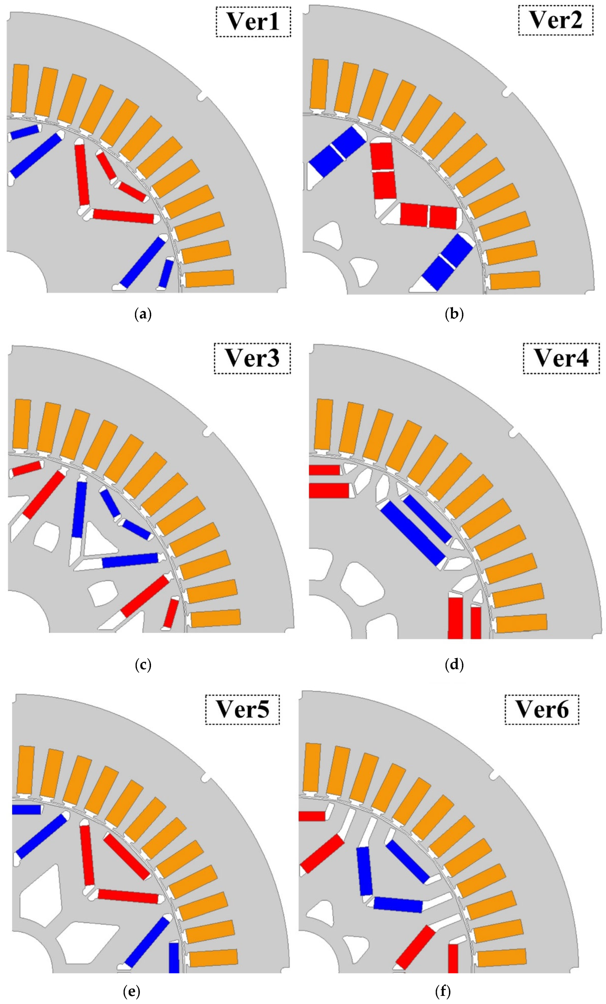
Five additional rotor designs are investigated for the same stator geometry. The average area of permanent magnets (PMs) per pole remains unchanged across all six designs. The original design (Ver1) features a dV shape without any empty spaces in the back iron as shown in Figure 2a. These empty spaces could be utilized to reduce the weight of the rotor. However, implementing this approach poses a significant risk of iron saturation and demagnetization of the PMs. In the second design (Ver2) in Figure 2b, a single-V (sV) shape is used, and an air space is incorporated in the back iron. In the third design (Ver3), illustrated in Figure 2c, a modified dV (mdV) shape is utilized by incorporating a deeper PM barrier and removing additional back iron. In the fourth design (Ver4), presented in Figure 2d, a double-U (dU) shape is employed, with the PMs integrated along the direct axis (d-axis). In the fifth design (Ver5), showcased in Figure 2e, a delta (DL) shape is utilized, incorporating the PMs along both the d-axis and q-axis. Finally, in the 6th design (Ver6) in Figure 2f, a hybrid design referred to as UV shape is employed, combining elements of both U-shape and V-shape designs. In this design, the PMs exist along both the d-axis and q-axis arranged in a delta shape.
The finite element simulations of the six rotor designs are compared under the same materials and operating conditions, as shown in Figure 3. The simulation results are summarized in Table 1. As can be seen, in the first design, there is a significant imbalance in the flux density distribution of the rotor iron. Despite having the lowest PM demagnetization risk, the reference design is not the optimal choice for achieving higher average torque. The second version (ver2) yields nearly the same average torque with relatively lower torque ripples. However, PM losses increase significantly by 9%, and the maximum flux density is much higher than that of the reference case. In the third design (ver3), there is a slight improvement in the average torque. Yet, there is a substantial increase in torque ripples compared to the reference design. In the fourth design (ver4), the rotor yoke iron is much lower than in the reference case. Additionally, the average torque remains nearly the same. However, PM losses and demagnetization are the highest among all designs. In the fifth design (ver5), the average torque increased considerably by 2.2% with lower torque ripples. Nonetheless, the demagnetization risk is still higher than in the reference case. Finally, in the 6th design (ver6), the average torque improved remarkably by 4.4%, and PM losses decreased by 5%, with demagnetization and ripple levels nearly unchanged. Furthermore, the saturated area is the lowest, despite having air spaces in the rotor. Hence, this shape is selected for further investigation and optimization.

3. Benchmarked Electrical Machine

3.1. Material Tradeoff

Synchronous Reluctance Machines (SynRMs) are gaining prominence in various industrial applications due to their energy efficiency and robust performance characteristics. The choice of materials for the rotor construction is a critical factor that directly influences the machine’s efficiency and cost. This article explores the material tradeoff and selection criteria for SynRM rotors, particularly focusing on the comparison between Synchronous Reluctance Machine Rotors and Permanent Magnet Rotors. The study aims to provide insights into the design and optimization of SynRMs for enhanced performance and sustainability.
Synchronous Reluctance Machines have emerged as a promising alternative to traditional induction and permanent magnet synchronous machines due to their simplified construction, reduced cost, and improved efficiency. The rotor design of SynRMs plays a pivotal role in determining their operational characteristics. This article delves into the tradeoffs and selection criteria of materials for SynRM rotors, with a particular emphasis on choosing between Synchronous Reluctance Machine Rotors and Permanent Magnet Rotors.
SynRM rotors are typically constructed using laminated steel cores. The choice of rotor material primarily depends on factors such as magnetic flux density, electrical resistivity, and mechanical strength. Low-carbon steel laminations are commonly used due to their favorable magnetic properties and cost-effectiveness. However, the tradeoff lies in the need for increased rotor dimensions to achieve the desired magnetic performance, potentially leading to higher losses and manufacturing costs.
Permanent magnet (PM) rotors are characterized by high magnetic flux density, resulting in superior performance and efficiency compared to SynRM rotors. Neodymium iron boron (NdFeB) magnets are the preferred choice for PM rotors due to their outstanding magnetic properties. However, the tradeoff here is that these rare-earth magnets are costly, subject to supply chain uncertainties, and pose environmental concerns. Additionally, the disposal of rare-earth magnets can be challenging.
The choice between SynRM and PM rotors depends on the specific performance requirements of the application. For applications demanding high efficiency and power density, PM rotors are preferred. SynRM rotors may be suitable for applications prioritizing cost-effectiveness over maximum performance.
SynRM rotors are generally more cost-effective in terms of material and manufacturing costs. If cost is a primary concern, SynRM rotors may be the preferred choice.
PM rotors, particularly those utilizing rare-earth magnets, raise environmental concerns due to resource scarcity and extraction-related environmental issues. SynRM rotors, with their simpler materials and reduced reliance on rare earths, may be considered a more sustainable option. For applications with strict size and weight constraints, PM rotors’ high magnetic flux density allows for compact designs. SynRM rotors may require larger dimensions to achieve comparable performance.
The choice between SynRM Rotors and PM Rotors involves a careful evaluation of performance requirements, cost considerations, sustainability, and size constraints. Each rotor type has its own set of advantages and tradeoffs, making it crucial for designers and engineers to make informed decisions based on the specific needs of their applications. As technology evolves and environmental concerns become more prominent, the selection of rotor materials for SynRMs will continue to be a dynamic and evolving field of study.

3.2. Full Design Optimization

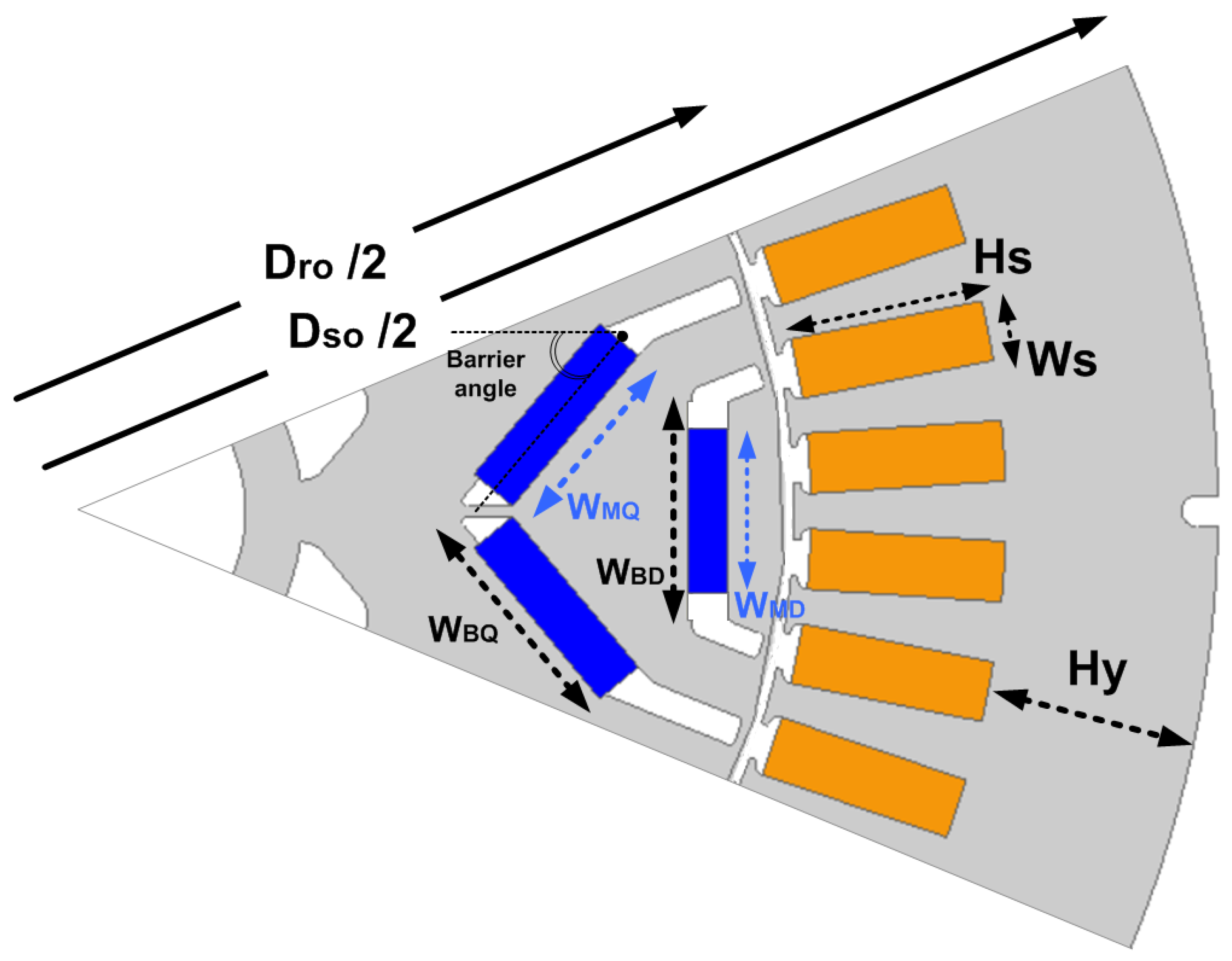
The main dimensions including the stator, rotor, and PMs are highlighted in Figure 4. The specifications of the optimization parameters are listed in Table 2 and Table 3. The stator outer diameter ( D s o ) is maintained at a fixed value. All the other geometries are defined as variables. Among those variables, two main ratios have higher contributions to the machine size, which are aspect ratio ( A R ) and the split ratio ( S R ). The A R is the ratio between the machine stack length ( L s ) and the stator outer diameter ( D s o ). Since the stator outer diameter is fixed, this ratio is mainly dependent on the stack length. The S R is the ratio between the rotor outer diameter ( D r o ) and the stator outer diameter ( D s o ). This ratio depends mainly on the rotor outer diameter. For the magnets, two main ratios define the magnet sizes, which are M D and M Q .
The optimization flowchart for the complete machine is shown in Figure 5. The main target is to identify the optimal dimensions of the baseline machine. First, a fully parametrized model is created using a finite element software. The input variable ranges for the stator, rotor, and PMs are defined including dimensions and materials. In the optimization process, the dimensions and materials of the PMs are determined simultaneously. Then, the main objective and constraints are specified. There are four objectives of the simulations which are minimizing losses, weight, torque ripples, and cost. The losses are calculated for all the active parts including winding losses, PM losses, and iron losses. The weight is calculated for the overall machine based on the material mass density and volume. The cost includes the material cost and the processing cost such as cutting, stacking, assembly, etc.
Four constraints are selected to identify passed and failed samples. The first and second constraints are that the machine rating at base speed and top speed must be equal to or higher than the target value.
The third constraint is regarding the temperature limits which are selected based on the electrical insulation of the windings and the PM maximum working temperature. Regular neodymium magnets can operate efficiently up to 80°C but above this level, they will experience irrecoverable losses in performance, and they start to lose their magnetic output [17]. Eventually, structural changes occur to magnet material and the magnetic properties are permanently lost. For high-temperature applications, samarium cobalt and high-temperature neodymium magnets should be considered. For instance, grades like the UH rating have a maximum working temperature of 180 °C [18]. The maximum operating temperature for each grade is listed in Table 4.
The fourth constraint is to have zero reverse field demagnetization in the PMs. This type of demagnetization can occur when an external magnetic field is reversely applied. As a result, the working point is pushed below the knee point of the magnet BH curve. In this situation, the PMs start to lose some of the original remanence ( B r ). Among different PM materials, rare earth PM has the lowest chances of demagnetization due to its very high intrinsic coercive force ( H c ).
In parallel with objective function calculations, we evaluate whether the machine ratings at base speed and top speed meet the target value. This is essential as it ensures that the machine’s power output aligns with the intended application requirements. The final step in our optimization workflow involves the selection of the optimal design from the pool of generated candidates. This step is strategically placed at the end of the workflow for several reasons:
  • Comprehensive Evaluation: By waiting until the end of the optimization process to select the optimal design, we ensure that all generated design candidates have undergone a thorough evaluation against the defined objectives and constraints. This allows us to make an informed decision based on a comprehensive assessment of each candidate’s performance.
  • Trade-off Analysis: Selecting the optimal design at this stage allows us to perform a detailed trade-off analysis. We can consider how each design candidate balances the competing objectives of minimizing losses, weight, torque ripples, and cost. This analysis ensures that the chosen design aligns with the overall goals of the project while considering potential trade-offs between different criteria.
  • Practicality and Feasibility: It is essential to evaluate the practicality and feasibility of the optimal design in real-world applications. At this stage, we can assess factors such as manufacturability, maintenance requirements, and compatibility with existing systems. This evaluation ensures that the selected design is not only theoretically optimal but also viable for implementation.
  • Consideration of External Factors: The selection of the optimal design allows us to take into account external factors that may influence the decision, such as market conditions, regulatory requirements, and customer preferences. This consideration ensures that the chosen design aligns with broader contextual factors that may impact its success.
  • Resources and Documentation: Once the optimal design is selected, we can dedicate the necessary resources to thoroughly document and report on the chosen configuration. This documentation should include detailed specifications, performance characteristics, and any relevant design considerations. This step is essential for communicating the results of the optimization process effectively.
In summary, the workflow is structured to progress from foundational model creation to variable definition, followed by the establishment of objectives and constraints. Subsequently, objective and constraint calculations, machine rating evaluations, and temperature and demagnetization considerations are addressed in a logical sequence. This systematic approach ensures that the optimization process is both guided and well-informed at each stage, ultimately leading to the identification of optimal machine designs. Eventually, incorporating the selection of the optimal design into our optimization workflow emphasizes the importance of making a well-informed and contextually aware decision at the conclusion of the optimization process. It ensures that the chosen design not only meets technical criteria but also aligns with practical considerations and external factors.
The rank of each passed sample is calculated as follows.
R a n k i = 1 4   ( L o s s m i n L o s s i + W e i g h t m i n W e i g h t i + C o s t m i n C o s t i + R i p p l e m i n R i p p l e i )
where
  • Rank_i: This represents the calculated rank for the i-th design candidate, indicating how well it performs compared to others in the optimization process.
  • Loss_min: This term represents the minimum loss among all design candidates, serving as a reference point for assessing the relative loss of the i-th candidate.
  • Loss_i: Refers to the loss associated with the i-th design candidate.
  • Weight_min: This term represents the minimum weight among all design candidates.
  • Weight_i: Denotes the weight of the i-th design candidate.
  • Cost_min: This term signifies the minimum cost among all design candidates.
  • Cost_i: Represents the cost associated with the i-th design candidate.
  • Ripple_min: This term signifies the minimum ripple among all design candidates, offering a benchmark for evaluating the relative ripple of the i-th candidate.
  • Ripple_i: Denotes the ripple associated with the i-th design candidate
The outcomes of the successful design candidates, coupled with their respective rankings, are presented in Figure 6. It is evident that the results exhibit notable variations in terms of losses, weight, and cost, largely influenced by the chosen dimensions and material selections. Among these candidates, the “best-in-class” (BIC) designs emerge as those characterized by superior attributes, boasting low losses, reduced weight, minimal cost, and negligible ripples. Interestingly, despite not achieving the absolute minimum in losses, cost, weight, or ripples individually, the optimal design stands out for its exceptional balance across all four objectives. This balance is a testament to its prowess in simultaneously minimizing losses, weight, cost, and ripples. It exemplifies a holistic approach to design optimization, where the synergistic interaction of these objectives results in an overall superior design. In summary, our study showcases how intricate trade-offs between various design aspects, such as dimensions, materials, and barrier angles, can yield optimal designs that strike an exceptional balance among multiple competing objectives, ultimately leading to high-performance electric drivetrains.
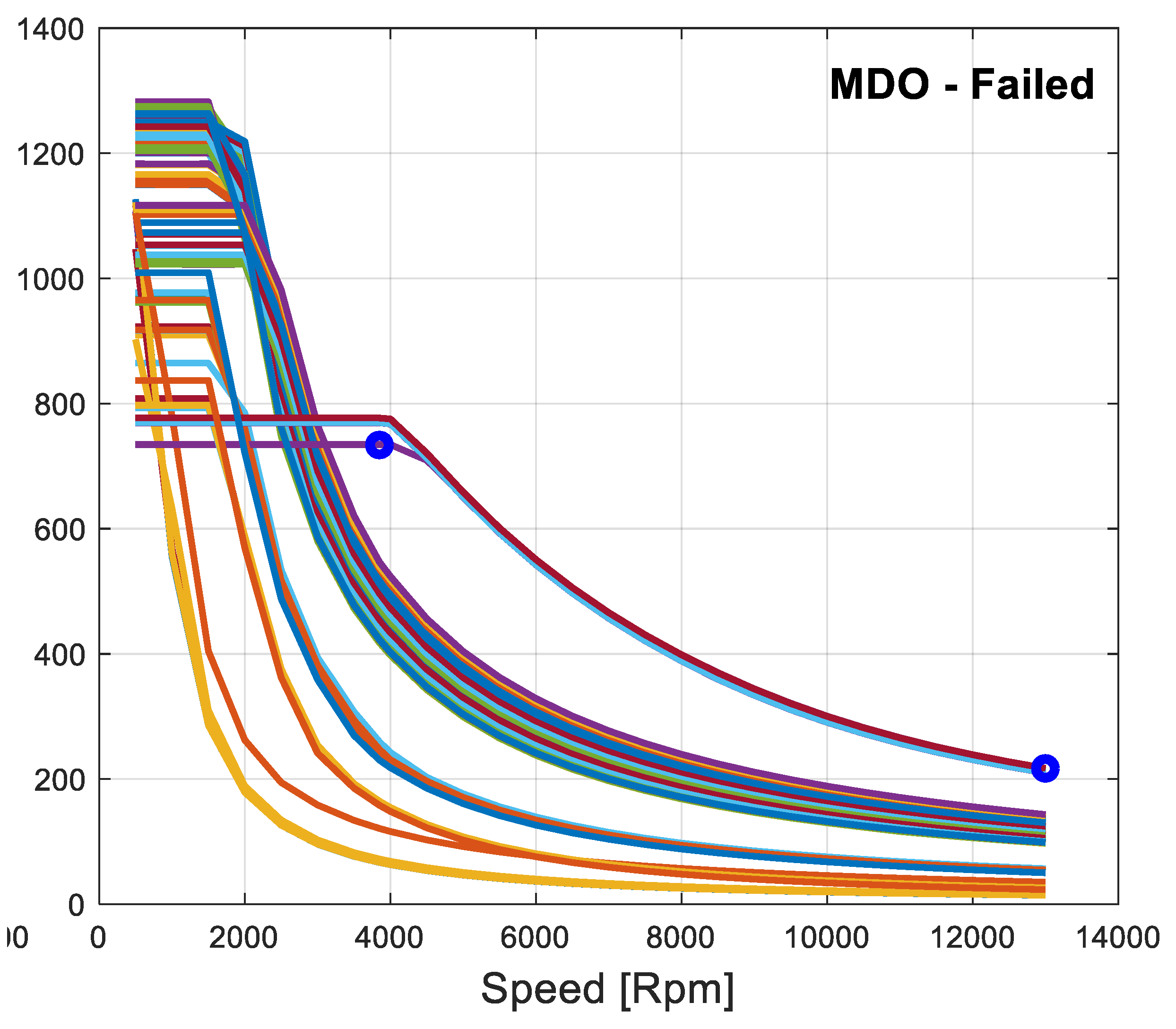
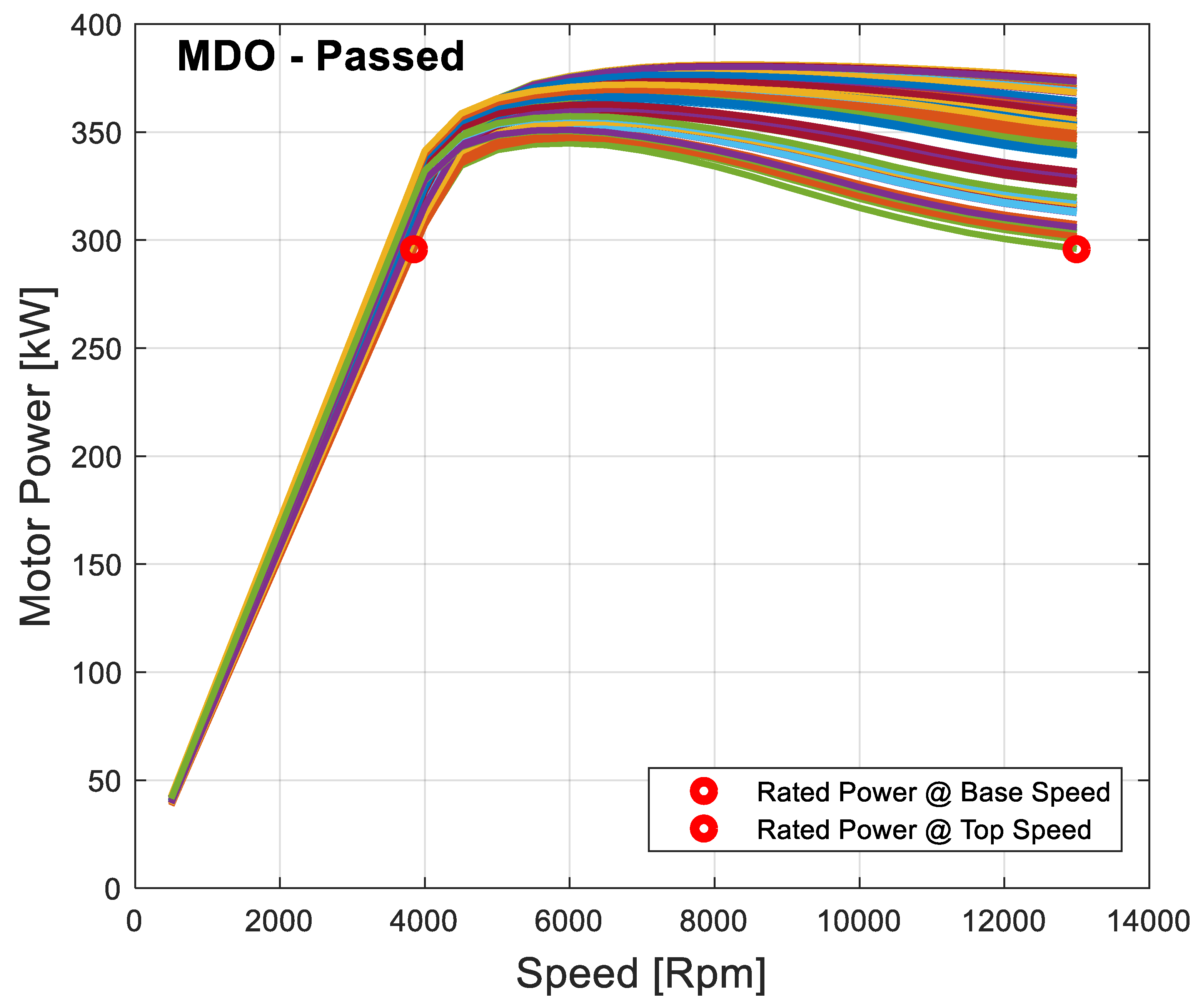
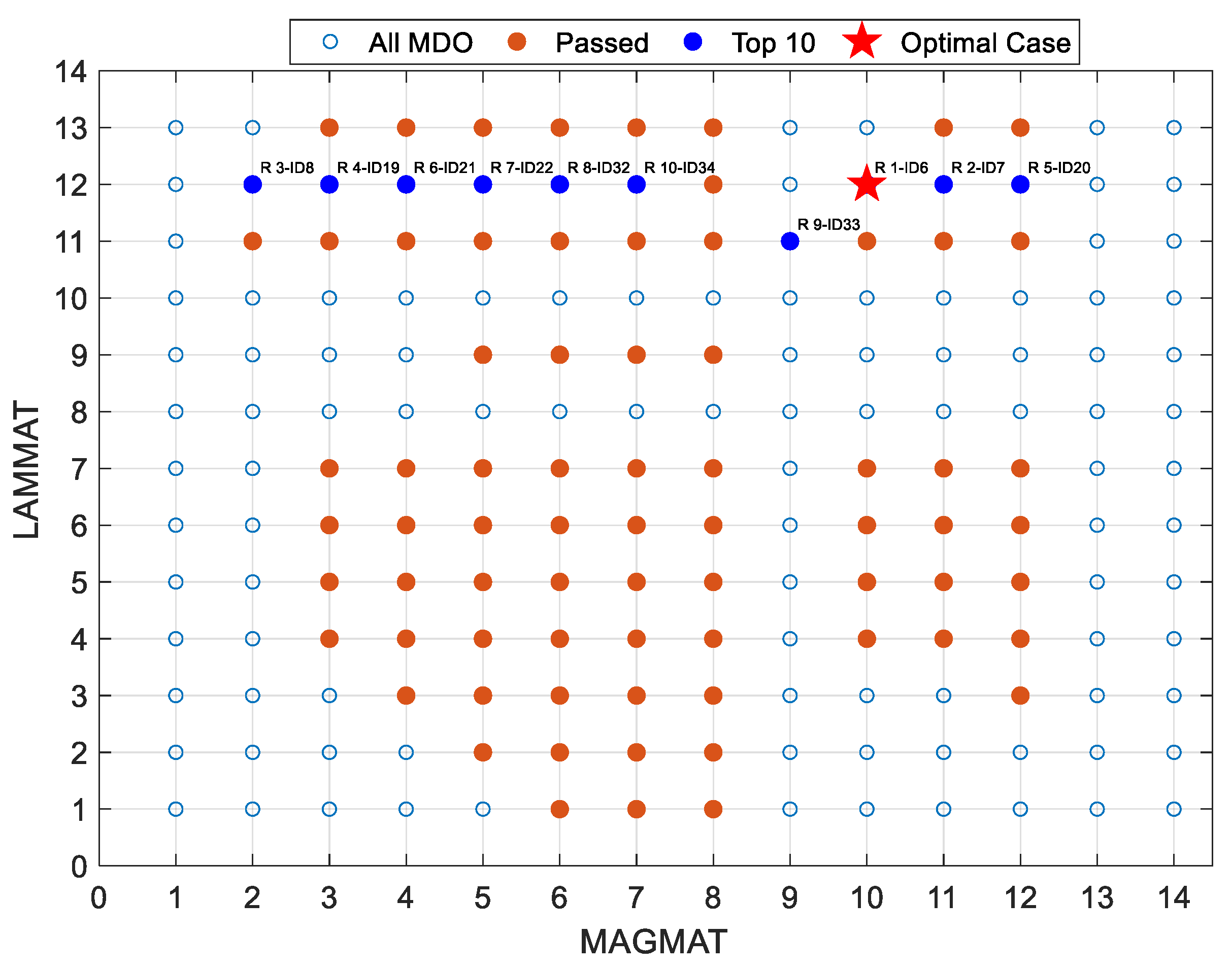
The material tradeoff analysis is started using the objective and constraints in Figure 5. Aiming at higher rank solutions, 182 unique designs are selected from the total number of evaluations using the different combination of materials aforementioned in Table 3. Among the investigated combinations, 82 designs have fulfilled the criteria. Thus, 100 designs failed to achieve the constraints of the ratings, temperature limits, and demagnetization. The torque speed characteristics for both passed and failed samples are shown in Figure 7 and Figure 8. Also, the corresponding power speed profiles are compared in Figure 9 and Figure 10. As can be seen in some failed samples, certain material combinations can achieve the target torque and power requirements. However, the other criteria (thermal or demagnetization) are not fulfilled. Figure 11 shows lamination materials versus magnet materials indicating top-ranked cases. Between the top 10 samples, 10 different MAGMAT can be used. However, only two LAMMAT are among them.
The torque speed characteristics of the top ten combinations are shown in Figure 12. All samples have equal or higher torque than the target value at both base speed and top speed. Yet, a higher torque does not necessarily mean a higher rank, because there are other objectives to meet besides power requirements. Finally, the specifications of the proposed optimal design are listed in Table 5.

4. Prototyping and Measurement Results

Using the optimal dimensions and materials, a PM-assisted SynRM is prototyped using one stator configuration and six different rotor designs. The reference design (Ver1) is shown in Figure 13a along with a 48-slot stator core. A test platform is used to measure the motor performance at low-power conditions as shown in Figure 13b. A drive unit is used to supply the motor with 3-phase currents with variable frequency levels to control the speed. The torque and power are measured using the data acquisition of the DSP MicroLabBox. The corresponding schematic diagram is shown in Figure 13c.
The machine assembly is shown in Figure 14. A distributed winding configuration is employed in the stator using hairpin windings. Each rotor is divided into 6 parts. Half of these parts is mechanically shifted by a swing angle of 5° to reduce the torque ripples.
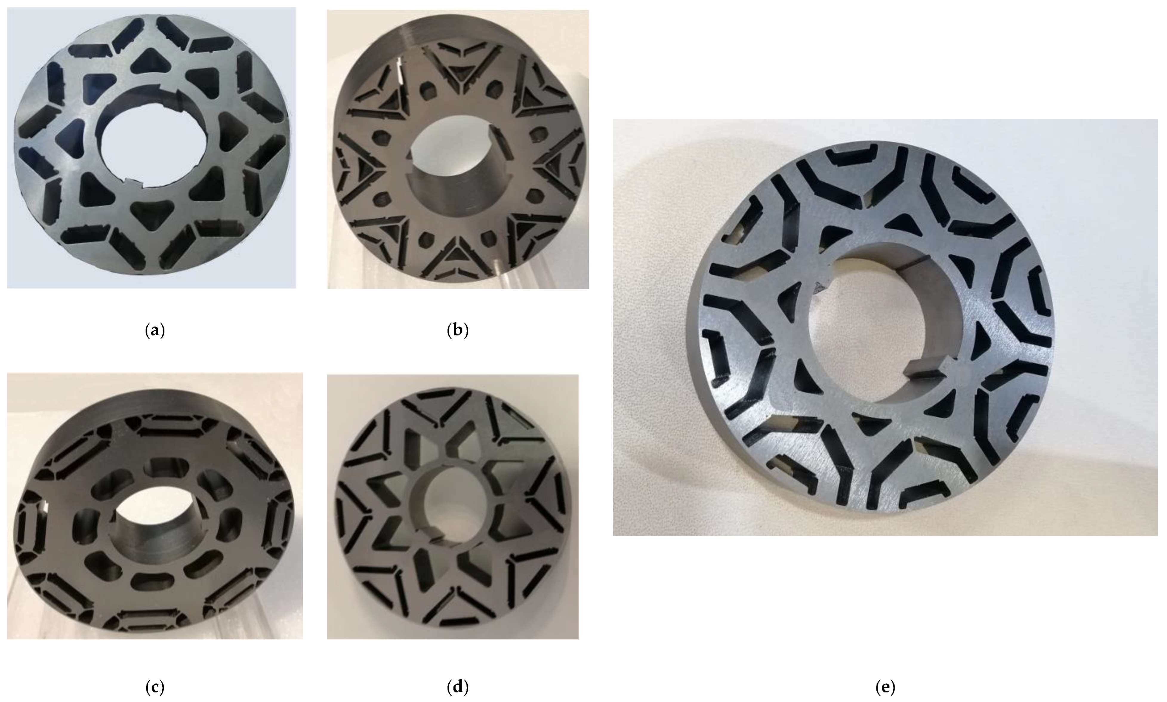
Apart from the reference design, 5 additional rotor designs are prototyped, but not tested, to measure their relevant weight. as shown in Figure 15, which are Ver2, Ver3, Ver4, Ver5, and Ver6, respectively. A comparison between the different rotor designs is listed in Table 6. As can be seen, the Ver6 shape has the highest peak torque. It also combines the highest power density and lowest power losses. Therefore, the Ver6 design is identified as the optimal design. The anticipated performance for the optimal design is shown in Figure 16 based on FE simulation. As can be seen, the required torque at base and top speeds can be achieved. It is also clear that the machine can deliver far higher output power above the base speed compared to the target rated value.
In the second place, The Ver5 shape has also lower power losses compared to the reference design. It has also the lowest rotor weight. In Ver4 and Ver2 rotor shapes, the rotor weight is reduced significantly. However, the power losses increased by about 10% compared to the reference design. In Ver3 rotor shape, the torque density is improved by over 8% and the rotor weight is reduced by at least 6%. Yet, power losses are slightly higher.
To sum up, one of the primary contributions of this paper is the application of a multidisciplinary design optimization approach to the material selection and design of the rotor in high-speed electric drivetrains. By simultaneously considering objectives related to losses, weight, cost, and torque ripples, our MDO methodology enables the identification of designs that strike an optimal balance among these competing factors. This holistic approach results in improved electric drivetrain performance and cost-effectiveness. On the counterpart, the multidisciplinary design optimization process involves a substantial computational effort due to the high number of input and output variables. This complexity may require significant computational resources, limiting its immediate applicability in resource-constrained environments.

5. Conclusions

This paper presented the prototyping and measurement results of a Permanent Magnet (PM)-assisted Synchronous Reluctance Motor (SynRM) with a focus on optimizing rotor design. A material tradeoff is introduced using multi-disciplinary optimization (MDO) of the rotor structure. Aiming at high performance and cost-effectiveness, a SynRM electric drivetrain is optimized using different lamination, and PMs materials. The rotor sizes are optimized using multiple lamination grades with different magnetic properties as well as costs. To avoid irreversible, unrecoverable demagnetization, different PMs are evaluated starting from low-cost ferrite to high-coercivity PMs. Through a comprehensive experimental investigation, the performance of six different rotor designs is evaluated with different barrier shapes, including the reference design, ver1, and five alternative designs: ver2, ver3, ver4, ver5, and ver6. The simulation results clearly demonstrate that ver6 rotor design stands out as the optimal choice, offering the highest peak torque and an impressive combination of superior power density and minimal power losses. Compared to the reference case, the ver6 shape offers an additional 4.5% peak torque, 5% lower losses, and 11% lower rotor weight. This finding highlights the potential for significant performance improvements in PM-assisted SynRM technology. In summary, this study has provided valuable insights into the design and performance of PM-assisted SynRM technology, demonstrating the significant impact of rotor design choices on motor performance. The identification of the optimal rotor design opens up exciting possibilities for enhancing motor efficiency and torque output in various industrial applications. Future research may explore further refinements and applications of this innovative motor technology.

Funding

This research received no external funding.

Conflicts of Interest

The author declares no conflict of interest.

References

  1. Jack, A.G. The Impact of New Materials on the Design of Electrical Machines. In Proceedings of the IEEE Colloquium on ‘The Impact of New Materials on Design’, IEEE, London, UK, 8 December 1995; Volume 1995, p. 1-1. [Google Scholar]
  2. Darius Gnanaraj, S.; Gundabattini, E.; Raja Singh, R. Materials for Lightweight Electric Motors—A Review. IOP Conf. Ser. Mater. Sci. Eng. 2020, 906, 012020. [Google Scholar] [CrossRef]
  3. Krings, A.; Cossale, M.; Tenconi, A.; Soulard, J.; Cavagnino, A.; Boglietti, A. Characteristics Comparison and Selection Guide for Magnetic Materials Used in Electrical Machines. In Proceedings of the 2015 IEEE International Electric Machines & Drives Conference (IEMDC), IEEE, Coeur d’Alene, ID, USA, 10–13 May 2015; pp. 1152–1157. [Google Scholar]
  4. Boehm, A.; Hahn, I. A New Approach in the Production of Electrical Motors Using Only Machining Processes. In Proceedings of the 2011 1st International Electric Drives Production Conference, IEEE, Nuremberg, Germany, 28–29 September 2011; pp. 78–83. [Google Scholar]
  5. Cossale, M.; Krings, A.; Soulard, J.; Boglietti, A.; Cavagnino, A. Practical Investigations on Cobalt–Iron Laminations for Electrical Machines. IEEE Trans. Ind. Appl. 2015, 51, 2933–2939. [Google Scholar] [CrossRef]
  6. Necula, D.; Vasile, N.; Stan, M.F. TThe Impact of the Electrical Machines on the Environment. In Proceedings of the 2013 8th International Symposium on Advanced Topics in Electrical Engineering (ATEE), IEEE, Bucharest, Romania, 23–25 May 2013; pp. 1–4. [Google Scholar]
  7. Abed, J.; Rayburg, S.; Rodwell, J.; Neave, M. A Review of the Performance and Benefits of Mass Timber as an Alternative to Concrete and Steel for Improving the Sustainability of Structures. Sustainability 2022, 14, 5570. [Google Scholar] [CrossRef]
  8. Xiao, X.; Muller, F.; Bavendiek, G.; Leuning, N.; Zhang, P.; Zou, J.; Hameyer, K. Modeling of Scalar Dependencies of Soft Magnetic Material Magnetization for Electrical Machine Finite-Element Simulation. IEEE Trans. Magn. 2020, 56, 1–4. [Google Scholar] [CrossRef]
  9. El-Refaie, A. Role of Advanced Materials in Electrical Machines. CES Trans. Electr. Mach. Syst. 2019, 3, 124–132. [Google Scholar] [CrossRef]
  10. Selema, A.; Ibrahim, M.N.; Sergeant, P. Electrical Machines Winding Technology: Latest Advancements For Transportation Electrification. Machines 2022, 10, 563. [Google Scholar] [CrossRef]
  11. Selema, A.; Ibrahim, M.N.; Sergeant, P. Mitigation of High-Frequency Eddy Current Losses in Hairpin Winding Machines. Machines 2022, 10, 328. [Google Scholar] [CrossRef]
  12. Selema, A.; Gulec, M.; Ibrahim, M.N.; Sprangers, R.; Sergeant, P. Selection of Magnet Wire Topologies With Reduced AC Losses for the Windings of Electric Drivetrains. IEEE Access 2022, 10, 121531–121546. [Google Scholar] [CrossRef]
  13. Nategh, S.; Krings, A.; Huang, Z.; Wallmark, O.; Leksell, M.; Lindenmo, M. Evaluation of Stator and Rotor Lamination Materials for Thermal Management of a PMaSRM. In Proceedings of the 2012 XXth International Conference on Electrical Machines, IEEE, Marseille, France, 2–5 September 2012; pp. 1309–1314. [Google Scholar]
  14. Selema, A.; Ibrahim, M.N.; Sergeant, P. Non-Destructive Electromagnetic Evaluation of Material Degradation Due to Steel Cutting in a Fully Stacked Electrical Machine. Energies 2022, 15, 7862. [Google Scholar] [CrossRef]
  15. Leupold, H.A.; Potenziani, E. Choice of Material in the Design of Permanent Magnet Flux Sources. IEEE Trans. Magn. 1993, 29, 3016–3018. [Google Scholar] [CrossRef]
  16. Liu, C.; Xu, Y.; Zou, J.; Yu, G.; Zhuo, L. Permanent Magnet Shape Optimization Method for PMSM Air Gap Flux Density Harmonics Reduction. CES Trans. Electr. Mach. Syst. 2021, 5, 284–290. [Google Scholar] [CrossRef]
  17. Magnetexpert Temperature Effects on Permanent Magnets. Available online: https://www.magnetexpert.com/technical-advice-for-every-application-magnet-expert-i685/temperature-effects-on-magnets-i683 (accessed on 26 February 2023).
  18. First4magnets How Does Temperature Affect Neodymium Magnets. Available online: https://www.first4magnets.com/tech-centre-i61/information-and-articles-i70/neodymium-magnet-information-i82/how-does-temperature-affect-neodymium-magnets-i91 (accessed on 1 March 2023).
Figure 1. A three-phase PM SynRM: Machine configuration and machine FE model.
Sustainability 15 14413 g001
Figure 2. A three-phase PM SynRM: Machine configuration using different rotor shapes. (a) Ver1, (b) Ver2, (c) Ver3, (d) Ver4, (e) Ver5, (f) Ver6.
Sustainability 15 14413 g002
Figure 3. Rotor flux density profile using different rotor shapes. (a) Ver1, (b) Ver2, (c) Ver3, (d) Ver4, (e) Ver5, (f) Ver6.
Sustainability 15 14413 g003
Figure 4. Parametrized model of the baseline PM SynRM.
Sustainability 15 14413 g004
Figure 5. Optimization flowchart for the full machine.
Sustainability 15 14413 g005
Figure 6. Scatter 3D plot for the losses of all passed samples versus the weight and cost.
Sustainability 15 14413 g006
Figure 7. Torque speed characteristics for passed material combinations.
Sustainability 15 14413 g007
Figure 8. Torque speed characteristics for failed material combinations.
Sustainability 15 14413 g008
Figure 9. Power versus speed for passed material combinations.
Sustainability 15 14413 g009
Figure 10. Power versus speed for failed material combinations.
Sustainability 15 14413 g010
Figure 11. Lamination materials versus magnet materials indicating top-ranked cases.
Sustainability 15 14413 g011
Figure 12. Torque speed characteristics for the top 10 material combinations.
Sustainability 15 14413 g012
Figure 13. (a) Stator with 48 parallel sided slots, and the reference rotor design with dV shape and solid yoke. (b) Test setup up to 30 kW, (cannot test to full power.) (c) Schematic diagram.
Sustainability 15 14413 g013
Figure 14. Assembly of the reference commercial machine: stator and rotor (ver1).
Sustainability 15 14413 g014
Figure 15. Prototyped rotor with different barrier shapes (not tested). (a) Ver2, (b) Ver3, (c) Ver4, (d) Ver5, (e) Ver6.
Sustainability 15 14413 g015
Figure 16. Anticipated machine power and torque for the optimal design of the UV rotor shape based of FE simulation.
Sustainability 15 14413 g016
Table 1. Comparison between different rotor shapes using FEA.
VersionDesignAv TorqueTorque RipplesPM Demag.Rotor LossesBMax%Saturation Area *
Ver1 (Ref)dV725 N.m4.6%0.1%1.00 p.u.2.31 T38%
Ver2sV723 N.m2.9%1.8%1.09 p.u.2.73 T56%
Ver3mdV733 N.m7.2%3.3%1.02 p.u.2.46 T53%
Ver4dU730 N.m5.3%6.2%1.10 p.u.2.80 T67%
Ver5DL741 N.m2.1%5.4%0.98 p.u.2.25 T32%
Ver6UV759 N.m3.8%0.2%0.95 p.u.2.22 T21%
* Area of saturation = Area of Iron with B ≥ 1.8 T/Total area of the rotor iron.
Table 2. Variables of the multi-objective optimization.
Input Parameters Of the Full Machine
ParameterSymbolRangeParameterSymbolRange
Stator outer diameter D s o fixedd-Barrier width w B D fun .   ( D r o )
Rotor outer diameter D r o S R D s o q-Barrier width w B Q fun .   ( D r o , w B D )
Machine stack length L s A R D s o d-Magnet width w M D K M D   w B D
Aspect Ratio A R L s / D s o q-Magnet width w M Q K M Q   w B Q
Split Ratio S R D r o / D s o d-Magnet ratio M D w M D / w B D
Airgap lengthGapfixedq-Magnet ratio M Q w M Q / w B Q
Yoke height H y fun .   ( D s o , S R )Barrier angle θ B Q Indicated in F4
Slot height H s fun .   ( D s o , H y )Lamination MaterialsLM1–12 (discrete)
Slot width w s fun .   ( S R , H y )Magnet MaterialsMM1–13 (discrete)
Table 3. Investigated materials of the laminations and PMs.
IndexLamination Material
(LM)
PM Material
(MM)
IndexLamination Material
(LM)
PM Material
(MM)
1NO20G38UH8B27AV1400G54UH
2NO27G40UH9B35A250N38UH
3NO30G42UH10HIPERM_49N40UH
4M235_35AG45UH11HYPOCORE_25N42UH
5M250_35AG48UH1220JNEHN45UH
6M270_35AG50UH13VACOFLUXMAGFINE
7M300_35AG52UH14-TDK_FB
Table 4. Maximum Working Temperature of Permanent Magnets.
Max. Working Temperature for Each PM Grade
N50/N5260 °CSH150 °C
STANDARD 80 °CUH180 °C
M100 °CEH200 °C
H120 °CAH230 °C
Table 5. Geometrical and electromagnetic parameters of the proposed design.
ParameterValueParameterValue
Number of slots48Motor Power307.4 kW
Stack length181.5 mmBase Speed3850 RPM
Rotor outer diameter188.25 mmTorque @ Base Speed737.6 N.m
Airgap length0.8 mmTorque @ Top Speed225.8 N.m
Slot width (ws)6.42 mmRated MMF per slot5547 AT
Yoke height (Hy)16.1 mmNumber of armature phases3
q-magnet width (wMQ)27.6 mmNumber of rotor poles8
q-magnet height (HMQ)5.98 mmNumber of Turns per Slot8
d-magnet width (wMD)14.9 mmLamination material20JNEH1200
d-magnet height (HMD)8 mmPM materialN40UH
Table 6. Comparison between rotors with different barrier shapes.
VersionRotor WeightPower Losses @ Base SpeedPeak TorqueTorque Density (*)
N.m/kg
Ver1 (Ref)29.61 kg9.52 kW716 N.m24.2
Ver227.14 kg (−8.3%)10.37 kW (+9%)714 N.m (−0.3%)26.3 (8.6%)
Ver327.58 kg (−6.8%)9.71 kW (+2%)724 N.m (+1.1%)26.3 (8.6%)
Ver426.22 kg (−11.4%)10.48 kW (+10%)721 N.m (+0.7%)27.5 (13.6%)
Ver525.97 kg (−12.3%)9.32 kW (−2%)733 N.m (+2.4%)28.2 (16.5%)
Ver626.36 kg (−11.0%)9.04 kW (−5%)748 N.m (+4.5%)28.4 (17.4%)
* Peak Torque/Rotor weight
MeasuredExtrapolation based on measurementsFE SimulationCalculated based on (*)
Disclaimer/Publisher’s Note: The statements, opinions and data contained in all publications are solely those of the individual author(s) and contributor(s) and not of MDPI and/or the editor(s). MDPI and/or the editor(s) disclaim responsibility for any injury to people or property resulting from any ideas, methods, instructions or products referred to in the content.