

Study on Rates of NH3 Adsorption and Desorption in SCR on Various Engine Operation Conditions
1
Graduate School of Mechanical Engineering, University of Ulsan, Ulsan 44610, Republic of Korea
2
Korea Institute of Energy Research, Daejeon 34129, Republic of Korea
*
Author to whom correspondence should be addressed.
Sustainability 2023, 15(19), 14468; https://doi.org/10.3390/su151914468
Submission received: 16 June 2023
/
Revised: 29 September 2023
/
Accepted: 1 October 2023
/
Published: 4 October 2023
(This article belongs to the Collection Air Pollution Control and Sustainable Development)
Abstract
:Aging diesel engines on the road require the development of an after-treatment system to meet current emission regulations, and a reduction in NOx (Nitrogen Oxide) is significant. The SCR (Selective Catalytic Reduction) system is the after-treatment system for removing NOx from exhaust gas in diesel engines using NH3 (Ammonia) gas. However, the mixing and conversion process between NH3 and NOx in SCR has not been entirely clarified. That process produces NH3 slip in the catalyst surface; the NH3 slip will make the after-treatment performance worse. This study informs how the UWS (Urea Water Solution) injection controlling method can minimize the NH3 slip in the after-treatment system. For this, the NH3 adsorption and desorption rates are important factors for determining the quantity of UWS injection in the system. The NH3 adsorption rate and desorption rate in the SCR are not significantly affected by engine speed, i.e., the exhaust gas flow rate. However, as the exhaust gas temperature increased, the adsorption rate and desorption rate of NH3 in the SCR increased. Through this, the exhaust gas temperature dramatically affects the NH3 adsorption rate and desorption rate in the SCR. Therefore, if the urea water is injected based on this knowledge that the NH3 adsorption amount in the SCR decreases as the exhaust gas flow rate increases, NH3 slip can be suppressed and a high NOx reduction rate can be achieved. Therefore, if the SCR adsorption and desorption mechanisms are analyzed according to the exhaust temperature and the exhaust flow rate in this paper, it can be used as a reference for selecting an appropriate SCR when retrofitting an old diesel engine car.
1. Introduction
As environmental regulations on internal combustion engines are strengthened worldwide, technologies to reduce emissions are needed for the future of internal combustion engines. The main harmful exhaust gases of diesel engines are PM (Particle Matter) and NOx. To reduce harmful emissions, various studies are being conducted, ranging in focus from the combustion process to the emission process. Among the methods of after-treatment systems for reducing harmful emissions in exhaust gas, there is the method of oxidizing carbon monoxide (CO) and hydrocarbons through the DOC (Diesel Oxidation Catalyst) and collecting PM through the DPF (Diesel Particle Filter). The DOC and DPF mainly comprise a Pt catalyst and a substrate of cordierite or SiC. However, there are some differences in catalyst composition or substrate characteristics depending on the automobile manufacturer or the after-treatment device. The catalyst oxidizes THC (Total Hydro Carbon) and CO (Carbon Oxide) emissions and regenerates the trapped PM in the DPF. Most of the composition of NOx emitted from diesel engines is NO, but it is converted to NO2 through DOC and DPF [1,2]. NO2 would affect the regeneration process of PM in DPF and the performance of SCR [3,4]. To reduce NOx efficiently, controlling NO2 conversion in the DOC and DPF is necessary. The LNT (Lean NOx Trap) and SCR are the most representative after-treatment methods for reducing NOx. The NH3-SCR system is the most widely used in diesel engines due to its high efficiency and wide operating temperature range [5]. Hydrocarbons are alternatives for overcoming the disadvantages of the NH3-SCR reaction [6,7]; by adding hydrocarbon, the oxygen concentration is increased in the NH3-SCR system [8]. The chemical properties will assist NH3 to decrease NOx and increase the generation of H2O (Water) and CO. In previous studies, the NH3/NOx ratio, NO2/NOx ratio, hydrocarbon concentration, NOx conversion efficiency, and HSO (Hydrolysis + SCR + Oxidation catalyst) in the SCR with vanadium and zeolite material were analyzed to judge the possibility of the after-treatment. Experimental studies on the conversion efficiency were used to analyze the performance of NOx reduction, depending on the gas hourly space velocity (GHSV) and the monolith volume for the oxidation catalysts and VHSO (oxidation + HSO catalysts) SCR systems [9,10,11]. The SCR effectively reduces NOx in a steady-state engine; however, it still has a problem reducing NOx and producing the NH3 slip in transient-state engines such as vehicles [12,13,14,15,16]. Based on this, the methods for improving Urea-SCR system performance are introduced in this study, in which we control the amount of urea injection into the SCR to improve the performance of the NOx reduction and reduce the NH3 slip simultaneously via the adsorption and desorption of NH3 in SCR [17]. When the amount of UWS in the SCR increases, the vapor pressure will decrease; the urea droplet temperature suddenly drops, and this phenomenon leads to low evaporation of urea droplets in the SCR [18]. The hydrolysis phenomenon with various physical models can validate the NH3 slip quantity in the SCR based on the evaporation quality [19]. The NO and NO2 ratio, the SCR temperature, and the engine speed conditions can affect the NH3 slip quantity and the NOx reduction rate [20]. The ratio of NO and NO2 in the NOx concentration when entering the SCR directly affects the performance of SCR; based on that condition, the commercial after-treatment adds the DOC and DPF in front of the SCR [21]. Since the SCR is greatly affected by the exhaust gas temperature, research was conducted to improve the NOx reduction rate by analyzing the ratio of NO to NO2 from a low temperature [22]. The temperature of SCR is the main factor of fast chemical reactions in the SCR system to reduce NOx [23]. A study was conducted to develop an optimized injection control strategy where the DOC, DPF, and SCR were installed. To analyze the amount of NH3 adsorption in SCR, the maximum adsorption amount of NH3 in SCR for the NOx reduction and the NH3 slip were separately measured. As a result, the NH3 slip occurred during the NH3 adsorption in SCR. Therefore, it was not easy to remove the NH3 slip altogether without an AOC (Ammonia Oxidation Catalyst) [24,25]. To achieve complete NH3 slip removal according to various exhaust temperatures and exhaust flow rates, it is necessary to analyze the adsorption amount of NH3 in the SCR and the adsorption rate and desorption rate.
In this study, we show the performance of the DOC, DPF, and SCR according to reducing harmful emissions such as PM and NOx generated from an aging diesel engine under various engine operating conditions. To achieve this, as mentioned earlier, it is necessary to clarify how the amounts of NH3 adsorption and desorption in SCR appear under various operating conditions of the engine. In addition, since the NH3 slip cannot be prevented by any amount of NH3 adsorption and desorption in SCR, this paper considered strategies to prevent the NH3 slip by analyzing the adsorption rate and desorption rate of NH3 in SCR according to engine operating conditions. The DOC and DPF are being developed as a natural regeneration DPF suitable for the retrofit market. The DOC and DPF catalysts used in this study were intermediate developments, consisting of Pt and a promoter with a BPT (Balance Point Temperature) of 285 °C. SCR is a primary material to remove NOx using gaseous NH3. Observing the NH3 adsorption and desorption mechanisms is essential in controlling NH3 slip and optimizing the NOx reduction efficiency. The adsorption and desorption of the NH3 mechanism in SCR were analyzed according to engine and catalyst conditions.
2. Experimental Setup
Experimental Apparatus
This study used Ssang-yong’s in-line 5-cylinder 2696 cc diesel engine. Table 1 shows a detailed description of the engine’s specifications. The valve type of the engine is a DOHC (Double OverHead Camshaft). The bore and stroke of each cylinder are 86.2 mm and 92.4 mm, respectively, and the compression ratio is 17.5. The maximum power of the engine is 191 PS at 4000 rpm, and the maximum torque is 410 N·m when the engine speed is at 3000 rpm. The fuel injection system is a common rail, and the environmental regulation that the engine meets is Euro 2. The engine used in the experiment was used only for experimental purposes, and the engine was managed using the manual and reference materials for a vehicle that has the same engine. The reason for using the old version of the engine is that the goal is to research an after-treatment system for the continued use of the old diesel engine. The experiment was carried out under various engine load ranges in which the engine speeds were 1500, 2000, 2500, and 3000 rpm and the exhaust gas temperatures were 250, 300, 350, and 400 °C, respectively. The reason for these conditions is to realize the range of daily driving conditions of a diesel engine.
An overview of the overall experimental setup is shown in Figure 1. The engine is connected to a dynamometer to control the operating range, and the DOC, DPF, and SCR are installed in the after-treatment system. The specifications for each catalytic unit are given in Table 2. The substrate of the DOC and DPF is cordierite coated with Platinum. The BPT of DOC and DPF is 285 °C, and the cell density of each catalyst is 400 cpsi and 300 cpsi. The diameter is the same at 5.66 inches, and the length is 4 inches for the DOC and 10 inches for the DPF. The DOC and DPF were contained in the same case in this study. The substrate of SCR is cordierite, coated with a Vanadium base. The cell density of the SCR is 400 cpsi, and the diameter and length are 6.77 inches and 10 inches, respectively. The DOC, DPF, and SCR are all sequentially connected in series from the engine, and the experiment is conducted after sufficient time was given for the target exhaust gas temperature to be reached. In this study, AOC is not installed because it is necessary to analyze the amount of NH3 slip according to the urea water injection strategy. The sampling line of exhaust gas is installed before and after each DOC, DPF, and SCR to analyze the exhaust gas, and a thermocouple is used to measure the temperature. Each tube is connected to HORIBA’s MEXA 1400 QL-NX, an exhaust gas analyzer, and NO, NO2, N2O, and NH3 were measured in real time using this equipment. When analyzing the exhaust gas, the sampling line was heated to 150 °C to prevent PM fouling and NH3 deposition.
The urea water is injected between the DOC/DPF and SCR. A mixer is installed at the inlet of the SCR so that the injected urea water is uniformly distributed in the SCR. The injection pressure of urea water is maintained at 5 bar and repeated at a rate of 3.3 Hz.
3. Methods and Analysis
The chemical reaction process of general urea-SCR is as follows. The urea water is first decomposed into NH3 in two steps. As in Reaction (1), instead, HNCO and NH3 are produced via the thermolysis of urea water, and NH3 and CO2 are produced by isocyanic acid hydrolysis of HNCO in Reaction (2). NH3 made in this way reacts with nitrogen oxides inside SCR, and the representative responses are called Standard SCR (3), Fast SCR (4), and NO2 SCR (5).
(NH2)2CO→HNCO + NH3
HNCO + H2O→NH3 + CO2
4NO + 4NH3 + O2→4N2 + 6H2O)
NO + NO2 + 2NH3→2N2 + 3H2O
6NO2 + 8NH3→7N2 + 12H2O
Based on this reaction process, the theoretical amount of urea required to reduce NOx emitted was calculated assuming that the ratio of NH3 to NOx was 1:1. The ratio of NO and NH3 in the standard SCR reaction and the percentage of NOx and NH3 in the Fast SCR reaction is 1:1. However, in the NO2-SCR reaction, the reaction between NO2 and NH3 was not 1:1. In general, in NOx emitted from diesel engines, the proportion of NO is higher than that of NO2, and most of the NO2 is reduced in the fast SCR reaction. If NO is oxidized through the DOC and DPF, the ratio of NO2 should be higher than that of NO, but this was not seen in the experimental results. In addition, it did not significantly affect the process of observing the adsorption and slip of NH3 in the SCR, which is the focus of this study. Therefore, assuming that the reduction ratio of NH3 and Nox is 1:1, the injection amount of urea water was calculated as in Equation (6).
As shown in Table 3, the experiment was conducted under 16 different engine operating conditions, respectively, in which the engine speed was 1500, 2000, 2500, and 3000 rpm and the exhaust gas temperature was 250, 300, 350, and 400 °C. After operating the engine and waiting until the fluctuation of emission gas is reduced, the urea-water solution is injected to measure the change in NOx and NH3 according to the evolution of time when the engine and catalyst conditions are different. The amount of urea-water solution with which NH3 can react with NOx and create 100 ppm of NH3 slip was injected. The reason for injecting the excess urea is to check the total amount of NH3 adsorbed to the SCR by intentionally causing a NH3 slip and preventing the trend. So, to establish a urea-water-solution injection strategy, we investigated how the amount of NH3 adsorbed in the SCR appears according to engine and catalyst conditions. Exhaust gas analysis with a single exhaust gas analyzer was performed by controlling valves on the sampling line at different locations. After injecting urea water, sufficient time is required for ammonia to be adsorbed and desorbed in the SCR. Therefore, preliminary experiments were conducted to determine how much time is required for a stable experiment to reduce uncertainty. In this study, a measurement experiment was conducted for 30 min before and after urea water injection to adsorb and desorb the NH3 in SCR enough.
Figure 2 shows the results of measuring the exhaust gas when the engine speed is 1500 rpm and the exhaust gas temperature is 250 °C according to the above-mentioned method. In the graph, there are fluctuations in the measured value of each exhaust gas. NH3 and NO fluctuated around 10 ppm and NO2 fluctuated around 12 ppm. However, it was determined that this fluctuation was negligible and had an insignificant impact on the exhaust gas measurement results, so the error was eliminated by taking sufficient measurement time and analyzing the results by averaging the values. In Phase M2, after injecting the amount of urea with an excess reduction, NOx decreased and NH3 slip increased. Phase M3 shows a tendency of NH3 slip to reduce and NOx to increase again after the urea water injection stopped. Although the NOx reduction efficiency differs depending on the space velocity and temperature of the exhaust gas depending on the engine conditions, NH3 slip occurs after a certain period has passed since the NOx reduction was performed in common. The amount of NH3 adsorbed in the SCR until the NH3 slip appears through the measured amount of NOx and NH3 change (M1), the amount of NH3 adsorbed after the NH3 slip (M2), and the amount of adsorption based on the reduced amount of NOx (M3) were calculated, respectively.
To investigate the range that can be controlled so that the NH3 slip does not appear, the range for measuring the amount of NH3 adsorbed in the SCR until the NH3 slip occurs is M1. The adsorption amount of NH3 in the period before the occurrence of NH3 slip is equal to the amount of NH3 slip during the period in which NH3 slip appears stably. Therefore, the value obtained by accumulating the amount of NH3 slip stabilized until the appearance of NH3 slip for the M1 period can be regarded as the amount of NH3 adsorbed on the SCR. Further, assuming that the reaction ratio of NH3 and NOx is 1:1, NOx appears in the NH3 slip so it cannot be reduced. Therefore, it is necessary to consider NOx emissions when the NH3 slip stabilizes and NOx emissions during the transient period. Based on this, the amount of adsorption until the NH3 slip appears can be calculated by the following formula:
The standard moment at which the NH3 slip started to appear was set when NH3 exceeded 1 ppm—after the appearance of the NH3 slip, a stabilization time of approximately 1500 to 1800 s passed. Adsorption of NH3 in the SCR continues even when the NH3 slip occurs, but the amount of NH3 that can be adsorbed in the SCR is complete when the NH3 slip stabilizes. This is because when NH3 can no longer be adsorbed on the SCR, the further charged NH3 is discharged as it is. Therefore, the total amount of NH3 adsorbed in the SCR can be calculated by the following equation, and the calculation range is set to the time when the NH3 slip stabilizes:
As mentioned above, the change in NOx emissions after the completion of urea water injection was measured in Phase M3. When the urea water injection is completed, NOx emissions gradually increase even though ammonia is no longer input. It can be assumed that the conventionally adsorbed NH3 reacted with NOx if there was no further NH3 charged in the SCR. Therefore, by integrating the amount of NOx emitted during this period, it is possible to estimate the amount of NH3 that was conventionally adsorbed on the SCR. However, since this method calculates the amount of NH3 adsorbed based on the NOx reduction reaction if the existing NH3 does not react to the reduction in NOx, it may differ from the result of the amount of NH3 adsorbed by the M2 calculation method. Therefore, in the case of M3, the following equation can be used to estimate the percentage of how much NH3 adsorbed in the SCR can be used to reduce NOx emissions:
4. Results and Discussion
4.1. NH3 Adsorption in SCR in Different Engine Conditions
Figure 3 shows NO and NO2 measured after the engine, the DOC, and the DPF. As is generally known, in this experiment, most of the NOx generated during diesel combustion took the form of NO, and the NO increased in proportion to the temperature of the exhaust gas from combustion. When the exhaust gas temperature was approximately 400 °C, the NO was measured to be low due to the activation of the EGR. The EGR was activated when the engine speed and load were medium, and EGR activity stopped when the exhaust gas temperature was above 450 °C to achieve a high engine output. As described above, since the diesel engine used in the experiment satisfies EURO 2, the EGR operating area is relatively narrow compared to the latest machine. After that, looking at the amount of NO and NO2 through the DOC and DPF, the amount of NO2 gradually increased due to NO oxidation as the DOC and DPF were activated.
Figure 4 shows the results of changes in the amount of NO and NO2 through NO oxidation in the DOC and DPF. When the exhaust gas temperature was below 250 and 200 °C, respectively, NO was hardly oxidized due to the inactivation of the DOC and DPF. Still, as the catalyst started to be activated, NO began to be eroded to NO2. When the exhaust gas temperature was 450 °C, the oxidation rate of NO was highest in the DOC, and the oxidation rate of NO was highest at 350 °C in the DPF. Through this, the central temperature range of this study was 250 °C to 400 °C, which indicates the temperature at which SCR was activated for the oxidation of NO reached the maximum.
First, the relationship between the reduction efficiency of SCR according to the ratio of NO and NO2 in NOx was investigated through the experimental results. Figure 5 shows the SCR reduction efficiency according to the NO and NO2 ratio. Each color represents the engine speed, and the x-axis represents the exhaust gas temperature. The solid square results show the NOx reduction ratio of SCR, and the empty square shows the percentage of NO and NO2 inside the SCR exhaust gas. The right y-axis shows the proportion of NO and NO2, and the left y-axis shows the NOx reduction rate. The closer the ratio of NO to NO2 is to 1:1, the closer to 1, and the larger the percentage of NO, the larger the value. The NOx reduction ratio is more comparable to 1.0 the closer the NOx reduction is to 100%. The solid square results show the NOx reduction ratio of SCR, and the empty square shows the percentage of NO and NO2 inside the SCR exhaust gas.
As a result, the ratio of NO and NO2 in the exhaust gas that passes through the DOC differs depending on the exhaust gas temperature and the engine speed. When the engine cranking speeds were 1500 and 2000 rpm, it was found that NO2 accounted for a more significant proportion than NO in the range of the exhaust gas temperature in the field of 300 to 350 °C, which lowered the NOx reduction ratio inside the SCR. When the engine speed was 2500 and 3000 rpm, the exhaust gas temperature was slightly 250 °C or less. Still, at this time, the NO ratio was 300 °C or more, significantly higher than NO2, and the NO to NO2 ratio was almost 1:1. The NOx reduction ratio inside the SCR was also the lowest when the exhaust gas temperature was approximately 250 °C. Still, the percentage of NO and NO2 was 1:1, and the reduction efficiency was considerably high. As a result, the exhaust gas was partially oxidized to NO2 via the shear activation DOC and DPF, and NO and NO2 in a 1:1 ratio entered the SCR. The highest SCR efficiency was achieved then, and excessive conversion to NO2 reduced the reduction efficiency. Based on the above NOx reduction ratio, the amount of NH3 that slipped was predicted from the amount of urea injected, and the NH3 adsorbed on the SCR was calculated.
Figure 6, Figure 7 and Figure 8 show the amount of SCR adsorbed on the SCR in different ways through Equations (7)–(9). The adsorption amount at each operating point is displayed, and the average value is displayed on the trend line. As in previous studies, the amount of NH3 adsorbed on the SCR decreased as the exhaust gas temperature increased. Looking at Figure 6, which shows the amount of NH3 adsorbed on the SCR until NH3 slip occurs, the amount of NH3 adsorbed is approximately 1.25 to 0.25 g in the exhaust gas temperature range of 250 to 400 °C.
Figure 7 and Figure 8 show the total amount of NH3 adsorbed on the SCR after the appearance of the NH3 slip and the total amount of NH3 adsorbed on the SCR after stopping the urea water injection. From the above results, the total amount of NH3 adsorbed on the SCR is 1.8 to 0.4 g. Here, the NH3 adsorption amount substantially utilized for NOx reduction is the result of reversely calculating the NOx amount reduced while desorbing NH3 adsorbed on the SCR. Therefore, the impact of M3 can be estimated as the amount of NH3 adsorbed that can be utilized for actual NOx reduction. It was found that the NH3 adsorption amount calculated by the M2 method was slightly higher than the NH3 adsorption amount calculated by the M3 method. It can be presumed that this is because NH3 is adsorbed on the region where the catalyst is not applied and the low-temperature portion, particularly on the outer wall of the SCR.
Based on this, the NH3 adsorption amount used for NOx reduction was regarded as the M3 result value, and the useless NH3 adsorption amount was calculated by subtracting the M3 result value from the M2 result value. The amount of useless NH3 adsorption was 0.1 to 0.2 g over the entire temperature range. Figure 9 shows a graph of the proportion of NH3 adsorption and total adsorption that is unnecessary for NOx reduction. In general, the NH3 slip reduced the amount of NH3 adsorbed inside the SCR in the operating region where the exhaust gas temperature was high. In addition, the amount of unnecessary NH3 adsorption also increased in the active area where the exhaust gas temperature was higher. As a result, the amount of NH3 adsorbed unnecessarily under the experimental operating conditions was insignificant from 0.1 to 0.2 g. However, the proportion of total NH3 adsorbed increased to 60% at the highest temperature. As a result, as the exhaust gas temperature increased, the amount of NH3 adsorption decreased, and the buffer section was reduced, making it challenging to control NH3 slip.
4.2. NH3 Adsorption and Desorption Rate in SCR in Different Engine Conditions
The amount of NH3 adsorbed in the SCR varies depending on the engine’s operating conditions. Therefore, if not only the adsorption amount but also the adsorption rate and the desorption rate are not considered, an acceptable urea water injection strategy for controlling the NH3 slip can be established. Figure 10 shows how the NH3 adsorption and desorption rates were calculated.
Figure 11 shows the results calculated according to Equations (9) and (10) for the NH3 adsorption and desorption rates inside the SCR under experimental operating conditions. Graph (a) shows the NH3 adsorption rate in the SCR depending on the operating conditions and graph (b) shows the NH3 desorption rate in the SCR. Looking at the adsorption rate, the adsorption rate appeared relatively fast at an engine cranking speed of 2000 rpm and temperatures of 300 to 350 °C. The proportion of NO2 in NOx discharged in this range is high, the NOx reduction efficiency is relatively low, and a large amount of NH3 slip occurs, so the adsorption rate of SCR seems to appear rapidly. Therefore, this result alone does not clearly show the relationship between the NH3 adsorption rate and the desorption rate depending on the operating conditions. The total amount of NH3 adsorbed in the SCR changes depending on the operating conditions, and the NH3 slip also changes. Therefore, the results of calculating and comparing the adsorption and desorption rates of NH3 in consideration of the NH3 storage amount are shown in Figure 12.
The results in Figure 12 show that the engine cranking speed does not significantly affect the adsorption and desorption rates of NH3 in the SCR. However, it turned out to be substantially affected by the exhaust gas temperature. This supports the idea that the total occlusion of NH3 decreases as the exhaust gas temperature rises so that the rate at which NH3 is adsorbed inside the SCR and the desorption rate increase. In addition, as the temperature of the exhaust gas rises, it affects the internal temperature distribution of the entire SCR, and it can be expected that the degree of catalytic activation will also be affected. For this reason, in later studies, it is necessary to analyze the NH3 adsorption and desorption rates depending on the temperature distribution inside the SCR and the degree of activation. Based on these results, if a urea water injection strategy is established through experiments on the relationship between the temperature distribution inside the SCR and the engine’s operating conditions, NH3 slip can be reduced while maximizing the NOx reduction efficiency.
5. Conclusions
The adsorption and desorption mechanism of NH3 in SCR is one of the key factors to prevent NH3 slip while improving the NOx reduction performance. In particular, the control strategy is more complicated in the real-time operation method, in which the temperature of the exhaust gas changes in real time. In this study, we considered improving the NOx reduction efficiency and preventing the NH3 slip by analyzing the adsorption rate and desorption rate of NH3 in SCR under various engine operating conditions.
The amount of NH3 adsorbed inside the SCR under the engine operating conditions of this experiment was 0.4 to 1.8 g. The amount of NH3 adsorbed inside the SCR decreased as the exhaust gas temperature increased. Among the NH3 adsorbed inside the SCR, the amount of NH3 not utilized to reduce NOx was approximately 0.1 g to 0.2 g. This ranged from 65% to 94% of the solubility, and similarly, the higher the exhaust gas temperature, the lower the availability. Further, the range of the amount of NH3 adsorbed until just before the appearance of NH3 slip is 0.25 g to 1.25 g, and the availability calculated based on this is 47% to 63%.
In real-time operation conditions, analyzing the adsorption rate and desorption rate of NH3 in SCR and the total adsorption amount of NH3 in SCR is necessary. As a result, the adsorption rate and desorption rate of NH3 in SCR were not significantly affected by the engine rotation speed. However, it was shown that the adsorption rate and desorption rate increase as the exhaust gas temperature rises. This is expected to increase the adsorption rate and desorption rate as the total amount of NH3 adsorbed in the SCR decreases. In addition, although not analyzed in this study, it is necessary to examine the adsorption mechanism by comparing the temperature distribution inside the SCR with the exhaust gas temperature and the degree of activation. As a result, the decrease in the amount of NH3 adsorbed inside the SCR at a high exhaust gas temperature suggests that NH3 slip control is difficult when the engine is under high-load transient conditions. However, the urea water injection strategy is established by grasping the temperature of the exhaust gas and the temperature change inside the SCR according to the engine’s operating conditions. In that case, the urea water consumption efficiency can be improved while reducing the NH3 slip.
As exhaust emission regulations for diesel engines are becoming stricter worldwide, it is unavoidable that aging diesel engine vehicles be retrofitted with aftertreatment devices such as SCR. In this paper, the mechanism of ammonia adsorption in the SCR is dependent on the exhaust temperature and exhaust flow rate. Therefore, if the SCR adsorption and desorption mechanisms are analyzed according to the exhaust temperature and exhaust flow rate of each old diesel engine in this paper, it can be used as a reference for selecting an appropriate SCR when retrofitting an old diesel engine vehicle.
Author Contributions
Conceptualization, H.J.; methodology, H.J.; validation, H.J.; formal analysis, H.J.; investigation, H.J., J.J., A.K. and O.L.; resources, H.J., J.J., A.K. and O.L.; data curation, H.J., J.J., A.K. and O.L.; writing—original draft preparation, H.J.; writing—review and editing, O.L.; visualization, H.J., J.J., A.K. and O.L.; supervision, J.J., A.K. and O.L.; project administration, J.J., A.K. and O.L.; funding acquisition, J.J., A.K. and O.L. All authors have read and agreed to the published version of the manuscript.
Funding
This research is financially supported by the Global Top Environmental Technology Development Project of the Korea Environmental Industry and Technology Institute (RE202001110, Development and Demonstration of simultaneous PM and NOx reduction system of military vehicles and RE2016001420002; Development of the PM·NOx purifying system and the core technology; Shipbuilding and Offshore Industry Core Technology Development Business by the Ministry of Trade, Industry, and Energy (MOTIE, Republic of Korea) [Development of Low Print Point Alternative Fuel Injection System for Small and Medium Vessel Engines for Ships Hazardous Emission Reduce]. (20013146).
Institutional Review Board Statement
Not applicable.
Informed Consent Statement
Not applicable.
Data Availability Statement
Not applicable.
Acknowledgments
This work was supported by a research program in the Department of Mechanical Engineering (Generation Fuel and Smart Power Train Laboratory), University of Ulsan, Republic of Korea. This research is financially supported by the Global Top Environmental Technology Development Project of the Korea Environmental Industry and Technology Institute (RE202001110, Development and Demonstration of simultaneous PM and NOx reduction system of military vehicles and RE2016001420002; Development of the PM·NOx purifying system and the core technology; Shipbuilding and Offshore Industry Core Technology Development Business by the Ministry of Trade, Industry, and Energy (MOTIE, Republic of Korea) [Development of Low Print Point Alternative Fuel Injection System for Small and Medium Vessel Engines for Ships Hazardous Emission Reduce]. (20013146). This research is financially supported by the individual basic research project by the National Research Foundation of Korea (NRF‐2021R1F1A1048238, Reliability Improvement of Ammonia‐ Diesel Dual‐Fuel Combustion Model regarding Optimized Combustion Strategy for Improved Combustion Efficiency and Emission Characteristics). This results was supported by 'Regional Innovation Strategy (RIS)' through the National Research Foundation of Korea(NRF) funded by the Ministry of Education(MOE)(2021RIS-003).
Conflicts of Interest
The authors declare no conflict of interest.
Nomenclature
| DOC | Diesel Oxidation Catalyst |
| DPF | Diesel Particulate Filter |
| UWS | Urea Water Solution |
| SCR | Selective Catalyst Reduction |
| NH3 | Ammonia |
| H2O | Water |
| NOx | Nitrogen Oxide |
| N2 | Nitrogen |
| O2 | Oxygen |
| CO | Carbon Oxide |
| THC | Total Hydro Carbon |
| PM | Particle Matter |
| BPT | Balance Point Temperature |
| LNT | Lean NOx Trap |
| DOHC | Double OverHead Camshaft |
| AOC | Ammonia Oxidation Catalyst |
References
- Liang, Y.; Ding, X.; Dai, J.; Zhao, M.; Zhong, L.; Wang, J.; Chen, Y. Active oxygen-promoted NO catalytic on monolithic Pt-based diesel oxidation catalyst modified with Ce. Catal. Today 2019, 327, 64–72. [Google Scholar] [CrossRef]
- Salman, A.; Enger, B.; Auvray, X.; Lødeng, R.; Menon, M.; Waller, D.; Rønning, M. Catalytic oxidation of NO to NO2 for nitric acid production over a Pt/Al2O3 catalyst. Appl. Catal. A Gen. 2018, 564, 142–146. [Google Scholar] [CrossRef]
- Tighe, C.; Twigg, M.; Hayhurst, A.; Dennis, J. The kinetics of oxidation of Diesel soots by NO2. Combust. Flame 2012, 159, 77–90. [Google Scholar] [CrossRef]
- Jiao, P.; Li, Z.; Shen, B.; Zhang, W.; Kong, X.; Jiang, R. Research of DPF regeneration with NOx-PM coupled chemical reaction. Appl. Therm. Eng. 2017, 110, 737–745. [Google Scholar] [CrossRef]
- Radojevic, M. Reduction of nitrogen oxides in flue gases. Environ. Pollut. 1998, 102, 685–689. [Google Scholar] [CrossRef]
- Iwamoto, M.; Yahiro, H.; Tanda, K. Catalytic decomposition of nitrogen-monoxide over copper ionexchanged zeolites. Stud. Surf. Sci. Catal. 1989, 44, 219–226. [Google Scholar]
- Shirahama, N.; Mochida, I.; Korai, Y.; Choi, K.; Enjoji, T.; Shimohara, T.; Yasutake, A. Reaction of NO with urea supported on activated carbons. Appl. Catal. B Environ. 2005, 57, 237–245. [Google Scholar] [CrossRef]
- Traa, Y.; Burger, B.; Weitkamp, J. Zeolite-based materials for the selective catalytic reduction of NOx with hydrocarbons. Microporous Mesoporous Mater. 1999, 30, 3–41. [Google Scholar] [CrossRef]
- Dumesic, J.; Topsøe, N.; Topsøe, H.; Chen, Y.; Slabiak, T. Kinetics of Selective Catalytic Reduction of Nitric Oxide by Ammonia over Vanadia/Titania. J. Catal. 1996, 163, 409–417. [Google Scholar] [CrossRef]
- Madia, G. Measures to Enhance the NOx Conversion in Urea-SCR Systems for Automotive Applications. , ETH Zurich, Zurich Switzerland. Doctoral Dissertation, ETH Zurich, Zurich, Switzerland.
- Gieshoff, J.; Schäfer-Sindlinger, A.; Spurk, P.; van den Tillaart, J.; Garr, G. Improved SCR Systems for Heavy Duty Applications; SAE Technical Paper 2000-01-0189; SAE International: Warrendale, PA, USA, 2000. [Google Scholar]
- Liu, Y.; Liu, Z.; Mnichowicz, B.; Harinath, A.; Li, H.; Bahrami, B. Chemical deactivation of commercial vanadium SCR catalysts in diesel emission control application. Chem. Eng. J. 2016, 287, 680–690. [Google Scholar] [CrossRef]
- Colombo, M.; Nova, I.; Tronconi, E. A comparative study of the NH3-SCR reactions over a Cu-zeolite and a Fe-zeolite catalyst. Catal. Today 2010, 151, 223–230. [Google Scholar] [CrossRef]
- Lü, L.; Wang, L. Model-based optimization of parameters for a diesel engine SCR system. Int. J. Automot. Technol. 2013, 14, 13–18. [Google Scholar] [CrossRef]
- Fu, M.; Ge, Y.; Wang, X.; Tan, J.; Yu, L.; Liang, B. NOx emissions from Euro IV busses with SCR systems associated with urban, suburban and freeway driving patterns. Sci. Total Environ. 2013, 452–453, 222–226. [Google Scholar] [CrossRef]
- Willems, F.; Cloudt, R.; van den Eijnden, E.; van Genderen, M.; Verbeek, R.; de Jager, B.; Boomsma, W.; den Heuvel, I. Is Closed-Loop SCR Control Required to Meet Future Emission Targets? SAE Technical Paper 2007-01-1574; SAE International: Warrendale, PA, USA, 2007. [Google Scholar]
- Bonfils, A.; Creff, Y.; Lepreux, O.; Petit, N. Closed-Loop Control of a SCR System Using a NOx Sensor Cross-Sensitive to NH3. IFAC Proc. Vol. 2012, 45, 738–743. [Google Scholar]
- Song, Q.; Zhu, G. Model-Based Closed-Loop Control of Urea SCR Exhaust Aftertreatment System for Diesel Engine; SAE Technical Paper 2002-01-0287; SAE International: Warrendale, PA, USA, 2002. [Google Scholar]
- Ham, Y.; Park, S. A Study of NH3 Adsorption/Desorption Characteristics and Model Based Control in the Urea-SCR System. Trans. KSAE 2016, 24, 302–309. [Google Scholar] [CrossRef]
- Schär, C.; Onder, C.; Geering, H. Modeling and control of an SCR system. IFAC Proc. Vol. 2004, 37, 355–360. [Google Scholar] [CrossRef]
- Wang, T.; Baek, S.; Jung, M.; Yeo, G. A Study of NH3 Adsorption/Desorption Characteristics in the Monolithic NH3-SCR Reactor. Trans. KSAE 2006, 14, 125–132. [Google Scholar]
- Chen, P.; Wang, J. Nonlinear and adaptive control of NO/NO2 ratio for improving SCR system performance. J. Frankl. Inst. 2013, 350, 1992–2012. [Google Scholar] [CrossRef]
- Mok, Y.; Yoon, E.; Dors, M.; Mizeraczyk, J. Optimum NO2/NOx ratio for efficient Selective Catalytic Reduction. Acta Phys. Slovaca 2005, 55, 467–478. [Google Scholar]
- Ko, A.; Woo, Y.; Jang, J.; Jung, J.; Pyo, Y.; Jo, H.; Lim, O.; Lee, Y. Availability of NH3 adsorption in vanadium-based SCR for reducing NOx emission and NH3 slip. J. Ind. Eng. Chem. 2019, 78, 433–439. [Google Scholar] [CrossRef]
- Ko, A.; Woo, Y.; Jang, J.; Jung, J.; Pyo, Y.; Jo, H.; Lim, O.; Lee, Y. Complementary effects between NO oxidation of DPF and NO2 decomposition of SCR in light-duty diesel engine. J. Ind. Eng. Chem. 2019, 80, 160–170. [Google Scholar] [CrossRef]
Figure 1.
Schematic diagram of experimental equipment.

Figure 2.
Adsorption and desorption of NH3 in SCR experiment results and analysis methods (Engine speed: 1500 rpm, Exhaust gas temperature: 250 °C).
Figure 2.
Adsorption and desorption of NH3 in SCR experiment results and analysis methods (Engine speed: 1500 rpm, Exhaust gas temperature: 250 °C).
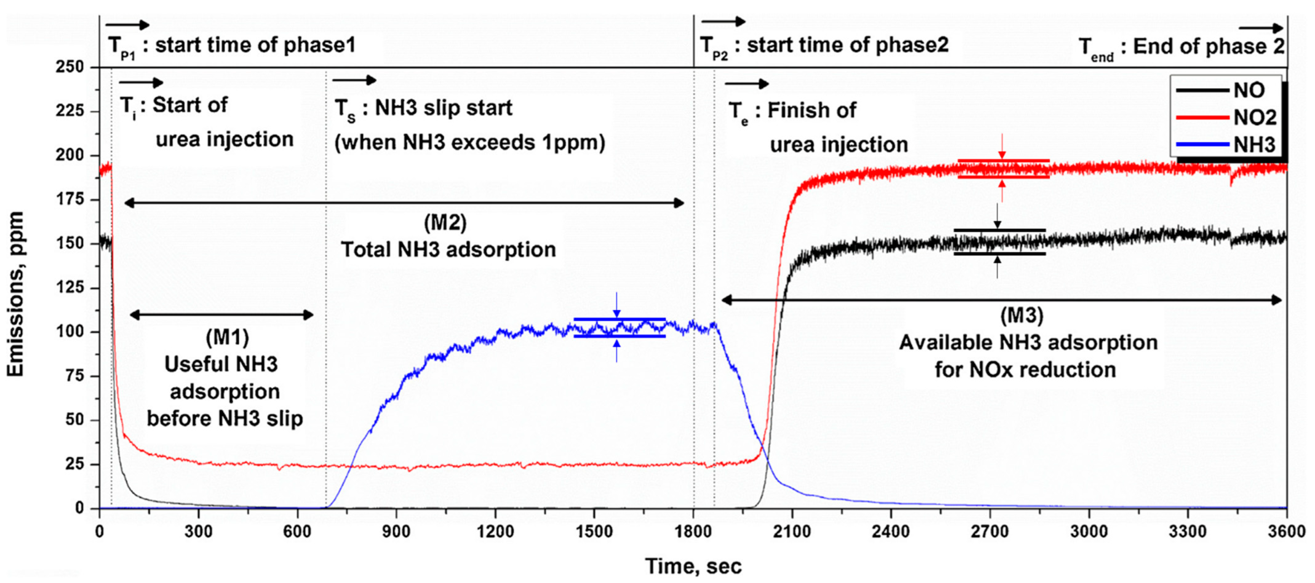
Figure 3.
NO and NO2 emission characteristics (a) after engine, (b) after DOC, and (c) after DPF.
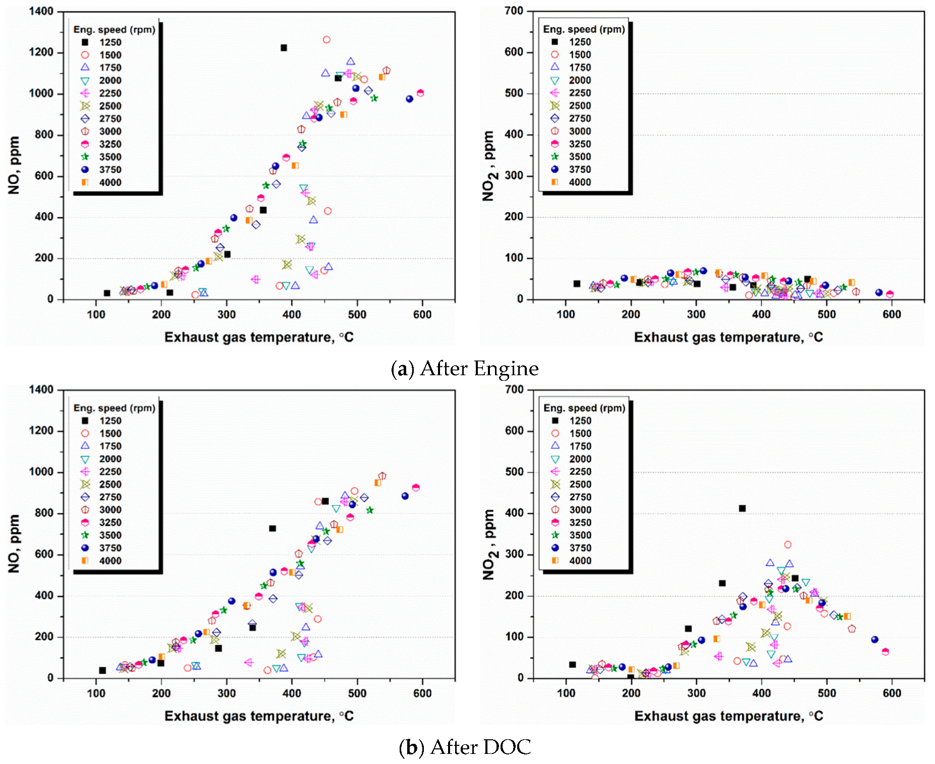
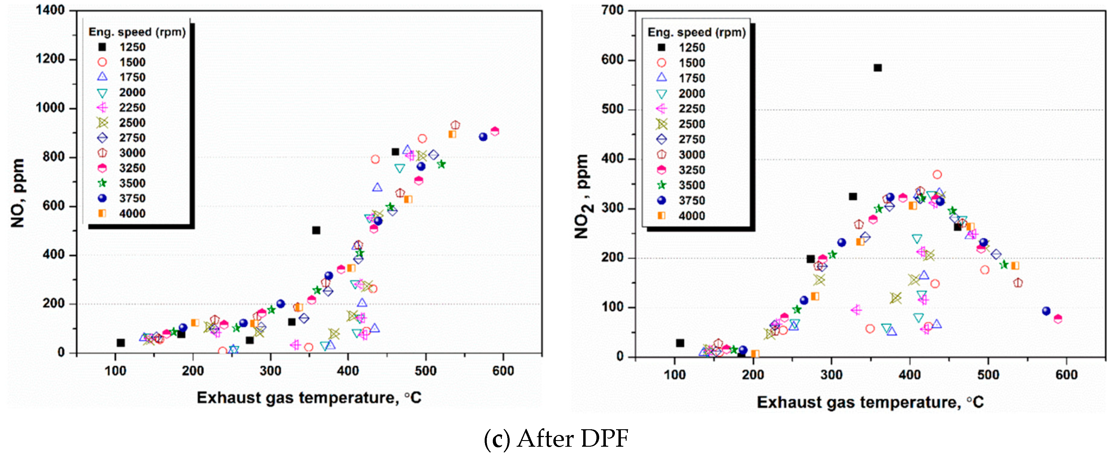
Figure 4.
NO and NO2 changes in DOC (a,b) and DPF (c,d).
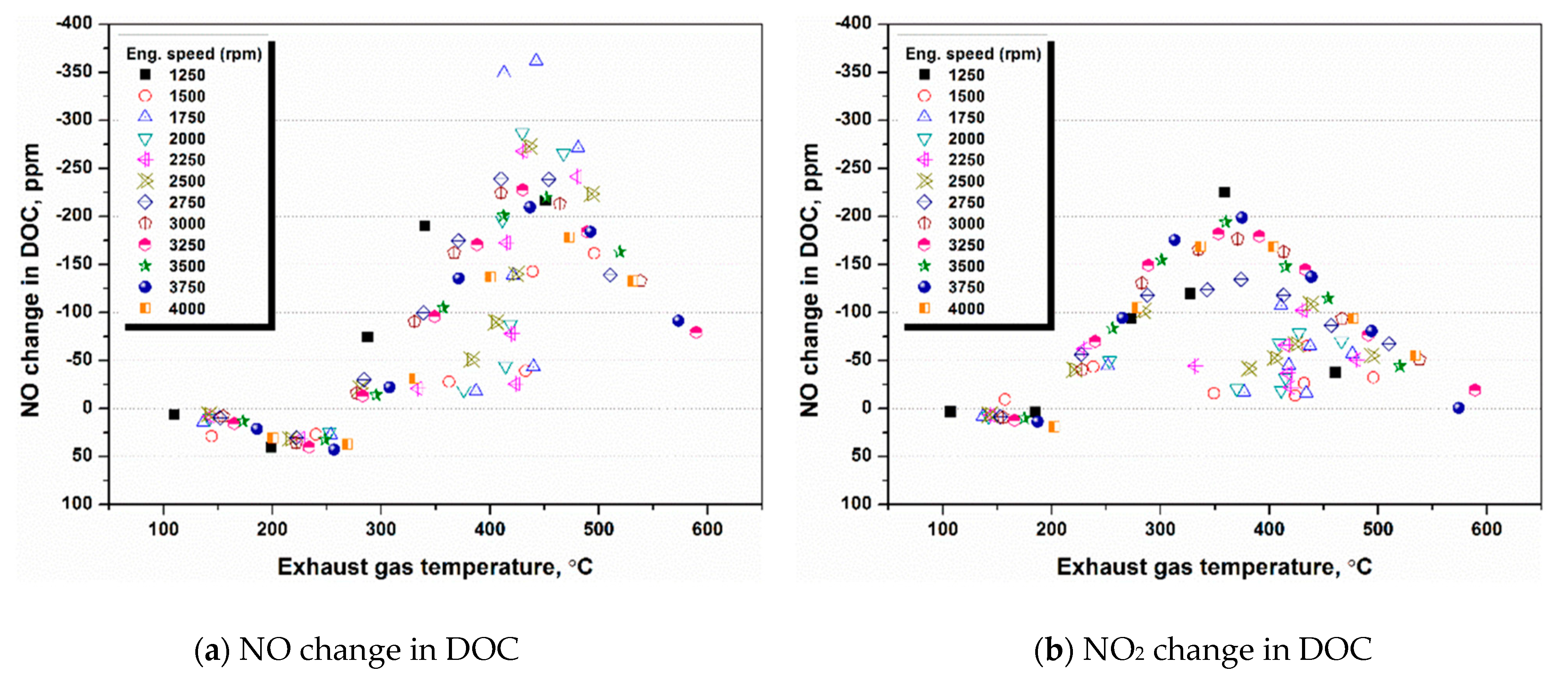
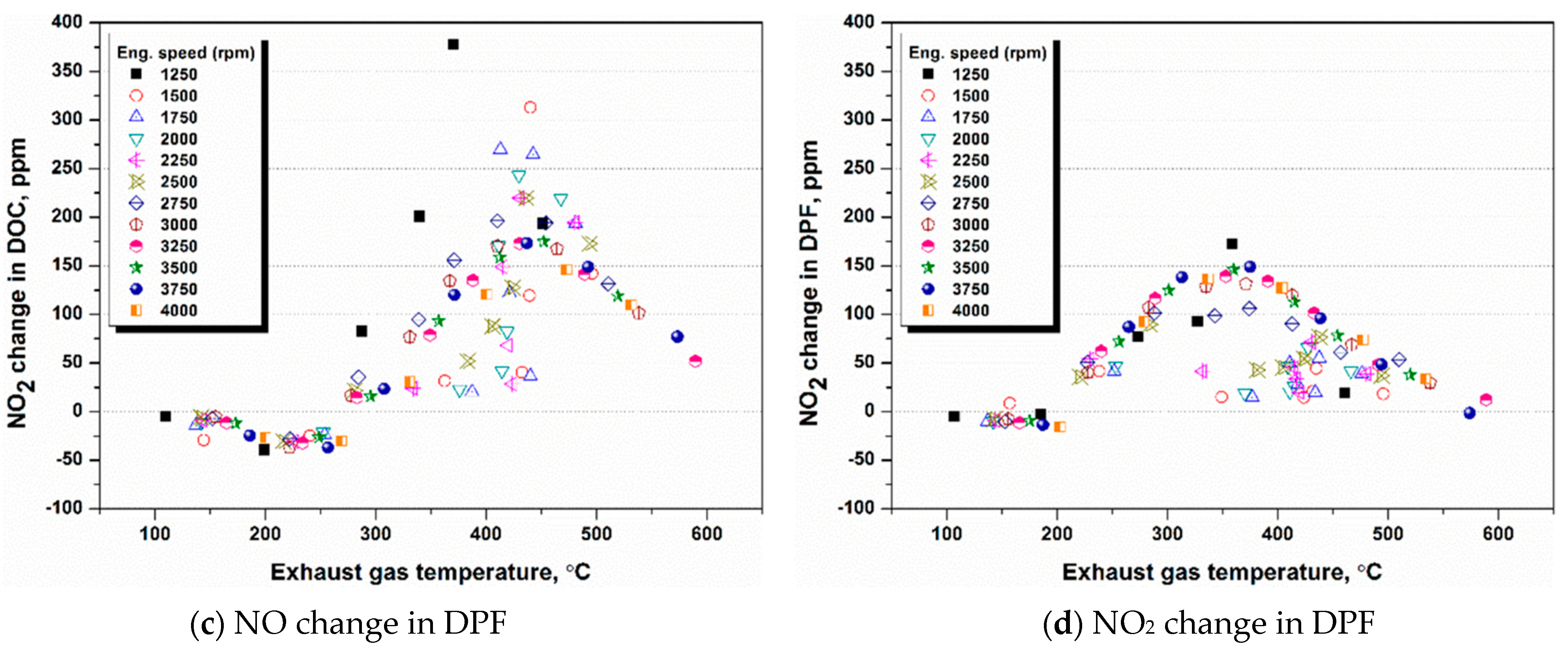
Figure 5.
Ratio of NO and NO2 according to the experimental conditions.
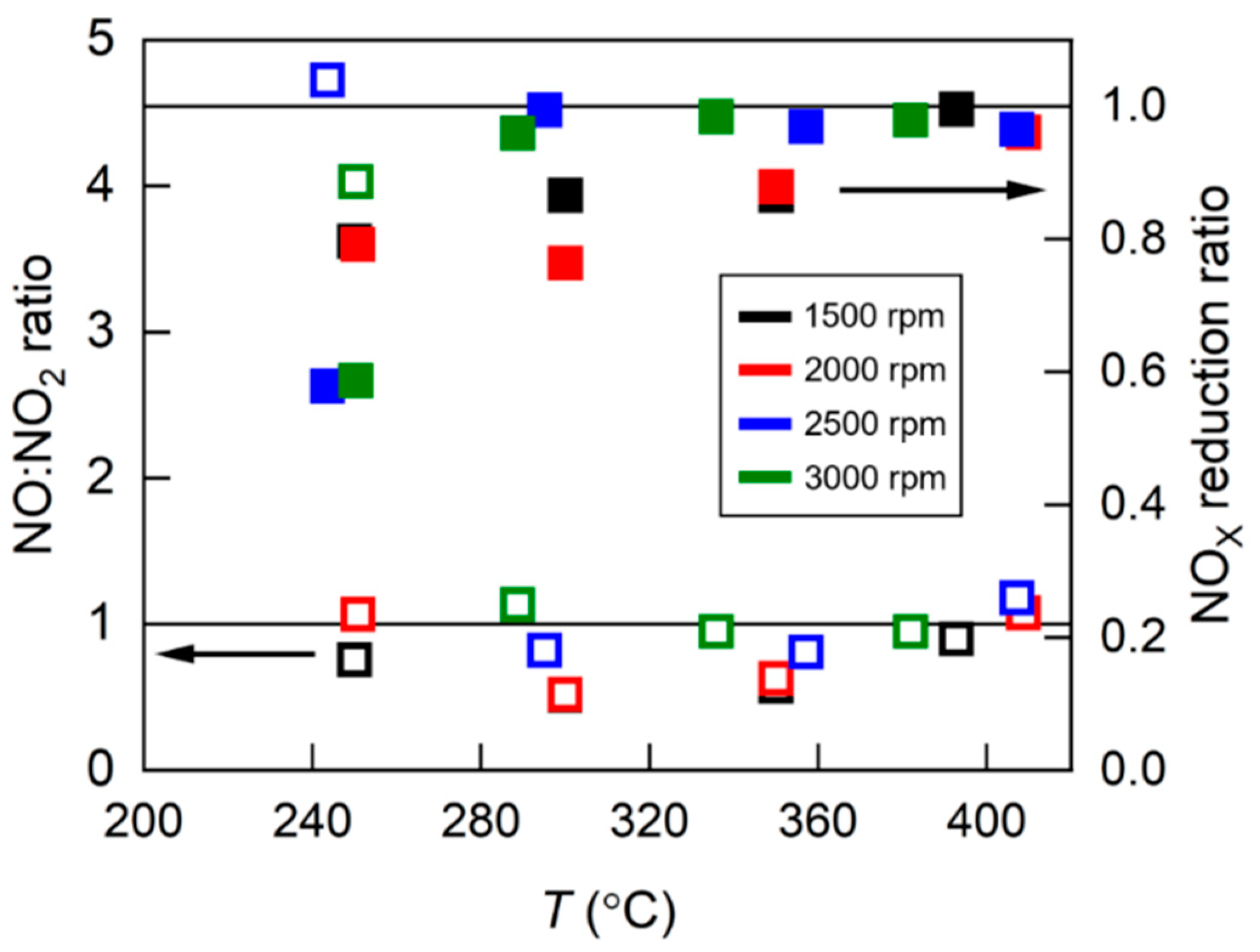
Figure 6.
NH3 storage amount calculated in Phase M1 according to experimental conditions.
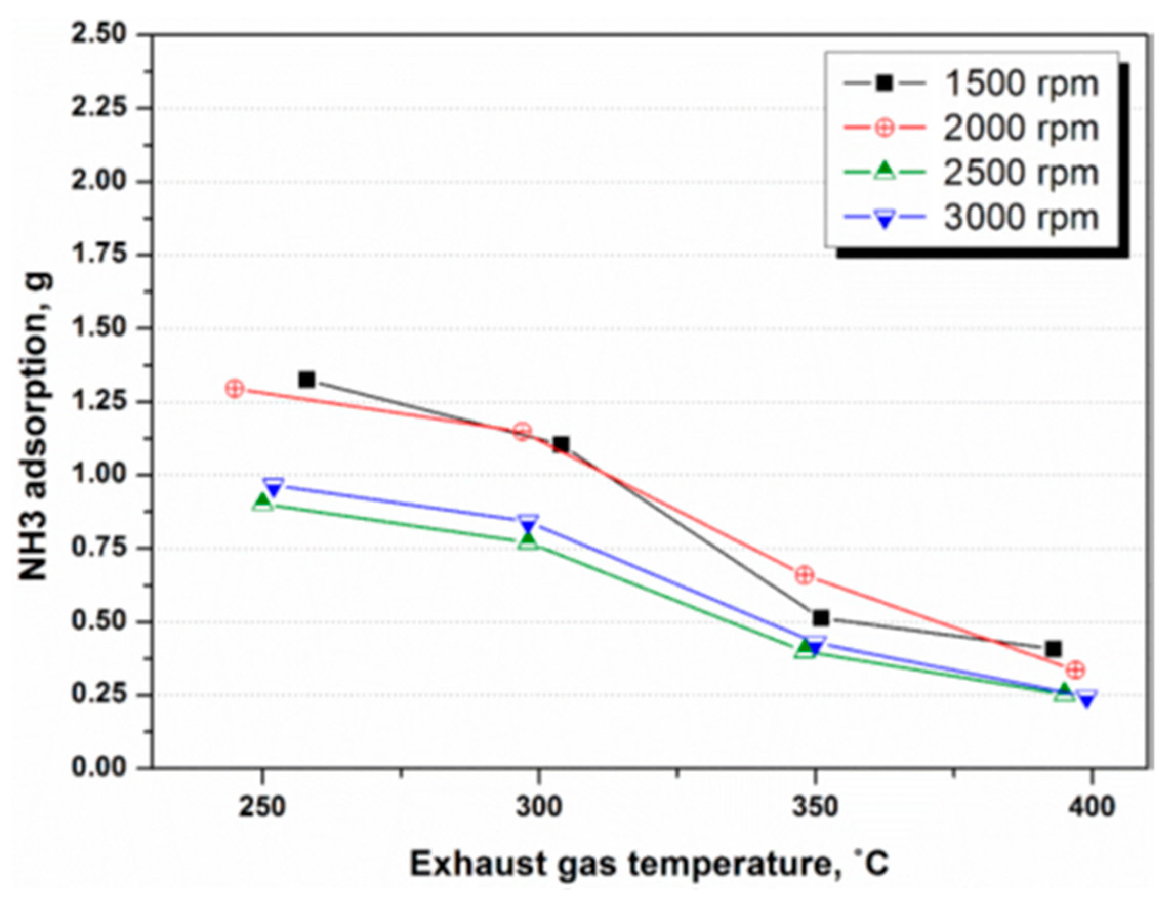
Figure 7.
NH3 storage amount calculated in Phase M2 according to experimental conditions.
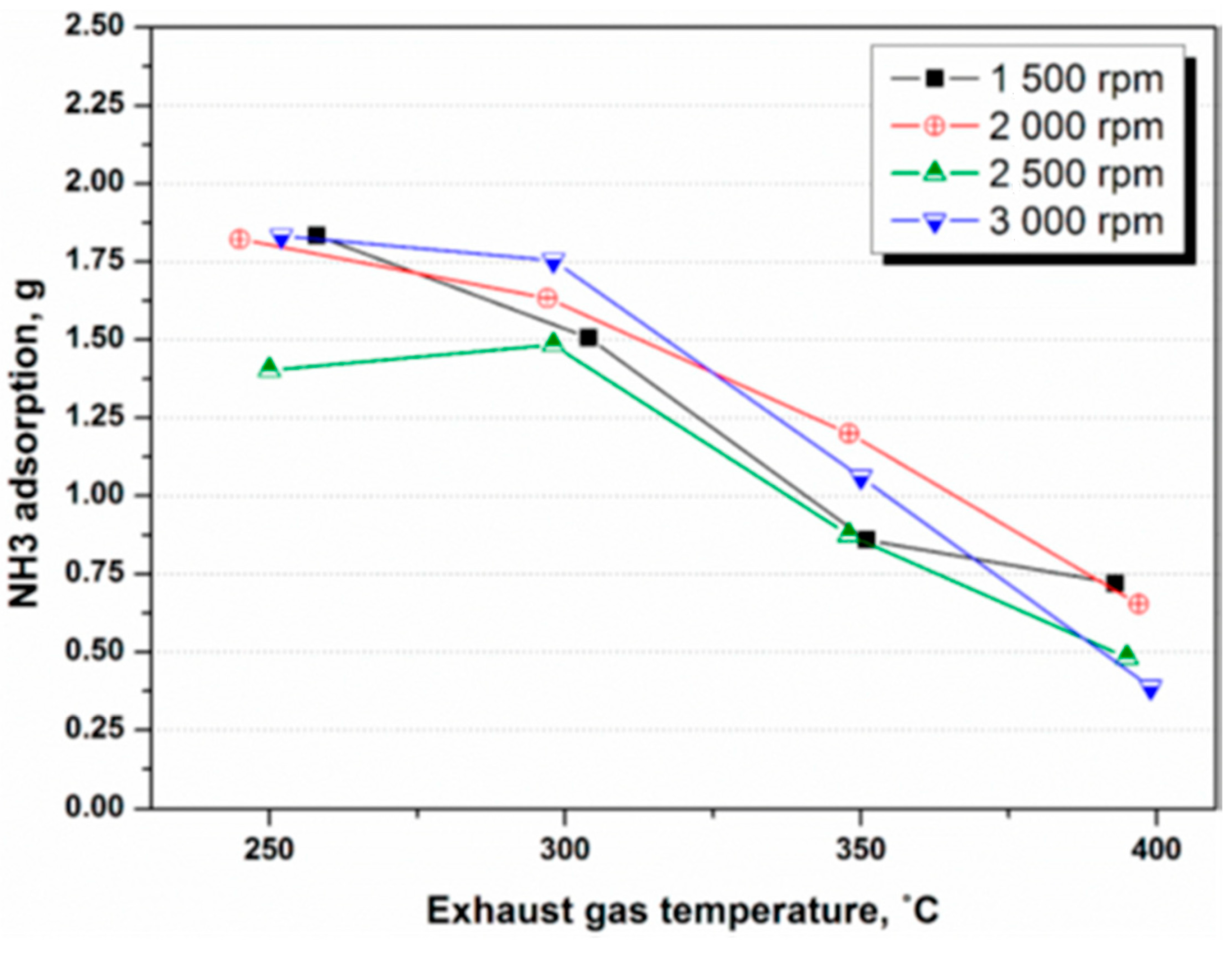
Figure 8.
NH3 storage amount calculated in Phase M3 according to experimental conditions.
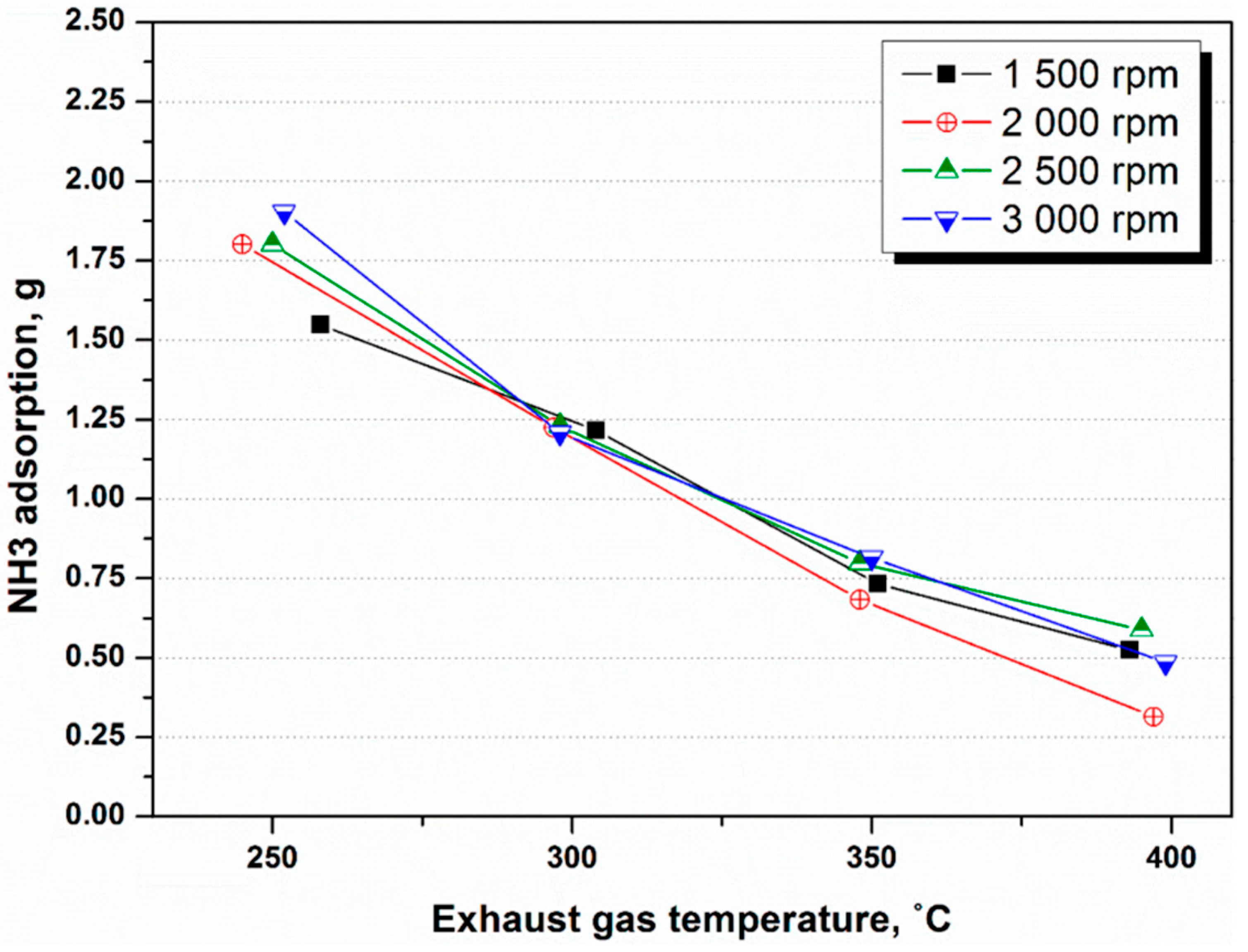
Figure 9.
Useful NH3 adsorption amount and ratio used for actual NOx reduction according to exhaust gas temperature.
Figure 9.
Useful NH3 adsorption amount and ratio used for actual NOx reduction according to exhaust gas temperature.
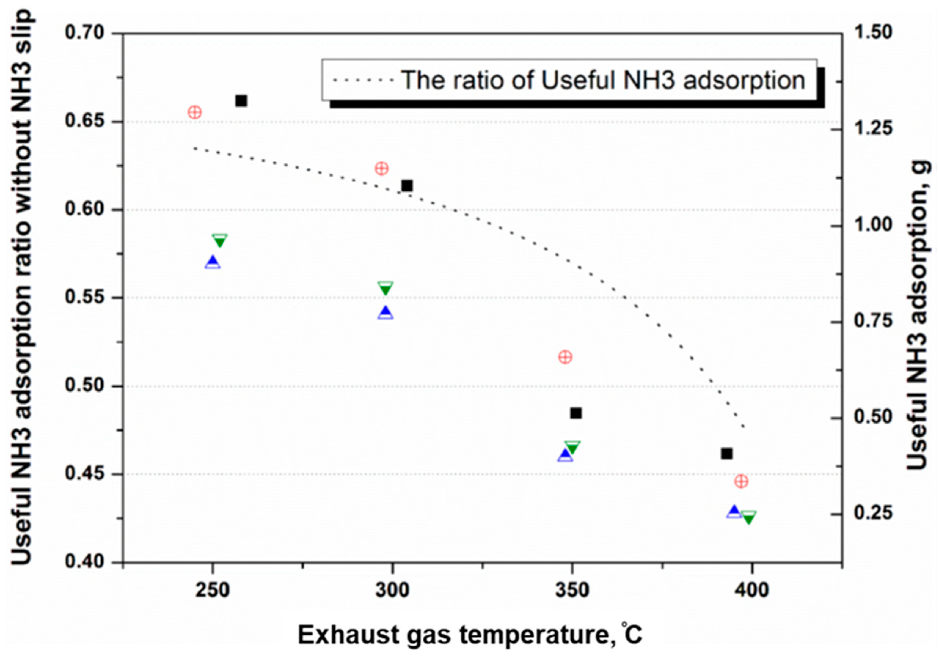
Figure 10.
Calculation of the NH3 adsorption rate and desorption rate (at 3000 rpm and 300 °C).
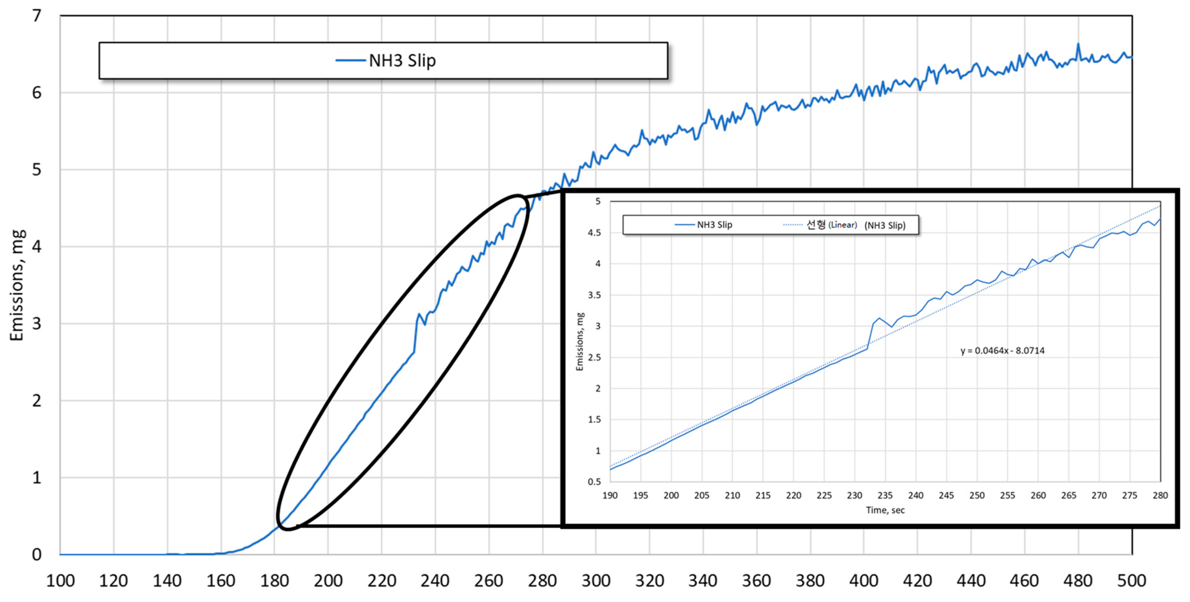
Figure 11.
Adsorption (a) and desorption (b) rates of NH3 in SCR in various conditions.

Figure 12.
Relative values of adsorption (a) and desorption (b) rates of NH3 in SCR in various conditions.
Figure 12.
Relative values of adsorption (a) and desorption (b) rates of NH3 in SCR in various conditions.


Table 1.
Diesel engine specifications.
| No. of Cylinders | 5 |
| Valve type | DOHC 20 valve |
| Strokes | 4 |
| Type | Turbo diesel |
| Rated power P (PS) | 186/4000 rpm |
| Rated torque M (Nm) | 418/1600–3000 |
| Experiment engine speed (rpm) | 1500, 2000, 2500, 3000 |
| Exhaust gas temperature (°C) | 250, 300, 350, 400 |
| Manufacture | 2006 |
| Emission standards | Euro 2 |
Table 2.
SCR system specifications.
| Category | DOC | DPF | SCR |
|---|---|---|---|
| Substrate | Cordierite | ||
| Catalyst | Pt + Promoter/TiO2 | V-W/TiO2 | |
| BPT | 285 °C | - | |
| Cell density | 400 cpsi | 300 cpsi | 400 cpsi |
| Diameter | 5.66 inch | 5.66 inch | 6.77 inch |
| Length | 4 inch | 10 inch | 10 inch |
Table 3.
Engine operating conditions under which the experiment was performed.
| Category | Engine Operating Conditions |
|---|---|
| Engine speed [rpm] | 1500, 2000, 2500, 3000 |
| Exhaust gas temperature [°C] | 250, 300, 350, 400 |
Disclaimer/Publisher’s Note: The statements, opinions and data contained in all publications are solely those of the individual author(s) and contributor(s) and not of MDPI and/or the editor(s). MDPI and/or the editor(s) disclaim responsibility for any injury to people or property resulting from any ideas, methods, instructions or products referred to in the content. |
© 2023 by the authors. Licensee MDPI, Basel, Switzerland. This article is an open access article distributed under the terms and conditions of the Creative Commons Attribution (CC BY) license (https://creativecommons.org/licenses/by/4.0/).
Share and Cite
MDPI and ACS Style
Jo, H.; Ko, A.; Jang, J.; Lim, O. Study on Rates of NH3 Adsorption and Desorption in SCR on Various Engine Operation Conditions. Sustainability 2023, 15, 14468. https://doi.org/10.3390/su151914468
AMA Style
Jo H, Ko A, Jang J, Lim O. Study on Rates of NH3 Adsorption and Desorption in SCR on Various Engine Operation Conditions. Sustainability. 2023; 15(19):14468. https://doi.org/10.3390/su151914468
Chicago/Turabian StyleJo, Hyun, Ahyun Ko, Jinyoung Jang, and Ocktaeck Lim. 2023. "Study on Rates of NH3 Adsorption and Desorption in SCR on Various Engine Operation Conditions" Sustainability 15, no. 19: 14468. https://doi.org/10.3390/su151914468
Note that from the first issue of 2016, this journal uses article numbers instead of page numbers. See further details here.