Article

Mechanical Behavior of a Novel Precast Concrete Beam–Column Joint Using the Mortise–Tenon Connection

School of Civil Engineering and Architecture, Wuhan Institute of Technology, Wuhan 430074, China
*
Author to whom correspondence should be addressed.
Sustainability 2023, 15(19), 14586; https://doi.org/10.3390/su151914586
Submission received: 20 July 2023 / Revised: 25 September 2023 / Accepted: 27 September 2023 / Published: 8 October 2023
(This article belongs to the Section Green Building)

Abstract

:
The construction industry has been a significant contributor to global carbon emissions. Fortunately, it is well known that precast concrete structures possess the benefit of reducing carbon emission, of which the beam–column joint plays a crucial role in resisting severe loads. Nowadays, the cast-in-place joint is mostly adopted for beam–column joint The authors declare no conflict of interests of precast concrete structures, and the building industrialization degree is insufficient. In light of this, a novel precast concrete beam–column joint using the mortise–tenon (MT) connection is proposed inspired by traditional timber structures, and the contrastive analysis of mechanical behaviors of this joint and the same-sized cast-in-place joint is conducted by the finite element method. The results indicate that the proposed MT joint has a better mechanical behavior by comparing with the corresponding cast-in-place joint as the beam–column joint. Meanwhile, the MT connection mode has the characteristics of standardized construction, in line with the concept of sustainable development, which can greatly save the construction period. This research demonstrates the feasibility of MT joints in traditional timber structures as beam–column joints in precast concrete structures, and the application of MT joints may be promoted if the size and shape of that are further optimized. Furthermore, this in turn helps research and innovation of precast building construction technology and promotes the sustainable development of the construction industry in the direction of energy conservation and environmental protection.

1. Introduction

In recent years, with the continuous improvement of the national economic level, the construction industry keeps the growing situation vigorous [1]. This rapid development has also contributed to the increase in carbon emissions, to be specific, the carbon emissions of the construction industry account for more than one third of global carbon emissions [2,3]. At present, countries around the world pay more and more attention to energy conservation and green economy, and the construction industry is gradually developing in the direction of energy conservation and emission reduction. As a new type of energy-saving and environmentally friendly building product, precast concrete frame structures have prominent advantages of standardization, factory, and environmental protection, which helps to achieve the purpose of carbon reduction extremely well to a great extent [4,5,6]. The prefabricated components of precast concrete structures are made in the closed space of the factory and only need to be transported to the site for assembly. This construction mode can greatly save the workload of on-site construction and effectively solve problems such as large resource consumption and serious pollution in traditional building construction. Therefore, precast concrete structures are in line with the development trend of the future construction industry, and governments are vigorously promoting the utilization of such structures, which have supremely broad prospects for development. It is worth pointing out that the beam–column joint is one of the crucial components of precast concrete frame structures [7,8]; thus, a novel type beam–column connection in precast concrete frame structures is proposed in this paper, and the mechanical behavior of that is investigated with sufficient emphasis.
Compared with the traditional cast-in-place structures, the precast concrete structures have achieved higher results in energy saving and emission reduction. However, the optimal design of the mechanical performance of the precast concrete structures has always been the most concerning problem for engineers and researchers, especially the beam–column joint. Therefore, relevant scholars around the world have carried out numerous research on joints of precast concrete structures in recent years. As a primary connection mode for traditional timber structures around the world, mortise–tenon (MT) connection is achieved by the exact match of concave and convex parts on the two members [9]. This connection method has a higher assembly mechanization construction degree, which can shorten the construction period, reduce the site workload and lower the energy consumption. This will help promote the application and promotion of intelligent construction and accelerate the transformation and upgrading of the traditional construction industry. Simultaneously, the excellent connection performance of this connection method has been demonstrated by many heritages [10,11]. Chun et al. [12] conducted an experimental study on several kinds of MT-connected beam–column frames under dynamic load. Ding et al. [13] evaluated the seismic performance of seven full-scale joints according to a two-series cyclic loading test program and revealed that the Design for Deconstruction with MT connection had a favorable seismic performance. Li et al. [14] proposed a detachable and replaceable non-destructive flat-steel jacket reinforcement method and confirmed that the initial stiffness and ultimate bearing capacity were improved markedly by the scale model test. Inspired by ancient MT connection, Feng et al. [15] proposed a novel joint for pultruded FRP beams and concrete-filled FRP columns and built an excellent accuracy predicted moment capacity as compared to the experimental results. Sun et al. [16] put forward that the MT joint could effectively reduce the slip displacement between hollow section square columns according to the results of finite element analysis. All these studies show that the MT joint has excellent mechanical properties.
Although the eminent mechanical performance of MT connection has been proved by multiple studies, it has not been widely utilized in precast concrete structures. This is because the manufacturing process of MT joint is prohibitively complicated and requires a high level of labor in earlier years, which greatly restricts practical engineering applications of such connection [17]. In terms of cost, the material cost for component fabrication of MT joint will be slightly higher than cast-in-place joint, but MT connection has the characteristics of standardized construction, in line with the concept of sustainable development, whose energy consumption is lower than that of cast-in-place method, which can greatly save the construction period. Therefore, the total cost of an MT joint is lower than a cast-in-place joint. Fortunately, the problem of the high manufacturing cost of MT joints can be effectively solved with the rapid development of computer manufacturing technology. Moreover, the rapid development of concrete 3D printing technology [18] provides a new idea for the precast concrete beam–column joint using the MT connection. This makes the MT joint with excellent mechanical performance once again an available option for joint connections.
Given this, a new type of beam–column joint using the MT connection is designed first based on a building frame structure, which includes the dovetail tenon and the straight tenon in two forms, and an outer steel jacket in the joint core area. In addition, the numerical simulation analyses of the proposed MT joint and the corresponding cast-in-place joint are carried out by ABAQUS finite element software (version 2020), and the superiority of the mechanical properties of this novel joint is verified. It will promote the application of MT joints in precast concrete structures and contribute to the green and sustainable development of the construction industry.

2. Methodology

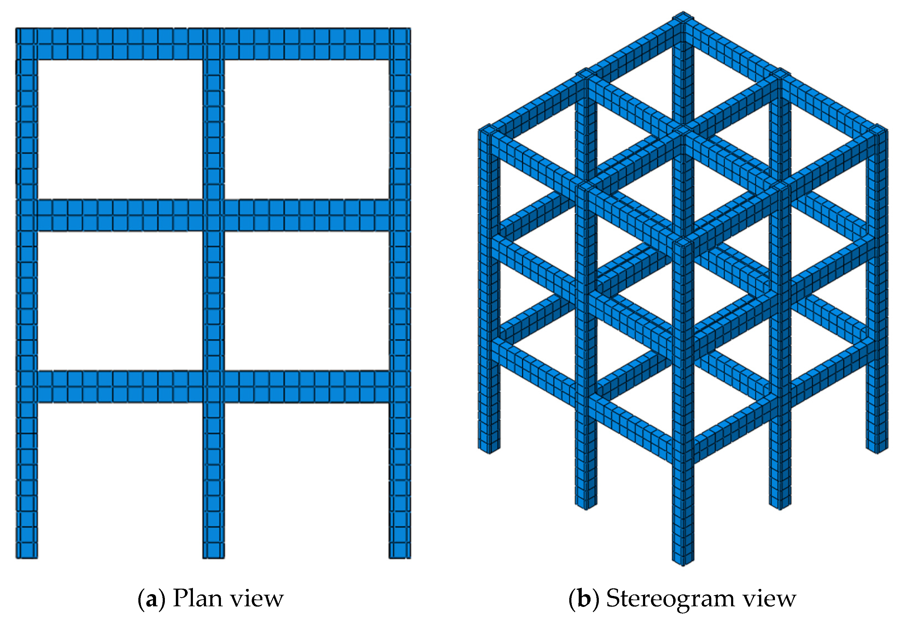
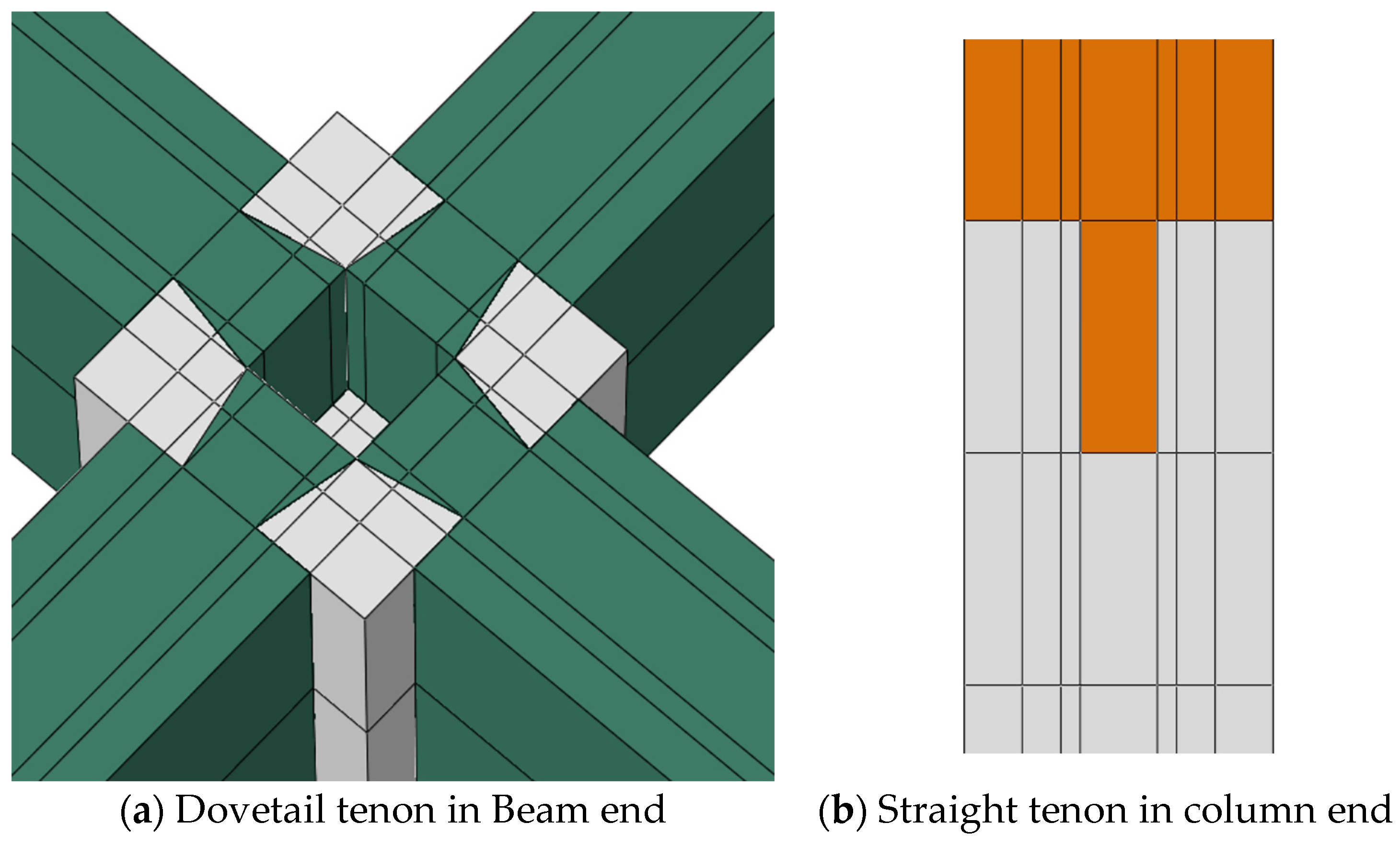
2.1. Scheme of MT Joint

A three-story two-span reinforced concrete frame structure is selected as the implementation case of this paper, whose exterior is shown in Figure 1, in which the height and span of the frame structure are 3.3 m and 3.6 m, respectively. According to the relevant provisions from the relevant design codes [19,20,21], the dimensions and reinforcement layout of the beam section and column section are shown in Figure 2. In addition, the Sustainability 15 14586 i0018@200 stirrup is arranged along the length of the beam and column, and the spacing of the stirrup encryption area is 100 mm. The thickness of the concrete protective layer is 20 mm. In terms of material, C35 and HRB400 are employed for the concrete and steel bars in the beams and columns, respectively.
The beam–column joints of the above structures are all cast in place, and a typical joint should be selected and designed as a MT joint in this paper. The shape and location of the joint to be investigated in this paper are determined by a simple mechanical analysis of the frame structure mentioned above. The horizontal loads F1, F2, and F3 are applied to the beam–column joint of each layer, respectively. Structure deformation and bending moment diagram are shown in Figure 3. The beam–column joint in the middle of the second layer of the frame structure is selected as the research object in the paper. The height of the column should be the distance of the reverse bending point of the column with adjacent layers, so the distance between the reverse bending points of the second and third layer columns in Figure 3b is the column height. Theoretically, the length of the beam ought to take the distance from the zero bending moment position of beams to the beam–column joint, but it is more difficult to pin down the zero bending moment position of the beams due to the influences of many factors. To simplify, the midspan of the beam is taken as the beam end of the selected joint.
The dimensions and material of the MT joint are consistent with those of the cast-in-place joint selected above. The primary member of the MT joint includes two connection forms, the dovetail mortise and the straight mortise. The prefabricated beam and the lower column are connected by the dovetail tenon, and the prefabricated upper and lower columns are connected by the straight tenon. To increase the stiffness of the joint core area, an outer steel sleeve is arranged in it. The outer steel sleeve is welded by angle steel, steel plate, and stiffener, of which material is Q235-B grade steel. The thickness of angle steel and steel plate is 6 mm, and the stiffener thickness is 25 mm. The length and width of the dovetail tenon are 125 mm and 150 mm, respectively, and the width of the narrowing tenon root is 100 mm. The height of the straight tenon at the end of the column is half the height of the beam. The specific design drawing is shown in Figure 4, Figure 5, Figure 6, Figure 7 and Figure 8.

2.2. Establishment of Numerical Model

The numerical models of the above MT joint and cast-in-place joint are established by ABAQUS software (version 2020). Both the outer steel sleeve and the concrete are simulated with 8-node C3D8R elements with hexahedral reducing integral, the C3D6 wedge elements are utilized in the oblique section, and the steel bar is simulated by T3D2 truss elements. The material parameters of each component adopted in the finite element model are indicated in Table 1 and Table 2. In order to meet the high computational efficiency and accuracy, the model is divided into hexahedral regional grids by structured grid partitioning technology, and the grids in the joint core area are encrypted. The grid division is shown in Figure 9, in which the outer steel sleeve and its adjacent concrete area are divided into an encrypted grid with a side length of 50 mm, and the remaining areas have a grid size of 100 mm. The steel bar is laid with 500 mm spacing and ensures that nodes only appear at the intersection. In addition, the plastic damage model is adopted in concrete constitutive relation, whose related parameters are shown in Table 3, and the common double broken line model is employed to describe the constitutive relationship of steel bars.
The MT joint involves contacts between multiple components, whose rationality in the model is critical to the accuracy of the results. The longitudinal reinforcement, stirrup, and structural reinforcement are merged into a steel cage first, and then the steel cage is embedded in the concrete, where the bond slip between the steel bar and concrete is ignored. In order to prevent the outer steel sleeve from penetrating the outside of the concrete, the normal contact between the two adopts hard contact that can transmit pressure, and the tangential contact takes advantage of a penalty function with a friction coefficient of 0.6, where limited slippage between contact surfaces is allowed. It is worth mentioning that the contact between the concrete beam and column adopts the cohesion–friction hybrid model as shown in Figure 10.
In the elastic stage, the interfacial shear stress only comes from the cohesion zone model, and the coulomb friction model does not work at this time, then the coulomb friction model begins to work if the cohesion zone model reaches the damage stage. The interfacial shear stress is provided by the two models at the same time from the damage to the complete degradation of the cohesion zone model. Subsequently, the coulomb friction model works separately when the cohesion zone model fails completely. In addition, the hard contact and penalty stiffness methods are adopted in the normal direction and tangential direction respectively, and the friction coefficient is 0.6 concerning the ACI 318-11 [22].
Because the torsion effect is not significant, only the forces in the plane of the nodes are considered to achieve the purpose of facilitating calculation. Below is the experimental device developed by the literature [23] and the schematic diagram is shown in Figure 11.
As shown in Figure 12, the base of the model column is set as a fixed hinge support, which can only be rotated around the X-axis. The loading mode includes the following two working conditions. Working condition I as shown in Figure 12a is the column end loading mode, which means the vertical axial force and horizontal tension are applied to the column end. Working condition II is the beam end loading mode; that is, the vertical axial force is applied to the column end connected to the beam and a reverse symmetric vertical load is applied to the left and right beam ends, as shown in Figure 12b. On the one hand, under this working condition I, only U1 and UR3 degrees of freedom are opened on the top of the column and the left and right beam ends of the joint, which limits the lateral displacement and lateral rotation. On the other hand, under working condition II, UR3 degree of freedom at the top of the joint column and U2 and UR3 degrees of freedom at the left and right beam ends are released, and the remaining displacements are restricted. In addition, the boundary conditions and loads are applied at four reference points on both ends of the beam and column of the model to prevent stress concentration.

3. Results and Discussion

The mechanical behaviors of MT and cast-in-place joints under the two working conditions are analyzed by using the above numerical models. In the first step, the axial force is applied to the top of the column according to the axial compression ratio of 0.2. The second step is to apply two load working conditions in the form of displacement, respectively, and simultaneously turn on the geometric nonlinear switch. Among them, in working condition I, the horizontal displacement in X direction is applied to the top of the column so that the right is positive direction. In working condition II, reverse symmetric vertical displacement is applied at both ends of the beam along the Y direction, with upward as positive and downward as negative. In this case, the left beam is subject to a negative bending moment and the right beam bears a positive bending moment.

3.1. Mechanical Properties of Joints under Working Condition I

First of all, working condition I is applied to the two types of members, whose tension and compression damage nephograms are shown in Figure 13 and Figure 14. Meanwhile, it needs to be explained that the initial damage value of the structure is 0, and it is in a critical state when the damage value reaches 1, and the structure fails when the damage value exceeds 1. Figure 13 gives the tension damage of the two types of connected members, and it shows that the tension damage distribution of cast-in-place and MT joints is similar, but the damage situation of the former is more serious than the latter, and there are many areas where the damage value is close to 1 in the cast-in-place joint. As can be seen from Figure 14, the compression damage of the cast-in-place joint is mainly concentrated in the core area of the node, and some areas are even about to reach the critical state of failure. However, the most remarkable compression damage of the MT joint is mainly concentrated in the column, which is away from the core of the node. Therefore, it can be preliminarily concluded that the damage resistance of the MT joint is better than that of the cast-in-place joint.
Yield is one of the important indexes to evaluate the bearing capacity of the structures, which is the state of the lowest stress value when the material begins to undergo obvious plastic deformation. The equivalent plastic strain (PEEQ) can reflect the corresponding stress state of the structure after plastic yield, and it also describes simultaneously the accumulation of structural plastic strain during loading. Figure 15 exhibits the nephogram of PEEQ in the two types of connected members under working condition I. It can be seen that the maximum PEEQ of the MT joint occurs in the middle position of the upper column, that is, the end of the outer steel sleeve. The PEEQ of cast-in-place joint is mainly concentrated near the core area of the joint, where the accumulation of plastic deformation is unfavorable to the stress of the structures. Compared with the cast-in-place joint, the plastic hinge of the MT joint shifts upward, which is more consistent with the structural design principle of “strong joints, weak components”. Furthermore, it is found that the obvious yield of partial concrete occurs in the joint core area of the cast-in-place joint by observing the central section of the equivalent plastic strain nephogram, whereas the core area of the MT joint does not yield.
The load–displacement curve is the main index to study the bearing capacity of a structure, which represents the correspondence between the real-time displacement of a certain part of the structure and the load. Figure 16 shows the change curve of displacement in two types of connected members with working condition I during the whole loading process. It can be seen from the load–displacement curve that both cast-in-place and MT joints have experienced four stress stages: elasticity, yield, strengthening, and failure. In the elastic stage, the slope of the MT joint is slightly smaller than that of the cast-in-place joint, which may be caused by the existence of unavoidable tiny gaps between the mortise and tenon. In the plastic stage, the curves of the two types of connection nodes are relatively flat, which indicates that the ductilities of the two types of nodes are commendable. Moreover, the yield load of the MT joint is about 20% larger than that of the cast-in-place joint, which further verifies the superiority of the MT joint.

3.2. Mechanical Properties of Joints under Working Condition II

The comparative analysis of the mechanical behavior of the MT and cast-in-place joints under working condition II is conducted in this section. Figure 17 and Figure 18 show the nephogram of tension damage and compression damage of MT and cast-in-place joints, respectively. As can be seen from Figure 17, the overall distribution of tension damage of MT and cast-in-place joints is similar, and the tension damage of left and right beams is central symmetry along the beam length, and the tension damage of the lower column is greater than that of the upper column because of the different boundary conditions of the bottom column and the top column. The tension damage distribution of the MT joint is similar to that of the cast-in-place joint, but the tension damage value of the MT joint is smaller than that of the cast-in-place joint. It can be seen from Figure 18 that the compression damage mainly concentrates on the column and joint core area, and the damage of the lower column is more obvious than that of the upper column. In the joint core area, the damage value of the cast-in-place joint is close to 1, which is significantly larger than that of the MT joint. Therefore, the performance of the MT joint is slightly better than the cast-in-place joint from the point of view of tension and compression damage.
As shown in Figure 19, the maximum PEEQ of the cast-in-place joint appears in the joint core area at the junction of the beam and column. In addition, it is found that the concrete inside has yielded through profile observation. Compared with the cast-in-place joint, the PEEQ value of the MT joint is overall smaller. Therefore, it is judged from the PEEQ value that the MT joint has a better bearing capacity than that of the cast-in-place joint.
Figure 20 shows the load–displacement curve comparison between MT and cast-in-place joints under working condition II. Among them, it is stipulated that the load and displacement of the beam end under positive bending moment are positive, and those are negative under negative bending moment. It can be seen from the load–displacement curve that the curve slopes of the two types of joints are slightly different in the elastic stage, which is similar to condition I. The yield load of the MT joint is greater than those of the cast-in-place joint, and the positive and negative bending moments exceed 38% and 19%, respectively.
In addition, it can be found that the descending section of the load–displacement curve of the MT joint under working condition I is more gentle than that under working condition II by comparing Figure 16 and Figure 20, which indicates that the ductility performance of the components under the two working conditions is different. This is mainly because the main force under working condition I is borne by the column end straight tenon in the joint core area, and the role of the straight tenon in the joint core area is equivalent to that of the concrete short column, which has good mechanical performance. Nevertheless, the dovetail tenon of the beam end is stressed greatly under working condition II, and the stress concentration effect at the edge of the dovetail tenon is more significant, resulting in a decrease in ductility.
In general, the mechanical behaviors of the new MT joint proposed in this paper are better than those of the cast-in-place joint under both working conditions, but the optimal structural form is worthy of further exploration. If more research on parameter optimization of this kind of joint is carried out, it will be really promoted and applied in a wider range, and then a greater contribution to the sustainable development of the construction industry can be made.

4. Conclusions

Inspired by the MT connection mode in traditional timber structures, a novel precast concrete beam–column joint using the MT connection is proposed in this paper, and the contrastive analysis of MT and cast-in-place connection is conducted based on the finite element results from ABAQUS software (version 2020). The following conclusions are drawn:
(1)
Compared with the cast-in-place joint, the tension and compression damage of the MT joint are smaller under the same working conditions. In addition, the MT joint is more consistent with the design principle of “strong joints, weak components”.
(2)
On the whole, the bearing capacity of the MT joint is higher than that of the cast-in-place joint. The ductility of the MT joint under the action of two working conditions is different, which is mainly caused by the difference in the main stress components at the column end of the joint core area under the two working conditions.
(3)
It is suggested to include the MT connection into the beam–column joint design in precast concrete structures. To make this kind of joint available on a large scale, more parameters involved in size and shape need to be optimized by numerical or experiment analysis, and then reliability analysis needs to be carried out to determine the best parameter design values. This will accelerate the improvement and optimization of precast concrete structures, and thus promote the green and sustainable development of the construction industry.
It is shown that the bearing capacity of the MT joint preliminarily is higher than that of the cast-in-place joint through static analysis, but the difference in dynamic properties between the two connect methods needs to be further inquired, and more valuable conclusions will be obtained by combining the shaking table test in the next phase of research.

Author Contributions

Conceptualization, Z.Z. and F.W.; methodology, J.H.; software, F.W.; validation, Z.Z., F.W. and J.H.; formal analysis, J.H.; investigation, Z.Z.; resources, Z.Z.; data curation, F.W.; writing—original draft preparation, F.W.; writing—review and editing, J.H.; visualization, J.H.; supervision, Z.Z.; project administration, Z.Z. All authors have read and agreed to the published version of the manuscript.

Funding

This research received no external funding.

Institutional Review Board Statement

Not applicable.

Informed Consent Statement

Not applicable.

Data Availability Statement

The data presented in this study are available on request from the corresponding author. The data are not publicly available due to privacy.

Conflicts of Interest

The authors declare no conflict of interest.

References

  1. Corney, S.R.; Puranam, A.Y.; Elwood, K.J.; Henry, R.S.; Bull, D. Seismic performance of precast hollow-core floors: Part 1-experimental data. Aci Struct. J. 2021, 118, 49–63. [Google Scholar] [CrossRef]
  2. Li, X.J.; Zheng, Y.D. Using LCA to research carbon footprint for precast concrete piles during the building construction stage: A China study. J. Clean. Prod. 2020, 245, 118754. [Google Scholar] [CrossRef]
  3. Mohebbi, G.; Hasan, A.; Blay-Armah, A.; Bahadori-Jahromi, A.; Mylona, A.; Barthorpe, M. Comparative analysis of the whole life carbon of three construction methods of a UK-based supermarket. Build. Serv. Eng. Res. Technol. 2023, 44, 355–375. [Google Scholar] [CrossRef]
  4. Lu, Z.; Wang, Z.; Li, J.; Huang, B. Studies on Seismic Performance of Precast Concrete Columns with Grouted Splice Sleeve. Appl. Sci. 2017, 7, 571. [Google Scholar] [CrossRef]
  5. Son, S.; Park, K.; Fitriani, H.; Kim, S. Embodied CO2 reduction effects of composite precast concrete frame for heavily loaded long-span logistics buildings. Sustainability 2021, 13, 1060. [Google Scholar] [CrossRef]
  6. Shi, X.; Rong, X.; Nan, L.; Wang, L.; Zhang, J. A new steel-joint precast concrete frame structure: The design, key construction techniques, and building energy efficiency. Buildings 2022, 12, 1974. [Google Scholar] [CrossRef]
  7. Zhang, Y.; Ma, W.; Li, X.; Li, K. Experimental research on seismic behavior of haunched concrete beam-column joint based on the bolt connection. Sustainability 2022, 14, 15644. [Google Scholar] [CrossRef]
  8. Abdelwahed, B. A review on reinforced concrete beam column joint: Codes, experimental studies, and modeling. J. Eng. Res. 2020, 8, 63–79. [Google Scholar] [CrossRef]
  9. Wu, G.; Zhong, Y.; Gong, Y.; Ren, H. Application of modern wood product glulam in timber frame with tenon- mortise joints and its structural behavior. J. Renew. Mater. 2019, 7, 451–461. [Google Scholar] [CrossRef]
  10. Liu, X.J.; Fu, X.N.; Guo, D.H.; Steinhardt, N.S. Chinese Architecture; Yale University Press: New Haven, CT, USA, 2002. [Google Scholar]
  11. Chen, Z.; Zhu, E.; Lam, F.; Pan, J. Structural performance of Dou-Gong brackets of Yingxian Wood Pagoda under vertical load-An experimental study. Eng. Struct. 2015, 80, 274–288. [Google Scholar] [CrossRef]
  12. Chun, Q.; Yue, Z.; Pan, J.W. Experimental study on seismic characteristics of typical mortise-tenon joints of Chinese southern traditional timber frame buildings. Sci. China Technol. Sci. 2011, 54, 2404–2411. [Google Scholar] [CrossRef]
  13. Ding, T.; Xiao, J.; Chen, E.; Khan, A.-U. Experimental study of the seismic performance of concrete beam-column frame joints with DFD connections. J. Struct. Eng. 2021, 24, 1709–1723. [Google Scholar] [CrossRef]
  14. Li, H.M.; Qiu, H.X.; Wang, W.B. Experimental study on the mechanical performance of mortise-tenon joints reinforced with replaceable flat-steel jackets. J. Renew. Mater. 2021, 9, 1110–1125. [Google Scholar]
  15. Feng, P.; Li, Z.; Wang, J.; Liu, T.Q. Novel joint for pultruded FRP beams and concrete-filled FRP columns: Conceptual and experimental investigations. Compos. Struct. 2022, 287, 115339. [Google Scholar] [CrossRef]
  16. Sun, L.; Liang, Z.; Cai, M.; Liu, C.; Wang, P.; Liu, M.; Liu, F. Seismic behaviour of TSOBs bolted I-beam to hollow section square column connection with inner stiffener. J. Build. Eng. 2022, 51, 104260. [Google Scholar] [CrossRef]
  17. Crayssac, E.; Song, X.; Wu, Y.; Li, K. Lateral performance of mortise-tenon jointed traditional timber frames with wood panel infill. Eng. Struct. 2018, 161, 223–230. [Google Scholar] [CrossRef]
  18. Lyu, F.; Zhao, D.; Hou, X.; Sun, L.; Zhang, Q. Overview of the development of 3D-printing concrete: A review. Appl. Sci. 2021, 11, 9822. [Google Scholar] [CrossRef]
  19. GB 50010-2020; Code for Design of Concrete Structures. China Architecture & Building Press: Beijing, China, 2010.
  20. GB 50009-2012; Load Code for the Design of Building Structures. China Architecture & Building Press: Beijing, China, 2012.
  21. GB 50011-2010; Code for Seismic Design of Buildings. China Architecture & Building Press: Beijing, China, 2010.
  22. ACI 318-11/ACI 318R-11; Building Code Requirements for Structural Concrete and Commentary. American Concrete Institute: Farmington Hills, MI, USA, 2011.
  23. He, R.; Wang, J.; Hu, Z.; Liu, S.; Li, H. Experimental and theoretical analysis of flexural performance of U-shaped steel-concrete composite beams covered by tenon and mortise steel structure. Build. Struct. 2022, 52, 80–87. [Google Scholar]
Figure 1. Structural representation.
Sustainability 15 14586 g001
Figure 2. Dimensions and reinforcement of beam and column section.
Sustainability 15 14586 g002
Figure 3. Deformation and bending of the structure.
Sustainability 15 14586 g003
Figure 4. Design parameters of joints.
Sustainability 15 14586 g004
Figure 5. Design parameters of outer steel sleeve.
Sustainability 15 14586 g005
Figure 6. Design parameters of the beam with MT joint.
Sustainability 15 14586 g006
Figure 7. Design parameters of beam with MT joint.
Sustainability 15 14586 g007
Figure 8. MT joint in stereogram view.
Sustainability 15 14586 g008
Figure 9. Grid division diagram.
Sustainability 15 14586 g009
Figure 10. Cohesion–friction hybrid model.
Sustainability 15 14586 g010
Figure 11. Test device diagram.
Sustainability 15 14586 g011
Figure 12. Diagram of model loads and boundary conditions.
Sustainability 15 14586 g012
Figure 13. Nephogram of tension damage under working condition Ⅰ.
Sustainability 15 14586 g013
Figure 14. Nephogram of compression damage under working condition Ⅰ.
Sustainability 15 14586 g014
Figure 15. Nephogram of PEEQ under working condition Ⅰ.
Sustainability 15 14586 g015
Figure 16. Load–displacement curve under working condition Ⅰ.
Sustainability 15 14586 g016
Figure 17. Nephogram of tension damage under working condition II.
Sustainability 15 14586 g017
Figure 18. Nephogram of compression damage under working condition II.
Sustainability 15 14586 g018
Figure 19. Nephogram of PEEQ under working condition II.
Sustainability 15 14586 g019
Figure 20. Load–displacement curve under working condition II.
Sustainability 15 14586 g020
Table 1. Material parameters of the concrete.
Strength ClassElasticity Modulus (MPa)Poisson RatioDensity (kg/m3) f ck (MPa) f tk (MPa)
C3531,3340.2240023.42.2
Table 2. Material parameters of the steel.
TypeDensity
(kg/m3)
Elasticity Modulus
(MPa)
Poisson RatioYield Strength
(MPa)
Ultimate Strength
(MPa)
steel bar7850200,0000.3400540
outer steel sleeve
(Q235-B)
7850210,0000.3235375
Table 3. Parameters of the concrete constitutive model.
Expansion AngleEccentricity Ratio f b 0 / f c 0 K Viscosity Coefficient
30°0.11.160.66670.005
Disclaimer/Publisher’s Note: The statements, opinions and data contained in all publications are solely those of the individual author(s) and contributor(s) and not of MDPI and/or the editor(s). MDPI and/or the editor(s) disclaim responsibility for any injury to people or property resulting from any ideas, methods, instructions or products referred to in the content.

