Abstract
Highly radioactive materials classified as high-level nuclear waste (HLW) of atomic power engineering should be disposed of deeply underground in special geological disposal facilities (GDFs), which can be of either shaft or borehole type. The advantages of borehole-type GDFs result from smaller volumes of mining operations, a simpler construction technology, shorter construction time and cost. This allows us to consider them as an alternative to shaft-type GDFs. The parts of the boreholes in which waste containers should be placed can be both vertical and horizontal. Computer simulation of the migration of radionuclides from a group of parallel horizontal boreholes into the biosphere made it possible to conclude that horizontal GDF boreholes have significant advantages over vertical ones. We determined a forecast of 241Am migration by a method of mathematical modelling of 241Am release from vitrified HLW disposed of in several horizontal drillholes. The maximum concentrations of americium in the near-surface groundwater above the repository are calculated depending on the number of boreholes, the depth of their location and the distance between them, the permeability of rocks and the time of waste storage prior to disposal. Influence of different conditions on the safety of a GDF of borehole type is estimated. Calculations show that the heat generated by HLW causes a weaker groundwater convection near horizontal boreholes compared to vertical boreholes of the same capacity. In addition to that, at an equal thickness of the rock layer separating the HLW from the surface, the geothermal temperature of the host rocks in the near field of a horizontal borehole will be lower than the average geothermal temperature near a vertical borehole. As a result, the rate of radionuclides leaching from the waste forms by groundwaters will also be lower in the case of horizontal boreholes.
1. Introduction
The growing demand of the global economy for energy requires a sustainable development of nuclear power engineering (NPE), at least for the next several decades. In the open nuclear fuel cycle of NPE, spent nuclear fuel (SNF) is unloaded from reactors and considered as a waste, whereas in a closed cycle, the SNF is reprocessed to extract actinides and make new fuel. Processing of 1 tonne of SNF typically produces 13–34 m3 of highly radioactive liquid with a specific activity of more than 3.7 × 10¹⁰ Bq/L considered as high-level radioactive waste (HLW) [1]. The long-term environmental hazard of SNF and HLW is determined by long-lived actinides and fission products with half-lives ranging from hundreds to millions of years. The best way to isolate them reliably from the biosphere is their placement in geological disposal facilities (GDF) located within crystalline rocks, salts, clays, or shales [2,3,4,5]. Prior to disposal, the liquid HLW passes through a number of predisposal steps [2], being currently solidified into vitreous matrices of B-Si or Al-P composition [6,7,8,9,10,11]. The HLW disposal facilities in deep geological formations can be of shaft or borehole type. In the GDF shaft version, at a depth of about 0.5 km, a system of workings is created to accommodate waste containers. The design capacity of shaft-type GDF varies from 5300 to 108,000 tonnes for SNF and from 1000 to 7000 m3 for vitrified HLW [3]. In the case of joint disposal of high-level and intermediate-level waste with long-lived radionuclides, as in France or Russia, their volume in the GDF can reach 150,000 m3 [10]. The cost of shaft GDF construction is from 2 to 15 billion US dollars, the time from searching for a site to obtain a license for its creation takes 30–50 years, and the same interval is used to estimate the time for placing HLW and subsequent closure of the GDF [5].
Borehole disposal is a less costly and time-consuming alternative to shaft-type disposal options. It is proposed to use boreholes for relatively small volumes of HLW enclosed in thick-walled containers, for example, for disused sealed radioactive sources [12,13]. SNF and HLW are proposed to be disposed of in boreholes with a diameter of 0.2–0.8 m at a depth of up to 5 km, where the lower part with waste is from 1 to 3 km. This disposal option has been known for more than 65 years [14]; this concept has been repeatedly refined [15,16,17,18,19,20,21,22,23,24,25,26,27], although it has been noted [12,13,23,24,25] that borehole disposal facilities cannot solely be used for the disposal of the entire range of HLW and SNF accumulated.
In recent years, much attention has been paid to vertical boreholes with a horizontal termination at depths from 1 to 2 km [28,29,30,31,32,33,34]. The drilling of such boreholes has long been carried out in the exploration and production of hydrocarbons [35]. There are several projects in the world on the possible use of deep boreholes with horizontal terminations for the purpose of SNF and HLW disposal [36,37]. Such disposal facilities are also considered in countries with a low share of nuclear power in the energy balance and a small inventory of nuclear waste, such as Denmark, Norway, Croatia, Slovenia and the Netherlands [36,38]. Nuclear waste management organizations of Slovenia and Croatia signed a contract with the private company Deep Isolation (Berkeley, CA, USA) to estimate the cost of SNF and HLW disposal in vertical and horizontal boreholes located in crystalline rocks and shales [39].
Disposal projects provide for the possibility of retrieving SNF and HLW from the GDFs [40] in the event of an emergency loading of waste into a borehole and of a spread of radioactive contamination, as well as in connection with the emergence of better methods for isolating nuclear waste or potential discovery of usefulness of HLW and SNF in the future. The complexity of waste retrieval was considered as one of the disadvantages of borehole GDFs [19,20,21]; thus, preference is given to shaft-type GDFs in national nuclear waste management programmes [3], from which, if necessary, it is easier to remove waste containers.
To retrieve containers with HLW from boreholes, it is proposed to use devices developed in the oil and gas industry [35,37], and this disadvantage of the borehole GDF has lost its significance. In the case of a horizontal borehole, containers with HLW are placed under a layer of low permeable rocks [28,29,30,31,32,33,34]. HLW container loading is carried out through the vertical part of the borehole, which is connected to its horizontal part by a section of a large radius of curvature for the promotion of containers. Many works [26,33,34,37] note the advantages of borehole GDFs for HLW and SNF compared to shaft- type GDFs:
- Long-term safety due to the large depth of disposal;
- Economical access to rocks with high insulating properties;
- Weaker requirements for the infrastructure of a borehole GDF and a much smaller area of ground facilities (footprint);
- Significantly shorter time for the construction of a borehole GDF and loading of HLW and its significantly lower cost;
- Possibility of creating a borehole GDF in close proximity of the place of waste production;
- Extremely low probability of unauthorized access to radioactive materials;
- Minimal control after completion of disposal campaign and sealing of the GDF;
- High salinity hinders the development of convection of underground waters due to the heat release of SNF and HLW;
- Waste isolation is facilitated by the low solubility of actinides under reducing conditions.
The GDF long-term safety is determined by the inventory of radionuclides that will be released from the repository into the biosphere. It can be estimated by modelling the migration of radionuclides [27,31,32,33,34,35,36,37,38,39,40,41,42]. Disposal of waste in horizontal boreholes has a number of advantages over disposal in vertical boreholes of the same length. When HLW is disposed of in deep boreholes, due to the weak regional flow of water, convection, caused by the heat generation in the waste, will play an important role in the transfer of contaminations. The driving forces of thermal convection depend on the vertical extent of the range of heated rocks. For a vertical borehole, this is the length of that part where containers with HLW are located, and in the case of horizontal boreholes, it is of the order of their diameter. Hence, the rate of thermal convection of water for waste packages located in horizontal boreholes will be much less than in the case of vertical boreholes. Another factor is the growth of rock temperature with depth due to the geothermal gradient: with an average value of 0.025 K/m, the temperature at a depth of 5 km will be about 125 °C. The intensity of radionuclides leaching from HLW alumino-phosphate (Al-P) and boro-silicate (B-Si) glass matrices by aqueous solutions increases with temperature [8,43,44]. Given the possible temperature regimes in deep boreholes [29,45], this can cause a severe radioactive pollution in the near field of the borehole GDFs. Therefore, to assess the reliability of HLW isolation in the borehole, it is necessary to consider the migration of radionuclides due to thermal convection of groundwater. From the viewpoint of rational use of the allotment area, it is worthwhile to dispose HLW in a group of boreholes, as is shown in Figure 1. Assessments of radionuclides release from such a repository to the biosphere can be obtained only from a forecast of radionuclides migration obtained by methods of mathematical modeling. Such studies were absent until now. The objective of our work is modeling of radionuclides migration from a group of horizontal boreholes loaded with solid HLW to the Earth’s surface.
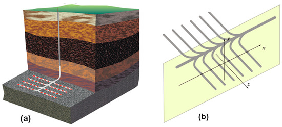
Figure 1.
Placement of containers in a group of parallel horizontal boreholes: (a) extending from one vertical borehole and (b) a vertical section of the GDF, perpendicular to the horizontal boreholes with waste. Red dashes denote containers with HLW.
2. Methods
Migration of radionuclides from the borehole GDF to the Earth’s surface was studied by mathematical modelling with use of numerical simulation methods.
To increase the volume of HLW, not one but several boreholes with a length of 2–3 km, extending from a common vertical access borehole, are of interest (Figure 1a) where we consider a vertical plane perpendicular to the waste disposal areas and introduce for analysis a Cartesian coordinate system (Figure 1b).
Outside the ends of the parallel horizontal boreholes, the distributions of temperatures and concentrations of radionuclides that entered the groundwater during the leaching of matrices are invariant by translation along the axis z. Therefore, heat transfer in rocks, the development of thermal convection of groundwater and the migration of radionuclides can be considered in a two-dimensional approximation in the x-y plane. Although this model is applicable for any number of wells, the case when the GDF system consists of 6 wells is presented as an example of calculation (Figure 2).
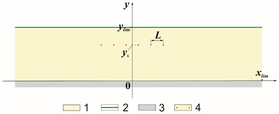
Figure 2.
Two-dimensional modellig area. (1) Rocks containing the GDF; (2) Earth’s surface; (3) underlying low-permeability rocks; (4) positions of horizontal boreholes with HLW.
The borehole system is symmetric about the axis passing through the middle of the segment connecting the centres of the outermost boreholes. Therefore, to model the spread of radioactive contamination from the GDF, it is sufficient to consider the processes of convection, heat transfer and radionuclide transfer not in the entire area of the rock mass (), but in the half-band .
Water filtration rates satisfy Darcy’s law [46]:
where are groundwater filtration rate components; is rock permeability; is dynamic viscosity of groundwater; is pressure; is temperature-dependent water density; is acceleration of gravity. We simulated the thermal convection of the groundwater with use of Boussinesq’s approximation [47], according to which all properties of the liquid are assumed to be constant, with the exception of density in the expression for gravity force. In this case, the filtration rate components satisfy the continuity equation in the form [46]
Substituting the expressions for the filtration rate components (1) into (2), we obtain
We will assume permeability of the rock massif is uniform, the density of groundwater does not depend on pressure and its dependence on temperature can be approximated by a linear function , where is temperature in centigrade; is the coefficient of thermal expansion of water; and are approximation constants.
Then Equation (3) takes the form
The temperature distribution satisfies the equation of transient convective heat transfer [46]:
where is time; are, respectively, density, specific heat capacity and thermal conductivity of the solid phase (waste, rocks); is specific heat capacity of water; is heat generation rate per unit volume, , if there is such a number for which the inequality is satisfied. Here is heat generation rate per unit volume of HLW; is the coordinate of the center of the i-th borehole; is waste block radius; is number of boreholes. The value of is determined by the initial composition of the waste and the duration of their holding in temporary storage before disposal. The calculation method is described in detail in the work [42]. The transfer of radionuclides by water is governed by the mass transfer equation in a porous medium in approximation of the advection–dispersion model [46].
where is radionuclide concentration in water; is solid-phase porosity; is the coefficient of radionuclide distribution between water and solid phase; is the radioactive decay constant of the radionuclide; are components of the dispersion tensor, determined by the formulas
Here are coefficients of longitudinal and transverse dispersion in a porous medium.
The molecular diffusion coefficient in a porous medium is defined as , where is the coefficient of molecular diffusion of the radionuclide in water; is a coefficient depending on the curvature of filtration channels in a porous medium (). The mass of the radionuclide entering a unit volume of groundwater per unit time is denoted as ; obviously, outside the borehole, = 0. If the condition is satisfied for some , then
where is mass fraction of the radionuclide in the waste form when loaded into the GDF; and is leaching rate of the waste form. According to Arrhenius’ formula,
where , are constant coefficients; is the activation energy; is the gas constant.
The expression (7) is in a good agreement with the experimental data on the leaching of borosilicate glasses with water [8] with the coefficients = 1.47 and = −6950 (if is expressed in kg/(m2 s)). During leaching, the radius of the waste block decreases:
where is density of the waste form.
Taking into account the mirror symmetry of the system about the y axis and the low permeability of the underlying rocks, the boundary conditions for Equation (4) can be written as
where is atmospheric pressure.
The boundary and initial conditions for Equations (5) and (6) take the form
To visualize two-dimensional flows, it is convenient to use streamlines. Since Equation (2) is satisfied, we can introduce a stream function such that
In this case, the Equation (2) is satisfied automatically.
Let us rewrite Equation (1) in the form
Let us differentiate the first of Equation (11) with respect to y, the second with respect to x and subtract one from the other. Substituting into the resulting equation of expression (10) the velocity component through the stream function, we obtain
Hence, with constant and and a linearized dependence of density on temperature, we obtain
Since the impermeability conditions are set on the lower and side boundaries of the region, the zero Dirichlet conditions are valid for the stream function on these boundaries. To define completely the boundary problem for Equation (12), it remains to set the boundary condition at , i.e., at the top of the modelling domain. Solving the boundary problem (4)–(8) and finding , we can determine :
Since is known from the solution of problem (4)–(8), it is possible to calculate the values of the integral on the right-hand side of (13). Thus, for Equation (12), boundary conditions are specified in the form
When choosing methods for solving boundary value problems (4)–(8), (12)–(14) and integrating transport Equations (5) and (6) under conditions (9), it should be borne in mind that the borehole radius is much smaller than the size of the modelling domain. However, to achieve an acceptable accuracy of the solution, both the domain boundaries and the borehole boundaries should be taken into account by the numerical methods. This is possible only when using a distribution of nodal points that is irregular in terms of density of points in the modelling domain. To integrate Equations (5) and (6), it is advisable to use finite difference methods. The application of the finite element method is significantly complicated by the fact that the matrix of a set of equations, the solution of which the integration process is reduced, becomes asymmetric due to the presence of convective terms. However, to solve the Poisson Equations (4) and (12), the use of finite difference methods in the case of an irregular distribution of nodes is inefficient. These equations are usually solved by the method of successive overrelaxation [48], which converges slowly at essentially irregular grids. Equations (4) and (12) have to be solved at each integration step of Equations (5) and (6) with respect to time. This increases significantly the duration of the calculations. Therefore, a combined method was used for numerical simulation: boundary value problems (4)–(8) and (12)–(14) were solved by the finite element method based on the Galerkin method in a weak formulation [49], and Equations (5) and (6) were integrated taking into account the boundary and initial conditions (9) by the method of alternating directions according to the Douglas scheme [48].
3. Calculations Results and Discussion
Consider six horizontal boreholes ( = 6) with a diameter of 0.2 m; the distance between adjacent boreholes is 250 m. The boreholes are located at a depth of 1000 m in a 2 km thick rock massive. Rock permeability (k) is taken as 10−16 m2, which corresponds to the minimum value for fractured rocks [50]. The waste form is a B-Si glass with a density of 2600 kg/m3, mass fraction of actinides (241Am, 244Cm) is 0.015 (in the 2/1 proportion), and mass fractions of 137Cs and 90Sr are taken as 0.0225 and 0.006. Dependence (7), which determines the leaching rate of the borosilicate glass matrix with water, is obtained by processing of data from [8]. According to [46], the dispersion coefficients in dense crystalline rocks are comparable and have the order of 100–300 m. In natural experiments in sedimentary rocks, values of are about 10 m [51]. We used the value of = 100 m. Porosity used corresponds to typical values for volcanic rocks, = 0.01. The storage time before disposal to reduce heat generation rate in HLW was 75 years. The migration of 241Am was considered (its half-life is 433 years, thus = 0.00231 1/year).
Monitoring at sites of radioactive pollution showed that many radionuclides, including actinides, are found in groundwater mainly in a highly mobile colloidal form [52,53]. This makes it possible to consider radionuclide-bearing colloids as a neutral tracer which is not sorbed by rocks [54,55]. In experiments on the leaching of alumino–phosphate glasses, it was found that REE-simulants of minor actinides pass into the aqueous medium mainly in a colloidal form [56]. The results of the leaching of borosilicate glasses indicate that in this case, too, a significant part of the actinides passes into water in a colloidal form [57]. This effect was particularly pronounced if the borosilicate glass was leached by water which was for a long time in contact with bentonite (which could be used as a buffer in the GDF). Therefore, a variant of migration was calculated in which americium is not sorbed by rocks; i.e., the distribution coefficient of 241Am in the water–rock system was specified as 0.
Let us assume that horizontal boreholes are located at a depth of 1 km, and that the value of the geothermal gradient is 0.025 K/m. The streamlines of thermal convection in 1 year after HLW loading are shown in Figure 3a. Development of thermal convection forms typical cells with ascending branches near the borehole and descending flow at its periphery. These descending branches involve surrounding groundwater downward and form a weak general descending flow of the groundwater around the boreholes.
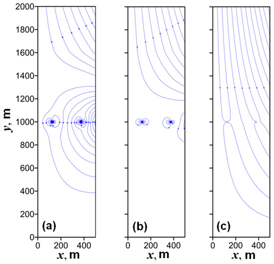
Figure 3.
Groundwater flow lines 1 year (a), 10 years (b) and 100 years (c) after the placement of the HLW.
The weak descending flow induces formation of general ascending currents. The general ascending flow is formed above the descending flow inducing it. This feature of the water flow will limit the migration of radionuclides from the borehole to the Earth’s surface. Already after 10 years, the general downward flow weakens and shifts to the outermost borehole (Figure 3b). At the final stage of the thermos-convective process (after 100 years), the temperatures in the near field of each borehole decreases due to a decrease in heat generation in HLW, but due to conductive heat transfer, rocks outside the near-field are heated. Therefore, the general flow of water becomes only ascending (Figure 3c); however, the velocities of this flow will be lower by orders of magnitude than the velocities in local cells of thermal convection at the beginning of the process.
Thermal convection initiates an ascending flow of groundwater above the heat source; therefore, the domain of polluted groundwater must lengthen out upwards from the HLW packages. Due to the nature of the thermal convection at the beginning of the process, when the flow rates are at their maximum, the effect of ascending thermal convection currents for horizontal boreholes will be less than for vertical boreholes [42]. Hence, the reliability of HLW isolation in a horizontal borehole is higher than in a vertical borehole, in which the upper boundary of the loaded part coincides with the depth of the horizontal borehole. Let us consider as an example a vertical borehole 3 km deep, in the lower part of which waste packages are loaded 2 km long, and a horizontal borehole 2 km long, located at a depth of 1 km. In the vertical borehole, only the upper packages are separated from the biosphere by a rock layer of the same thickness as all packages located in a horizontal borehole. The remaining (lower) packages in a vertical borehole are separated from the Earth’s surface by a thicker layer of rocks and, at the first glance, should be better isolated from the biosphere than in a horizontal borehole. However, the greater extent of the heat source in the case of a vertical borehole causes greater driving forces of thermal convection, dimensions of convective cells and velocities of thermo-convective currents. In the case of horizontal boreholes, the convective cells are not only much smaller, but they also initiate a general downward flow in the overlying at the beginning of the process (Figure 3a). The temperature in the boreholes first increases under the influence of heat generation in the HLW, then decreases due to a decrease in the content of relatively short-lived radionuclides (90Sr, 137Cs, 244Cm). For the basic variant of GDF, this dependence is shown in Figure 4.
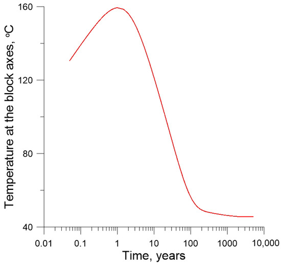
Figure 4.
Time dependence of centerline temperature of the HLW container after its placement in the GDF.
The GDF safety is characterized by the concentration of radionuclides in groundwater at the Earth surface, i.e., . It varies from point to point along the Earth’s surface and is more above the borehole than at a distance from it, so a more informative safety characteristic at a time t is the maximum value C in the water near the Earth’s surface for a given t:
is the mass concentration of a radionuclide (in the both dissolved and colloidal forms). Since C is dimensionless, then is also a dimensionless quantity. The time dependence of is shown in Figure 5 for the basic set of GDF parameters which corresponds to the variant No. 1 in Table 1.
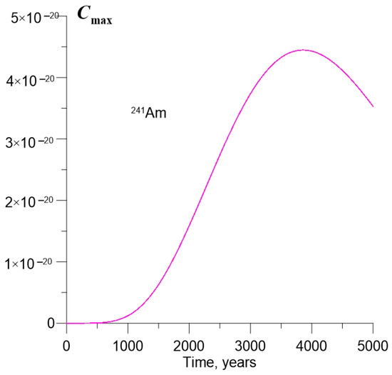
Figure 5.
Change in the maximum concentration of 241Am in near-surface water over time.

Table 1.
Maximum concentration of 241Am (Csup) in water for different calculation options.
Until the polluted groundwater reaches the surface, = 0. Then, as the pollution extends due to convection and hydrodynamic dispersion, the increases and reaches its maximum. Then decreases due to radioactive decay and convection attenuation due to a decrease in heat generation in the HLW. The highest characterizing the maximum level of water pollution at the surface during the lifetime of the GDF is denoted as , and is the time at which Cmax(t) is at its maximum. In order to assess the influence of GDF parameters on , calculations were carried out at their different values as shown in Table 1.
Since the specific activity of 241Am is equal to 129 × 1012 Bq/kg, the groundwater activity of 1 Bq/L corresponds to the value C = 7.75 × 10⁻¹⁵. We obtained C = 4.45 × 10⁻²⁰ for the variant No 1 from Table 1. This guarantees the isolation of 241Am from the biosphere even without delay by rocks due to sorption (i.e., if the radionuclide is transported by the groundwater as a neutral tracer). The half-lives of 90Sr, 137Cs and 244Cm are 15–25 times shorter than those of 241Am; therefore, this variant of the GDF should also ensure isolation of these radionuclides. Sorption of radionuclides and mechanical retention of colloids during the movement of the groundwater through rocks will serve as additional safety factors. An increase in the permeability of the GDF rocks by an order of magnitude (Variant No. 2 of Table 1) will cause an increase in Csup by six orders of magnitude. Hence, Csup will exceed the permissible level for drinking water (1 Bq/L) by 23 times. This indicates the need to select a site for the GDF with minimal fracturing of the rocks, since the permeability depends significantly on fracturing. A decrease in the number of boreholes leads to a significant decrease in ; a decrease in the distance between boreholes from 250 to 100 m (and between the outer boreholes from 1250 to 500 m) reduces slightly (by 17%) due to a decrease in the volume of the hot rock. As a result, the general ascending currents of thermal convection from all boreholes of the GDF are weakened. This explanation is also supported by the decrease in with a decrease in the number of horizontal boreholes from six to four. When the depth of the borehole location decreases from 1000 m to 500 m, the level of 241Am concentration in the groundwater becomes unacceptably high. This is caused by the nature of the groundwater flow. Convection cells, which are formed near individual boreholes, adjoin the area of the ascending flow carrying radionuclides to the Earth’s surface (Figure 6).
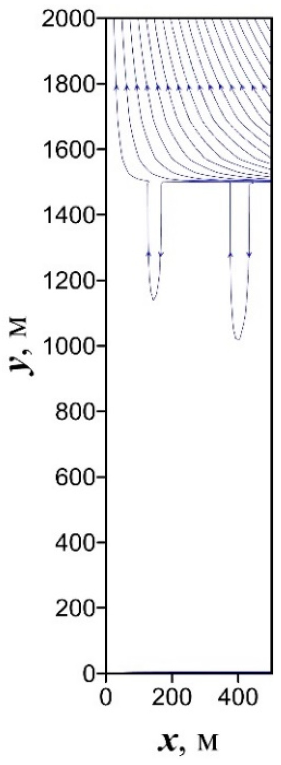
Figure 6.
Groundwater flow streamlines 10 years after HLW loading with boreholes located at a depth of 500 m (calculation for the parameters of Variant No. 5 of Table 1).
The strong dependence of on the depth of the boreholes’ location indicates the possibility of creating a GDF even in fractured rocks by increasing the depth of disposal. With a decrease in the permeability of rocks by an order of magnitude, drops by six orders of magnitude, and an increase in the depth of boreholes with HLW by only a factor of two causes a decrease in by almost ten orders of magnitude. Therefore, doubling the depth of borehole location can compensate for the negative impact of higher rock permeability.
It is worthwhile to assess to what extent the process of radionuclide migration is sensitive to differences in the radionuclide composition of the waste. We assumed that radionuclides are contained in groundwater in a highly mobile colloidal form and can be considered as a neutral tracer. Thus, the geochemical features of individual radionuclides will not affect the simulation results in any way. Obviously, higher concentrations of any radionuclide in the HLW matrix will also lead to higher concentrations of this radionuclide in groundwater that comes to the surface. However, it should be borne in mind that the boundary problem (6)–(9), which models the transfer of radionuclides, is linear with respect to the concentration . Let us denote the actual content of the radionuclide in the matrix as and its maximum mass concentration in the groundwater at the Earth’s surface as . Owing to linearity, , where is the value calculated for radionuclide content in HLW, which was used in our simulation.
An important characteristic of HLW, which depends on the radionuclide composition, is the heat generation rate. Variations of this characteristic cannot be arbitrary. This is due to the fact that the heat generation rate determines the temperature regime of HLW in the GDF. Since the rate of leaching of vitrified HLW by water increases significantly with increasing temperature, the maximum HLW temperature in the GDF is usually limited This imposes implicitly restrictions on the heat generation rate in HLW. Thus, with all the possible diversity of the radionuclide composition of HLW, the level of heat generation in them must comply with these restrictions. The composition used in the calculations satisfies this requirement and, therefore, is consistent from this point of view with another possible real HLW composition.
Thus, the basic version of the GDF will provide safe conditions for the placement of HLW. Calculations show to what extent this result depends on the variation of the governing parameters of the GDF. It should be noted that the assumptions underlying the model underestimate the insulating properties of the GDF’s protective barriers. It was assumed that the permeability of the rocks of the massif is uniform, but it is advisable to choose the site for the creation of the GDF so that the layer of rocks enclosing horizontal boreholes is overlapped by a water-resistant layer of rocks with low permeability [28,33]. It was assumed in the calculations that minor actinides enter the groundwater during the leaching of HLW matrices in colloidal form, and they can be considered as a neutral tracer. The assumption is based on the results of experiments on the leaching of borosilicate glasses with radionuclide simulators. The leaching solution contains at least half of the minor actinide simulators in particles with sizes from 25 nm to 450 nm. However, it must be borne in mind that the transverse dimensions of the pore-fracture channels through which groundwater moves in rocks can be smaller than these particles. This will lead to mechanical retention of colloidal particles carrying radionuclides [58] and increase the protective properties of rocks. Migration of radionuclides from the repository will be prevented by a corrosion-resistant container with a service life of 1000 years [59,60]. Replacing the glass matrix with more stable materials [6,16,47,61] will increase the safety of the GDF. In the above example, the capacity of a GDF with six horizontal boreholes can be estimated as 1–2 thousand tons of HLW, or approximately 10–20% of the potential capacity of a typical shaft-type GDF. A more rational use of borehole GDF is to immobilize the HLW in a compact matrix with the highest possible content of radionuclides, but taking into account the limitations on heat generation as well as on detrimental radiation-induced effects [62,63].
4. Conclusions
The growing demand of the global economy for energy requires a sustainable development of nuclear power engineering (NPE), at least for the next several decades. In the open nuclear fuel cycle of NPE, spent nuclear fuel (SNF) is unloaded from reactors and considered as a waste, whereas in a closed cycle, the SNF is reprocessed to extract actinides and make new fuel. The sustainable development of nuclear power engineering requires safe management of HLW from the closed cycle. According to international consensus, the most effective strategy by now is disposal of solidified HLW in underground repositories of shaft or borehole type in deep geological formations. The advantages of borehole-type GDFs result from smaller volumes of mining operations, a simpler construction technology, shorter construction time and cost. This allows us to consider them as an alternative to shaft-type GDFs. The parts of the boreholes in which waste containers should be placed can be both vertical and horizontal. Mathematical modelling of the migration of radionuclides from a group of parallel horizontal boreholes into the biosphere made it possible to conclude that horizontal GDF boreholes have significant advantages over vertical ones. This is due to the low velocities of regional groundwater flow at depths of the order of a kilometer. That is why the release of radionuclides from the GDF can be caused mainly by thermoconvective flow. The intensity of thermal convection and the scale of the convection cells depend on the vertical size of the heat source. In the case of a horizontal borehole, it is equal to the diameter of the borehole, which is four orders of magnitude less than the length of the vertical borehole loaded with HLW packages. Therefore, the thermo-convective removal of radionuclides from horizontal boreholes is also less. The second advantage of horizontal boreholes is that the temperature of the rocks increases with depth due to the geothermal gradient. In the case of vertical boreholes with a depth of 3–5 kilometers, such an increase in rock temperature will limit the allowable level of waste heat generation rate due to the requirements for the stability of the container and waste forms when accounting for interaction with groundwater, the rate of which increases significantly with increasing temperature. Hence, again, the big advantage of horizontal boreholes is their smaller vertical size.
The objective of future studies is an analysis of radionuclides migration in layered rocks, in particular in the presence of a screen of low-permeable rocks which overlap the GDF boreholes with disposed HLW, as well as an analysis of radionuclides migration from vertically stacked groups of horizontal boreholes.
Author Contributions
Conceptualization, V.M.; resources, S.Y; writing—V.M., S.Y. and M.O., draft preparation—V.M., S.Y. and M.O.; review and editing—V.M., S.Y. and M.O. All authors have read and agreed to the published version of the manuscript.
Funding
The work was carried out at the expense of the Ministry of Science and Higher Education of the Russian Federation, grant No. 13.1902.21.0018 (agreement 075-15-2020-802).
Institutional Review Board Statement
Not applicable.
Informed Consent Statement
Not applicable.
Data Availability Statement
Not applicable.
Acknowledgments
The authors acknowledge the critical comments by anonymous reviewers, which helped to improve the review.
Conflicts of Interest
The authors declare no conflict of interest.
References
- Kopyrin, A.A.; Karelin, A.I.; Karelin, V.A. Technology of Production and Radiochemical Processing of Nuclear Fuel; Atomenergoizdat: Moscow, Russia, 2006. (In Russian) [Google Scholar]
- IAEA. Policies and Strategies for Radioactive Waste Management; Nuclear Energy Series No. NW-G-1.1; IAEA: Vienna, Austria, 2009. [Google Scholar]
- NEA. The Economics of the Back End of the Nuclear Fuel Cycle; NEA OECD: Paris, France, 2013.
- Ewing, R.C.; Whittleston, R.A.; Yardley, B.W.D. Geological Disposal of Nuclear Waste: A Primer. Elements 2016, 12, 233–237. [Google Scholar] [CrossRef]
- NEA. Management and Disposal of High-Level Radioactive Waste: Global Progress and Solutions; NEA OECD: Paris, France, 2020.
- Hench, L.L.; Clark, D.E.; Campbell, J. High Level Waste Immobilization Forms. Nucl. Chem. Waste Manag. 1984, 5, 149–173. [Google Scholar] [CrossRef]
- National Academy of Sciences. End Points for Spent Nuclear Fuel and High-Level Radioactive Waste in Russia and the United States/Committee on End Points for Spent Nuclear Fuel and High-Level Radioactive Waste in Russia and the United States; National Academies Press: Washington, DC, USA, 2003. [Google Scholar]
- Gin, S.; Ribet, I.; Peuget, S.; Delaye, J.-M. Long-term Behavior of Glasses. In Nuclear Waste Conditioning; Pansot, J.-F., Ed.; CEA: Paris, France, 2009; pp. 51–64. [Google Scholar]
- Ojovan, M.; Lee, W.E. Glassy Waste Forms for Nuclear Waste Immobilization. Metall. Mater. Trans. A 2011, 42, 837–851. [Google Scholar] [CrossRef]
- Laverov, N.P.; Yudintsev, S.V.; Kochkin, B.T.; Malkovsky, V.I. The Russian strategy of using crystalline rock as a repository for nuclear waste. Elements 2016, 12, 253–256. [Google Scholar] [CrossRef]
- Ojovan, M.I.; Yudintsev, S.V. Glass, ceramic, and glass-crystalline matrices for HLW immobilisation. Open Ceram. 2023, 14, 100355. [Google Scholar] [CrossRef]
- IAEA. Safety Consideration in the Disposal of Disused Sealed Radioactive Sources in Borehole Facilities; IAEA: Vienna, Austria, 2003. [Google Scholar]
- IAEA. Management of Disused Sealed Radioactive Sources; IAEA: Vienna, Austria, 2014. [Google Scholar]
- Hess, H.H.; Adkins, J.N.; Benson, W.E.; Frye, J.C.; Heroy, W.B.; Hubbert, M.K.; Russel, R.J.; Theis, C.W. The Disposal of Radioactive Waste on Land; Report of the Committee on Waste Disposal of the Division of Earth Sciences; National Academy of Sciences: Washington, DC, USA, 1957; 147p. [Google Scholar] [CrossRef]
- O’Brien, M.T.; Cohen, L.H.; Narasimhan, T.N.; Simkin, T.L.; Wollenberg, H.A.; Brace, W.F.; Green, S.; Platt, H.P. The Very Deep Hole Concept: Evaluation of an Alternative for Nuclear Waste Disposal; Lawrence Berkeley Laboratory: Berkeley, CA, USA, 1979. [Google Scholar] [CrossRef]
- Ringwood, A.E. Disposal of High-Level Nuclear Wastes: A Geological Perspective. Mineral. Mag. 1985, 49, 159–176. [Google Scholar] [CrossRef]
- Crichlow, H.B. Method of Disposing of Nuclear Waste in Underground Rock Formations. U.S. Patent 5,850,614, 15 December 1998. [Google Scholar]
- von Hippel, D.; Hayes, P. Deep Borehole Disposal of Nuclear Spent Fuel and High-Level Waste as a Focus of Regional East Asia Nuclear Fuel Cycle Cooperation; Nautilus Institute: Berkeley, CA, USA, 2010. [Google Scholar]
- Arnold, B.W.; Bauer, S.; Herrick, C.; Pye, S.; Finger, J.; Brady, P.V. Reference Design and Operations for Deep Borehole Disposal of High-Level Radioactive Waste; Sandia National Laboratories: Albuquerque, NM, USA, 2011; 66p. [CrossRef]
- Driscoll, M.J.; Lester, R.K.; Jensen, K.G.; Arnold, B.W.; Swift, P.N.; Brady, P.V. Technology and Policy Aspects of Deep Borehole Nuclear Waste Disposal. Nucl. Technol. 2011, 180, 111–121. [Google Scholar] [CrossRef]
- Swift, P.N.; Arnold, B.W.; Brady, P.V.; Freeze, G.; Hadgu, T.; Lee, J.H. Preliminary Performance Assessment for Deep Borehole Disposal of High-Level Radioactive Waste. Mater. Res. Soc. Symp. Proc. 2012, 1475, 375–384. [Google Scholar] [CrossRef]
- Bates, E.A.; Driscoll, M.J.; Lester, R.K.; Arnold, B.W. Can Deep Boreholes Solve America’s Nuclear Waste Problem? Energy Policy 2014, 72, 186–189. [Google Scholar] [CrossRef]
- Beswick, A.J.; Gibb, F.G.F.; Travis, K.P. Deep Borehole Disposal of Nuclear Waste: Engineering Challenges. Proc. Inst. Civ. Eng. Energy 2014, 167, 47–66. [Google Scholar] [CrossRef]
- Bracke, G.; Charlier, F.; Liebscher, A.; Schilling, F.R.; Röckel, T. About the Possibility of Disposal of HLRW in Deep Boreholes in Germany. Geosciences 2017, 7, 58. [Google Scholar] [CrossRef]
- Bracke, G.; Kudla, W.; Rosenzweig, T. Status of Deep Borehole Disposal of High-Level Radioactive Waste in Germany. Energies 2019, 12, 2580. [Google Scholar] [CrossRef]
- Chapman, N.A. Who Might be Interested in a Deep Borehole Disposal Facility for their Radioactive Waste? Energies 2019, 12, 1542. [Google Scholar] [CrossRef]
- Finsterle, S.; Muller, R.A.; Grimsich, J.; Bates, E.A.; Midgley, J. Post-Closure Safety Analysis of Nuclear Waste Disposal in Deep Vertical Boreholes. Energies 2021, 14, 6356. [Google Scholar] [CrossRef]
- Crichlow, H. Improved Disposal of Intact Spent Nuclear Fuel Assemblies in Ultra Deep Geological Formations in Lateral Boreholes. 2018. Available online: https://www.researchgate.net/publication/330370012 (accessed on 20 July 2023).
- Finsterle, S.; Muller, R.A.; Baltzer, R.; Payer, J.; Rector, J.W. Thermal Evolution Near Heat-Generating Nuclear Waste Canisters Disposed in Horizontal Drillholes. Energies 2019, 12, 596. [Google Scholar] [CrossRef]
- Finsterle, S.; Cooper, C.; Muller, R.A.; Grimsich, J.; Apps, J. Sealing of a Deep Horizontal Borehole Repository for Nuclear Waste. Energies 2021, 14, 91. [Google Scholar] [CrossRef]
- Muller, R.A.; Finsterle, S.; Grimsich, J.; Baltzer, R.; Muller, E.A.; Rector, J.W.; Payer, J.; Apps, J. Disposal of High-Level Nuclear Waste in Deep Horizontal Drillholes. Energies 2019, 12, 2052. [Google Scholar] [CrossRef]
- Krall, L.; McCartin, T.; Macfarlane, A. Siting Deep Boreholes for Disposal of Radioactive Waste: Consequences for Tight Coupling Between Natural and Engineered Systems. Environ. Sci. Technol. 2020, 54, 629–646. [Google Scholar] [CrossRef]
- Kochkin, B.; Malkovsky, V.; Yudintsev, S.; Petrov, V.; Ojovan, M. Problems and Perspectives of Borehole Disposal of Radioactive Waste. Prog. Nucl. Energy 2021, 139, 103867. [Google Scholar] [CrossRef]
- Kochkin, B.T.; Bogatov, S.A. Borehole RW Disposal Concept and Prospects of its Implementation in Russia. Radioact. Waste 2022, 2, 85–99. [Google Scholar] [CrossRef]
- Grigoryan, A.M. Removal of Reservoirs by Multilateral and Horizontal Wells; Nedra: Moscow, Russia, 1969. (In Russian) [Google Scholar]
- Kristiansen, H.; Rapić, A.; Thomsen, H.S.; Kegel, L.; Vuorio, M.; Neckel, W. Boreholes as a Permanent Solution for National Inventories of Radioactive Waste; European Repository Development Organisation (ERDO): Gipf-Oberfrick, Switzerland, 2022. [Google Scholar]
- Swift, P.; Newman, A. Deep Borehole Disposal of Radioactive Waste: Next Steps and Applicability to National Programs; Centre on Global Energy Policy, Columbia SIPA, Columbia University’s School of International and Public Affairs: New York, NY, USA, 2022. [Google Scholar]
- Deep Borehole Demo Work to Be Conducted in Norway. WNN, 9 June 2023. Available online: https://world-nuclear-news.org/Articles/Deep-borehole-demo-work-to-be-conducted-in-Norway (accessed on 18 July 2023).
- Study into Deep Borehole Disposal Costs at Krško. WNN, 10 July 2023. Available online: https://www.world-nuclear-news.org/Articles/Study-into-deep-borehole-disposal-costs-at-Krsko (accessed on 18 July 2023).
- IAEA. Retrievability of High-Level Waste and Spent Nuclear Fuel; TECDOC-1187; IAEA: Vienna, Austria, 2000. [Google Scholar]
- Lari, K.S.; Mallants, D. Coupled Heat-Mass Transport Modelling of Radionuclide Migration from a Nuclear Waste Disposal Borehole. Geofluids 2022, 2022, 5264257. [Google Scholar] [CrossRef]
- Malkovsky, V.; Yudintsev, S. Numerical Analysis of Safety of a Borehole Repository for Vitrified High-level Nuclear Waste. Prog. Nucl. Energy 2022, 144, 104075. [Google Scholar] [CrossRef]
- Zotov, A.V.; Levin, K.A.; Magazina, L.O.; Mukhamet-Galeev, A.P.; Omel’yanenko, B.I.; Samotoin, N.D.; Shapovalov, Y.B. Interaction of Aluminophosphate Glass with Water at Elevated Temperatures. Geochem. Int. 1996, 34, 805–817. [Google Scholar]
- Martynov, K.V.; Zakharova, E.V. Leaching Factors for a Phosphate Radioactive Waste Form under Deep Disposal Conditions. Radioact. Waste 2023, 2, 63–81. [Google Scholar] [CrossRef]
- Yudintsev, S.V.; Malkovsky, V.I.; Kalenova, M.Y. The Thermal Field around a Borehole Repository of Radioactive Waste. Dokl. Earth Sci. 2021, 498, 525–532. [Google Scholar] [CrossRef]
- de Marsily, G. Quantitative Hydrogeology; Academic Press: Orlando, FL, USA, 1986. [Google Scholar]
- Gebhart, B.; Jaluria, Y.; Mahajan, R.L.; Sammakia, B. Buoyancy-Induced Flows and Transport; Hemisphere Publishing Co.: Washington, DC, USA, 1988. [Google Scholar]
- Roache, P. Computational Fluid Dynamics; Hermosa Publishers: Albuquerque, NM, USA, 1976. [Google Scholar]
- Zienkiewicz, O.C.; Morgan, K. Finite Elements and Approximation; John Wiley and Sons: New York, NY, USA, 1983. [Google Scholar]
- Bredehoeft, J.D.; Norton, D.L. Mass and Energy Transport in a Deforming Earth’s Crust. In The Role of Fluids in Crustal Processes; National Academy Press: Washington, DC, USA, 1990; pp. 27–41. [Google Scholar]
- Fried, J.J. (Ed.) Groundwater Pollution: Theory, Methodology, Modelling, and Practical Rules; Elsevier: Amsterdam, The Netherlands, 1975. [Google Scholar] [CrossRef]
- Penrose, W.R.; Polzer, W.L.; Essington, E.H.; Nelson, D.M.; Orlandini, K.A. Mobility of Plutonium and Americium through a Shallow Aquifer in a Semiarid Region. Environ. Sci. Technol. 1990, 24, 228–234. [Google Scholar] [CrossRef]
- Kersting, A.B.; Efurd, D.W.; Finnegan, D.L.; Rokop, D.J.; Smith, D.K.; Thompson, J.L. Migration of Plutonium in Ground Water at the Nevada Test Site. Nature 1999, 397, 56–59. [Google Scholar] [CrossRef] [PubMed]
- Honeyman, B.D. Colloidal Culprits in Contamination. Nature 1999, 397, 23–24. [Google Scholar] [CrossRef]
- Malkovsky, V. Theoretical Analysis of Colloid-facilitated Transport of Radionuclides by Groundwater. In Actinide Nanoparticle Research; Kalmykov, S.N., Denecke, M.A., Eds.; Springer: Berlin, Germany, 2011; pp. 195–243. [Google Scholar]
- Malkovsky, V.I.; Yudintsev, S.V.; Aleksandrova, E.V. Influence of Na-Al-Fe-P Glass Alteration in Hot Non-saturated Vapor on Leaching of Vitrified Radioactive Wastes in Water. J. Nucl. Mater. 2018, 508, 212–218. [Google Scholar] [CrossRef]
- Bates, J.K.; Seitz, M.G.; Steindler, M.J. The Relevance of Vapor Phase Hydration Aging to Nuclear Waste Isolation. Nucl. Chem. Waste Manag. 1984, 5, 63–73. [Google Scholar] [CrossRef]
- Malkovsky, V.I.; Yudintsev, S.V.; Zharikov, A.V. Radiocolloid Retention in the Nizhnekanskii Rock Massif. Dokl. Earth Sci. 2022, 503, 226–231. [Google Scholar] [CrossRef]
- National Environment Agency (NEA). Engineered Barrier Systems and the Safety of Deep Geological Repositories; NEA OECD: Paris, France, 2003.
- Apted, M.J.; Ahn, J. Repository 101: Multiple-barrier Geological Repository Design and Isolation Strategies for Safe Disposal of Radioactive Materials. In Geological Repository Systems for Safe Disposal of Spent Nuclear Fuels and Radioactive Waste, 2nd ed.; Apted, M.J., Ahn, J., Eds.; Woodhead Publishing Series in Energy; Elsevier Ltd.: Amsterdam, The Netherlands, 2017; pp. 3–26. [Google Scholar] [CrossRef]
- Petrov, V.A.; Yudintsev, S.V. Mineral Resources of the Russian Nuclear Industry and Isolation of Radioactive Waste. Geol. Ore Depos. 2023, 65, 469–480. [Google Scholar] [CrossRef]
- Ojovan, M.I. Challenges in the Long-Term Behaviour of Highly Radioactive Materials. Sustainability 2022, 14, 2445. [Google Scholar] [CrossRef]
- Malkovsky, V.I.; Yudintsev, S.V.; Ojovan, M.I.; Petrov, V.A. The Influence of Radiation on Confinement Properties of Nuclear Waste Glasses. Sci. Technol. Nucl. Install. 2020, 14, 8875723. [Google Scholar] [CrossRef]


Disclaimer/Publisher’s Note: The statements, opinions and data contained in all publications are solely those of the individual author(s) and contributor(s) and not of MDPI and/or the editor(s). MDPI and/or the editor(s) disclaim responsibility for any injury to people or property resulting from any ideas, methods, instructions or products referred to in the content. |
© 2023 by the authors. Licensee MDPI, Basel, Switzerland. This article is an open access article distributed under the terms and conditions of the Creative Commons Attribution (CC BY) license (https://creativecommons.org/licenses/by/4.0/).