Article

Comprehensive Analysis of Kinetic Energy Recovery Systems for Efficient Energy Harnessing from Unnaturally Generated Wind Sources

1
Solar Energy Research Institute, Universiti Kebangsaan Malaysia, Bangi 43600, Selangor, Malaysia
2
Department of Mechanical and Manufacturing Engineering, Faculty of Engineering and Built Environment, Universiti Kebangsaan Malaysia, Bangi 43600, Selangor, Malaysia
3
Centre for Fundamental Research, Xpertopedia Academy, Kuala Lumpur 50450, Malaysia
4
Carbon Neutrality Research Group (CNRG), University of Southampton Malaysia, Iskandar Puteri 79100, Johor, Malaysia
5
Department of Electrical and Electronic Engineering, Green University Bangladesh, Narayanganj 1461, Bangladesh
6
Department of Electrical and Computer Engineering, Florida International University, Miami, FL 33174, USA
7
Department of Electrical Engineering, College of Engineering, Taif University, P.O. Box 11099, Taif 21944, Saudi Arabia
8
Institute of Visual Informatics, Universiti Kebangsaan Malaysia, Bangi 43600, Selangor, Malaysia
9
Industrial Engineering and Automotive, Nebrija University, Campus Princesa, C. de Sta. Cruz de Marcenado, 27, 28015 Madrid, Spain
*
Authors to whom correspondence should be addressed.
Sustainability 2023, 15(21), 15345; https://doi.org/10.3390/su152115345
Submission received: 31 August 2023 / Revised: 16 October 2023 / Accepted: 17 October 2023 / Published: 27 October 2023
(This article belongs to the Special Issue Dynamic Operation and Control of Wind Power Systems)

Abstract

:
Alternative energy is a rapidly expanding research area primarily driven by concerns over pollution caused by inefficient conventional energy sources. However, many developing nations rely heavily on these conventional sources. In response, numerous researchers have focused on developing kinetic energy recovery systems (KERS) to capture and utilize the energy lost due to inefficiency. These KERS can be implemented in various scenarios, such as near railroad tracks, industrial flue stacks, cooling towers, and air conditioning outlets. The primary objective of this paper is to critically and comprehensively evaluate the research conducted on the development of these systems. The review reveals that the wind speed in the studied cases ranged between 15 and 22 m/s, providing a consistent and theoretically maximum potential higher than any location worldwide. Furthermore, the impact of these systems on the Betz limit, as well as their drawbacks and crucial advancements necessary for practical implementation, have been thoroughly assessed. This paper contributes to the existing body of knowledge by presenting a comprehensive analysis of the research conducted on KERS development. It highlights the potential of these systems in harnessing untapped energy sources and identifies key areas that require further attention for successful practical application.

1. Introduction

The economic advancement of a nation is very dependent on energy (electricity) [1,2]. While many nations are steadily moving toward renewable energy sources, coal remains affordable. The World Energy Council has noted that Asia alone accounts for 75% of global coal consumption, and the demand for coal-based power is still increasing in the continent of Asia [3]. However, the efficiency of these technologies ranges from 30% to 65%, resulting in immense energy wastage and air pollution. This resulted in the World Bank denying funding requisitions for similar technologies with low efficiency [4,5,6,7,8].
Given the benefits of coal technologies, countries like China and India have turned the focus toward energy efficiency and decarbonization technologies. These technologies include carbon capture and sequestration, carbon capture and utilization, and hydrogen fuel. China launched a “Blue-Sky Plan” in 2018, which suggests steps to ensure the use of energy-efficient technologies [3,9,10,11,12]. Apart from these nations, many countries have investigated energy recovery technologies like district heating and cooling, which help recover industrial waste heat for the heating and cooling purposes [13,14,15].
In Malaysia, energy generation from non-renewable sources amounts to 95%, putting tremendous pressure on energy resources, finances, and the environment. Almost 53% of the energy generated is through coal which must be imported from various countries [16]. In the Paris Agreement in 2016, the Government of Malaysia committed to reducing emissions equivalent to 13.113 million tons of carbon dioxide (CO2) by 2030 [17,18]. Furthermore, the Government has also committed itself to developing green technology to aid the above-said aims. These actions include establishing a feed-in-tariff mechanism to attract investments in renewable energy, green energy technology, and carbon credit-eligible projects [19,20,21,22,23].
Based on the dependence of developing nations on coal, it is necessary to try to increase the efficiency of these technologies. According to Garofalo et al., approximately 30–60% energy is wasted from industrial processes [24]. Another prediction made by Firth et al. indicates that about 49.3–51.5% of global energy use will end up as waste heat in 2030 [25]. A considerable portion of this waste energy is potentially recoverable waste thermal energy. Hence, there is an urgent and essential need for research focused on harnessing this wasted thermal energy [26,27].
Most industrial processes and power plants release flue gas through chimneys at high temperatures and velocities. From the flue gas, there is a potential to recover the waste heat as well as the kinetic energy. As waste flue gas can be considered an unnatural source of wind and by looking at the above statements, industrial stacks can be considered a rich source. This waste energy can be harnessed using a specifically designed energy recovery system (ERS) [28,29]. The ERS can be made by carefully designing the ducting system to optimize power production.
This paper serves as a pioneering effort directed toward comprehending the evolutionary trajectory of wind energy technology and its transformative journey into the innovative realm of kinetic energy recovery systems (KERS). A fundamental understanding of the development of wind energy technologies is imperative for the successful creation of KERS. This encompasses a comprehensive exploration of advancements in airfoil technology given its substantial influence on the energy generation potential of KERS. Additionally, the paper discusses augmentation strategies, a vital aspect for augmenting exergy and consequently enhancing power output, making it an essential consideration for effective KERS development. Furthermore, the KERS undergo critical and fundamental evaluation, illuminating research gaps that necessitate attention and refinement for optimal functionality. Finally, the paper conducts a comprehensive assessment of the financial and environmental impact of KERS, providing valuable insights into their tangible benefits.

2. Wind Power Technologies

Wind power dates to the 1st century. Certain evidence suggests that the technology developed through the 9th century in Persia and the 12th century in Europe. This made it an essential part of the rural economy until cheap fossil fuels replaced it at the beginning of the industrial revolution. The remnants of the technology were seen only in specific niche markets with low economic values [30,31,32].

2.1. Evolution of Wind Energy Generation and Theories

Based on different classes, a wide range of wind turbines are currently available in the market. They are broadly classified as horizontal axis wind turbine (HAWT) and vertical axis wind turbine (VAWT). These classifications are based on the shaft orientation and the rotation axis. Recently, a considerable amount of research has been conducted to modify these wind turbines to be more responsive to the lowest wind speeds and weather conditions (Table 1).
The method to evaluate the performance of a wind turbine is a theory initially introduced to evaluate propellors. This theory was named the blade element momentum theory. This theory uses the mechanical and geometrical parameters and the flow characteristics upon interaction. Two theories—the blade element theory and the momentum theory—are combined to create this model. The former was developed in 1878 to study the turbines from a local perspective by William Froude [34,35]. The turbine blade is divided into sections in this framework, and each section’s blade elements are roughly represented by a planar model. Using this method, the forces acting on the blade element are expressed as functions of the flow characteristics and blade geometry.
The coefficients of lift (CL) and drag (CD)—which account for the forces in the cross-section as functions of the angle of attack, or the angle between the rotating blade and flow—are the basic elements of this model [36,37,38]. Global values are then obtained by integrating the results along the blade. In contrast to the blade element theory, the momentum theory adopts a macroscopic point of view to model the behavior of a column of fluid passing through a turbine. This is also referred to as the disk actuator theory or the axial momentum theory. William J. M. Rankine first proposed the momentum theory in 1865 [35]. Later, independently, Nikolay Joukowsky, Frederick W. Lanchester, and Albert Betz adopted this strategy to create the Betz–Joukowsky limit, which provides the theoretical maximum efficiency of a thin rotor [39,40]. By combining these two methods, Lock et al. carried out their study in 1925 [41]. Hermann Glauert refined the momentum theory by incorporating the rotation of the fluid caused by its interaction with the turbine and formalized it in its modern form in 1926 [42].
Based on the above theories, Table 2 suggests methods that may support the performance augmentation of a wind turbine. Among the given methodologies in Table 2, airfoil optimization, blade optimization, and flow augmentation will be discussed later in different sections of the paper. This is because many of the researchers are working on the development of KERS that is potent and applicable.

2.2. Recent Developments in Air Foils and Blades

Intending to increase power efficiency and control wake turbulence, scientists and researchers have tested biomimetic models of wind turbine blades. In 2015, a slotted turbine blade which was a biomimetic of a layered bird wing [52] was tested by Alejandro et al. In the same year, Ibrahim et al. tested a tubercle wind turbine blade, a biomimetic of a whale fin [53]. These have been noted to show an increase in power efficiency and suppress drag power reduction. Similarly, smart blades have also been explored as a possibility. In 2015, Ref. Alejandro Franco [52] presented an idea to use deformable structures to amplify the efficiency of the aforementioned smart blades.
The reason why energy can be extracted from a wind turbine is due to the electromagnetic effect. This is due to the conversion of kinetic energy into mechanical torque that further drives a generator to convert the energy into electricity [54]. The energy harvested is directly proportional firstly to the cube of velocity, the density of air moving through, and the swept area of the turbine [55]. Hence, to increase the power output, it is necessary to increase either the size or the velocity, and steps have been seen in the same direction. As a matter of fact, the largest wind turbine ever made was by Vestas, with a sweep area of 43,742 m2 and 15 MW capacity [56]. However, the application of such large turbines is next to impossible in urban areas due to space constraints, and some researchers have taken a step forward in increasing the efficiency using different methods as discussed in this part of the paper.
In 2020, the idea of using a radial wind turbine was explored by Acarer et al. It was suggested that the design could be readily used for residential purposes. The airflow that enters through an external casing interacts with the turbine blade tangentially and exits the casing via a chimney [57]. A design with initial optimization using computational fluid dynamics (CFD) simulation and response surface modeling with applications of machine learning algorithms was suggested in 2018 by Wang et al. [58]. Furthermore, artificial-neural-network-assisted meta-modeling to optimize the shape was proposed by Sarkic-Glumac et al. in 2018. A Cp value of 0.29 at λ = 0.55 in the 3D model suggested a staggering 103% improvement in Cp over the designs that had reported the highest efficiency previously [59].
A combination of turbines used in symbiosis is seen in the research developed by Didane et al. in 2020 is and called the contra-rotating wind turbine. This explores the use of the Savonius rotor in combination with the Darrieus rotor. The developed prototype consisted of a Savonius S-type rotor mounted on the top fixed to a shaft while the Darrieus H-type turbine is fixed to the shell of the generator [60]. In this study, the S-type rotor was designed in such a way that it rotates in a clockwise direction while the H-type rotor rotates in a counter-clockwise orientation. The experimental results suggest a conversion efficiency of 42% for torque and 30% for power when subjected to an upstream velocity range from 2 to 9 m/s [61,62].

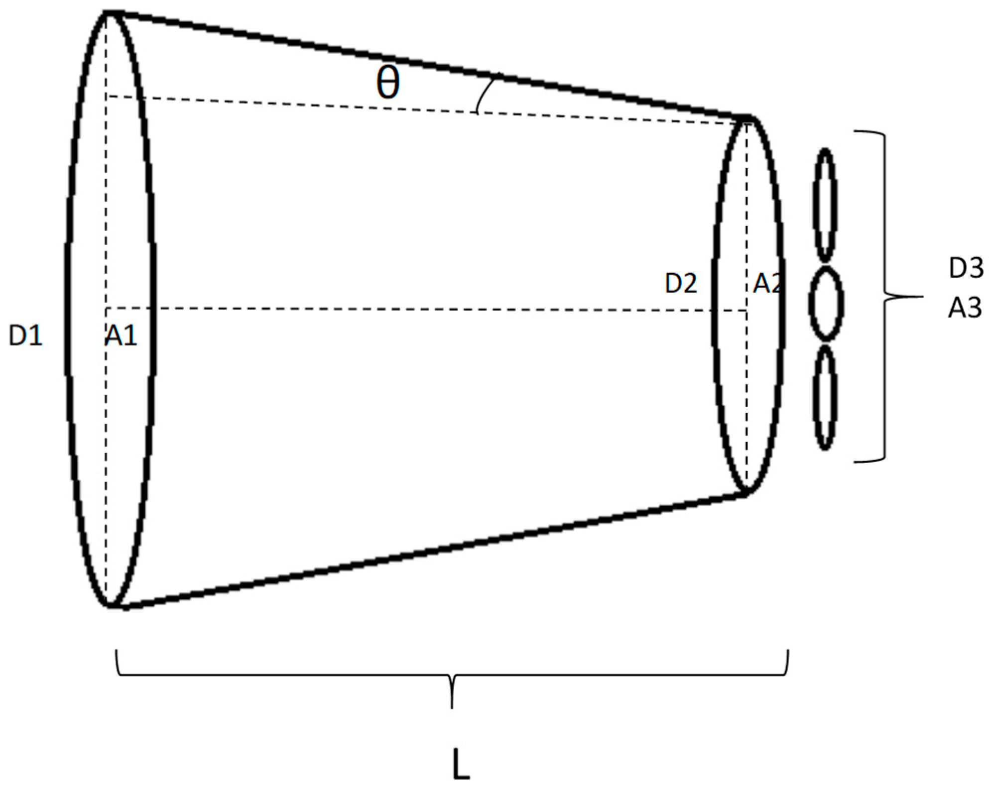
2.3. Theory of Wind Velocity Augmentation

Apart from modifications in turbines and blades to increase the responsiveness to low wind speeds, some researchers are also working on augmenting the speed of the incoming wind. This is important as the power generated by a wind turbine is primarily dependent on the speed of the incoming wind [63]. This can be seen in Equation (1).
Wind   Power   ( P w ) = 1 2 C p A ρ v 3
where:
A : Area of the cross-section of the wind turbine;
ρ : Density of the wind;
v : Wind velocity approaching the turbine;
C p : Power coefficient of the wind turbine.
From Equation (1), the power generated is directly proportional to the cubic power of the velocity. In simple terms, doubling the velocity can increase the power output by a multiple of 8. However, per the Betz limit, the maximum power that can be extracted from a wind source is 59%. This formula assumes the flow to be homogeneous, incompressible, and steady with no losses due to friction. Hence, the maximum extracted power will be considerably less than the Betz limit.
The augmentation of velocity can be achieved using a converging concentrator [63]. Figure 1 shows the placement of the concentrator and the turbine. If an airflow of the velocity V flows into the concentrator from A1, the following observations can be made about the flow:
ο
The velocity increases at the inlet as the area for flow is reduced.
ο
The velocity toward the end increases and reaches the peak at the exit.
This is because the velocity is inversely proportional to the area of the cross-section. Here, we can see Bernoulli’s effect in action as the velocity increases at the expense of pressure energy. Mathematically, this can be given by the continuity equation A 1 V 1 = A 2 V 2 . However, the continuity equation is true only when the flow is incompressible [64]. In a situation where the flow is compressible, a pressure develops at A2, owing to which the density of the fluid changes. Nevertheless, the velocity in wind energy systems is always within the incompressible range, and hence, the continuity equations are applicable.

2.4. Augmentation of Wind Energy Using Ducts and Diffusers

To increase the performance of a wind turbine, an idea to increase the power output by increasing the mass flow rate of wind through the turbine was employed. Some of the pioneering work was done in 1977 by Sabzevari [65], who aimed to increase the operational efficiency of the turbine by simply increasing the tip speed ratio (TSR) and C p using a wind concentrator. The methods used were the introduction of a concentrator before the turbine and a diffuser after it. These could be used only in areas with a constant-directional wind region. Different configurations were used in the process, and the power output was calculated using the measured torque and rotational speeds for the configurations. The results obtained indicated that the concentrators had a positive impact on the rotational speed and in some cases, it was doubled. This marked the beginning of research into the use of concentrators to increase energy output by increasing the mass flow through the turbine.
In 2004, Anzai, Nemoto, and Ushiyama [66] tested different shapes and sizes of cylindrical concentrators. The tested designs were all unidirectional. They concluded that the performance of the turbine was unaffected by the shape of the turbine placed at a reasonably small distance from the outlet of the concentrator. However, when placed inside the concentrator, the performance of the turbine was affected by the shape of the concentrator. The researchers also concluded that the velocity is augmented if: (a) the rotor is positioned behind the outlet of the concentrator, (b) the outlet diameter is smaller than the rotor diameter, and (c) the inlet diameter is much larger than the rotor diameter.
In 2005, Shikha et al. [67] suggested that the length of the concentrator played an important role in the optimum amplification of the wind speed inside the concentrator. Even though the increase in length increased the frictional forces, it rather helped in reducing the angle of incidence and increasing wind velocity parallel to the concentrator wall. Lengths ranging from 25 to 80 cm were tested. The tests revealed 55 cm to be the best concentrator length. The concentrator was a converging type. In 2007, Van Bussel [68] developed a theoretical model based on Betz theory. The analysis was based on the continuity equation and the momentum equation. It was suggested by the researcher that at the downstream of the diffuser, the velocity can be given by the average of the velocities far upstream and far downstream. However, the assumption is seen to be valid only for short diffusers.
In 2013, Chong et al. [69] extended the range of application of concentrators to encompass VAWTs. The researchers developed a novel design known as the omnidirectional guide vane (ODGV). The technology performed well as it concentrated wind from all directions on the VAWT. The researchers compared the performance of a five-bladed H-rotor wind turbine to that equipped with an ODGV. The design was subjected to both physical and CFD tests. The results suggested an increase in the rotational speed of 182% and an increase in the power output by a multiple of 3.48. The system was designed in a way that it could house a rainwater harvesting system and solar panels for hybrid energy. The operation and maintenance costs were compared to that of the power-augmented guide vane, which is a unidirectional concentrator for a similar application. The cost analysis suggested significant savings in the annual operation and maintenance costs. A similar study using a concentrator for a helical Savonius VAWT was conducted by Osman et al. in 2016 [70]. The results suggested better performance of the turbine in terms of angular speed, TSR, and power generated when the concentrator is used.
To gain the benefits of increased mass flow, the INVELOX wind delivery system was subjected to CFD and experimental studies in 2014 by Allaei et al. [71], where the delivery system acts as an area of low pressure, causing the wind to be pulled and further augmented while traveling to a turbine placed at the bottom. The results indicated the system to be insensitive toward wind direction. It also suggested a very low start-up velocity of 1 m/s. Later in 2015, Wanlong Han et al. [72] proposed the use of a low-speed lobed ejector for a one-stage turbine. The proposed design was subjected to simulation by applying the finite volume method using ANSYS CFX software. The results suggested that the turbine could be used for low-speed winds ranging between 2 and 6 m/s, with an energy efficiency of 66–73%. The results also suggested that the pressure at the wind turbine exit decreased. This resulted in an increased mass flow of the wind through the turbine, resulting in a 240% increase in the turbine output. In 2019, E. Koc and T. Yavuz [73] conducted a study to optimize the combination of a concentrator with a flap wind turbine to achieve the best flow velocity through the turbine. The researchers conducted a response surface methodology study (Box–Behnken design). Five parameters were selected for optimization, and each consisted of three values, resulting in 46 combinations. The best-selected combination was subjected to CFD simulations. The researchers considered SG 6043 as the airfoil for the turbine blades, the concentrator, as well as the flaps. The results suggested that the flap-type concentrator effectively increased the flow velocity by a factor of 1.2. They also suggested that a single airfoil-type concentrator increased the velocity by a factor of 1.2.
S. K. Thangavelu et al. [74] designed and simulated the flow of wind through various designs of concentrators. The designs included (a) differentially sized cylindrical-shaped double nozzle concentrators, (b) a streamline-shaped concentrator with a streamline-shaped splitter, (c) differentially sized cone-shaped double nozzle concentrators, and (d) a dual nozzle with a front flange-shaped nozzle and a second nozzle to further augment the velocity. The designs were subjected to rigorous CFD tests. Based on the results, the third design is the best, with an augmentation of 537% of wind velocity.
Rajendra Prasad et al. [75] conducted a study with the core objective of enhancing power extraction from wind by employing a duct augmented wind turbine (DAWT). Specifically, the technical analysis centers on designing and optimizing a duct for a horizontal axis wind turbine. The analysis includes three diffuser ducts: straight wind lens, curved wind lens, and vortex generator (VG) wind lens. The computational analysis also explored the impact of brimmed wind-lens. The results demonstrated notable enhancements in power and mass flow rate, with the curved wind lens and VG-assisted wind lens exhibiting superior performance by generating substantial low-pressure regions through wave formation behind the wind turbine. Computational fluid dynamics analysis further revealed increased power generation, particularly in the case of a curved diffuser wind turbine.
In 2022, Javad Taghinezhad et al. [76] aimed to enhance the power efficiency of ducted wind turbines through the study of aerodynamic modeling and duct optimization. The approach involves designing these turbines based on specific features to determine appropriate wind tunnel dimensions. Previous research utilized analytical and numerical methods to select optimized duct designs. In this study, the impact of critical design parameters like nozzle length, contraction ratio, and outlet diameter on wind turbine performance was thoroughly evaluated. The analytical hierarchy process was applied to identify the best duct design by optimizing multiple criteria responses. A fabricated duct prototype underwent experimental analyses in which the measurement systems estimated pressure distribution and investigated wind speed and flow turbulence. The findings indicated a correlation between the calculated and measured values, demonstrating the effectiveness of the duct design. The study concluded that the optimized duct design positively influenced wind turbine performance, enhancing the overall power efficiency.
In the pursuit of enhancing cross-flow wind turbine efficiency, Mohamed Heragy et al. [77] introduced a wind concentrator using a wind lens concept by attaching two parallel flanged plates to an arc-shaped windshield. Through wind tunnel experiments and CFD simulations, the impact of this wind concentrator on the turbine’s performance was quantified. The experimental results demonstrated a notable 108% increase in the maximum power coefficient, enhancing it from 0.12 to 0.25. Comparatively, the arc-shaped windshield alone improved the coefficient by 48%, elevating it from 0.12 to 0.17. Numerical simulations pinpoint the power enhancement to a downward deflection of the approaching flow due to increased pressure on the upwind side of the upper flange and an overall pressure decrease in the wake of the wind concentrator. This study affirmed that integrating two parallel flanged plates with an arc-shaped windshield significantly enhanced the power performance of a crossflow wind turbine.
The progression of wind energy technology, aimed at augmenting wind turbine performance, has displayed notable advancements. Commencing in 1977, Sabzevari’s [65] seminal work marked the inception of utilizing wind concentrators to enhance turbine efficiency. Subsequent investigations delved into diverse concentrator designs and geometries, illustrating favorable outcomes on rotational speed and power output. Innovations are extended to VAWTs, showcasing substantial improvements in performance metrics. Integration with ducted wind turbines emerged as a promising frontier, as evidenced by recent research achieving a noteworthy increase in the maximum power coefficient. This consistent evolution underscores diligent efforts in refining wind energy technology for a sustainable and efficient energy landscape.

3. The Development of Kinetic Energy Recovery Systems

An ERS is a technique or method by which the input energy to the overall system can be minimized. An example of this would be the application of piezoelectric materials, which help in generating energy from footsteps [78,79]. Sarah Broberg et al. [80] produced a review of such methods that could have the potential of an ERS using excess heat. The technologies suggested were for Gavleborg County in Sweden. The methods included technologies like heat storage using phase change material, heat conversion using the Rankine cycle [81,82,83], thermophotovoltaics [84,85], and the Stirling engine [86,87]. However, the topic of kinetic energy recovery from artificial sources of wind was not covered.

3.1. Latest Trends in the Development of Kinetic Energy Recovery Systems

Few researchers have suggested methods to use wind turbines and concentrators to further augment and harness this untapped source of energy. Chikere et al. [88] stated that many unnatural wind resources are developed globally for power generation. These include solar chimneys, harvesting wind energy from the top of fast-moving trains [89], and ventilated exhaust from the air conditioning system [90]. In 2006, the power extraction from the exhaust gases of automobile engines was studied by Venkatesh. To observe the improvement in the power output, the researcher replaced the radial flow with an axial flow impulse turbine [91].
The work of Chong et al. in 2011, 2013, and 2014 [92,93,94] suggested the use of a VAWT in a crosswind with a five-bladed H-rotor. It was designed to be used over a cooling tower. A small-scale experiment was conducted to test the system. A five-bladed H-rotor with a diameter of 0.3 m was used with an enclosure of 0.4 m. An industrial fan with a 0.4-m diameter was enclosed in a 0.6-m diameter duct. The industrial fan was used to demonstrate a cooling tower. The cooling tower was elevated by 0.1 m from the floor. A wind turbine in the enclosure was placed above the cooling tower (simulated). The results suggest that the system can be applied without any negative effect on the cooling tower; moreover, the enclosure increased energy generation by 30.4%.
Aja Ogboo Chikere et al. [88] suggested the use of industrial flue gas to increase the efficiency of the solar chimney power plant (SCPP). The efficiency of this system has been regarded as low when compared to the investment cost. This system is known as a “hybrid solar-flue gas chimney”. Al-Kayiem et al. [95] suggested certain modifications to the existing design of SCPP. The researchers suggested that by increasing the mass flow rate from 0.18 to 0.24 kg/s, a velocity increase from 4.1 to 4.6 m/s could be observed. A Savonius rotor wind turbine can be used to harness this velocity. Theoretically, the system has certain environmental benefits, which include reduction in thermal pollution.
Nikhita Chilugodu et al. [89] proposed the use of a VAWT in the vicinity of the Singapore MRT system. The findings from the CFD simulations suggested that the kinematic movement of the trains induced enough wind speed for the system to work. The velocity noted was in the range of 6–8 m/s. As it was seen that the velocity increased with the height, the turbine was installed on an integrated hydraulic lift. An increase of 5 m in height would also increase the energy efficiency by 0.2%. As per the simulations, the energy can be harvested using a 2-kW VAWT. The annual energy generation was 600,000 Wh/year.
In 2013, Md. Abir et al. [96] proposed the use of waste exhaust air. Exhaust fans are intended to facilitate the circulation and ventilation of air in industries. The data of the wind speed of the exhaust gas were compared against that of certain on- and offshore wind farms. The selected locations were Germany and Bangladesh. In accordance with the data, the wind speed measured at the exhaust ranged between 14.5 and 16 m/s, whereas the wind speed at different wind farms ranged between 4 and 5 m/s. Hence, in congruence with the data, the calculations estimated the energy output of both ranges of area. The calculations indicated that the maximum energy generation capacity from just one factory site is 1.40 MW.
Mann and Singh [97,98,99] introduced a novel concept in the use of flue gas to generate energy using the concept of DAWT and analyzed it using a six-bladed wind turbine. The system was tested with different diffuser angles of 7°, 11°, and 15° for turbulence and back forces. The results obtained through simulations suggested that energy extraction can be increased by 18.25%.
In 2020, Wachira Puttichaem et al. [100,101] proposed the possibility of a negative impact on the system due to the implementation of traditional wind turbines. The analysis of the actuator disk theory can be used as a support to the researchers’ statement. The researchers proposed the use of a shaftless small-scale horizontal wind turbine (SSHWT). The developed prototype was 50 cm in diameter. It was mounted in front of an industrial exhaust fan 5 cm along the axis. The current consumption of the exhaust fan was measured with and without the prototype. The results indicated no negative impact on the exhaust system. As the system does not contain a shaft, the researchers had to develop a novel generator system. The novel generator system is a new take on the brushless direct current (BDC) generator. The system was tested with the BDC in which the sets of magnets were varied. The best result was seen with eight sets of magnets as adding more sets of magnets would hinder the spin of the blades. The results suggested a maximum efficiency of 51%. In the same year, Zishan et al. [102] produced a mathematical model for an ERS of an industrial stack. The researchers suggested the modification of the stack into a converging-diverging nozzle. This would help in keeping the exit velocity within the advised range, preventing the exhaust pollutants from dispersing at a lower altitude.
A study done by Douglas Yeboah et al. [103] focused on exploring the recovery of wind energy from the exhaust of an underground mine using experimental analysis. The research revealed a reduction in wind velocity at a frequency of −2.5162 Hz as distance increased. This frequency predicted a wind speed of 7.67 m/s at 1 m from the exhaust fan within a real mine. Theoretical calculations highlighted a substantial wind energy potential of 1031.31 kWh over a 13 h period, equivalent to 79.3 kW. Realistic estimations indicated that around 55.51 kW of wind power could be recovered, resulting in an estimated 721.63 kWh of energy. When compared to previous mining industry studies, the recovery potential showed variation based on specific site factors. The study demonstrated a theoretically recoverable power percentage of 28%, up to 19.8% in realistic scenarios, underscoring wind energy’s potential in underground mining. Furthermore, wind energy significantly contributes to the lighting system, enhancing overall energy efficiency. Recommendations for optimization include upgrading the ventilator fan system, utilizing multiple fans, and optimizing the system’s design. The study emphasizes the importance of continuous research and real-world implementations to achieve energy savings.
From Table 3, it can be seen that the strides in the direction toward developing a novel ERS using waste artificial sources of wind are ample. However, there remains considerable area for future research.
Md. Abir et al. [96] highlighted the importance of the ducting and diffuser system in the application of energy recovery. Many of these technologies can benefit from novel concentrator and diffuser designs.
An SCPP works due to the phenomenon called convection, in which air that is heated by solar collectors rises through the chimney and allows a turbine to convert kinetic energy into electrical energy [104]. The heat transfer rate is given by the equation Q = h A T , where h is the convection heat transfer coefficient, A is the exposed surface area, and T is the temperature difference. From the equation, the factors determining the efficiency of this system include the quality of thermal energy as well as the area and height of the chimney [104,105]. Nonetheless, a traditional SCPP that depends solely on solar energy has a low conversion efficiency, and to make the conversion efficiency viable, the amount of investment required is enormous, making it difficult to self-sustain. An alternate method to increase the efficiency as suggested by Al-Kayiem [88] is to use industrial flue gas. Practically, the results were far better than the normal SCPP but problematic as the space required in the industrial zone would be enormous for such a set-up.
Researchers have analyzed the applicability of ERS and the scope for new research in the field. Nikhita Chilugodu et al. [89] used wind-generated power due to the suction created by the movement of the trains, where the strategic placement of INVELOX could help augment and improve the performance of both ideas. Hence, a CFD study integrating the two ideas could help in introducing the concept.
Mann and Singh [97,98,99] suggested the use of two bent ducts attached to horizontal convergent-divergent nozzles. Even though the ducts would help in maintaining the velocity as suggested by Md. Abir et al. [96], the major issue would be the back force of the turbine on the system. This may be supported by the actuator disk theory, which suggests that the velocity of the stream decreases by roughly 66% after the turbine, which—when combined with the force of the wind coming from the opposite direction—may cause certain issues in the system. A detailed Gaussian plume model study would be necessary for this purpose. The second issue would be the distribution of the pollutants at a low altitude. This may result in serious environmental issues. Hence, using the design would be practically impossible as the damage would outweigh the gains from energy recovery.
Figure 2d shows the suggested designs by Chong et al. in 2012 and 2013 [93,106], respectively. The design suggested in 2013 shows a single VAWT for the system, in which only a small portion of the exhaust was covered, leaving a large portion untapped. The position was decided by considering the regions with the highest wind speeds. However, the researchers failed to consider the impact of free-stream wind, which may cause a shift in the air coming from the exhaust. Even though this was taken care of by employing the second VAWT, the wastage of exhaust wind is still not addressed. Similarly, the design suggested by Wachira Puttichaem et al. [100] has the same issue of wind wastage through the centermost region. Although researchers may argue the benefits of the SSWT in terms of reducing the negative impact on the base system, a careful study would show that the efficiency is barely at 51%. Furthermore, the generator configuration may open a whole new area for research in the improvement of the ERS. Similarly, Douglas Yeboah et al. [103] highlighted the impact of deploying the wind turbine on the exhaust system as this may have an adverse impact on the circulation of wind inside the underground mines. Currently, many researchers have turned their focus toward the development of piezoelectric cantilevers and microcantilevers for wind energy harvesting. Some researchers have also started looking into it as a micro-charger for supercapacitors, which can be employed for use on-site. Likewise, if a system is designed to store energy on-site like the system designed by Chong et al. [106], it would significantly reduce the cost of operation of the system.

3.2. Future Avenues of Development

In order for a field of research to reach its maturity, an understanding of untouched avenues is necessary. Based on the preceding section, it can be deduced that the ongoing research pertaining to the evolutionary development of KERS from wind turbines is in its nascent stages. Following are the gaps and points of improvement in the field:
  • Most of the research in the field of energy recovery is based on heat recovery and only a handful amount of literature is available on KERS.
  • Most of the studies done have visible issues in their applicability.
  • The scarce understanding of the impact of actuator disk theory—in particular the negative impact of the back force generated due to the shear nature of the turbine—is a major drawback.
To propel the research toward maturity, the avenues above must be addressed. To do so, the following steps can be taken into consideration:
  • Encourage further research, capacity building, and industry collaboration to understand the status quo better.
  • LES-based simulative studies should be conducted to obtain a detailed analysis of the overall impact on the system.
  • Development of novel mathematical models that can better explain the forces in play around the turbine and within the system.
  • Development and evaluation of prototypes.
  • Particle-image-velocimetry-based studies describe the fluid flow better and in real-time as compared to simulations.

3.3. Wind Turbine Efficiency against the Betz Limit

A wind turbine cannot convert more than 16/27 (59.3%) of the kinetic energy of wind into mechanical energy turning a rotor, according to a German physicist Albert Betz, who came to this conclusion in 1919. This is still referred to as the Betz limit or the Betz law. This limit stems from the inherent limitations of wind turbines rather than inefficiencies in the generator. In 1999, Hansen et al. [107] showed by means of CFD computations “…that the Betz limit can be exceeded with the ratio corresponding to the relative increase in mass flow through the rotor”. A simple momentum theory for DAWTs was also derived at that time by the author using several assumptions. It is assumed that there is no viscous wake mixing process behind the diffuser, but the effect of negative backpressures is taken into account in the performance prediction. From this DAWT momentum theory, it can be seen that the achievable power is comparable to the power of a normal HAWT with a diameter equal to the exit diameter of the diffuser. However, from this momentum model, it can also be seen that better performances are possible when a substantial low “back-pressure level” can be achieved at the diffuser exit.
As seen in the research done by Mann and Singh [97,98,99] and Al-Kayiem [95], the turbines are housed in a duct, which is an augmentation method. The mass flow through the turbine increases to a great extent. Due to this, these systems can exceed the Betz limit. However, in the case of Al-Kayiem [95], the position of the turbine in the SCPP would impact its ability to exceed the Betz limit. Locating the turbine at a high point in the duct can cause the back force to reduce significantly. In the research by Wachira Puttichaem et al. [100,101], the researchers suggested an efficiency of 51%, which is close to the Betz limit. From this, it is clear that housing such SSHWT within an augmentation device would increase its efficiency exponentially. Nevertheless, the open section in the middle would waste a lot of airflow, and a sufficiently big section may end up decreasing efficiency below the Betz limit.
In the case of Chong et al. [94], the guided vanes might not be as useful as the flow would continue to form a stream tube, hence wasting a considerable amount of flow. The use of ODGV on the top of cooling towers might be of help as it may increase the mass flow of the wind. Even though the research done by Nikhita Chilugodu et al. [89] used wind created by suction rather than regular flow, it still created a stream tube around the turbine, reducing the efficiency below the Betz limit. However, if the system is augmented with INVELOX as suggested above, it will augment the velocity of the flow and also increase the flow through the turbine, violating the Betz limit and making the system highly efficient.

3.4. Financial Benefits

Considering a counterflow cooling tower with a blower fan for residential areas, the power consumption of the same is in the range of 20–40 kW. As per the study by Chong et al. [69,106], 13% of the power required by the cooling tower can be recovered. Likewise, for the study by Wachira Puttichaem et al. [101], an energy recovery of 51% was obtained from the stream. In monetary terms, the savings are enormous.
For the study of Zishan et al. [102], design B can extract 40.103 kW. The study was conducted for a 600 MW coal-powered power plant. Running the power plant for 8 h in the peak period would result in a quarterly saving of INR 275,266.99 or equivalent to RM 13,667.10. Similarly, Mann, and Singh [97] suggested that they could recover 34.92 kW for NACA 4412 with a diffuser angle of 7°. With similar time considerations, significant financial savings of INR 239,690.88 or equivalent to RM 11,900.736 can be made.

3.5. Environmental Benefits

Considering an assumed efficiency of approximately 33% for a 600 MW coal-fired power plant using sub-bituminous coal, the intricacies of energy production are examined. Sub-bituminous coal, a widely utilized energy source, exhibits an energy content that can fluctuate but generally hovers around an average of 21 million MMBtu/ton.
In this context, for the power plant to run optimally over an 8 h daily operational period, an estimated quantity of 693.02 tons of sub-bituminous coal is required. This amount of coal serves as the fuel necessary to sustain the plant’s energy generation at the specified power output and time frame.
However, the combustion of this coal is not without its ecological implications. When 693.02 tons of sub-bituminous coal is burned, the resulting combustion gases include CO2 among other by-products. Specifically, this amount of coal combustion yields approximately 1652.52 tons of CO2 emissions daily.
To appreciate the broader environmental impact, we extend our analysis to a yearly scale. Over the course of a year, this power plant’s operations would translate to a substantial reduction of approximately 603,169.8 tons of CO2 emissions. This noteworthy reduction is a testament to the positive contribution of utilizing sub-bituminous coal, portraying its potential in mitigating greenhouse gas emissions and consequently benefitting the environment on a significant scale.

4. Conclusions

In conclusion, to attain maturity in the field of research related to kinetic energy recovery systems (KERS) derived from wind turbines, it is imperative to recognize the unexplored domains and address prevalent gaps. Presently, research in this area is in its infancy, requiring thorough exploration and refinement. The identified gaps include a lack of comprehensive literature focusing on KERS, noticeable applicability issues in existing studies, and a deficient understanding of the actuator disk theory, particularly concerning the adverse effects of back force generated by the turbine’s shear nature.
To advance this field towards maturity, several critical steps must be taken. Firstly, promoting further research, encouraging capacity building, and fostering collaboration between academia and industry will deepen comprehension of the present state of the field. Secondly, conducting studies based on large eddy simulation (LES) will offer a detailed analysis of the system’s impact, providing a more comprehensive understanding of the involved phenomena. Thirdly, developing advanced mathematical models to elucidate intricate forces at play within the system will enhance predictive accuracy and comprehension. Additionally, rigorous prototyping and evaluation, bridging the gap between theoretical simulations and practical applications, are essential. Lastly, implementing particle-image-velocimetry-based studies, which offer real-time depiction of fluid flow, will provide invaluable insights beyond simulations.
By systematically addressing these gaps and implementing the suggested steps, the field of research concerning the evolutionary development of KERS from wind turbines can progress towards maturity, fostering more effective and sustainable energy recovery systems.

Author Contributions

Conceptualization, S.Z.; formal analysis, S.Z. and A.F.; funding acquisition, O.M.A.; project administration, S.Z., K.H.W., A.F. and O.M.A.; resources, K.H.W. and A.F.; software, K.H.W.; supervision, M.S.H.L.; visualization, M.T. and O.M.A.; writing—original draft, S.Z.; writing—review and editing, A.H.M., H.R., M.S.H.L., M.T., O.M.A. and M.R.S. All authors have read and agreed to the published version of the manuscript.

Funding

This research was funded by Deanship of Scientific Research, Taif University.

Institutional Review Board Statement

Not applicable.

Informed Consent Statement

Not applicable.

Data Availability Statement

The data are available upon reasonable request.

Acknowledgments

The researchers would like to acknowledge Deanship of Scientific Research, Taif University for funding this work.

Conflicts of Interest

The authors declare no conflict of interest.

References

  1. Uzar, U. Political Economy of Renewable Energy: Does Institutional Quality Make a Difference in Renewable Energy Consumption? Renew. Energy 2020, 155, 591–603. [Google Scholar] [CrossRef]
  2. Burke, M.J.; Stephens, J.C. Political Power and Renewable Energy Futures: A Critical Review. Energy Res. Soc. Sci. 2018, 35, 78–93. [Google Scholar] [CrossRef]
  3. Gadonneix, P.; Sambo, A.; Guobao, Z.; Kim, Y.D.; Teyssen, J.; Lleras, J.A.V.; Naqi, A.A.; Meyers, K.; Shin, H.C.; Nadeau, M.-J.; et al. World Energy Issues Monitor 2020. World Energy Council 2020. Available online: https://www.worldenergy.org/ (accessed on 2 September 2023).
  4. He, H.; Fu, Y.; Zhao, T.; Gao, X.; Xing, L.; Zhang, Y.; Xue, X. All-Solid-State Flexible Self-Charging Power Cell Basing on Piezo-Electrolyte for Harvesting/Storing Body-Motion Energy and Powering Wearable Electronics. Nano Energy 2017, 39, 590–600. [Google Scholar] [CrossRef]
  5. Qamruzzaman, M.; Karim, S. Does Public-Private Investment Augment Renewable Energy Consumption in BIMSTEC Nations? Evidence from Symmetric and Asymmetric Assessment. Energy Strateg. Rev. 2023, 49, 101169. [Google Scholar] [CrossRef]
  6. Alola, A.A.; Onifade, S.T.; Magazzino, C.; Obekpa, H.O. The Effects of Gas Flaring as Moderated by Government Quality in Leading Natural Gas Flaring Economies. Sci. Rep. 2023, 13, 14394. [Google Scholar] [CrossRef] [PubMed]
  7. Alam, M.M.; Murad, M.W. The Impacts of Economic Growth, Trade Openness and Technological Progress on Renewable Energy Use in Organization for Economic Co-Operation and Development Countries. Renew. Energy 2020, 145, 382–390. [Google Scholar] [CrossRef]
  8. Kim, J.; Lee, S.; Tahmasebi, A.; Jeon, C.-H.; Yu, J. A Review of the Numerical Modeling of Pulverized Coal Combustion for High-Efficiency, Low-Emissions (HELE) Power Generation. Energy Fuels 2021, 35, 7434–7466. [Google Scholar] [CrossRef]
  9. Zhou, D.; Wang, F.; Zhao, X.; Yang, J.; Lu, H.; Lin, L.Y.; Fan, L.Z. Self-Chargeable Flexible Solid-State Supercapacitors for Wearable Electronics. ACS Appl. Mater. Interfaces 2020, 12, 44883–44891. [Google Scholar] [CrossRef]
  10. Liu, Y.; Yang, S.; Liu, X.; Guo, P.; Zhang, K. Driving Forces of Temporal-Spatial Differences in CO2 Emissions at the City Level for China’s Transport Sector. Environ. Sci. Pollut. Res. 2021, 28, 25993–26006. [Google Scholar] [CrossRef]
  11. Winter, A.K.; Le, H.; Roberts, S. From Black to Blue Skies: Civil Society Perceptions of Air Pollution in Shanghai. China Q. 2021, 248, 1059–1080. [Google Scholar] [CrossRef]
  12. Mo, T. Design of Energy and Powertrain Systems for Electric Buses Based on Driving Cycles and Multiple Criteria. Ph.D. Thesis, Swinburne University of Technology Melbourne, Melbourne, Australia, 2022. [Google Scholar]
  13. Rezaie, B.; Rosen, M.A. District Heating and Cooling: Review of Technology and Potential Enhancements. Appl. Energy 2012, 93, 2–10. [Google Scholar] [CrossRef]
  14. Werner, S. International Review of District Heating and Cooling. Energy 2017, 137, 617–631. [Google Scholar] [CrossRef]
  15. Atienza-Márquez, A.; Bruno, J.C.; Coronas, A. Recovery and Transport of Industrialwaste Heat for Their Use in Urban District Heating and Cooling Networks Using Absorption Systems. Appl. Sci. 2020, 10, 10291. [Google Scholar] [CrossRef]
  16. Oh, T.H.; Hasanuzzaman, M.; Selvaraj, J.; Teo, S.C.; Chua, S.C. Energy Policy and Alternative Energy in Malaysia: Issues and Challenges for Sustainable Growth—An Update. Renew. Sustain. Energy Rev. 2018, 81, 3021–3031. [Google Scholar] [CrossRef]
  17. Cederborg, A.J.; Snöbohm, S. Is there a Relationship between Economic Growth and Carbon Dioxide Emissions? Economic 2016. [Google Scholar] [CrossRef]
  18. Mohd Chachuli, F.S.; Ahmad Ludin, N.; Md Jedi, M.A.; Hamid, N.H. Transition of Renewable Energy Policies in Malaysia: Benchmarking with Data Envelopment Analysis. Renew. Sustain. Energy Rev. 2021, 150, 111456. [Google Scholar] [CrossRef]
  19. Sarkar, M.S.K.; Al-Amin, A.Q.; Filho, W.L. Revisiting the Social Cost of Carbon after INDC Implementation in Malaysia: 2050. Environ. Sci. Pollut. Res. 2019, 26, 6000–6013. [Google Scholar] [CrossRef]
  20. Rahmat, M.A.A.; Abd Hamid, A.S.; Lu, Y.; Ishak, M.A.A.; Suheel, S.Z.; Fazlizan, A.; Ibrahim, A. An Analysis of Renewable Energy Technology Integration Investments in Malaysia Using HOMER Pro. Sustainability 2022, 14, 13684. [Google Scholar] [CrossRef]
  21. Shahida, N.; Suhaime, M.; Suheel, S.Z.; Safwan, A.A. Energy Distribution and Economic Analysis of a Residential House with the Net-Energy Metering Scheme in Malaysia. Int. J. Electr. Comput. Eng. 2022, 12, 2313–2322. [Google Scholar] [CrossRef]
  22. Abdullah, W.M.Z.B.W.; Zainudin, W.N.R.A.B.; Ishak, W.W.B.M.; Sulong, F.B.; Zia Ul Haq, H.M. Public Participation of Renewable Energy (Ppred) Model in Malaysia: An Instrument Development. Int. J. Renew. Energy Dev. 2020, 10, 119–137. [Google Scholar] [CrossRef]
  23. Razali, A.H.; Pauzi Abdullah, M.; Hassan, M.Y.; Said, D.M.; Hussin, F. Net Energy Metering Scheme Based on Time of Use Pricing for Residents in Malaysia. Indones. J. Electr. Eng. Comput. Sci. 2020, 19, 1140–1146. [Google Scholar] [CrossRef]
  24. Garofalo, E.; Bevione, M.; Cecchini, L.; Mattiussi, F.; Chiolerio, A. Waste Heat to Power: Technologies, Current Applications, and Future Potential. Energy Technol. 2020, 8, 2000413. [Google Scholar] [CrossRef]
  25. Firth, A.; Zhang, B.; Yang, A. Quantification of Global Waste Heat and Its Environmental Effects. Appl. Energy 2019, 235, 1314–1334. [Google Scholar] [CrossRef]
  26. Forman, C.; Muritala, I.K.; Pardemann, R.; Meyer, B. Estimating the Global Waste Heat Potential. Renew. Sustain. Energy Rev. 2016, 57, 1568–1579. [Google Scholar] [CrossRef]
  27. Miró, L.; Gasia, J.; Cabeza, L.F. Thermal Energy Storage (TES) for Industrial Waste Heat (IWH) Recovery: A Review. Appl. Energy 2016, 179, 284–301. [Google Scholar] [CrossRef]
  28. Zhang, Q.; Zhao, X.; Lu, H.; Ni, T.; Li, Y. Waste Energy Recovery and Energy Efficiency Improvement in China’s Iron and Steel Industry. Appl. Energy 2017, 191, 502–520. [Google Scholar] [CrossRef]
  29. He, K.; Wang, L.; Li, X. Review of the Energy Consumption and Production Structure of China’s Steel Industry: Current Situation and Future Development. Metals 2020, 10, 302. [Google Scholar] [CrossRef]
  30. Sahin, A.D. Progress and Recent Trends in Wind Energy. Prog. Energy Combust. Sci. 2004, 30, 501–543. [Google Scholar] [CrossRef]
  31. Patel, S.; Parkins, J.R. Assessing Motivations and Barriers to Renewable Energy Development: Insights from a Survey of Municipal Decision-Makers in Alberta, Canada. Energy Rep. 2023, 9, 5788–5798. [Google Scholar] [CrossRef]
  32. Bontempo, R.; Manna, M. Diffuser Augmented Wind Turbines: Review and Assessment of Theoretical Models. Appl. Energy 2020, 280, 115867. [Google Scholar] [CrossRef]
  33. Schubel, P.J.; Crossley, R.J. Wind Turbine Blade Design. Energies 2012, 5, 3425–3449. [Google Scholar] [CrossRef]
  34. Okulov, V.; Kuik, G. The Betz-Joukowski Limit: On the Contribution to Rotor Aerodynamics by the British, German and Russian Scientific Schools. Wind Energy 2012, 15, 335–344. [Google Scholar] [CrossRef]
  35. Kramm, G.; Sellhorst, G.; Ross, H.K.; Cooney, J.; Dlugi, R.; Mölders, N. On the Maximum of Wind Power Efficiency. J. Power Energy Eng. 2016, 4, 1. [Google Scholar] [CrossRef]
  36. Chaviaropoulos, P.K.; Hansen, M.O.L. Investigating Three-Dimensional and Rotational Effects on Wind Turbine Blades by Means of a Quasi-3d Navier-Stokes Solver. J. Fluids Eng. Trans. ASME 2000, 122, 330–336. [Google Scholar] [CrossRef]
  37. Du, Z.; Selig, M. A 3-D Stall-Delay Model for Horizontal Axis Wind Turbine Performance Prediction. In 1998 ASME Wind Energy Symposium; Aerospace Sciences Meetings; American Institute of Aeronautics and Astronautics: Reston, VA, USA, 1998. [Google Scholar]
  38. Elliott, D.L. Status of Wake and Array Loss Research. In Proceedings of the 21 American Wind Energy Association Conference: Windpower ’91, Palm Springs, CA, USA, 24–27 September 1991; pp. 224–227. [Google Scholar]
  39. van Kuik, G.A.M. The Lanchester–Betz–Joukowsky Limit. Wind Energy 2007, 10, 289–291. [Google Scholar] [CrossRef]
  40. Van Kuik, G.A.M.; Sørensen, J.N.; Okulov, V.L. Rotor Theories by Professor Joukowsky: Momentum Theories. Prog. Aerosp. Sci. 2015, 73, 1–18. [Google Scholar] [CrossRef]
  41. Lock, C.N.H.; Bateman, H.; Townend, H.C.H. An Extension of the Vortex Theory of Airscrews with Applications to Airscrews of Small Pitch, Including Experimental Results; HMSO London: London, UK, 1926. [Google Scholar]
  42. Glauert, H. The Elements of Aerofoil and Airscrew Theory; Cambridge Science Classics; Cambridge University Press: Cambridge, UK, 1983; ISBN 9780521274944. [Google Scholar]
  43. Yuan, Z.; Jiang, J.; Zang, J.; Sheng, Q.; Sun, K.; Zhang, X.; Ji, R. A Fast Two-Dimensional Numerical Method for the Wake Simulation of a Vertical Axis Wind Turbine. Energies 2021, 14, 49. [Google Scholar]
  44. Tang, S.; Tian, D.; Huang, M.; Li, B.; Tao, L. Load Control Optimization Method for Offshore Wind Turbine Based on LTR. Energy Rep. 2021, 7, 4288–4297. [Google Scholar] [CrossRef]
  45. Zadorozhna, D.B.; Benavides, O.; Grajeda, J.S.; Ramirez, S.F.; de la Cruz May, L. A Parametric Study of the Effect of Leading Edge Spherical Tubercle Amplitudes on the Aerodynamic Performance of a 2D Wind Turbine Airfoil at Low Reynolds Numbers Using Computational Fluid Dynamics. Energy Rep. 2021, 7, 4184–4196. [Google Scholar] [CrossRef]
  46. Abdelsalam, A.M.; Kotb, M.A.; Yousef, K.; Sakr, I.M. Performance Study on a Modified Hybrid Wind Turbine with Twisted Savonius Blades. Energy Convers. Manag. 2021, 241, 114317. [Google Scholar] [CrossRef]
  47. Zadeh, M.N.; Pourfallah, M.; Sabet, S.S.; Gholinia, M.; Mouloodi, S.; Ahangar, A.T. Performance Assessment and Optimization of a Helical Savonius Wind Turbine by Modifying the Bach’s Section. SN Appl. Sci. 2021, 3, 1–11. [Google Scholar] [CrossRef]
  48. Wang, H.; Jiang, X.; Chao, Y.; Li, Q.; Li, M.; Chen, T.; Ouyang, W. Numerical Optimization of Horizontal-Axis Wind Turbine Blades with Surrogate Model. Proc. Inst. Mech. Eng. Part A J. Power Energy 2020, 235, 1173–1186. [Google Scholar] [CrossRef]
  49. Paranjape, A.D.; Bajaj, A.S.; Palanganda, S.T.; Parikh, R.; Nayak, R.; Radhakrishnan, J. Computational Analysis of High-Lift-Generating Airfoils for Diffuser-Augmented Wind Turbines. Wind Energy Sci. 2021, 6, 149–157. [Google Scholar] [CrossRef]
  50. Mohammadi, M.; Mohammadi, R.; Ramadan, A.; Mohamed, M.H. Numerical Investigation of Performance Refinement of a Drag Wind Rotor Using Flow Augmentation and Momentum Exchange Optimization. Energy 2018, 158, 592–606. [Google Scholar] [CrossRef]
  51. Dighe, V.V.; de Oliveira, G.; Avallone, F.; van Bussel, G.J.W. On the Effects of the Shape of the Duct for Ducted Wind Turbines. Wind Energy Symp. 2018, 2018, 997. [Google Scholar] [CrossRef]
  52. Alejandro Franco, J.; Carlos Jauregui, J.; Toledano-Ayala, M. Optimizing Wind Turbine Efficiency by Deformable Structures in Smart Blades. J. Energy Resour. Technol. 2015, 137, 051206. [Google Scholar] [CrossRef]
  53. Ibrahim, M.; Alsultan, A.; Shen, S.; Amano, R.S. Advances in Horizontal Axis Wind Turbine Blade Designs: Introduction of Slots and Tubercle. J. Energy Resour. Technol. 2015, 137, 051205. [Google Scholar] [CrossRef]
  54. Koay, Y.Y.; Tan, J.D.; Koh, S.P.; Chong, K.H.; Tiong, S.K.; Ekanayake, J. Optimization of Wind Energy Conversion Systems—An Artificial Intelligent Approach. Int. J. Power Electron. Drive Syst. 2020, 11, 1040–1046. [Google Scholar] [CrossRef]
  55. Attig-Bahar, F.; Ritschel, U.; Akari, P.; Abdeljelil, I.; Amairi, M. Wind Energy Deployment in Tunisia: Status, Drivers, Barriers and Research Gaps—A Comprehensive Review. Energy Rep. 2021, 7, 7374–7389. [Google Scholar] [CrossRef]
  56. Tan, J.D.; Chang, C.C.W.; Bhuiyan, M.A.S.; Minhad, K.N.; Ali, K. Advancements of Wind Energy Conversion Systems for Low-Wind Urban Environments: A Review. Energy Rep. 2022, 8, 3406–3414. [Google Scholar] [CrossRef]
  57. Acarer, S.; Uyulan, Ç.; Karadeniz, Z.H. Optimization of Radial Inflow Wind Turbines for Urban Wind Energy Harvesting. Energy 2020, 202, 117772. [Google Scholar] [CrossRef]
  58. Wang, Q.; Wang, J.; Hou, Y.; Yuan, R.; Luo, K.; Fan, J. Micrositing of Roof Mounting Wind Turbine in Urban Environment: CFD Simulations and Lidar Measurements. Renew. Energy 2018, 115, 1118–1133. [Google Scholar] [CrossRef]
  59. Šarkić Glumac, A.; Hemida, H.; Höffer, R. Wind Energy Potential above a High-Rise Building Influenced by Neighboring Buildings: An Experimental Investigation. J. Wind Eng. Ind. Aerodyn. 2018, 175, 32–42. [Google Scholar] [CrossRef]
  60. Didane, D.H.; Maksud, S.M.; Zulkafli, M.F.; Rosly, N.; Shamsudin, S.S.; Khalid, A. Performance Investigation of a Small Savonius-Darrius Counter-Rotating Vertical-Axis Wind Turbine. Int. J. Energy Res. 2020, 44, 9309–9316. [Google Scholar] [CrossRef]
  61. Rodriguez, C.V.; Ríos, A.; Luyo, J.E. CFD Design of Urban Wind Turbines: A Review and Critical Analysis. Int. J. Renew. Energy Res. 2021, 11, 618–638. [Google Scholar] [CrossRef]
  62. Blocken, B. LES over RANS in Building Simulation for Outdoor and Indoor Applications: A Foregone Conclusion? Springer: Berlin/Heidelberg, Germany, 2018; Volume 11, ISBN 1227301804. [Google Scholar]
  63. Shonhiwa, C.; Makaka, G. Concentrator Augmented Wind Turbines: A Review. Renew. Sustain. Energy Rev. 2016, 59, 1415–1418. [Google Scholar] [CrossRef]
  64. Taura, L.S. The Use of a Continuity Equation of Fluid Mechanics to Reduce the Abnormality of the Cardiovascular System: A Control Mechanics of the Human Heart. J. Biophys. Struct. Biol. 2012, 4, 1–12. [Google Scholar] [CrossRef]
  65. Sabzevari, A. Performance Characteristics of Concentrator-Augmented Savonius Wind Rotors. Wind Eng. 1977, 1, 198–206. [Google Scholar]
  66. Anzai, A.; Nemoto, Y.; Ushiyama, I. Wind Tunnel Analysis of Concentrators for Augmented Wind Turbines. Wind Eng. 2004, 28, 605–614. [Google Scholar] [CrossRef]
  67. Shikha, S.; Bhatti, T.S.; Kothari, D.P. Air Concentrating Nozzles: A Promising Option for Wind Turbines. Int. J. Energy Technol. Policy 2005, 3, 394–412. [Google Scholar] [CrossRef]
  68. Van Bussel, G.J.W. The Science of Making More Torque from Wind: Diffuser Experiments and Theory Revisited. J. Phys. Conf. Ser. 2007, 75, 012010. [Google Scholar] [CrossRef]
  69. Chong, W.T.; Fazlizan, A.; Poh, S.C.; Pan, K.C.; Hew, W.P.; Hsiao, F.B. The Design, Simulation and Testing of an Urban Vertical Axis Wind Turbine with the Omni-Direction-Guide-Vane. Appl. Energy 2013, 112, 601–609. [Google Scholar] [CrossRef]
  70. Osman, D.A.A.; Rosmin, N.; Hasan, N.S.; Ishak, B.; Mustaamal Jamal, A.H.; Marzuki, M. Savonius Wind Turbine Performances on Wind Concentrator. Int. J. Power Electron. Drive Syst. 2017, 8, 376–383. [Google Scholar]
  71. Allaei, D.; Andreopoulos, Y. INVELOX: Description of a New Concept in Wind Power and Its Performance Evaluation. Energy 2014, 69, 336–344. [Google Scholar] [CrossRef]
  72. Han, W.; Yan, P.; Han, W.; He, Y. Design of Wind Turbines with Shroud and Lobed Ejectors for Efficient Utilization of Low-Grade Wind Energy. Energy 2015, 89, 687–701. [Google Scholar] [CrossRef]
  73. Koç, E.; Yavuz, T. Effect of Flap on the Wind Turbine-Concentrator Combination. Int. J. Renew. Energy Res. 2019, 9, 551–560. [Google Scholar]
  74. Thangavelu, S.K.; Goh, C.Y.; Sia, C.V. Design and Flow Simulation of Concentrator Augmented Wind Turbine. IOP Conf. Ser. Mater. Sci. Eng. 2019, 501, 012041. [Google Scholar] [CrossRef]
  75. Rajendra Prasad, K.; Manoj Kumar, V.; Swaminathan, G.; Loganathan, G.B. Computational Investigation and Design Optimization of a Duct Augmented Wind Turbine (DAWT). Mater. Today Proc. 2020, 22, 1186–1191. [Google Scholar] [CrossRef]
  76. Taghinezhad, J.; Alimardani, R.; Masdari, M.; Mosazadeh, H. Parametric Study and Flow Characteristics of a New Duct for Ducted Wind Turbines System Using Analytical Hierarchy Process: Numerical & Experimental Study. Energy Syst. 2022, 3, 1–30. [Google Scholar] [CrossRef]
  77. Heragy, M.; Kono, T.; Kiwata, T. Investigating the Effects of Wind Concentrator on Power Performance Improvement of Crossflow Wind Turbine. Energy Convers. Manag. 2022, 255, 115326. [Google Scholar] [CrossRef]
  78. Aman, M. Power Generation from Piezoelectric Footstep Technique. J. Mech. Contin. Math. Sci. 2018, 13, 67–72. [Google Scholar] [CrossRef]
  79. Xue, X.; Wang, S.; Guo, W.; Zhang, Y.; Wang, Z.L. Hybridizing Energy Conversion and Storage in a Mechanical-to- Electrochemical Process for Self-Charging Power Cell. Nano Lett. 2012, 12, 5048–5054. [Google Scholar] [CrossRef] [PubMed]
  80. Broberg Viklund, S.; Johansson, M.T. Technologies for Utilization of Industrial Excess Heat: Potentials for Energy Recovery and CO2 Emission Reduction. Energy Convers. Manag. 2014, 77, 369–379. [Google Scholar] [CrossRef]
  81. Han, F.; Wang, Z.; Ji, Y.; Li, W.; Sundén, B. Energy Analysis and Multi-Objective Optimization of Waste Heat and Cold Energy Recovery Process in LNG-Fueled Vessels Based on a Triple Organic Rankine Cycle. Energy Convers. Manag. 2019, 195, 561–572. [Google Scholar] [CrossRef]
  82. Ng, C.W.; Tam, I.C.K.; Wu, D. System Modelling of Organic Rankine Cycle for Waste Energy Recovery System in Marine Applications. Energy Procedia 2019, 158, 1955–1961. [Google Scholar] [CrossRef]
  83. Hasan, M.M.; Rasul, M.G.; Khan, M.M.K.; Ashwath, N.; Jahirul, M.I. Energy Recovery from Municipal Solid Waste Using Pyrolysis Technology: A Review on Current Status and Developments. Renew. Sustain. Energy Rev. 2021, 145, 111073. [Google Scholar] [CrossRef]
  84. Utlu, Z. Thermophotovoltaic Applications in Waste Heat Recovery Systems: Example of GaSb Cell. Int. J. Low-Carbon Technol. 2020, 15, 277–286. [Google Scholar] [CrossRef]
  85. Rashid, W.E.S.W.A.; Ker, P.J.; Jamaludin, M.Z.B.; Gamel, M.M.A.; Lee, H.J.; Rahman, N.B.A. Recent Development of Thermophotovoltaic System for Waste Heat Harvesting Application and Potential Implementation in Thermal Power Plant. IEEE Access 2020, 8, 105156–105168. [Google Scholar] [CrossRef]
  86. Kumaravelu, T.; Saadon, S.; Abu Talib, A.R. Heat Transfer Enhancement of a Stirling Engine by Using Fins Attachment in an Energy Recovery System. Energy 2022, 239, 121881. [Google Scholar] [CrossRef]
  87. Hasanpour Omam, S. Exhaust Waste Energy Recovery Using Otto-ATEG-Stirling Engine Combined Cycle. Appl. Therm. Eng. 2021, 183, 116210. [Google Scholar] [CrossRef]
  88. Chikere, A.O.; Al-Kayiem, H.H.; Karim, Z.A.A. Review on the Enhancement Techniques and Introduction of an Alternate Enhancement Technique of Solar Chimney Power Plant. J. Appl. Sci. 2011, 11, 1877–1884. [Google Scholar] [CrossRef]
  89. Chilugodu, N.; Yoon, Y.J.; Chua, K.S.; Datta, D.; Baek, J.D.; Park, T.; Park, W.T. Simulation of Train Induced Forced Wind Draft for Generating Electrical Power from Vertical Axis Wind Turbine (VAWT). Int. J. Precis. Eng. Manuf. 2012, 13, 1177–1181. [Google Scholar] [CrossRef]
  90. Goh, K.H.; Duan, F. Performance of a Prototype Micro Wind Turbine in the Manmade Wind Field from Air Conditioner of Buildings. QScience Connect. 2013, 4, 1–7. [Google Scholar] [CrossRef]
  91. Venkatesh, G. Power Production Technique Using Exhaust Gas from Present Automobiles via Convergent-Divergent Nozzle. In Proceedings of the 2006 IEEE Conference on Electric and Hybrid Vehicles, Pune, India, 18–20 December 2006. [Google Scholar] [CrossRef]
  92. Tong, C.W.; Chew, P.S.; Abdullah, A.F.; Sean, O.C.; Ching, T.C. Exhaust Air and Wind Energy Recovery System for Clean Energy Generation. In Proceedings of the 2011 International Conference on Environment and Industrial Innovation IPCBEE, Kuala Lumpur, Malaysia, 4–5 June 2011. [Google Scholar]
  93. Chong, W.T.; Poh, S.C.; Fazlizan, A.; Yip, S.Y.; Chang, C.K.; Hew, W.P. Early Development of an Energy Recovery Wind Turbine Generator for Exhaust Air System. Appl. Energy 2013, 112, 568–575. [Google Scholar] [CrossRef]
  94. Wong, K.H.; Chong, W.T.; Yap, H.T.; Fazlizan, A.; Omar, W.Z.W.; Poh, S.C.; Hsiao, F.B. The Design and Flow Simulation of a Power-Augmented Shroud for Urban Wind Turbine System. Energy Procedia 2014, 61, 1275–1278. [Google Scholar] [CrossRef]
  95. Al-Kayiem, H.H.; Git, H.M.; Lee, S.L. Experimental Investigation on Solar - Flue Gas Chimney. J. Power Energy Eng. 2009, 3, 25–31. [Google Scholar]
  96. Hossain, M.T.; Hasan, A.; Paul, R.; Akter, N. Producing Electrical Energy by Using Wastage Wind Energy from Exhaust Fans of Industries. Int. J. Sci. Eng. Res. 2013, 4, 1184–1187. [Google Scholar]
  97. Mann, H.S.; Singh, P.K. Effect of Number of Blades in Ducted Turbine System on Kinetic Energy Extraction from Chimney Flue Gases—Benchmarking with Wind Energy System. J. Mech. Sci. Technol. 2018, 32, 5443–5455. [Google Scholar] [CrossRef]
  98. Mann, H.S.; Singh, P.K. Kinetic Energy Recovery from the Chimney Flue Gases Using Ducted Turbine System. Chin. J. Mech. Eng. 2017, 30, 472–482. [Google Scholar] [CrossRef]
  99. Mann, H.S.; Singh, P.K. Conceptual Development of an Energy Recovery from the Chimney Flue Gases Using Ducted Turbine System. J. Nat. Gas Sci. Eng. 2016, 33, 448–457. [Google Scholar] [CrossRef]
  100. Puttichaem, W.; Putivisutisak, S.; Boonyongmaneerat, Y.; Vadhanasindhud, P. Early Development of a Shaftless Horizontal Axis Wind Turbine for Generating Electricity from Air Discharged from Ventilation Systems. Int. J. Energy Res. 2020, 2019, 1–11. [Google Scholar] [CrossRef]
  101. Puttichaem, W.; Boonyongmaneerat, Y.; Vadhanasindhu, P.; Putivisutisak, S. Performance of the Prototype Shaftless Small Scale Horizontal Wind Turbine for Electricity Generating from Industrial Exhaust Air System. In IOP Conference Series: Earth and Environmental Science 2020; IOP Publishing Ltd.: Bristol, UK, 2020; Volume 463. [Google Scholar] [CrossRef]
  102. Suheel, S.Z.; Fazlizan, A. Workability of a New Kinetic Energy Recovery System Proven Mathematically. In Proceedings of the Green Design and Manufacture 2020, Arau, Malaysia, 23–24 July 2020; Volume 2339. [Google Scholar] [CrossRef]
  103. Yeboah, D.; Ackor, N.; Abrowah, E. Evaluation of Wind Energy Recovery from an Underground Mine Exhaust Ventilation System. J. Eng. 2023, 2023, 1–20. [Google Scholar] [CrossRef]
  104. Toghraie, D.; Karami, A.; Afrand, M.; Karimipour, A. Effects of Geometric Parameters on the Performance of Solar Chimney Power Plants. Energy 2018, 162, 1052–1061. [Google Scholar] [CrossRef]
  105. Kasaeian, A.; Mahmoudi, A.R.; Astaraei, F.R.; Hejab, A. 3D Simulation of Solar Chimney Power Plant Considering Turbine Blades. Energy Convers. Manag. 2017, 147, 55–65. [Google Scholar] [CrossRef]
  106. Chong, W.T.; Fazlizan, A.; Poh, S.C.; Yip, S.Y.; Hew, W.P. The Design and Testing of an Exhaust Air Energy Recovery Wind Turbine Generator. In Proceedings of the World Renewable Energy Congress XII, Colorado Renewable Energy Society (CRES) Annual Conference, Denver, Colorado, 13–17 May 2012; Volume 4, pp. 2721–2727. [Google Scholar] [CrossRef]
  107. Rogowski, K.; Hansen, M.O.L.; Lichota, P. 2-D CFD Computations of the Two-Bladed Darrieus-Type Wind Turbine. J. Appl. Fluid Mech. 2018, 11, 835–845. [Google Scholar] [CrossRef]
Figure 1. Geometry of the concentrator. A1 is the area of entry of the concentrator, A2 is the exit area, A3 is the swept area of the turbine, D1 is the diameter of entry, D2 is the diameter of the exit, D3 is the diameter of the turbine, L is the length of the concentrator, and θ is the angle of the concentrator.
Sustainability 15 15345 g001
Figure 2. (a) The general arrangement of the fuel-hybrid SCPP [95], (b) the setup for the flue gas stack by Singh Mann [97], (c) the arrangement of the SSHWT as per the study of Wachira Puttichaem et al. [100], and (d) a building integrated with a wind turbine-based ERS with two VAWTs suggested by Chong et al. [106].
Sustainability 15 15345 g002
Table 1. Types of wind turbines and their efficiencies [33].
Ref. No.DesignOrientationApplicationPropulsionPeak Efficiency
1Savonius rotorVAWTHistoric Persian windmill to modern-day ventilationDrag16%
2CupVAWTModern-day cup anemometerDrag8%
3American farm windmillHAWT18th century to the present day, farms were used for pumping water, grinding wheat, generating electricityLift31%
4Dutch windmillHAWT16th century, used for grinding wheatLift27%
5Darrieus rotor (eggbeater)VAWT20th-century electricity generationLift40%
6Modern wind turbineHAWT20th-century electricity generationLiftSingle-bladed: 43%
Two-bladed: 47%
Three-bladed: 50%
Table 2. Ways to improve the performance of a wind turbine.
Author(s)MethodsAdvantagesLimitations
Yuan Z. et al. [43]Wake-field: Numerical simulationA fast and accurate method to design the optimized array of VAWTs by simulating the wake-fieldThe method is theoretically feasible; however, experimental validation is limited
S. Tang et al. [44]Pitch controller: Loop transfer recovery (LTR)-based pitch controller optimizationTurbine rotor rotation and tower motion controller (due to aerodynamic forces), improved performance for tower load alleviation and power fluctuation mitigationSuitable for HAWT only, output power stabilization needs to be investigated under different wind conditions
O. Benavides et al. [45]Aerofoil: Optimization by CFD analysis on low Reynolds number aerofoilCompared to the unmodified version of the aerofoil, the aerofoil with a tubercle at the leading edge has a lower maximum lift coefficient and a lower stall angleNot suitable for a large-scale HAWT; instead, it performs better for a small VAWT in low winds
M. Abdelsalam et al. [46]Hybrid VAWT rotorsThe improved self-starting ability of the Savonius rotor due to additional Darrieus bladesA variation in radius ratio has a significant influence on performance and structural complexity
Zadeh M.N., et al. [47]Blade optimizationCompared to the basic helical Savonius rotor, the optimized Bach model performed better in the high velocity and turbulent environmentLack of experimental validation
Wang et al. [48]Blade optimization (based on the combined method of surrogate model and numerical simulation)Optimized blade of HAWT can capture more kinetic energy, power coefficient increased by 4.3%The structural load on the HAWT blade also increased, not applicable for VAWT
Aniruddha et al. [49]Flow augmentationA pool of airfoils to design the diffuser as an augmentor for wind turbinesThe thrust coefficient and tip clearance effect of the turbine in the diffuser are yet to be studied
M. Mohammadi et al. [50]Flow augmentationThe performance of the Savonius turbine improved by adding a nozzle in front of the advancing bladeThe nozzle is fixed, and hence, cannot follow the wind direction
Dighe et al. [51]Flow augmentationAmong different shapes of the Duct for DWT, the S1223 airfoil-shaped duct attained better coefficient of performanceIncreased structural complexity
Table 3. Analysis of all the recovery systems.
ResearcherSystem SourceNoveltyVelocityVelocity AugmentedTurbine Type
Al-Kayiem et al. [95]Industrial flue gasUsed industrial flue gas to increase the efficiency of the SCPP4.1 m/s4.6 m/sSavonius wind rotor
Chong et al. [94]Steam from cooling towersUsed guide vanes and side diffusers for a HAWT8 m/s30.4%5-bladed HAWT
Nikhita Chilugodu et al. [89]Wind is generated from the kinematic movement of trainsThe use of VAWT in the vicinity of the MRT train system in Singapore6–8 m/s6% (with the increase in altitude)VAWT
Md. Abir et al. [96]Air from industrial exhaust systemsSuggested methods to conserve velocity until the wind turbine14.5–16 m/s--
Mann and Singh [97,98,99]Industrial flue gasSuggested the use of augmenting the velocity using the most appropriate diffuser and harnessing the kinetic energy in the industrial flue gas20 m/s57.2 m/sVAWT (NACA air foils)
Wachira Puttichaem et al. [100,101]Air condition exhaustSuggested the use of a novel design of SSHWT equipped with a novel BDC generator1–5 m/s-SSHWT
Douglas Yeboah et al. [103]Underground mine exhaustSuggested the use of exhaust wind from underground mines7.67 m/s--
Disclaimer/Publisher’s Note: The statements, opinions and data contained in all publications are solely those of the individual author(s) and contributor(s) and not of MDPI and/or the editor(s). MDPI and/or the editor(s) disclaim responsibility for any injury to people or property resulting from any ideas, methods, instructions or products referred to in the content.

