Abstract
High-efficiency maintenance and control of the deep coal roadway surrounding rock stability is a reliable guarantee for the sustainable development of a coal mine. However, it is difficult to control the stability of a roadway in soft and thick coal beds. To maintain the roadway with soft and thick coal beds under strong mining effect, the novel technology of “anchor bolt (cable) support-presplitting-grouting” is proposed. In this technique, the surface of the surrounding rock was supported by high-strength anchor bolts (cables) and metal mesh to prevent the rocks from falling off; pre-splitting roof cutting was adopted to improve the stress state of deep-part surrounding rocks, and the grouting reinforcement technology was used to reduce fractures and improve lithology. To investigate the deformation characteristics of surrounding rocks under this special condition, the equivalent load calculation model of stress distribution in roadway surrounding rocks was established, and the key area of roadway deformation and instability was defined. According to the theoretical model, the UDEC 7.0 software was employed to analyze the impacts of roof cutting depth, angle, and distance of presplitting kerf on the surrounding rock deformation. Based on the data analysis for simulation results with the Response Surface Method (RSM), the influences of single factors and multi-factor horizontal interactions on the stability of surrounding rocks and the internal causes were analyzed, and the optimal cutting parameters were ultimately defined. The in situ application of this technology shows that the fractures on the coal pillar side and the shear failure of surrounding rocks in the bed were effectively controlled, which provides a reference for roadway control under similar conditions.
1. Introduction
With the increase in coal mining depth and crustal stress, more newly excavated roadways show soft rock properties, making the surrounding rocks show rheological characteristics [1,2,3]. Soft and thick coal seam roadways such as the Bojianghaizi Coal Mine [4], the Dongpang Coal Mine [5], the Jiangjiahe Coal Mine [6], and the Inner Mongolia Chengyi Coal Mine [7] exhibit serious extrusion deformation due to the large difference in the stress strengths of the surrounding rock. In addition, a large number of mine production areas are significantly shrinking; the mutual interference between excavation and production is serious [8,9]. From a macro point of view, the long-term low stability and high repair rate of roadway surrounding rock under this geological condition have become a major problem restricting the sustainability of coal resources. Thus, controlling the large deformation in soft rocks is the top priority.
At present, anchor bolt support and reinforcing support and density are generally applied to reduce roadway deformation. Wang et al. [10] proposed targeted optimization support schemes and parameters for coupling anchor mesh belts with prestressed anchor cable beams to equalize the pressure. Kang et al. [11] proposed the arrangement of high-prestressed and short, strong anchor cables on the vertical rock surface in the entire section to control the deformation of the surrounding rock. However, studies show that [12,13,14,15] for roadways with complex geological conditions, the reinforcing support only affects the surrounding rock in the shallow part of the roadway. The coal pillars in the section in a high-stress state still show the tendency of deformation and instability, which increases roadway deformation. The effect of controlling roadway surrounding rock is poor, and severe shear failure occurs in some areas. Therefore, it is necessary to conduct pressure relief on the areas of surrounding rocks’ instability and deformation or improve the lithology of soft rocks according to engineering practice to improve the self-bearing capacity of coal mass [16,17,18].
Researchers have conducted several studies on the control of surrounding rock deformation regarding the shortage of bolt support. Kang et al. [19,20] conducted high-pressure grouting comprehensive reinforcement technology on the loose and broken jointed soft rocks under a medium geostress field, which effectively controlled roadway deformation. Sun et al. [21], according to the microstructure and macroscopic failure performance of specimens, proposed the pre-grouting models and some methods for further improving the stability of grouted coal mass. It could be observed that the strength of the surrounding rock after grouting was improved to a certain extent, but there was still a risk of large-scale deformation and failure under high bearing pressure. Ma et al. [22] took the 8304 working face of the Tashan coal mine as an example to carry out the entry retaining test and verified the feasibility of roof cutting and pressure releasing. Yang et al. [23] studied the pressure relief effect on the surrounding rock after severe deformation of the roadway and verified that the new roadway could obtain a relatively low-stress environment with the help of the pressure relief effect, which is beneficial for maintenance and control. Although the roof cutting technology has been proven to have a pressure relief effect on the surrounding rock, soft and thick coal seam roadway may still experience large deformation due to its lower strength. To sum up, regarding the limitations of bolt support in soft rock roadways, there are two feasible improvement schemes: roof cutting and grouting. Both technologies have advantages and disadvantages, and both could be used simultaneously in weak areas of tunnels to compensate for technological shortages. The mechanisms of roof cutting technology on roadway pressure relief and the action law of the grouting technique have been relatively perfect, but there are few studies on how to determine the correct roof cutting parameters when multiple technologies are applied simultaneously. Most of them are based on empirical formulas and simple comparative analyses of different schemes [24,25,26]. There is still no reliable method to determine the optimal parameters of various technical schemes when multiple technologies are used simultaneously, and the interaction mechanism of multiple technical schemes is unclear. The above results have led to a significant waste of resources when multiple roadway protection schemes are implemented simultaneously, which has a negative impact on the energy sustainability in mines. Therefore, a multi-tech, efficient, coordinative roadway protection plan is urgently needed to address the technical problem of roadway deformation control scientifically.
This study mainly aims to solve roadway protection problems such as roof separation, severe floor heave, and large sidewall deformation after excavating the 3208 transport gateway in the Fuyan Coal mine. The “anchor bolt (cable) support-presplitting-grouting” technology was proposed to control the roadway so as to realize the sustainable development of coal resources. We defined the key areas that resulted in roadway deformation and instability. The optimal cutting parameters determined by the response surface method that meets the design requirements are defined. This study provides a new approach to optimizing roadway protection schemes and this method has been successfully applied in coal mines and resulted in good control of the surrounding rocks.
2. Roadway Deformation and Failure Characteristics
Engineering Background
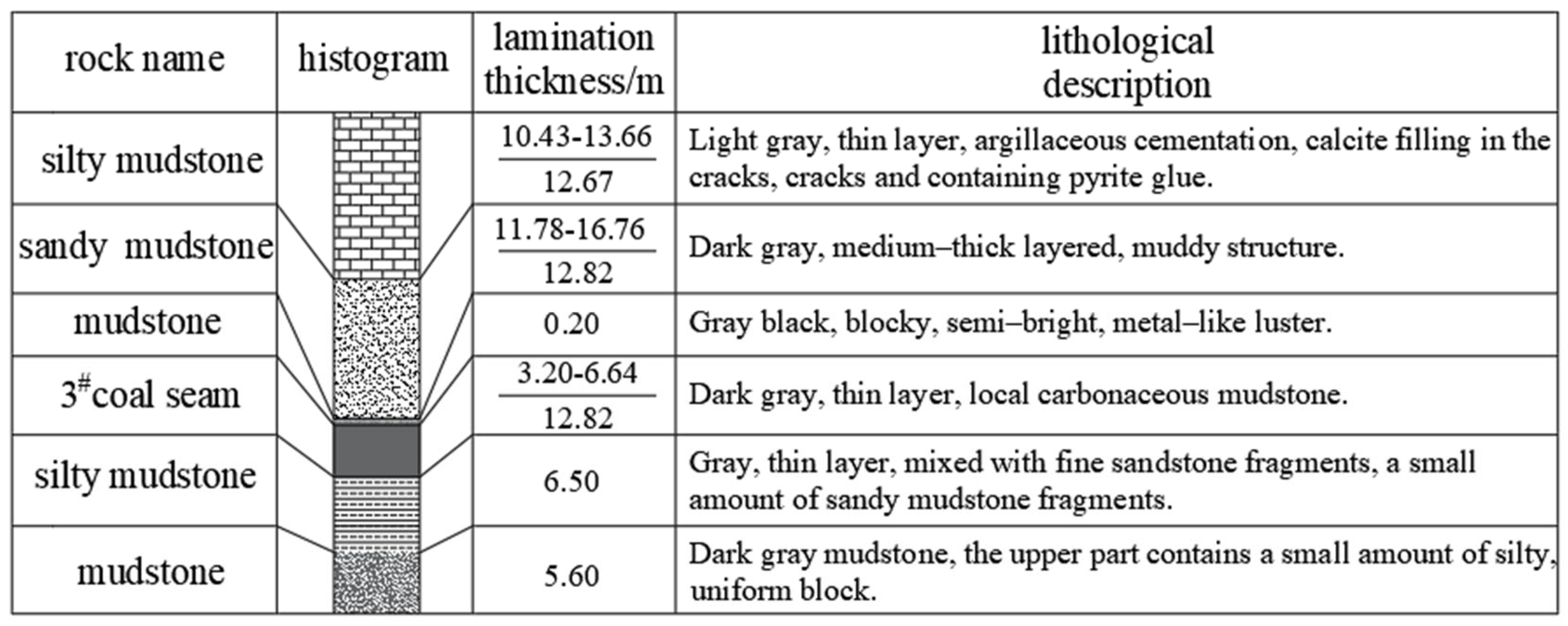
The 3# coal of the Fuyan Coal Mine adopted the single-wing sequential mining form and was excavated in two roadways, leaving 20 m coal pillars in the section. In the coal bed of the 3208 transport gateway, the buried depth was 395–443 m, with an average of 425 m; the thickness was 3.20–6.64 m, with an average of 4.81 m; the dip angle was 1–6°, with an average of 2.57°; the coal firmness coefficient was 1.09–1.2. The coal quality was soft and ductile. The immediate roof is silty mudstone, with an average thickness of 12.85 m; the immediate floor is silty mudstone, with an average thickness of 6.50 m; the main floor is carbonaceous mudstone, with an average thickness of 5.60 m. The geological conditions of the coal seam roof and floor in LW3208 are shown in Figure 1.
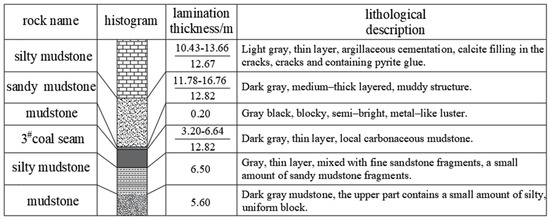
Figure 1.
Comprehensive column of coal seam roof and floor.
The designed length of the 3208 transport gateway is 836 m; the designed height of the rectangular roadway is 3.2 m; the designed width is 5.0 m. In order to reduce the adverse effect of floor heave on production, 1.6–2.0 m of coal was reserved on the roadway floor to facilitate floor lifting. Floor lifting was conducted when the working face was prepared for production, and the roadway size would become 5.0 × 5.0 m. The primary support form is the joint support of anchor bolt + anchor cable + rhombic metal mesh + reinforced beam: (1) The roof anchor bolts are MSGLW-400/20/2400 left-hand non-longitudinal rib rebar bolts. Each row has seven bolts, with a row spacing of 750 × 750 mm; the anchor bolts on both sides are 250 mm from the sidewall, with an outward inclination of 15°. The other anchor bolts are arranged perpendicular to the roof. The anchor cables are SKP-20/1860 high-strength and low-relaxation prestress steel strands, with a length of 7300 mm, and laid as 3-2-3 with a row spacing of 1500 × 1500 mm. The reinforced beams are welded with 16# round steel, with a size of 4700 × 80 mm, and either side is 100 mm from the sidewall. (2) The sidewall anchor bolts are MSGLW-400/20/2400 left-hand non-longitudinal rib rebar bolts. Each row has five bolts, with a row spacing of 700 × 750 mm. The outermost two anchor bolts are 200 mm from the roof and the floor, with an outward inclination of 15°. The other anchor bolts are arranged perpendicular to the two sidewalls. The size of the rhombus mesh is Lw10/40 × 40–850 × 5400 mm, and the lap length is 100 mm.
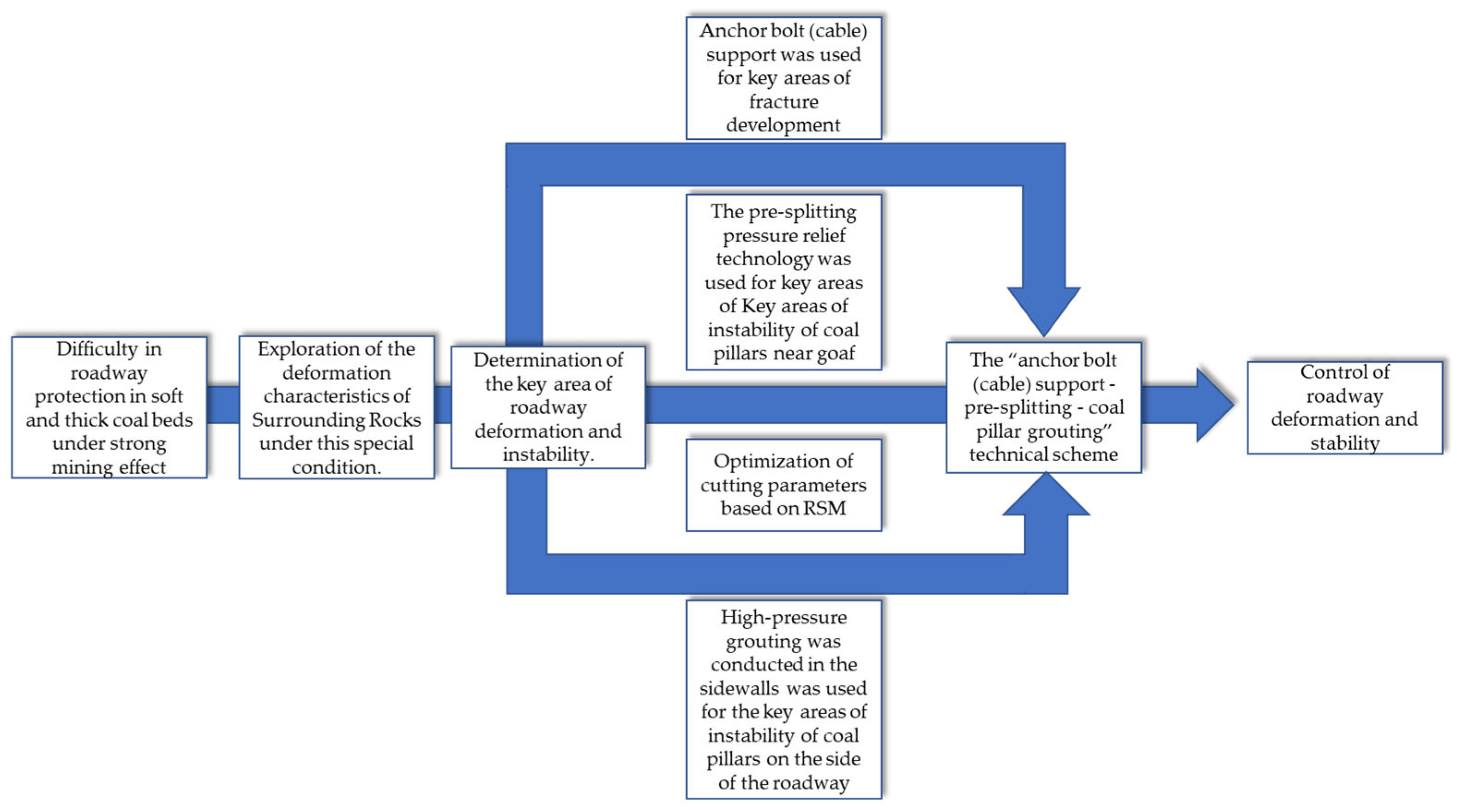
In order to solve the roadway protection problems, such as roof separation, severe floor heave, and large sidewall deformation after excavating the 3208 transport gateway in the Fuyan Coal mine, this study will follow the following process, as shown in Figure 2.
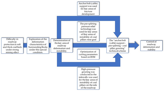
Figure 2.
Flow chart of research on multi-tech efficient coordinative roadway protection plan2.2 Characteristics of roadway deformation and failure.
The 3208 transport gateway has 1.6–2.0 m of coal on the floor; the immediate floor mainly has 6.5 m of silty mudstone. The roadway surrounding the rock is soft and ductile. After the completion of roadway excavation, with the mining of LW3208, severe floor heave and sloughing occurred in many sections of the 3208 transport gateway. After engineers conducted many repairs, the roadway was still seriously deformed, which made roadway transportation difficult and greatly restricted safe and efficient production in the working face. The deformation and failure characteristics of the roadway surrounding rock in the 3208 transport gateway are shown in Table 1.

Table 1.
Characteristics of roadway deformation on the site.
Affected by the mining advanced stresses on LW3208 and the structural movement of overlying strata on the roof, the surrounding rock in the 3208 transport gateway underwent severe deformation and failure. The deformation and failure characteristics mainly include:
(1) All sections of the roadway had various degrees of roof and floor deformation and failure. The roof sank slightly and was separated in some sections. The overall floor bulged to the inside of the roadway, with fractures in the middle. The maximum floor heave reached 1800 mm. The floor deformation squeezed the anchor bolts in the sidewalls near the floor such that the anchor bolt offset lost support.
(2) The roadway sidewalls seriously bulged within the range of 300–650 m, and the coal pillar sidewalls had severe sloughing. The roof and the sidewalls jointly squeezed into the roadway until the humeral angles were closed. As a result, the sidewall anchor bolts were seriously deformed, accompanied by nut withdrawal, loose trays, and other phenomena. The sidewalls near the floor and the bulging coal mass were squeezed, deformed, and destroyed.
(3) On the site, the roadway floor was lifted many times, which further weakened the coal pillars and floor. All the transport gateways in the area with serious floor heave were demolished, and some repaired sections showed secondary deformation. These increased operation risks and caused serious safety hazards, forming “roadway formation and failure-floor lifting and repair-further deterioration of floor coal pillars-secondary instability and failure”.
3. Stress Distribution Characteristics and Failure Mechanism of Roadway Surrounding Rocks
3.1. Equivalent Load Calculation Model of Surrounding Rock Stress Distribution
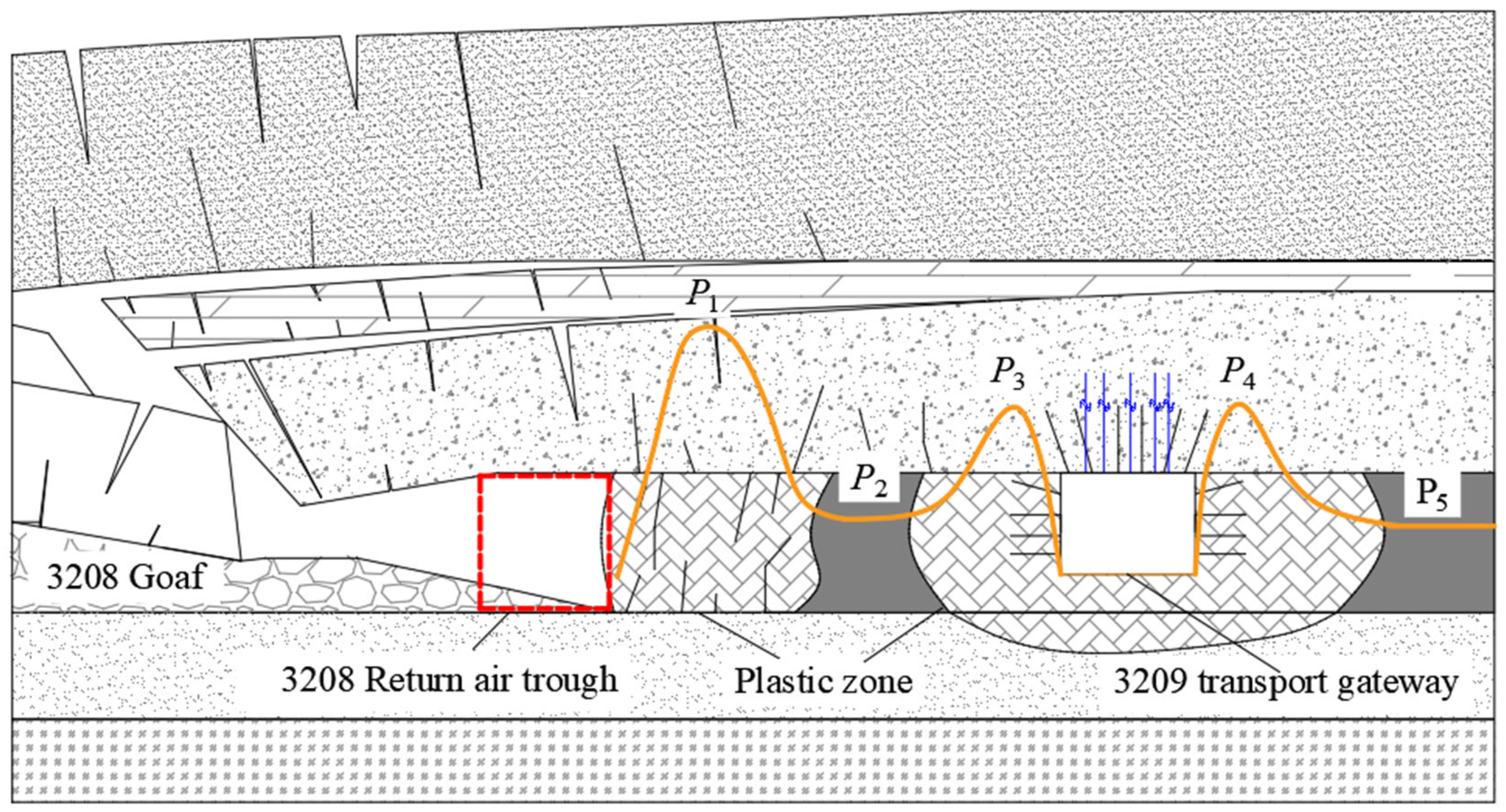
The sections with surrounding rock deformation in the 3208 transport gateway were concentrated in the pre-section of the adjacent working face and within 150 m after mining, caused by the sudden increase in bearing stress led by dynamic load and continuous high-stress concentration. In addition, the stress transfer in the overlying strata after the roadway was excavated caused stresses concentrated in the roadway sidewalls. The stress reduction caused by deformation and failure in the shallow part was also a key factor leading to roadway instability and failure [27,28]. In order to solve the problems of roadway instability and excessive deformation, we need to explore the characteristics of stress distribution in the surrounding rock and define the key areas of surrounding rock instability and deformation. The characteristics of roadway deformation and failure are shown in Figure 3.
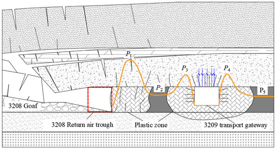
Figure 3.
Characteristics of roadway deformation and failure.
In this state, the coal mass is regarded as a continuous medium; the problem of roadway instability and deformation is regarded as a problem of semi-infinite body and a problem of plane strain in elastic-plastic mechanics. The roadway tendency model was constructed based on the elastoplastic theory. To find the solution, the changes of concentrated stresses and stress reduction are both regarded as linear changes. In the stress analysis of the coal masses in the coal pillars and roadway surrounding rocks, the influences of the dead weight of coal masses and the roadway surrounding rock on the stress reduction after roadway excavation are ignored. The surrounding rock mechanical model is constructed as shown in Figure 4.
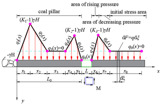
Figure 4.
Equivalent load model of roadway surrounding rock in 3208 transport gateway.
As shown in the figure, K1, K2, and K3 are the stress concentration factors of supporting pressure; H is the buried depth of the coal bed, (m); γ is the average bulk density of the strata, N/m3; x1 is the length of the section where the goaf lateral stress increases, (m); x2 is the length of the section where the goaf lateral stress decreases, (m); x3 is the length of original rock stress section, (m); x4, x7 are the lengths of sections where roadway stresses decrease, (m); x5, x6 are the lengths of sections where roadway stresses increase, (m); L is the width of the roadway, (m).
In this model, the stress expressions q1(x)–q9(x) of loads in all sections are:
A coordinate system was established with the coal pillar edge in the goaf as the origin of the coordinate. At ξ from the origin of the coordinate, a tiny length dξ was taken; the force in a tiny range near dξ is dF = q(x)dξ. The extra stress caused by the concentrated force in the roadway surrounding rock can be expressed using Formula (2):
where, is the horizontal extra stress caused by dξ at any point on the coal pillar, (MPa); is the vertical extra stress caused by dξ at any point on the coal pillar, (MPa); is the shearing extra stress caused by dξ at any point on the coal pillar (MPa).
By constructing a numerical simulation model, we could fit the bearing stresses on the roadway surrounding rock and coal pillars by section to obtain the segmental fitting function of bearing stresses. The supporting pressure increment obtained by fitting is the additional stress of the surrounding rock. After superimposing the original rock stress and additional stress at any point on the surrounding rock, we can obtain the stress state at any point on the surrounding rock:
where, is the horizontal stress at any point on the coal pillars and roadway surrounding rocks (MPa); is the vertical stress at any point on the coal pillars and roadway surrounding rocks (MPa); is the shearing stress at any point on the coal pillars and roadway surrounding rocks (Mpa); λ is the lateral pressure coefficient.
The maximum and minimum principal stresses of the coal rock mass can be expressed using Formula (4):
During the primary mining and after the mining of the working face, the outer unit of the coal pillar was in a high-stress state under biaxial compression, which was not only affected by stresses concentrated on the side of the excavation roadway but also by the pressure relief effect on the goaf side. The difference between the maximum and minimum principal stresses was large, and the roadway was in a state prone to shear and tensile failure. The depth of coal pillar failure and the deformation of the surrounding rock also increased.
3.2. Numerical Simulation of Stress Evolution Law on the Surrounding Rock in the Mining Gateway
Taking the 3208 transport gateway as the engineering background, the FLAC3D 6.0 simulation software was used to establish a numerical calculation model. It simulates the key period of roadway deformation, analyzes the deformation and stress evolution law of roadway surrounding rock, and determines the key area of roadway deformation instability. The model size is 190 × 100 × 50 m. The Mohr–Coulomb criterion is adopted. A vertical load of 10.4 Mpa is applied on the top. The physical and mechanical parameters of the coal mass are shown in Table 2.
Table 2.
Mechanical parameters of coal and rock.
This simulation focuses on the analysis of the coal pillar deformation characteristics and stress evolution law in the 3208 transport gateway. The simulated calculation steps and supporting forms are consistent with the situation on the site. When the working face was mined for 160 m, the distributions of vertical stresses and horizontal stresses on the roadway surrounding rocks are shown in Figure 5.
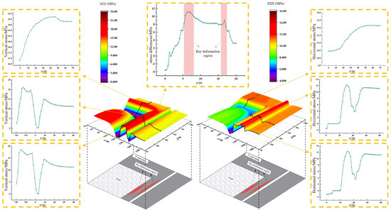
Figure 5.
Stress distribution on the working face.
(1) Within 40 m in front of the working face, two asymmetric peaks appeared among the vertical stresses on both sides of the roadway, and the bearing pressures near the working face sidewall were larger (the bearing pressures near the coal pillars and away from the coal pillars were 21.61 MPa and 19.33 MPa, respectively), which were 7.23 m and 5.65 m from the coal wall, respectively. This is because, under intense mining effects, the overlying strata collapsed and fractured; the coal mass on the goaf side was plastically damaged and extruded. As a result, the coal mass in the depth of coal pillars bore a heavier load, and the supporting pressures increased. Beyond 40 m in front of the working face, the supporting pressures were distributed symmetrically on both sides of the roadway, and the stresses at the peak points tended to be consistent;
(2) The horizontal stresses and vertical stresses show similar distribution laws. The horizontal stresses on the coal pillar sidewalls in the roadway were small, increased with the depth of coal pillars (the stress peak was 12.30 Mpa), and tended to stabilize. Under the mining effect on the working face, a peak point appeared among the horizontal stresses in the coal pillars behind the working face, which first increased and then decreased with the increase in distance from the working face.
(3) With the increase in depth in the coal pillar, the difference between the vertical stress and the horizontal stress of the coal pillar in the middle line of the roadway first increased to the peak point and then decreased until the overall trend of stability. There was a high-stress difference and two asymmetric peak points within the range of 5.14–6.29 m and 2.25–3.12 m from the coal wall, indicating that the shear capacity and bearing capacity of the surrounding rock in this area were significantly enhanced. In the shallow surrounding rock, grouting or anchoring in this area or deeper surrounding rock will effectively improve the stability of the support system, which can be regarded as the key area of roadway deformation and instability.
To sum up, in the trending direction, the advance bearing pressures were distributed in the key areas, that is, within the range 40 m ahead of the working face and the area where high stresses were concentrated behind the working face; in the dip direction, the areas where stresses were concentrated on the goaf side of coal pillars and within the range 5.65 m from the roadway sidewall. To solve the problem of roadway instability and excessive deformation, it was decided to adopt pre-splitting roof cutting based on the original anchor bolt (cable) support to realize pressure relief in the area, supplemented by grouting reinforcement with inorganic grouting materials. This reduced the impacts of advance bearing pressures and lateral bearing pressures, strengthened the roadway sidewalls, increased the bearing capacity of the coal pillars, and controlled the severe deformation of the roadway.
4. The Design of the Roadway Control Plan by Roof Cutting and Parameters Optimization
4.1. Surrounding Rock Deformation Law with the Change in Roof Cutting Parameters in Soft and Thick Coal Beds
The mining of coal beds in adjacent working faces led to large-scale migration of overlying strata. Finally, a masonry beam structure of roof strata was formed on the goaf side, and an additional stress field was formed near the roadway area, which was the section where stresses increased in Figure 3. When the coal pillars were within the influence range of this stress field, the coal masses in the roadway sidewalls would be in a high-stress state superposed by multiple stress fields.
This would lead to shear and tensile failure in the sidewalls and form spalling [29,30]. In order to reduce the adverse impact of the mining advance stresses on the goaf side of the coal pillars, roof cutting and pressure relief were conducted on the edge of the working face to cut off the stress transfer from the roof cantilever to the roadway. Then, a “short cantilever structure” was formed, which could effectively reduce the stresses on the coal masses and anchor bolt (cable) in the surrounding rocks and coal pillars in the mining roadway sidewalls and control surrounding rock deformation. The mechanical structure model of the lateral overlying strata cantilever in the goaf established is shown in Figure 6.
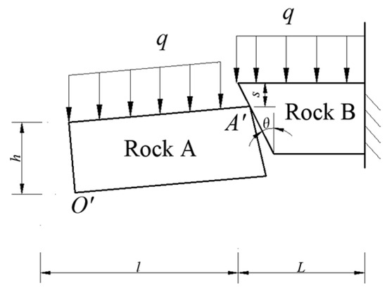
Figure 6.
Mechanical structure model of overlying strata.
In the figure, q is the average load on the immediate roof, KN/m; L is the cantilever length of the rock B, m; h is the thickness of the rock, m; s is the subsidence value of the rock A at point A′, m;
According to the voussoir beam theory and the principle of surrounding rock structural stability, when the fractured surface in the roof strata forms a certain angle with the vertical plane, the conditions for the rock to suffer sliding instability are [31,32,33]:
According to Formula (5), roof cutting is enforced on the overlying strata in the goaf, and the stability of key blocks in the coal pillars on the goaf side is related to the length of cantilever L, the angle of roof cutting , and the roof thickness hm. When the two blocks slid and became unstable, the rock on the main roof could slide along the contact surface to form a cutting roof to fully relieve pressures and obtain a good effect of roadway protection. The friction angle in the rock on the overlying strata can be taken as 22°–32°, with an average of 27°.
According to the actual engineering and geological conditions on the LW3208 transport gateway in Fuyan Coal Mine, L = 26.73 m, s = 4.55 m, hm = 13.51 m. After bringing them into Formula (5), we obtain: 6.8°. To make construction convenient, the angle of pre-splitting roof cutting is taken as 5°.
To verify the rationality of roof cutting parameters and design the optimal roof cutting scheme, different roof cutting parameters were designed for numerical calculation and simulation according to the engineering and geological conditions and construction conditions in the 3208 return airway; the displacement of roadway sidewall on the coal pillar side was taken as the representative value of roadway deformation characteristics. The stress distribution on coal pillars and sidewall displacement under each roof cutting scheme are shown in Figure 7 and Figure 8.
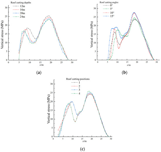
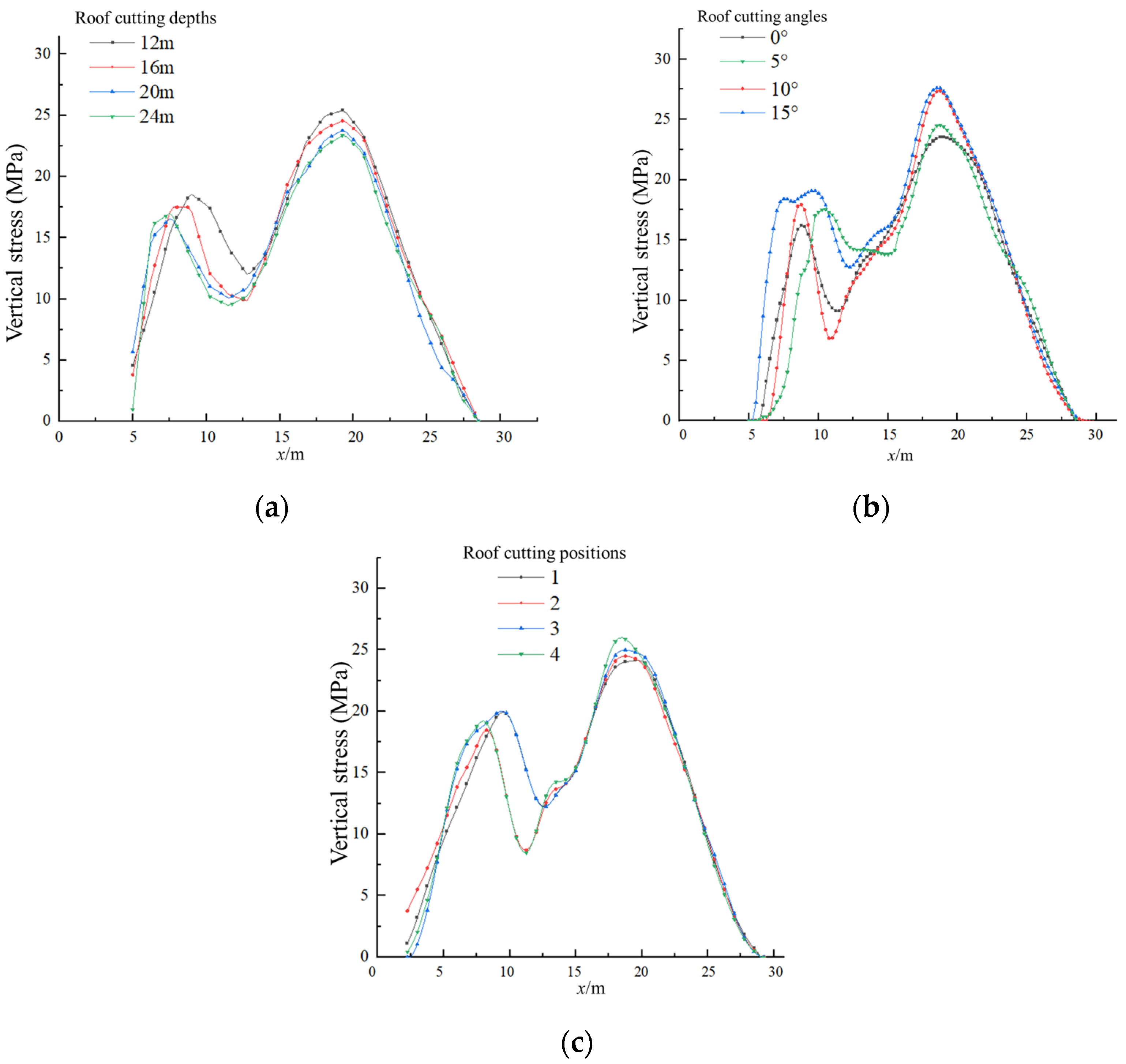
Figure 7.
Vertical stress distribution curves of coal pillars under different roof cutting parameters: (a) In different roof cutting depths; (b) at different roof cutting angles; (c) at different roof cutting positions.
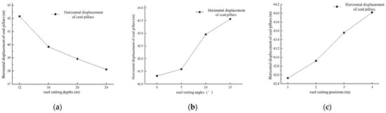
Figure 8.
Displacement variation curves of coal pillars under different roof cutting parameters: (a) In different roof cutting depths; (b) At different roof cutting angles; (c) At different roof cutting positions.
According to the above curve analysis, the changes in three roof cutting parameters will lead to changes in coal pillars and coal wall displacement to a great extent:
(1) With the increased roof cutting depth, the roadway sidewall displacement decreased. When the roof cutting depth exceeded 15 m, the displacement dropped sharply from 42.24 cm to 39.58 cm. The reason is that at this depth, the kerf completely penetrated the sandy mudstone in the immediate roof. At this moment, the pressure relief effect was good. The peak of coal pillar stresses on the goaf side decreased from 18.56 MPa to 16.98 MPa; the peak of stresses on the roadway side decreased from 25.40 MPa to 23.27 MPa, a decrease of 8.50% and 8.39%, respectively. This indicates that increasing roof cutting depth can effectively reduce stresses and surrounding rock deformation.
(2) With the increase in roof cutting angle, the roadway sidewall displacement increased. When the angle increased from 0° to 15°, the displacement increased from 41.39 cm to 43.64 cm. The reason is that when the roof cutting depth and position are fixed, the increase in roof cutting angle will lead to more loads on the cantilever from the overlying strata, and the lateral stresses will become more concentrated. The peak of coal pillar stresses on the goaf side decreased from 20.78 MPa to 18.00 MPa; the peak of stresses on the roadway side decreased from 27.92 MPa to 23.80 MPa, a decrease of 2.78% and 4.10%, respectively. This indicates that increasing the roof angle in a small scope will concentrate coal pillar stresses and increase surrounding rock deformation.
(3) With the increase in the distance from the roof cutting position to the roadway sidewall, the horizontal roadway displacement increased. As the distance increased from 1 m to 4 m, the roadway sidewall displacement increased from 42.53 cm to 44.08 cm. The reason is that when the roof cutting angle and depth were fixed, the farther the roof cutting position was from the coal wall, the larger the “cantilever length” on the roof was after roof cutting, and the more adverse impact the cantilever side of the roof had on coal pillars. The peak of coal pillar stresses on the goaf side decreased from 20.02 MPa to 18.46 MPa; the peak of stresses on the roadway side decreased from 26.00 MPa to 24.14 MPa, with a decrease of 7.79% and 7.15%, respectively. This indicates that, within a small range, increasing the distance from the roof cutting position to the coal wall can enhance the pressure relief effect and reduce surrounding rock deformation.
4.2. Experimental Design of the Deformation Response Surface in the Mining Gateway for Pre-Splitting Pressure Relief
In order to optimize the roof cutting scheme in the 3208 return airway, the Design-Expert experimental design 8.0.6 software was applied in this section. Considering the roof cutting distance, angle, and position (the distance from the pre-splitting roof cutting position to the coal wall), the simulation experiment was designed with RSM, and 13 simulation schemes were designed. As designed, the maximum roof cutting depth was 24 m, and the minimum was 12 m; the maximum roof cutting angle was 25°, and the minimum was 5°; the largest roof cutting distance was 5 m, and the smallest was 1 m; all the factors and levels were shown in Table 3.
Table 3.
Experimental factors and levels of pre-splitting and coal pillar grouting floor heave.
The analysis of orthogonal test results at 10 m ahead of the working face in the mining gateway is shown in Table 4.
Table 4.
Analysis of response surface test results.
Using the analysis function of Design Expert, we conducted multivariate regression fitting analysis on the response surface test results and obtained the correlation model between various factors for pre-splitting roof cutting and the roadway sidewall displacement:
where, A is the roof cutting depth (m), B is the roof cutting angle (°), and C is the roof cutting position (the distance between the pre-splitting roof cutting position and the coal wall) (m).
In the experiment, the coefficient of determination R2 = 0.9231 was close to 1, indicating that 92.31% change in the model response came from the selected factors. This shows that there is a small difference between the response surface and the real value; the predicted value and the measured value are highly correlated, and the test results are consistent with the practical engineering situation.
4.3. Analysis of the Influence of Changes in Roof Cutting Key Factors on Roadway Sidewall Displacement
In the variance analysis of the regression model, the lack of fit p = 0.0146, indicating that the regression result is prominent; the p values of all simulation factors are less than 0.05, indicating that the measured value and predicted value in the change in each factor fit well. The result can be used to predict and analyze the horizontal displacement in the sidewalls. The variance analysis of the regression model for sidewall horizontal displacement is shown in Table 5.
Table 5.
Variance analysis of the regression model for roadway sidewall displacement.
A scatter diagram was drawn with the horizontal displacements of all the schemes and the model fitting results. As shown in Figure 9, all the scatter plots were positioned near the fitting curve, indicating that the fitting result was good.
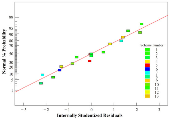
Figure 9.
Comparison between the measured value and predicted value of roadway displacement.
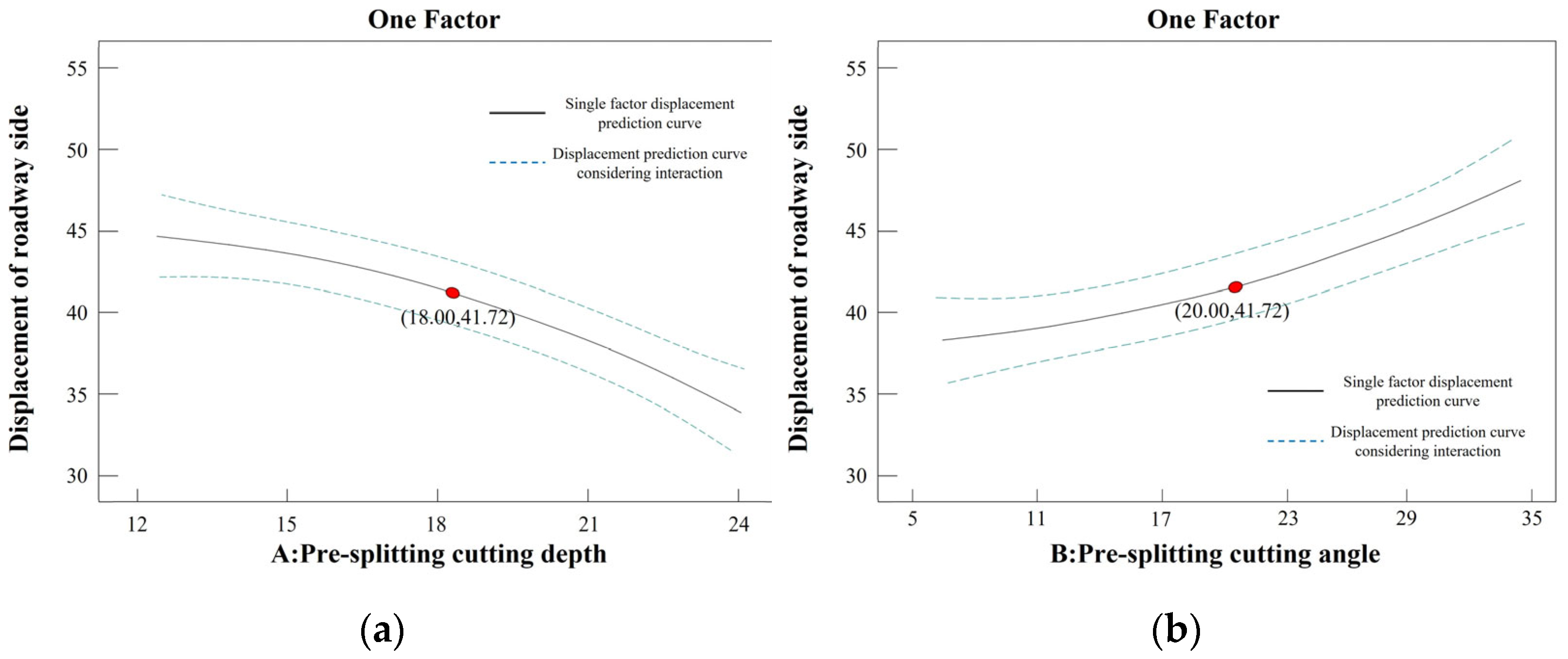
In order to study the influence law of every single factor of roof cutting on the roadway displacement, the values of all the factor levels were made into the horizontal axis, and the responses to all the factor levels, namely the roadway sidewall displacements, were made into the vertical axis. After fitting, the influence of single factors on roadway sidewall displacement is shown in Figure 10.
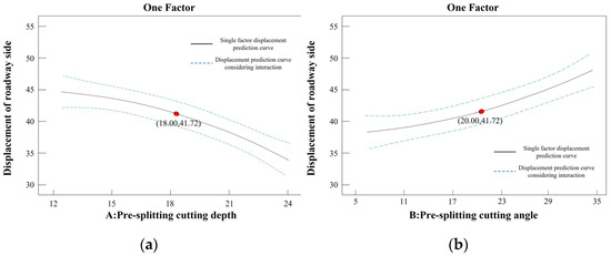
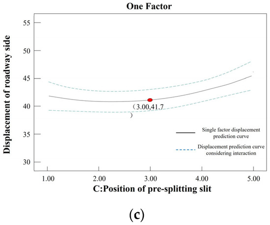
Figure 10.
Fitting curve of all the factors to roadway sidewall displacement: (a) roof cutting depth; (b) roof cutting angle; (c) roof cutting position.
According to the fitting curve, the fitting effect is consistent with the simulation effect. With the increase in roof cutting depth, the roadway sidewall displacement decreased in a negative exponential form; the sidewall displacement reached the maximum at the roof cutting depth of 12 m; the sidewall displacement reached the minimum and increased fastest at the roof cutting depth of 24 m. This is because, with the increase in roof cutting depth, the stress transmission in the overlying strata was cut off; the superposed stress on the coal pillars and surrounding rocks decreased; the sidewall displacement also decreased. With the increase in the roof cutting angle, the horizontal displacement in the roadway sidewall increased exponentially; the sidewall displacement reached the maximum at the roof cutting angle of 35°. In one aspect, when the roof cutting angle was large while the roof cutting depth was not enough to cut off the roof strata, the roof cut at the upper end could not fracture, so the pressure relief effect was greatly reduced. In another aspect, increasing the roof cutting angle was equivalent to increasing the length of the lateral cantilever on the roof so that the roof structure could not collapse but formed a new arch structure with the overlying strata. The lateral stress of coal pillars increased, so the sidewall deformation increased. With the increase in roof cutting distance, the sidewall horizontal displacement first decreased slightly and then increased rapidly. This is because when the roof cutting distance was too small, the roof near the coal pillar side squeezed with the coal pillars during the process of roof caving; some lateral stresses were re-applied on the coal pillars, so the sidewall deformation increased slightly. Then, with the increase in roof cutting distance, the cantilever length increased, the superposed stress on the sidewall increased, and the sidewall deformation increased exponentially.
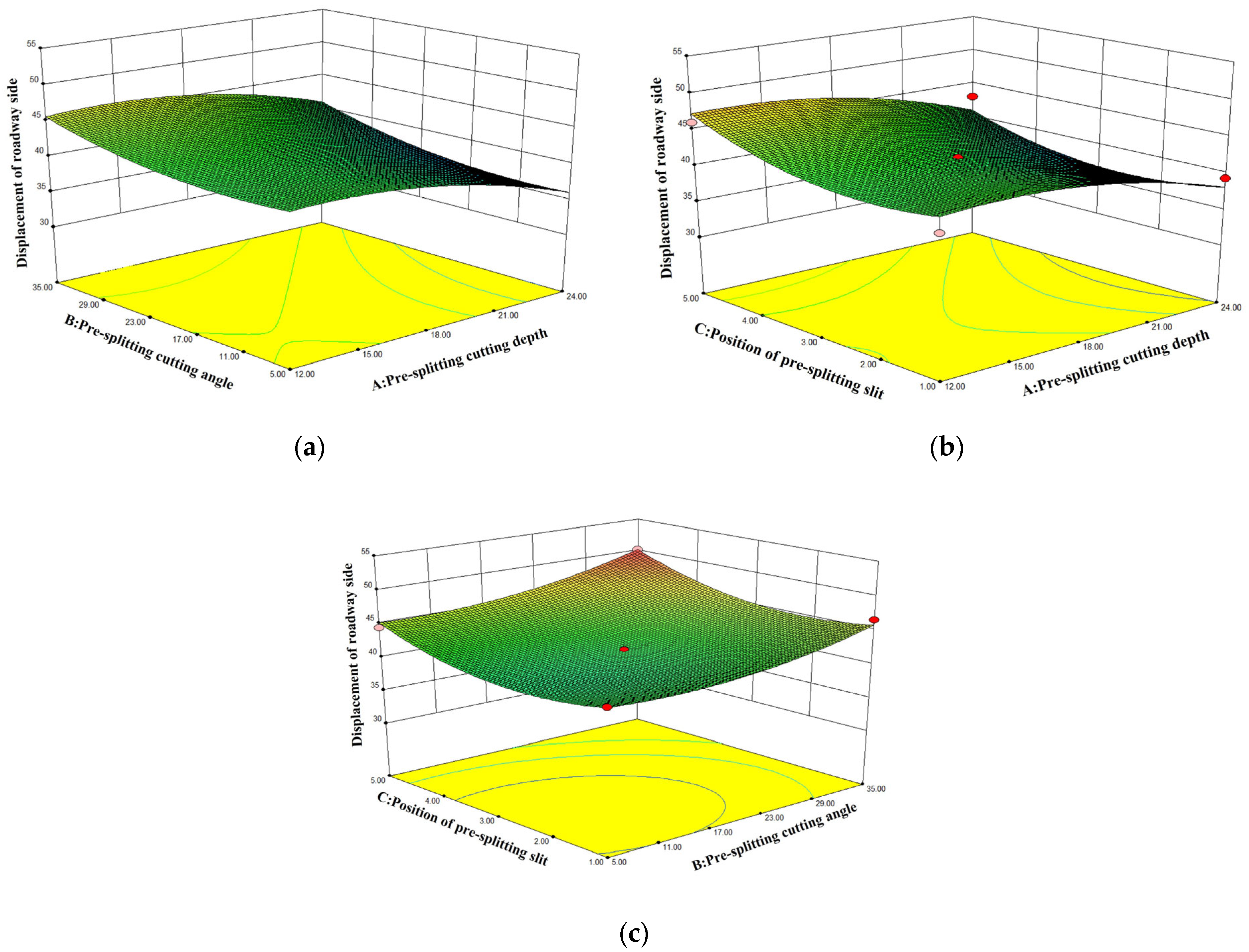
To study the influence of the law of interactions of various roof cutting factors on roadway deformation, the response surface diagram to describe the influence of various factors on the roadway sidewall displacement was established according to the regression of simulation results, as shown in Figure 11.

Figure 11.
Influence of various factors on the roadway sidewall displacement: (a) roof cutting depth and roof cutting angle; (b) roof cutting depth and roof cutting distance; (c) roof cutting angle and roof cutting distance.
In Figure 11a, the maximum sidewall displacement was influenced by single factors such as roof cutting depth, angle, and position and by the interactions of the three factors. When the roof cutting depth was fixed, the change in the response surface slowed down with the increase in the roof cutting angle. This indicates that the greater the roof cutting angle, the more difficult it was for the kerf to reach the roof and the less impact the roof cutting depth had on the sidewall displacement. The analysis shows that a small angle slit was selected as far as possible in the pre-splitting roof cutting to achieve better pressure relief effect. In Figure 11b, when the roof cutting distance was fixed, the response surface changed more significantly with the increase in roof cutting depth. This indicates that the greater the roof cutting depth, the more impact the roof cutting had on the overlying strata displacement and the more obvious changes in the coal pillar stress and sidewall displacement. In Figure 11c, with the increase in the distance from the roof cutting position to the coal pillars and the increase in the roof cutting angle, the roadway sidewall displacement increased rapidly. Under a high-stress environment, small dynamic pressure may also lead to a rapid rise of coal pillar stress and even deformation, instability, and failure. The analysis indicates that on the premise that the roof can be cut smoothly, the roof cutting position should be selected as close as possible to the coal wall. According to the fitting model, we obtained the optimal roof cutting scheme: when the roof cutting depth was 24 m, the roof cutting angle was 5.0°, and the pre-splitting kerf was 2.55 m from the coal wall. The above parameters were brought into Formula (6), and the roadway sidewall displacement was calculated as 36.96 cm. The simulation was conducted according to the fitting optimal roof cutting scheme. The simulation result was 38.35 cm, which was basically the same as the fitting result. Therefore, this scheme can be a reference in designing engineering roof cutting schemes. This scheme design method can be a reference in optimizing the design of roof cutting parameters, greatly reducing the waste of resources used for roof cutting and greatly improving the sustainability of mine energy.
5. Joint Control Technology of Roof Cutting-Grouting and Coal Pillar Instability Control Effect
Due to the soft coal quality in the 3208 transport gateway, sidewall deformation and failure easily occur. After pressure relief is taken for this roadway, it is still required to improve the engineering lithology for the sidewall soft rocks [34,35].
5.1. Mechanism of Roadway Protection by Pre-Splitting Pressure Relief and Coal Pillar Grouting Reinforcement
High-stress areas were formed in the coal pillars on the goaf side and also in the coal pillars in the roadway sidewalls affected by roadway excavation [36]. Under high-stress effects, the coal masses in the sidewalls of the soft rock roadway were destroyed. In order to maintain the roadway and reduce deformation, grouting reinforcement was adopted for the overall roadway sidewalls. The mechanism of controlling surrounding rock deformation by pre-splitting pressure relief in the mining gateway and coal pillar grouting reinforcement is shown in Figure 12.
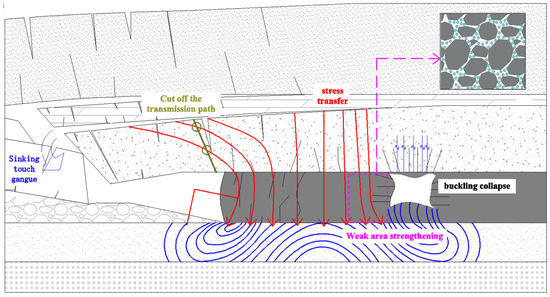
Figure 12.
Mechanism of roadway protection by pre-splitting pressure relief in the mining gateway and coal pillar grouting reinforcement.
The research above shows that during the excavation of the 3208 transport gateway, stress reduction areas appeared in the roof and floor in the middle of, in front of, and behind the working face and in the middle of the two sidewalls after the roadway was excavated; fractures in the surrounding rocks gradually spread from the shallow to the deep parts. In this stage, the fractures developed at a low degree and in a small amount. During the mining process of LW3208, due to the fracture of the overlying strata, rotary slide and extrusion deformation and failure occurred in the key block. A large number of gaps appeared in the sidewall coal masses of coal pillars in the section where the roadway was near the working face. Thus, it shows characteristics of fast successive increases in surrounding rock deformation, continuous and unstable deformation, large deformation range, and complex deformation methods. In addition, after mining LW3208, some coal walls squeezed and hinged with the main roof of the overlying strata and gangue, which led to the increase in local lateral stresses on the goaf side. The load was transferred through the coal pillars in the section to the roadway surrounding rock, placing the surrounding rock in a high-stress state superposed by multiple stress fields. The floor unit underwent tensile failure under strong unloading and high-level stresses.
The mechanism of roadway protection by pre-splitting pressure relief and coal pillar grouting reinforcement: During the roadway excavation, anchor bolt (cable) support was used for key areas of fracture development such as the roof, floor, and sidewalls. This controlled the fracture development and connected the stable bearing structure in the shallow part and the stable coal mass in the depth of the coal pillars [37,38,39]. After excavation was completed, to prevent large-scale plastic slide in the sidewall units and extrusion flow into the floor to cause extrusion floor heave, high-pressure grouting was conducted in the sidewalls [40], which refilled the fractures and fixed the cement in the destroyed rock mass. This increased the friction coefficient on the slide surface in the rock mass, and the sliding threshold on the wedge-shaped rock unit effectively controlled the coal wall fracture scope and improved the bearing capacity of roadway sidewalls, which prevented roadway instability and controlled roadway deformation. Before the working face passed the roadway section during the primary mining, the pre-splitting pressure relief technology was applied to form a lateral deep kerf in the goaf for artificially forced caving. This reduced the lateral cantilever length on the goaf side, effectively reduced the coal mass stresses and anchor bolt (cable) stresses in the shallow and deep parts of sidewalls on the coal pillar side, increased the width of the elastic core area on the coal pillars in the section, and controlled surrounding rock deformation in the coal pillar sidewalls. At the same time, single hydraulic props were used to support a certain part in front of and behind the 3208 return airway, which reduced the lateral stratum stress in the coal pillars on the goaf side and weakened the concentrated stress field of the roadway sidewall on the floor. Under the joint control of three supporting measures, the plastic zone scope of the surrounding rock could be reduced effectively, the depth of coal pillar failure was reduced, and roadway deformation was effectively controlled. The maintenance cost and repair rate of roadways were greatly reduced, which could effectively meet the requirements of mine energy sustainability.
5.2. Numerical Simulation of Prevention and Treatment of Roadway Deformation and Instability
The technical plan of preventing and treating roadway deformation and instability of “anchor bolt (cable) support-pre-splitting-coal pillar grouting” was put forward based on the above optimal roof cutting scheme obtained by the research and design of the joint roadway protection law of roof cutting pressure relief and sidewall reinforcement, and combining the engineering and geological conditions of the 3208 transport gateway and the actual situation of roadway deformation.
(1) During the excavation, a “high-strength anchor bolt (cable) + metal mesh” was used to support the roadway. The arrangement was as follows: 6 rebar bolts of Φ20 × 2400 mm were laid in each row on the roof, with the row spacing of 900 × 900 mm; the anchor bolt near the sidewall was arranged at 15° from the vertical direction; the second anchor bolt from the sidewall was arranged at 10° from the vertical direction; 5 anchor cables of Φ21.6 × 6300 mm were laid in each row. On the two sidewalls, 4 rebar bolts of Φ20 × 2400 mm were laid in each row, with a row spacing of 850 × 900 mm; the anchor bolts near the roof and the floor were arranged with a deflection of 15° from the horizontal direction; the wire mesh was supported by 12# wire.
(2) After excavation was completed, high-stress grouting reinforcement was conducted in the roadway sidewall in stages, with a grouting pressure of 6 MPa, borehole spacing of primary grouting of 1500 × 2000 mm, a distance of 5.65 m from the stress peak point to the coal wall, a designed bore depth of 6000 m, and a bore diameter of 28 mm. In the secondary grouting, three grouting holes were added in the primary grouting hole, with a hole spacing of 750 mm.
(3) During the mining in LW3208, roof cutting by shaped charge pre-splitting and blasting was conducted within 40 m in front of the 3208 return airway, with a roof cutting depth of 24,000 mm, a distance of 2500 mm from the roof cutting position to the sidewall, and arranged at 5° from the vertical director. It was determined by field test that the blasting hole spacing was 600 mm, and a three-stage emulsion explosive was adopted.
(4) Before pre-splitting roof cutting, DW45-180/110XL single prop and ‘’ type steel girder were applied to strengthen the support within 40 m in front of the 3208 return airway with a column spacing of 1000 mm.
The support arrangement of the technical plan for preventing roadway deformation and instability of “anchor bolt (cable) support-pre-splitting-coal pillar grouting” is shown in Figure 13.
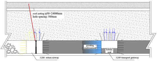
Figure 13.
Support arrangement of the “anchor bolt (cable) support-pre-splitting-coal pillar grouting” plan.
5.3. Analysis of Deformation and Failure Characteristics of Coal Pillars and Roadway Surrounding Rocks
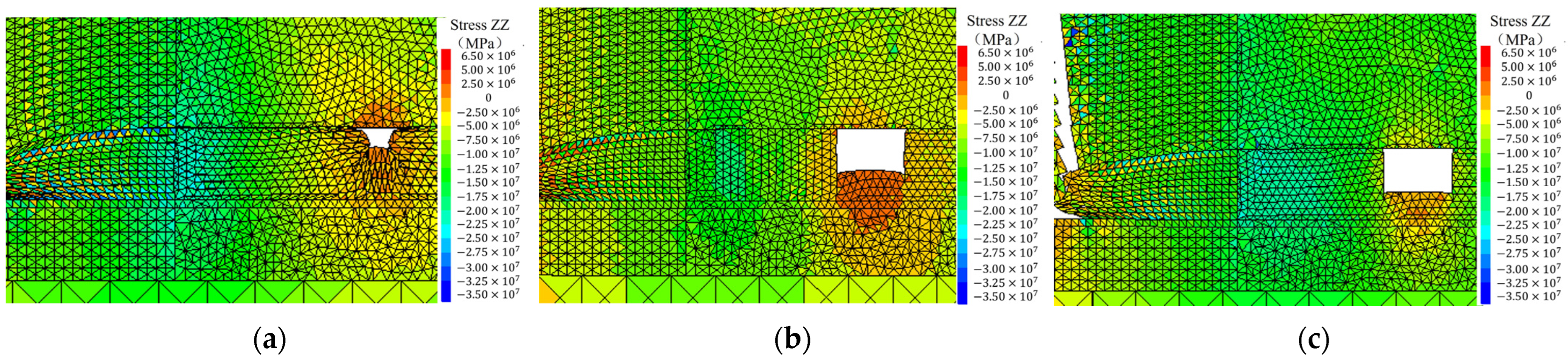
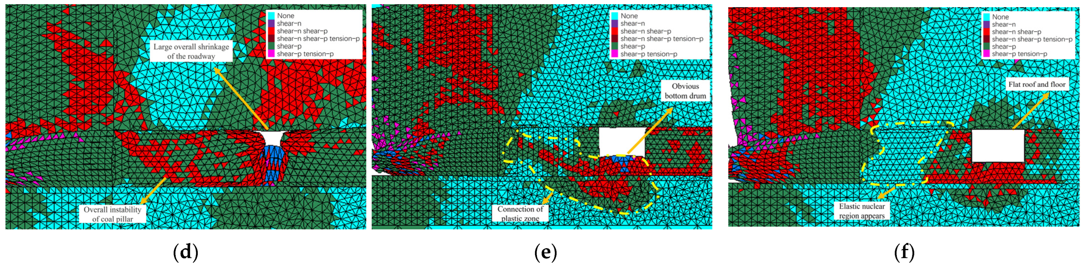
Considering the impact of fractures in the rock mass and the flow deformation of the roadway floor heave, the numerical calculation model was established using the Discrete Element Method (DEM); numerical simulation research was conducted according to the actual engineering and geological conditions in the 3208 transport gateway. According to the mining sequence in the working face, the 3208 return airway and the 3208 transport gateway were first excavated, supplemented by high-strength anchor bolt (cable) support. After grouting reinforcement in the coal wall, Working Face 3208 was excavated. Under each design scheme, the characteristics of local stress distribution and the scope of plastic zone distribution in the roadway surrounding rock, coal pillars, and overlying strata are shown in Figure 14.
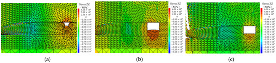
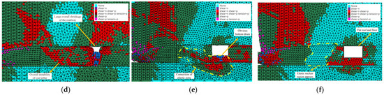
Figure 14.
Characteristics of local stress distribution and distribution of plastic zones: (a) non-support stress; (b) original anchor bolt stress; (c) roof cutting + grouting + anchor bolt stress; (d) non-support plastic zone; (e) original anchor bolt plastic zone; (f) roof cutting + grouting + anchor bolt plastic zone.
(1) With no support, the failure areas on the two side plastic zones were thoroughly connected. This indicates that the roadway was affected by roof pressure and the surrounding rock was seriously fractured. The stresses in the middle of the coal pillars were greater than the ultimate strength of the coal mass, and the stresses were distributed in an arch shape. At this time, instability and failure occurred to the coal pillars.
(2) Under the original support condition, the stress distribution characteristics were similar to those with no support. The maximum diameter of the plastic zone reached 10.28 m; the plastic zone range was reduced while it was still connected with coal pillars. This indicates that under this condition, anchor bolt (cable) support connected the shallow part and deep part of the surrounding rock, which had certain effects on controlling the roadway surrounding rock. However, the roadway remained in a high-stress state, the plastic zone development was still deep, and coal pillars had the risk of instability.
(3) After applying the technical plan to prevent and control roadway deformation and instability of “anchor bolt (cable) support-pre-splitting-coal pillar grouting,” the roof stress transfer was cut off; the roof and coal pillars reformed a strong bearing structure. Stresses in the depth of surrounding rock were greatly reduced; an elastic core area appeared; the maximum diameter of the plastic zone was reduced to 5.68 m; the maximum failure depth was greatly reduced. The rock mass strength in the sidewall on the coal pillar side increased significantly, and the deformation in the shallow surrounding rock was effectively controlled.
5.4. Analysis of Deformation and Instability Prevention and Control Effect
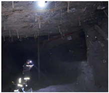
After applying the technical plan to prevent and control roadway deformation and instability in the 3208 transport gateway, we adopted the “cross-line method” to monitor the displacement of roadway floor heave, roof, floor, and two sidewalls. The results are shown in Figure 15.
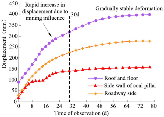
Figure 15.
Deformation of the 3208 transport gateway in field observation (75d).
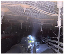
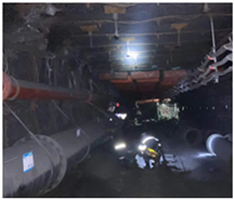
Field observation and borehole peep were conducted on sections with serious roadway deformation before and after control. The obtained on-site control effect of the roadway and the development of micro-fractures are shown in Figure 16.
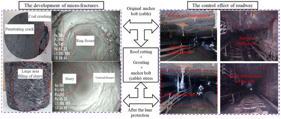
Figure 16.
Roadway field control effect and micro-fracture development.
The overall deformation and micro crack development of the tunnel before and after the implementation of the tunnel protection plan are shown in Figure 16. Sample tests were carried out on the sidewalls before and after grouting. The compressive strength of grouting coal samples was 9.86 MPa, 63.7% higher than before grouting. The tensile strength of grouting coal samples was 2.06 MPa, 63.4% higher than before grouting. According to the borehole peep at the sampling position, the reduction of coal rock fractures was decreased by 53.72% and 26.15%, respectively, compared with those before grouting and under original support conditions. The cement slurry effectively filled the fractures and joints in the coal rock, bonded fractured coal rocks into a whole, and maintained the integrity of coal pillars. Within 30 days after adopting the prevention and control technology of roadway deformation and instability, the deformation of the roof, floor, and sidewalls increased rapidly and then slowed down. The roadway floor heave, roof and floor displacement, and the displacement of two sidewalls were respectively 354 mm, 292 mm, and 483 mm. Floor heave accounted for 23.4% of the roof and floor displacement. Through field monitoring, overall roadway deformation, roof separation, and anchor bolt (cable) stresses were all within a controllable range. To sum up, the technical plan to prevent and control roadway deformation and instability effectively controlled sidewall deformation and floor heave so that the roadway met the requirement for sustainable production.
6. Discussion
Roadway protection in soft and thick coal beds under strong mining effects is a complicated engineering problem. Before preparing the technical scheme, we conducted several field investigations, established the equivalent load calculation model of stress distribution in roadway surrounding rocks, and defined the key areas of roadway deformation and instability. Based on the experimental design and data analysis with the Response Surface Method (RSM), the optimal cutting parameters that meet the design requirements were ultimately defined. The characteristics of surrounding rock deformation in the roadway were monitored throughout the process to verify the feasibility of the technical scheme. The “anchor bolt (cable) support-pre-splitting-coal pillar grouting” scheme is finally obtained through a series of works mentioned above.
The roadway is buried deep, the immediate roof is thick, and the rock pressure is not obvious. Even in the same mine, the surrounding rock structure changes a lot and has different characteristics. The technical scheme still needs to be updated to meet the energy sustainability requirements of different mines. It considers the establishment of the model from the view of the main roof more than the influence of LW3208 and the support resistance of the hydraulic support. The monitoring results show that the roadway deformation is as expected. If the surrounding rock control theory is optimized, the simulation effect of the equivalent load calculation model can be closer to the actual engineering situation, the error can even be fixed within a certain range, and the utilization rate of mine resources can be improved. Therefore, more relevant practices and research are needed in the future to achieve the sustainable development of mine resources.
7. Conclusions
(1) Considering the numerical simulation results, two key areas in the coal pillar are identified, in which the susceptibility and possibility of shear slip failure of surrounding rocks might increase. And the key is to take pressure relief or reinforcement measures in these two areas.
(2) The results of numerical simulation show that within a small range, the changes of all three factors significantly impact the pressure relief effect in the roadway, which qualitatively verified the degree and regularity of the influence of various factors on the roadway deformation.
(3) Both the RSM analysis and U-DEC simulation results show that the sidewall displacement changes with different single roof cutting parameters, and there are interactions between various parameters. In situ application results show that the roadway deformation with the optimal scheme is well controlled compared to that in the original supporting scheme.
(4) The roadway protection mechanism with “anchor bolt (cable) support-presplitting-grouting” technology was revealed. With the application of this technology, the fracture number in the roadway sidewall on the coal pillar side was greatly suppressed, and the integrity of the surrounding rock was significantly improved.
Author Contributions
Conceptualization, X.Z. and F.W.; methodology, X.Z.; software, H.Q.; validation, X.Z., F.W. and H.Q.; formal analysis, C.L.; investigation, Z.L.; resources, F.W.; data curation, C.L.; writing—original draft preparation, X.Z.; writing—review and editing, H.Q.; visualization, H.Q.; supervision, C.L. and W.H.; project administration, H.Q.; funding acquisition, F.W. All authors have read and agreed to the published version of the manuscript.
Funding
This paper was supported by “the Fundamental Research Funds for the Central Universities (2023ZDPY03)”.
Institutional Review Board Statement
Not applicable.
Informed Consent Statement
Not applicable.
Data Availability Statement
Not applicable.
Conflicts of Interest
The authors declare no conflict of interest.
References
- Kang, H.; Yin, K. Simulation study on dilatant and rheologic properties of soft rocks surrounding deep roadway and its application. Mei T’an Hsueh Pao J. China Coal Soc. 2023, 48, 15–33. [Google Scholar] [CrossRef]
- Sun, Y.; Li, G.; Zhang, J.; Xu, J. Failure mechanisms of rheological coal roadway. Sustainability 2020, 12, 2885. [Google Scholar] [CrossRef]
- Lin, W.; Cheng, J.; Li, D.; Dang, H. Deformation characteristics and control technology of roadway in water-rich soft rock. Geofluids 2022, 2022, 2234334. [Google Scholar] [CrossRef]
- Cai, J.; Tu, M.; Zhang, H. Deformation and instability mechanism and control technology of mining gateway for Jurassic weak-cemented soft rock roadways. J. Min. Saf. Eng. 2020, 37, 1114–1122. [Google Scholar] [CrossRef]
- Liu, S.; Bai, J.; Wang, X.; Yan, S.; Zhao, J. Field and numerical study on deformation and failure characteristics of deep high-stress main roadway in Dongpang Coal Mine. Sustainability 2021, 13, 8507. [Google Scholar] [CrossRef]
- Zhao, B.; Wang, F.; Liang, N.; Wang, W. Reasonable segment pillar width and its control technology for fully mechanized top-coal caving face with high stress. J. Min. Saf. Eng. 2018, 35, 19–26. [Google Scholar] [CrossRef]
- Guo, Y.; Zheng, X.; Guo, G.; Zhao, Q.; Zhou, W.; An, T. Study on deformation failure and control of surrounding rock in soft rock roadway in close range coal seam with overhead mining. J. Min. Saf. Eng. 2018, 35, 1142–1149. [Google Scholar] [CrossRef]
- Ju, J.; Xu, J.; Wang, Q. Cantilever structure moving type of key strata and its influence on ground pressure in large mining height workface. J. China Coal Soc. 2011, 36, 2115–2120. [Google Scholar] [CrossRef]
- Wang, K.; Xing, K.; Fan, L.; Yang, G.; Zou, Y.; Jiang, J. Study on numerical simulation of strata-pressure behaviors in fully-mechanized caving face. China Energy Environ. Prot. 2020, 42, 170–174. [Google Scholar] [CrossRef]
- Lian, X.; Li, C.; Li, J.; Wu, L. Law of strata pressure behavior of surrounding rock in nearby goaf roadway for extra-thick coal seams of Datong Mine Area. Front. Earth Sci. 2023, 10, 1015378. [Google Scholar] [CrossRef]
- Wang, H.; Li, S.; Li, W.; Li, H.; Li, Z. Failure mechanism of roadway surrounding rock in deep thick coal seam and its support optimization. J. Min. Saf. Eng. 2012, 29, 631–636. [Google Scholar]
- Kang, H.; Lin, J.; Wu, Y. High pretensioned stress and intensive cable bolting technology setinfull section and application in entry affected by dynamic pressure. Mei T’an Hsueh Pao J. China Coal Soc. 2009, 34, 1153–1159. [Google Scholar]
- He, M.; Wang, Y.; Yang, J.; Zhou, P.; Gao, Q. Comparative analysis on stress field distributions in roof cutting nonpillar mining method and conventional mining method. J. China Coal Soc. 2018, 43, 626–637. [Google Scholar] [CrossRef]
- Sun, Q.; Ma, F.; Guo, J.; Li, G.; Feng, X. Deformation failure mechanism of deep vertical shaft in Jinchuan Mining Area. Sustainability 2020, 12, 2226. [Google Scholar] [CrossRef]
- Wang, X.; Zhang, Y.; Zhang, Q.; Wei, Y.; Liu, W.; Jiang, T. Space-time evolution characteristics of deformation and failure of surrounding rock in deep soft rock roadway. Sustainability 2022, 14, 12587. [Google Scholar] [CrossRef]
- Tian, C.; Liu, Y.; Lou, H.; Jia, T. Stability Control of a Roadway Surrounding Rock during the Cutting and Pressure Relief of a Coal-Bearing Roof at a Shallow Mining Depth. Geofluids 2022, 2022, 5308530. [Google Scholar] [CrossRef]
- Cheng, L.; Xu, J.; Lu, T. Effects of Tectonic Stress on Stability of Dilatancy Characteristic Soft Rock Roadway Intersection in Deep Underground. Disaster Adv. 2012, 5, 1190–1195. [Google Scholar]
- Zhan, Q.; Zheng, X.; Du, J.; Xiao, T. Coupling instability mechanism and joint control technology of soft-rock roadway with a buried depth of 1336 m. Rock Mech. Rock Eng. 2020, 53, 2233–2248. [Google Scholar] [CrossRef]
- Kang, H.; Lin, J.; Fan, M.J. Investigation on Support pattern of a coal mine roadway within soft rocks—A case study. Int. J. Coal Geol. 2015, 140, 31–40. [Google Scholar] [CrossRef]
- Kang, H.; Feng, Z. Status and development tendency of roadway grunting reinforcement technology in coal mine. J. Min. Strat. Control Eng. 2013, 18, 1–7. [Google Scholar] [CrossRef]
- Sun, Y.; Li, G.; Zhang, J.; Sun, J.; Huang, J.; Taherdangkoo, R. New insights of grouting in coal mass: From small-scale experiments to microstructures. Sustainability 2021, 13, 9315. [Google Scholar] [CrossRef]
- Ma, X.; He, M.; Li, X.; Wang, E.; Hu, C.; Gao, R. Deformation mechanism and control measures of overlying strata with gob-side entry retaining formed by roof cutting and pressure releasing. J. Min. Saf. Eng. 2019, 48, 474–483. [Google Scholar] [CrossRef]
- Yang, H.; Zhang, N.; Han, C.; Sun, C.; Song, G.; Sun, Y.; Sun, K. Stability control of deep coal roadway under the pressure relief effect of adjacent roadway with large deformation: A case study. Sustainability 2021, 13, 4412. [Google Scholar] [CrossRef]
- Chi, B.; Zhou, K.; He, M.; Yang, J.; Wang, Q.; Ma, X. Optimization research on supporting parameters of roof cutting entry retaining with large mining height face. Meitan Kexue Jishu 2017, 45, 128–133. [Google Scholar] [CrossRef]
- Chen, S.; Guo, Z.; Ma, Z.; Hu, J.; Wang, J.; Zhu, S.; Zhang, M. Research on parameters optimization of cumulative blasting used in cutting roof in Chengjiao Coal Mine. Coal Technol. 2016, 35, 17–19. [Google Scholar] [CrossRef]
- Fan, D.; Liu, X.; Tan, Y.; Song, S.; Gu, Q.; Yan, L.; Xu, Q. Roof cutting parameters design for gob-side entry in deep coal mine: A case study. Energies 2019, 12, 2032. [Google Scholar] [CrossRef]
- Xi, P.; Zhu, D.; Huo, Y.; Xing, C.; Wang, Z. Numerical investigation of the failure mechanism and countermeasures of the roadway surrounding rockmass within deep soft rock. Int. J. Multiscale Comput. Eng. 2022, 20, 17–41. [Google Scholar] [CrossRef]
- Yang, S.-Q.; Chen, M.; Jing, H.-W.; Chen, K.-F.; Meng, B. A case study on large deformation failure mechanism of deep soft rock roadway in Xin’An Coal Mine, China. Eng. Geol. 2017, 217, 89–101. [Google Scholar] [CrossRef]
- Yang, H.; Li, Y.; Liu, Y.; Cao, S.; Pan, R.; Wang, H.; Wang, B.; Chen, X.; Zhao, X. Structure evolution and stability control mechanism of hard-roof cutting for roadway retaining. J. Min. Saf. Eng. 2021, 38, 766–773. [Google Scholar] [CrossRef]
- Gao, M. Study on surrounding rock control technology of gob-side entry of cutting roof for compound roof in soft coal seam. Coal Technol. 2021, 40, 41–45. [Google Scholar] [CrossRef]
- Li, Y.; Hua, X.; Cai, R. Mechanics Analysis on the stability of key block in the gob-side entry retaining and engineering application. J. Min. Saf. Eng. 2012, 29, 357–364. [Google Scholar]
- Chen, S.; Zhao, F.; Wang, H.; Yuan, G.; Guo, Z.; Yang, J. Determination of key parameters of gob-side entry retaining by cutting roof and its application to a deep mine. Rock Soil Mech. 2019, 40, 332–342+350. [Google Scholar] [CrossRef]
- Yang, Z.; Ding, Y.; Gao, X. Experimental study on mechanical response failure mechanism of dynamic pressure roadway based on roof cutting and pressure releasing technology. Saf. Coal Mines 2021, 52, 47–53. [Google Scholar] [CrossRef]
- Kikumoto, M.; Vu, P.Q.N.; Yasuhara, H.; Kishida, K. Constitutive Model for Soft Rocks Considering Structural Healing and Decay Structural Healing. Comput. Geotech. 2017, 91, 93–103. [Google Scholar] [CrossRef]
- Pan, Y.; Zhang, H.; Hao, Z.; Zhang, G.; Chen, S.; Wang, L. Engineering Properties of Soft Rock with High Geostress and the Performance Under Excavation of Deep Tunnel. Arab. J. Sci. Eng. 2022, 47, 13349–13364. [Google Scholar] [CrossRef]
- Zhang, B.; Wang, H.; Wang, P.; Yu, G.; Gu, S. Experimental and theoretical study on the dynamic effective stress of loaded gassy coal during gas release. Int. J. Min. Sci. Technol. 2023, 33, 339–349. [Google Scholar] [CrossRef]
- Chen, Y.; Teng, J.; Bin Sadiq, R.A.; Zhang, K. Experimental Study of Bolt-Anchoring Mechanism for Bedded Rock Mass. Int. J. Geomech. 2020, 20, 04020019. [Google Scholar] [CrossRef]
- Yuan, W.; Hong, K.; Liu, R.; Ji, L.; Meng, L. Numerical simulation of coupling support for high-stress fractured soft rock roadway in deep mine. Adv. Civ. Eng. 2022, 2022, 7221168. [Google Scholar] [CrossRef]
- Zhang, H.; Li, Y.; Wang, X.; Yu, S.; Wang, Y. Study on Stability Control Mechanism of Deep Soft Rock Roadway and Active Support Technology of Bolt-Grouting Flexible Bolt. Minerals 2023, 13, 409. [Google Scholar] [CrossRef]
- Jing, W.; Liu, S.; Yang, R.; Jing, L.; Xue, W. Mechanism of aging deformation zoning of surrounding rock in deep high stress soft rock roadway based on rock creep characteristics. J. Appl. Geophys. 2022, 202, 104632. [Google Scholar] [CrossRef]


Disclaimer/Publisher’s Note: The statements, opinions and data contained in all publications are solely those of the individual author(s) and contributor(s) and not of MDPI and/or the editor(s). MDPI and/or the editor(s) disclaim responsibility for any injury to people or property resulting from any ideas, methods, instructions or products referred to in the content. |
© 2023 by the authors. Licensee MDPI, Basel, Switzerland. This article is an open access article distributed under the terms and conditions of the Creative Commons Attribution (CC BY) license (https://creativecommons.org/licenses/by/4.0/).