Technical Note

A Novel Three-Dimensional Composite Isolation Bearing and Its Application to the Mitigation of Earthquakes and Traffic-Induced Vibrations

1
Key Laboratory of Earthquake Engineering and Engineering Vibration, Institute of Engineering Mechanics, China Earthquake Administration, Harbin 150080, China
2
School of Civil Engineering and Architecture, Wuhan Institute of Technology, Wuhan 430073, China
*
Authors to whom correspondence should be addressed.
Sustainability 2023, 15(23), 16374; https://doi.org/10.3390/su152316374
Submission received: 5 November 2023 / Accepted: 24 November 2023 / Published: 28 November 2023

Abstract

:
Potential damage caused by earthquakes combined with reduced comfort due to traffic has become a big challenge when designing modern buildings, and base-isolation is one of the most effective solutions to such a problem. However, most isolation bearings cannot provide sufficient mitigation for both earthquakes and traffic-induced vibrations simultaneously. To this end, this research proposes a new type of three-dimensional isolation bearing for the mitigation of both earthquake effects and traffic-induced vibrations, which is composited by a thick rubber bearing, an auto-reset flat sliding bearing, and a double concave friction pendulum bearing. In this study, the analytical hysteresis model of the proposed isolation bearing was derived and experimentally validated. In addition, the fatigue performance and vertical compression performance of the proposed isolation bearing was tested and analyzed. Finally, the mitigation effect for traffic-induced vibrations of the proposed isolation bearing was validated through a field test.

1. Background

The conventional, performance-based seismic design of buildings mainly considers the ductility and energy consumption of structural members, which ensures that the structure will not collapse after an earthquake. However, such a design does not guarantee that the building can remain damage-free after one or more disasters, and considerable economic loss is possible [1]. Evidently, such a design method would result in considerable economic losses due to corresponding repair work. Therefore, lots of newly built buildings embrace the concept of sustainable seismic design, which not only guarantees structural safety but also allows the structure to be quickly recovered [2,3]. On the other hand, due to the rapid development of transportation networks, reduced human comfort caused by traffic has now become a serious problem in the design of modern buildings [4]. A solution both sustainable seismic design and reduced comfort due to traffic-induced vibrations is vibration isolation, which can be realized by technologies such as self-centering, dampers, base-isolation, etc. [5,6]. Among these available solutions, base-isolations are reported to have satisfactory vibration mitigation performances and reasonable prices, and isolation bearings are the most widely used equipment for base-isolations [7].
The most widely used isolation bearings are sliding bearings (SBs) and elastomeric bearings (EBs) [8]. SBs can be roughly classified into curved surface sliding bearings (CSSBs), such as friction pendulum bearings (FPBs), and flat surface sliding bearings (FSSBs), depending on the curvature of the bearing’s surface [9,10]. It is noted that SBs are good at isolating horizontal vibrations but have nearly no effect on vertical vibrations [11] and therefore apparently cannot be applied to mitigate traffic-induced vibrations. Also, the use of SBs often leads to displacement excursions and corresponding maintenance problems. Hence, double concave friction pendulum bearings (DCFPBs) and auto-reset flat slider bearings (ARFSBs) were invented, both of which can automatically recover their original states after undergoing vibrations [12,13]. Recently, textured sliding bearings (TSBs) were developed in order to achieve better performance [14].
In contrast to SBs, EBs can mitigate 3-dimensional (3D) vibrations (i.e., vibrations that contain both horizontal and vertical components). EBs are mainly divided into the following two categories: steel-reinforced elastomeric bearings (SREBs) and fiber-reinforced elastomeric bearings (FREBs). Of the two, SREBs have found much more use than FREBs [15]. SREBs can be further distinguished in the following subcategories: low-damping rubber bearings (LDRBs) [16], high-damping rubber bearings (HDRBs) [8], and lead-rubber bearings (LRBs) [17]. Nevertheless, a recent study on the biaxial hysteretic behaviors of FREBs sheds light on the promising engineering applications of these bearings in the future [18]. At this junction, it is noted that the EBs that are designed for earthquakes are usually not applicable to traffic-induced vibrations because seismic ground motions and traffic-induced vibrations are quite different in terms of frequency (i.e., the dominant frequencies of earthquakes are much lower than those of traffic-induced vibrations), and the mitigation effect of EBs heavily depends on the frequency.
On the other hand, because human comfort is sensitive to the vertical components of traffic-induced vibrations, EBs rather than SBs are used to deal with traffic-induced vibrations, of which thick rubber bearings (TRBs) are reported to have satisfactory isolation effects [19]. TRBs can be regarded as elongated LDRBs, whose working frequency range is modified according to the frequency distribution of traffic-induced vibration. For decades, the use of TRBs to deal with traffic-induced vibrations has been extensively studied. Pan et al. studied the attenuation effects of TRBs on the vibrations caused by rail trains through experimental tests [20]. Zhang et al. studied the attenuation effect of TRBs on the vibrations caused by rail trains [21]. Sheng et al. investigated the effect of TRBs on the vibrations caused by metro trains through in situ experiments and semi-analytical models. [22]. Kikuchi and Aiken analyzed the hysteretic behavior of TRBs [23]. However, TRBs cannot efficiently handle earthquakes for the following two reasons: (1) their working frequency range is designed for traffic-induced vibrations, while the dominant frequencies of earthquakes are out of their range; and (2) TRBs tend to lose stability during earthquakes due to their longer sizes. Recently, various new base-isolation technologies for traffic-induced vibrations have emerged, such as geogrids [24], air cushions [25], and wave barriers [26], etc.
As discussed above, TRBs can effectively deal with traffic-induced vibration but are ineffective against seismic ground motions, while other types of bearings cannot effectively deal with traffic-induced vertical vibrations. It is difficult for the current isolation bearings to simultaneously attenuate both earthquake and traffic-induced vibrations [27]. Therefore, it is urgent to propose a new type of 3D vibration isolation bearing that can effectively block the horizontal vibrations caused by earthquakes and vertical vibrations caused by traffic. One viable way to achieve such a goal is to decompose vertical vibration components from horizontal ones through the combination of different types of bearings. Based on this idea, this paper proposes a new type of 3D isolation bearing for the mitigation of both earthquake and traffic-induced vibrations, an isolation bearing which consists of a TRB, an ARFSB, and a DCFPB. The proposed isolation bearing decouples vertical vibrations from horizontal vibrations and achieves the effect of effectively blocking 3D vibrations. On one hand, the proposed isolation bearing isolates the horizontal vibrations by cooperating with both the ARFSB and the DCFPB, which also provide sufficient stability for the TRB. On the other hand, the TRB can effectively attenuate traffic-induced vertical vibrations. The proposed isolation bearing is rate-dependent because the friction coefficients of the ARFSB and the DCFPB depend on the relative velocity of the contacted surfaces. Such a rate-dependent property of the proposed isolation bearing is beneficial for mitigating the effects of higher-frequency vibrations because the friction coefficients of the ARFSB and the DCFPB monotonically increase as the rate increases.
The rest of this paper is structured as follows: Section 2 introduces the design and mechanism of the proposed isolation bearings, Section 3 analyzes the mechanical properties of the proposed isolation bearings, and Section 4 validates the attenuation effects ontraffic-induced vibrations of the proposed isolation bearings via field tests.

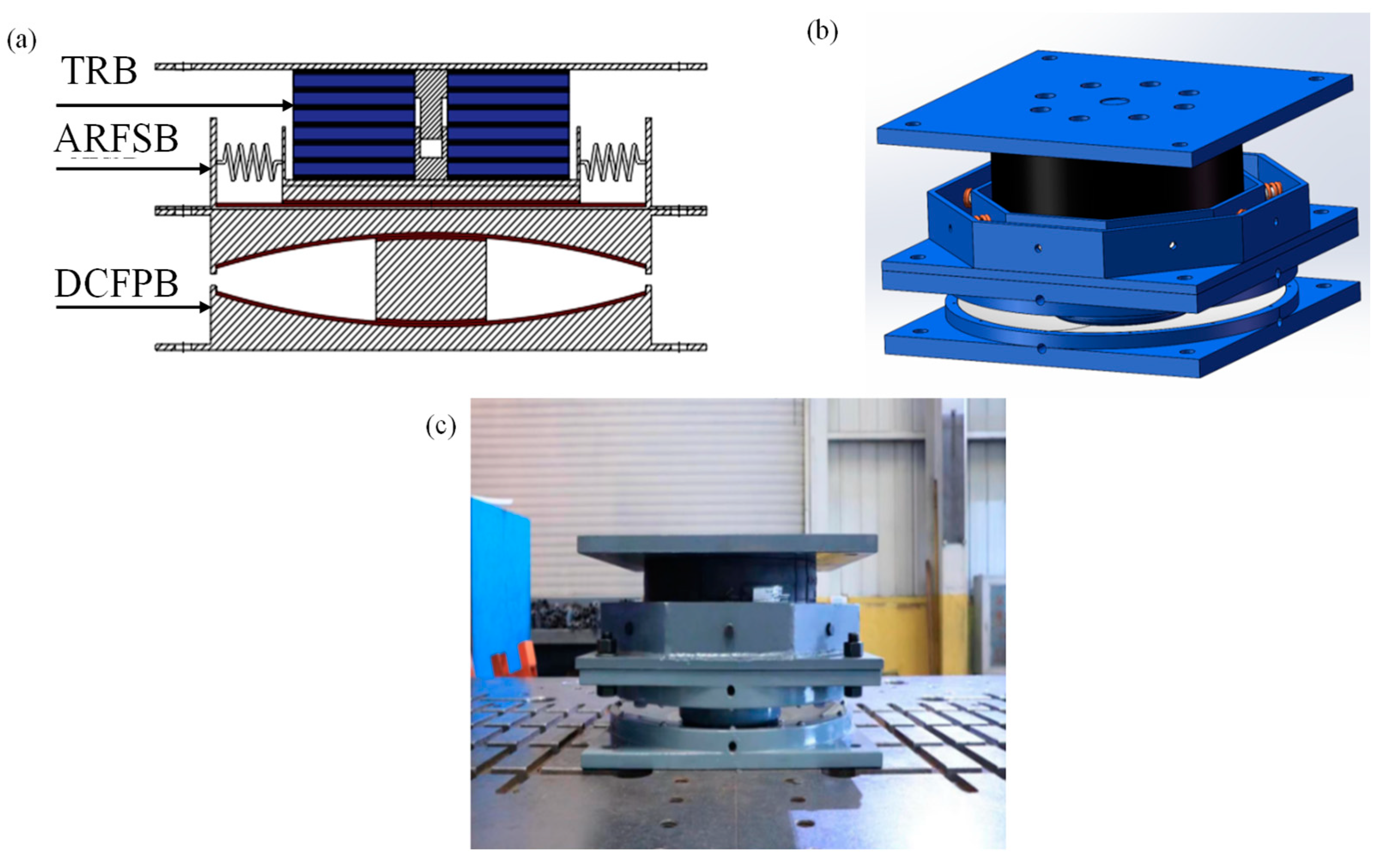
2. Design and Mechanism

The isolation bearing proposed in this paper is composed of the following three parts: a TRB, an ARFSB, and a DCFPB (as shown in Figure 1). The TRB is a T-LNR400 TRB with three layers of steel plate and four layers of rubber, which is manufactured by Zhen’an Technology Co., Ltd., Kunming, China. Its the total weight is 58 kg and the thickness of the rubber layer and the steel plate are 15.5 mm and 3.5 mm, respectively. The model number of the DCFPB is FPS-II-1000-300, which is manufactured by Zhen’an Technology Co., Ltd., Kunming, China. Its total weight is 236 kg, the radius of the sliding surface is 2.7 m, the maximum sliding angle is 6.5 degrees, and the maximum displacement is 300 mm. The ARFSB’s model number is ESB400; its total weight is 143 kg and the equivalent stiffness of its springs is 40 kN/m.
In the proposed isolation bearing, the ARFSB adopts the form of a cylinder sleeve, and the TRB is fixed on the sleeve. The DCFPB is installed under the ARFSB. Both sleeves are arranged in an octagonal shape and are connected by eight springs, which ensure that the slider at the bottom of the sleeve slides can auto-reset after deformations. The horizontal vibration isolation system of the proposed isolation bearing is composed of the ARFSB and the DCFPB. These two bearings have different horizontal equivalent stiffnesses, sliding forces, and natural vibration periods. The mitigation effect for vertical vibrations is mainly provided by the TRB. It is seen that the proposed isolation bearing can realize 3D vibration mitigations due to the fact that the TRB only undergoes vertical vibrations because the octagonal center tube prevents horizontal deformation of the TRB under horizontal vibrations. The size of the DCFPB is larger than that of the ARFSB. When undergoing 3D seismic vibrations, the DCFPB and the ARFSB will dramatically mitigate horizontal waves while preserving the DCFPB’s top surface’s horizontal position. Therefore, the TRB is expected to experience vertical vibrations and small horizontal vibrations without rotation. Such a design also enhances the overall stability and anti-overturning ability.

3. Mechanical Property Analysis

This section analyzes the mechanical properties of the proposed isolation bearing: Section 3.1 proposes the analytical hysteretic model in the horizontal direction, Section 3.2 validates the proposed hysteretic model, Section 3.3 analyzes the fatigue performance under vertical load, and Section 3.4 tests the vertical compression performance.

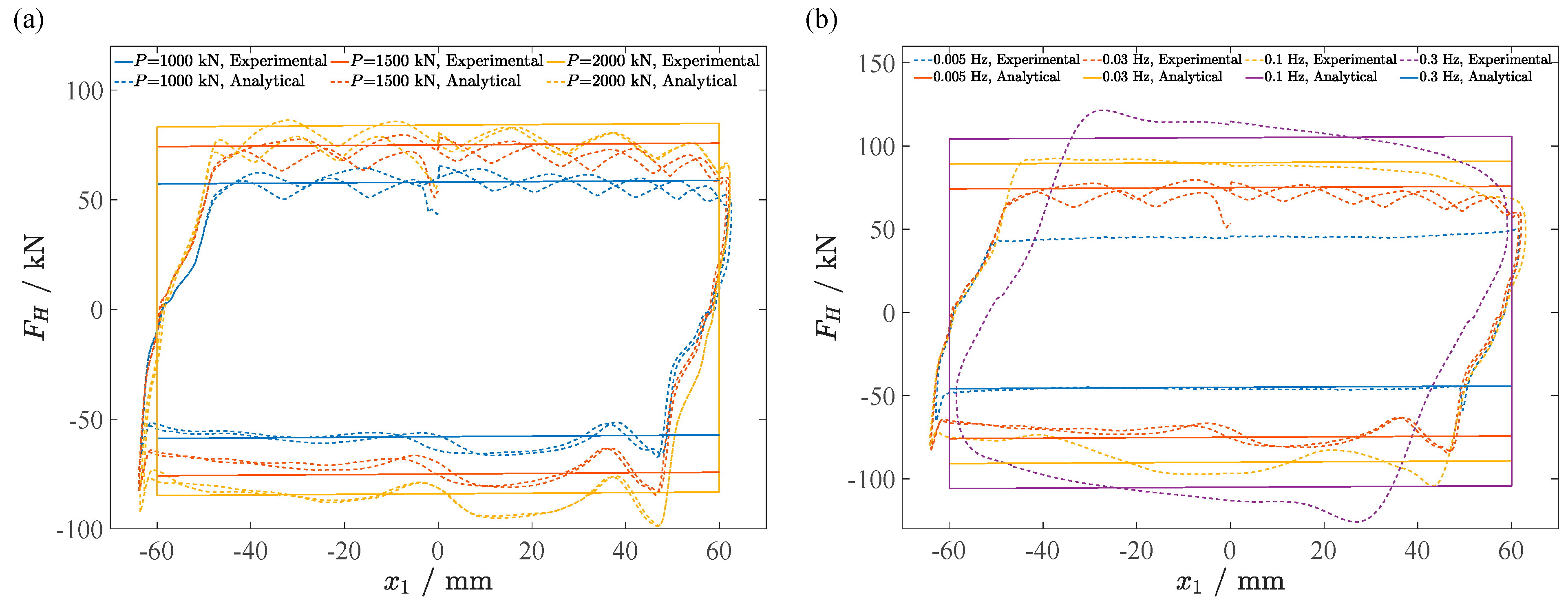
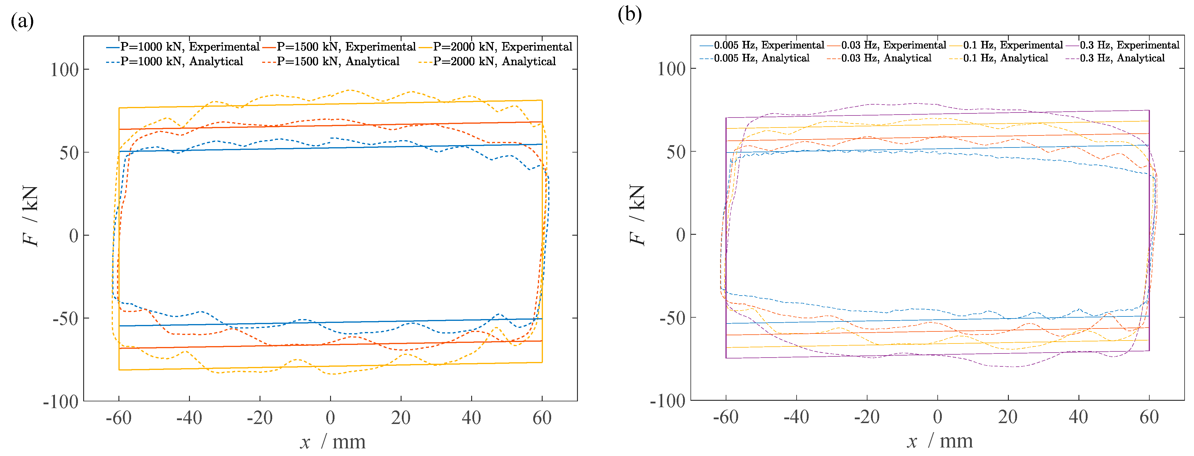
3.1. Analytical Hysteretic Model for the Horizontal Direction

The horizontal force on the ARFSB can be written as
F H = F p + F k = k x 1 + sgn ( x ˙ 1 ) μ H ( x ˙ 1 , P ) P
in which P is the vertical load, x1 is the relative displacement of the top and bottom of the ARFSB, x ˙ 1 is the corresponding relative velocity, sgn(·) is the sign function, F k = k x 1 is the resilience force of the spring, k is the equivalent stiffness of the springs, F p = sgn ( x ˙ 1 ) μ H ( x ˙ 1 , P ) P is the friction force, and μ H ( x ˙ 1 , P ) is the corresponding dynamic friction coefficient.
The horizontal force of the DCFPB can be approximately computed by
F M = P R x 2 + sgn ( x ˙ 2 ) μ M ( x ˙ 2 , P ) P
in which x2 is the relative displacement of the top and bottom of the DCFPB, x ˙ 2 is the corresponding relative velocity, R is the sliding surface’s radius, and μ M ( x ˙ 2 , P ) is the dynamic friction coefficient.
According to the continuity condition, the displacements and velocities satisfy
x = x 1 + x 2
x ˙ = x ˙ 1 + x ˙ 2
in which x and x ˙ are the horizontal displacement and velocity of the proposed isolation bearing.
Equation (4) yields
sgn ( x ˙ ) = sgn ( x ˙ 1 ) = sgn ( x ˙ 2 )
On the other hand, the equilibrium condition yields
F = F H = F M
where F is the horizontal force on the proposed isolation bearing, and inertial forces are ignored.
Substituting Equations (1) and (2) into Equation (6) yields
sgn ( x ˙ 1 ) μ H ( x ˙ 1 , P ) P R + k R x 1 = P x 2 + sgn ( x ˙ 2 ) μ M ( x ˙ 2 , P ) P R
By substituting Equations (5) and (3) into Equation (7), the following is obtained:
sgn ( x ˙ ) μ H ( x ˙ , P ) P R + k R x 1 = P ( x x 1 ) + sgn ( x ˙ ) μ M ( x ˙ , P ) P R
Finally, the analytical hysteretic model in the horizontal direction is obtained by substituting Equations (1) and (6) into Equation (8)
F = P k x + sgn ( x ˙ ) μ H ( x ˙ , P ) P + μ M ( x ˙ , P ) k R P k R + P
Evidently, the proposed isolation bearing is rate-dependent, because both μ H ( x ˙ 1 , P ) and μ M ( x ˙ 2 , P ) are dependent on the rate of the applied force.
To further determine the values of μ H and μ M , x ˙ 1 and x ˙ 2 should be calculated in advance. Taking a derivative to Equation (7) yields
k R x ˙ 1 = P x ˙ 2
in which the absolute values of x ˙ 1 and x ˙ 2 are assumed to be two constants.
Substituting Equation (4) into Equation (10) yields
x ˙ 1 = P P + k R x ˙
x ˙ 2 = k R P + k R x ˙

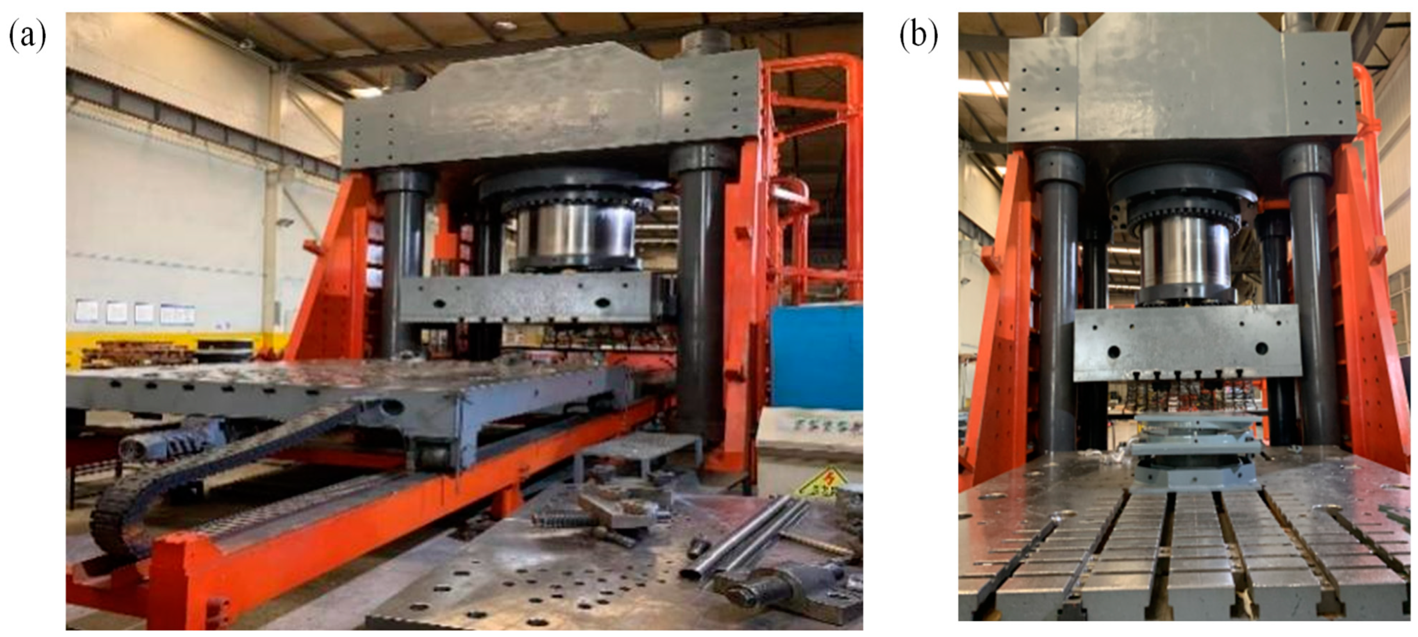
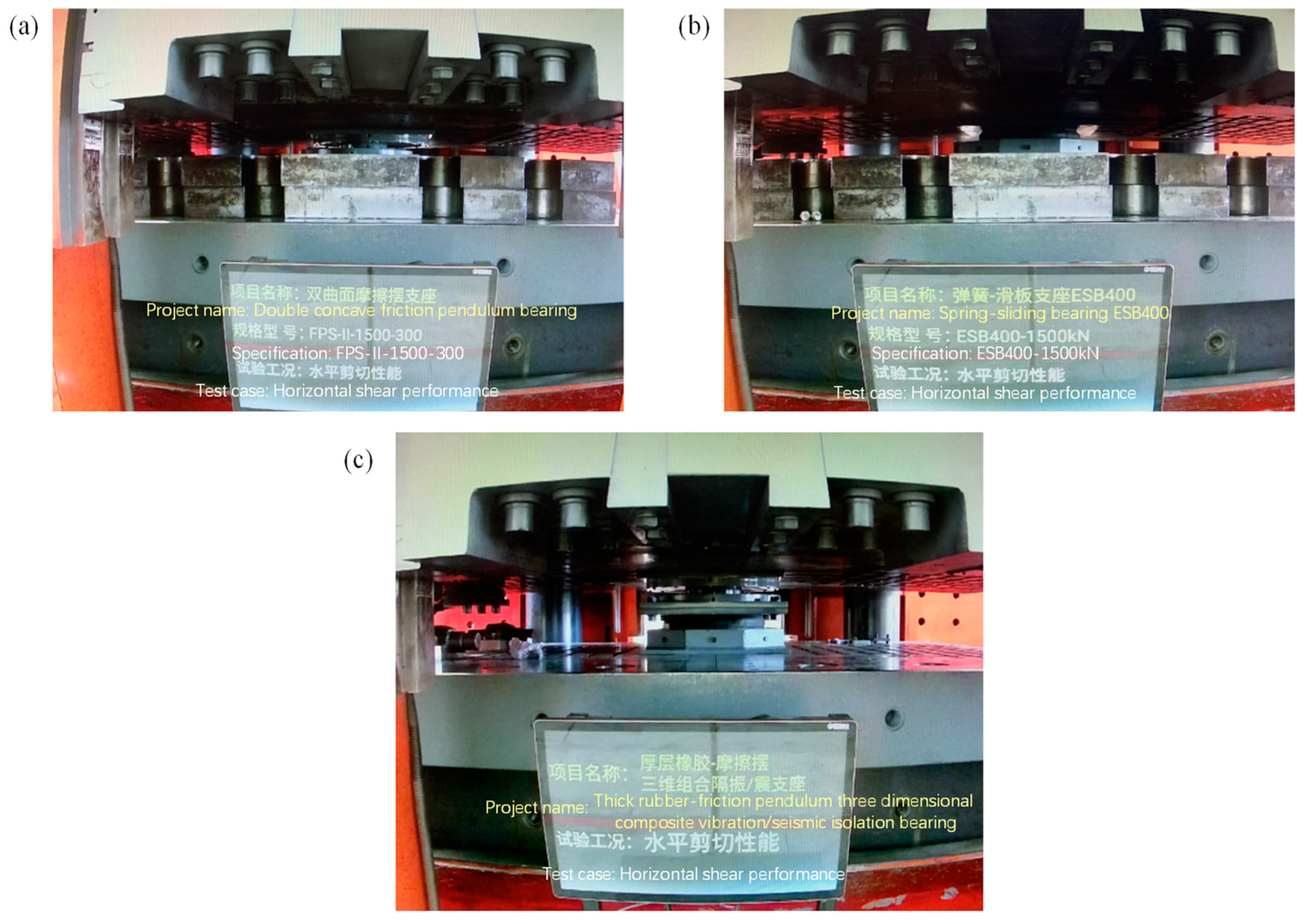
3.2. Experimental Validation of the Proposed Hysteretic Model

In this section, in order to verify the correctness of the proposed hysteretic model, a horizontal shear test was carried out on the proposed isolation bearing. The test was completed in the laboratory of the Zhen’an Science and Technology Production Base in Kunming, China; the test machine used was a 35,000 kN large-scale compression-shear test machine (as shown in Figure 2a), and a full-scale model of the proposed isolation bearing was tested (as shown in Figure 2b).
To validate the analytical hysteretic model proposed in Section 3.1, the dynamic friction coefficient of the ARFSB and the dynamic friction coefficient of the DCFPB were obtained in advance, which was performed through the hysteretic tests in the vertical direction and the corresponding curve fittings (shown in Figure 3a). The hysteretic performances of the ARFSB under different vertical loads (P = 1000, 1500, and 2000 kN) and fixed vertical loads (P = 1500 kN) were tested, respectively. The total spring stiffness of ARFSB is 40 kN/m, and the maximum horizontal displacement is 60 mm. Then, the values μ H ( x ˙ 1 , P ) were obtained by fitting the tested hysteresis curves.
Figure 4 shows the comparison between the hysteresis curve of the ARFSB obtained from the test and the corresponding analytical values obtained by Equation (1), where the dotted line represents the test values and the solid line represents the corresponding analytical values. Table 1 shows the values of μ H ( x ˙ 1 , P ) obtained by the fitting. In the test of the ARFSB (shown in Figure 3b), a quasi-static loading test and a fixed frequency (0.003 Hz) hysteretic performance test were performed. The vertical loads P under quasi-static loading were set to 1000 and 1500 kN, respectively, and the vertical loads P under a fixed frequency (0.03 Hz) were set to 1000, 1500, and 2000 kN, respectively. It was noted that the oscillation on the experimental curves is produced by the loading machine’s limited control over the velocities. In other words, the loading machine cannot preserve a prescribed velocity with sufficient precision in the loading process. In addition, in the analytical model, the time for changing the loading direction is neglected, resulting in two vertical lines at the left and right boundaries of the predicted hysteretic curves. However, in the experiment, it took time for the loading machine to change the loading direction, and the corresponding velocity would first decrease and then increase, resulting in discrepancies between the analytical hysteretic curves and the experimental ones. But in general, the analytical curves match the experimental values.
Figure 5 shows the comparison of the tested hysteretic curves and the corresponding analytical value obtained from Equation (2), where the dotted lines and the solid lines represent the test values and the analytical values, respectively. The values of μ M ( x ˙ 2 , P ) obtained by the fitting are shown in Table 2. The load system used in Figure 5 was intended to obtain the friction coefficient for quasi-static cases, in which the velocity changes from exactly zero to a very small value, causing the overshoots on the experimental curves. Nevertheless, the hysteretic curves predicted by the model are in line with the experimental results, validating the proposed analytical hysteretic model.
To calculate the hysteresis curve described by Equation (9), it was necessary to obtain x ˙ 1 and x ˙ 2 through Equations (11) and (12) in advance. Table 3 shows the results for x ˙ 1 and x ˙ 2 under different frequencies and vertical loads. Afterwards, the corresponding values of μ H ( x ˙ 1 , P ) and μ M ( x ˙ 2 , P ) were obtained through interpolations. Table 4 shows the corresponding results for μ H ( x ˙ 1 , P ) and μ M ( x ˙ 2 , P ) . The predicted hysteretic curves were obtained by taking the corresponding values of μ H ( x ˙ 1 , P ) and μ M ( x ˙ 2 , P ) into Equation (9). Afterward, the predicted hysteretic curves were compared with the corresponding experimental results. Figure 6 shows the comparison between the tested hysteresis curve and corresponding analytical predictions, Figure 6a shows the hysteresis curves under different vertical loads and a fixed loading frequency of 0.1 Hz, and Figure 6b shows the hysteresis curves under different loading frequencies and a fixed load of P = 1500 kN. From Figure 6, it is seen that the hysteresis curves obtained from Equation (9) are in agreement with the corresponding experimental results, validating the correctness of the analytical hysteretic model. In addition, it can be seen from Figure 6 that the energy dissipation capacity of the proposed isolation bearing monotonically increases as the vertical load or the frequency increases, which indicates the proposed isolation would exhibit better performances for cases of large vertical loads or vibrations of higher frequencies.

3.3. Fatigue Performance under Horizontal Loads

To further test the fatigue stability under horizontal loads, the proposed isolation bearing was subjected to multi-cycle reciprocating loadings in the horizontal direction. In the test, the vertical load was set to 1500 kN, the loading frequency was fixed at 0.03 Hz, the maximum displacement was 60 mm, and the total number of cycles was set to 21. Figure 7 shows the corresponding test results. It can be seen from Figure 7 that the area change of the hysteretic loop is small, which proves that the horizontal shear resistance and the hysteretic energy dissipation capacity of the proposed isolation bearing are stable and reliable under cyclic loadings, indicating that the proposed isolation bearing has good fatigue stability. The reasons for the good fatigue stability are concluded as follows: (1) Under the action of horizontal force, the proposed isolation bearing dissipates energy through friction, and all components of the bearing are in an elastic state and no damage has occurred; and (2) The ARFSB and DCFPB have good self-resetting ability, which is conducive to the fatigue stability.

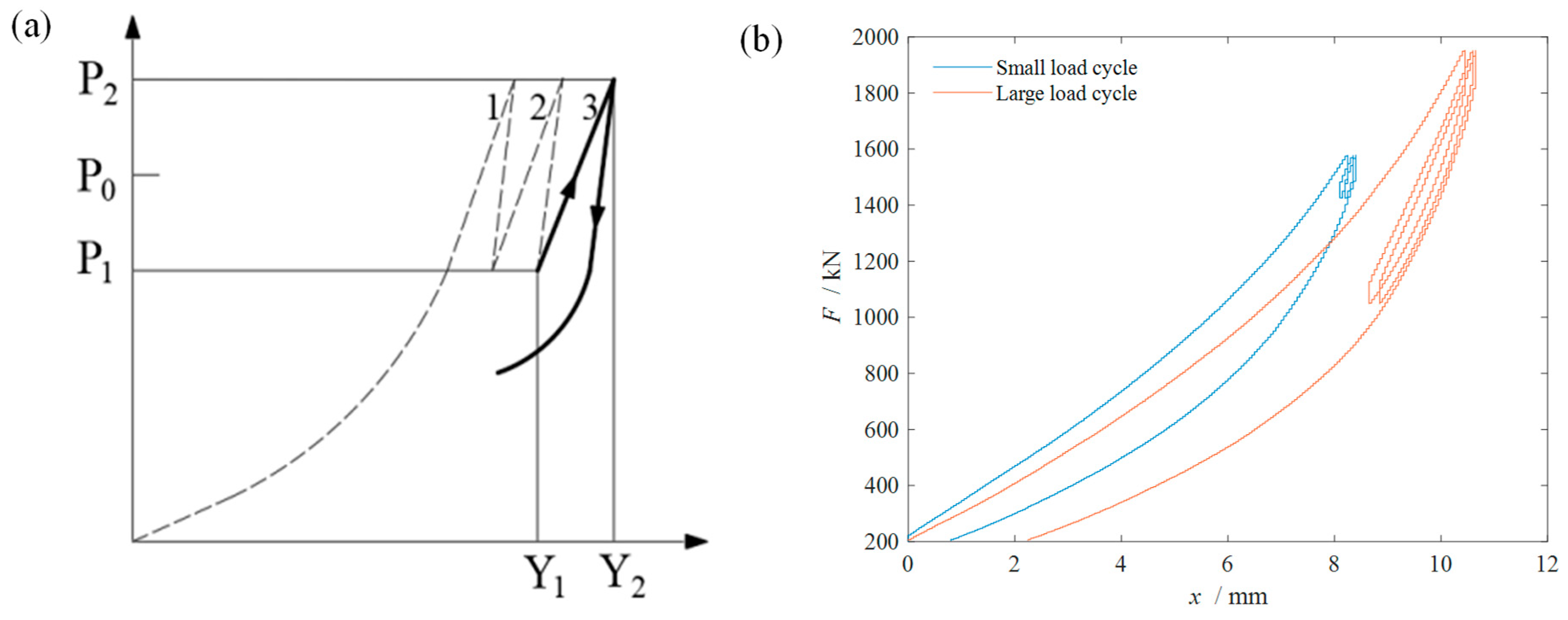
3.4. Vertical Compression Properties

Vertical compression performance is one of the most important characteristics of isolation bearings. Thus, the vertical compression test of the proposed isolation bearing was also performed (shown in Figure 8), for which two test conditions were adopted: the small load cycle (1 ± 5%) and the large load cycle (1 ± 30%). For the small load cycle, the mean load P0, the minimum load P1, and the maximum load P2 were set to 1500, 1425, and 1575 kN, respectively, while for the large load cycle, P0, P1, and P2 were set to 1500, 1050, and 1950, respectively. The loading system and load-displacement curve of the vertical compression test are shown in Figure 9a and Figure 9b, respectively. Table 5 shows the tested vertical stiffnesses: the vertical monotonic stiffness measured under the large load cycle is denoted as Kvm, which represents the working performance of the bearing under moderate earthquakes, and the vertical cyclic stiffness of the bearing measured under the small load cycle is denoted as Kvc, which indicates the working performance of the bearing under frequent vibrations. Considering the relationship between the vertical stiffness test values under different axial loads, it was found that, with the increase of the axial load, the vertical stiffness of the bearing increases significantly, and when the load doubles, the vertical stiffness increases by about 250%. Thus, the proposed bearing is sensitive to axial loads. Such sensitivity is beneficial because the vertical stiffness increases as the vertical load increases, providing additional bearing.

4. Attenuation Effects of Traffic-Induced Vibrations

In this section, the proposed bearing’s attenuation effect on traffic-induced vibrations is analyzed through a field test; Section 4.1 introduces the test scheme and Section 4.2 presents and analyzes the corresponding results. It was noted that, because the attenuation effect of vertical vibrations is only provided by the TRB, the TRB rather than the entire bearing was tested.

4.1. Setup of the Field Test

The field test was carried out in the courtyard of a mechanical equipment company in Guandu District, Kunming City, Yunnan Province. As shown in Figure 10a, the measuring point is adjacent to the Shanghai-Kunming Line (railway) and the Kunming Metro Line 6 (light rail), which is also close to the East Bus Station, the Dabanqiao Station, and the S92 Airport Expressway. Because the traffic-induced vibrations are mainly vertical vibrations and the corresponding attenuation effect is achieved by the LBR only, this field test only studied the vibration attenuation performances of the LBR. It was noted that the influence of vibrations on human comfort is mainly determined by the accelerations, while the displacements and velocities are not as influential for analyses of human comfort. The proposed isolation bearing aims at increasing human comfort through isolating traffic-induced vibrations; consequently, only accelerations are recorded. In the test, two accelerometers were used to collect data: Accelerometer 1 measured the vibrations before isolation and Accelerometer 2 measured the vibrations after isolation. The corresponding test setup and measuring points are shown in Figure 10b and Figure 10c, respectively. To simulate the pressure from the superstructure, three solid bearings with a total weight of eight tons were set on top of the LBR (Figure 10b,c). Altogether, four conditions were tested (shown in Table 6).

4.2. Analysis of the Attenuation Effects

Figure 11 and Figure 12 are the time-domain and frequency-domain analyses of the vibration test, respectively. It can be seen from Figure 11 and Figure 12 that the TRB has a good attenuation effect for traffic-induced vibrations. Table 7 shows the statistics of the corresponding vibration attenuation rates, from which it is seen that the attenuation rates of the TRB are about 50–70%, indicating the proposed isolation bearing’s satisfactory attenuation effect against traffic-induced vibrations. Additionally, it is seen from Figure 12 that most of the vibration frequencies caused by trains and light rail transits are concentrated between 45 and 55 Hz, and the corresponding vibration attenuation effect is significant in this frequency range. However, the frequencies of vibrations caused by automobiles are concentrated between 8 and 23 Hz, and the corresponding vibration attenuation effect is not as outstanding as that of trains and light rail transits but is still acceptable. This is because the TRB has a continuous bandgap ranging from 40 to 55 Hz that completely covers the main frequency range of trains and light rail transits, while its bandgap for lower frequencies is only 12–18 Hz, which fails to cover the main frequency range of automobiles. On the other hand, the degree of Z-direction vibration is another important index for noise measurement. Table 8 shows the statistics of the corresponding degree of Z-direction vibration, from which it can be seen that the degree of Z-direction vibration decreased by about 80%.

5. Conclusions

This paper proposes a new type of 3D isolation bearing for the mitigation of both earthquakes and traffic-induced vibrations, which consists of a TRB, an ARFSB, and a DCFPB. Its working goal is to decompose 3D vibrations into horizontal and vertical vibrations, in which the horizontal vibrations are isolated through the combination of the DCFPB and the ARFSB, and the vertical vibrations are mitigated through the TRB. In addition, this paper derives and experimentally validates the analytical hysteretic model of the proposed isolation bearing and further tests the corresponding fatigue performance and vertical compression performance. Furthermore, the field test demonstrates the bearing’s satisfactory mitigation effect for traffic-induced vibrations. The aim of this research is to propose the isolation bearing as a viable option and to provide its corresponding mechanical properties and vibration mitigation effects against traffic-induced vibration; more research on the proposed isolation bearing will be performed in the future to further study the bearing’s frequency-related properties and seismic performances and to evaluate its effectiveness and energy components, etc. In addition, the following conclusions are drawn:
(1)
The analytical hysteresis model proposed in this paper can accurately describe the horizontal hysteresis behaviors of the proposed isolation bearing;
(2)
A multi-cycle reciprocating loading test proves that the bearing proposed in this paper has satisfactory fatigue performance;
(3)
The vertical compression performance test shows that the proposed isolation bearing has a large axial compression sensitivity; and
(4)
The proposed isolation bearing can efficiently mitigate traffic-induced vibrations.

Author Contributions

Conceptualization, H.X. and Q.W.; methodology, Z.X.; software, Z.X.; validation, Z.X., X.C. and H.X.; formal analysis, Z.X.; investigation, Z.X.; resources, Q.W.; data curation, H.X.; writing—original draft preparation, Z.X.; writing—review and editing, Z.X.; visualization, Z.X.; supervision, Q.W.; project administration, Q.W.; funding acquisition, Q.W and Z.X. All authors have read and agreed to the published version of the manuscript.

Funding

This work was supported by the Open Foundation Project of the Key Laboratory of Earthquake Engineering and Engineering Vibration, Institute of Engineering Mechanics, China Earthquake Administration (No. 2019D01), the National Natural Science Foundation of China (No. 52078395), the Natural Science Foundation of Hubei Province for Distinguished Young Scholars (No. 2023AFA103), the Dawn Program of Knowledge Innovation Project from the Bureau of Science and Technology of Wuhan Municipality (No. 2022010801020357), and the Science Research Foundation of Wuhan Institute of Technology (No. K2021030).

Institutional Review Board Statement

Not applicable.

Informed Consent Statement

Not applicable.

Data Availability Statement

No new data were created or analyzed in this study. Data sharing is not applicable to this article.

Conflicts of Interest

The authors declare no conflict of interest.

Abbreviations

ARFSBauto-reset flat slider bearing
CSSBcurved surface sliding bearing
DCFPBdouble concave friction pendulum bearing
EBelastomeric bearing
FPBfriction pendulum bearing
FREBfiber-reinforced elastomeric bearing
FSSBflat surface sliding bearing
HDRBhigh-damping rubber bearing
LDRBlow-damping rubber bearing
LRBlead-rubber bearing
SBsliding bearing
SREBsteel-reinforced elastomeric bearing
TRBthick rubber bearings
TSBtextured sliding bearing

References

  1. Bertero, V.V. Performance-based seismic engineering: A critical review of proposed guidelines. In Seismic Design Methodologies for the Next Generation of Codes; Routledge: London, UK, 2019; pp. 1–31. [Google Scholar]
  2. Grigorian, M.; Moghadam, A.S.; Sedighi, S. Sustainable seismic design and health monitoring. Struct. Control Health Monit. 2022, 29, e3058. [Google Scholar] [CrossRef]
  3. Forcellini, D. The Role of Redundancy of Infrastructures on the Seismic Resilience (SR) of Sustainable Communities. Sustainability 2023, 15, 11849. [Google Scholar] [CrossRef]
  4. Xia, H.; Cao, Y.; De Guido, R.; Geert, D. Environmental problems of vibrations induced by railway traffic. Front. Archit. Civ. Eng. China 2007, 1, 142–152. [Google Scholar] [CrossRef]
  5. Bariker, P.; Kolathayar, S. A study on trenching techniques for vibration isolation: An overview. In Seismic Hazards and Risk: Select Proceedings of 7th ICRAGEE 2020; Springer: Singapore, 2021; pp. 283–293. [Google Scholar]
  6. Belbachir, A.; Benanane, A.; Ouazir, A.; Harrat, Z.R.; Hadzima-Nyarko, M.; Radu, D.; Işık, E.; Louhibi, Z.S.; Amziane, S. Enhancing the Seismic Response of Residential RC Buildings with an Innovative Base Isolation Technique. Sustainability 2023, 15, 11624. [Google Scholar] [CrossRef]
  7. De Luca, A.; Guidi, L.G. State of art in the worldwide evolution of base isolation design. Soil Dyn. Earthq. Eng. 2019, 125, 105722. [Google Scholar] [CrossRef]
  8. Chen, B.; Dai, J.; Song, T.; Guan, Q. Research and development of high-performance high-damping rubber Materials for high-damping rubber isolation bearings: A review. Polymers 2022, 14, 2427. [Google Scholar] [CrossRef]
  9. Avinash, A.; Krishnamoorthy, A.; Kamath, K.; Chaithra, M. Sliding Isolation Systems: Historical Review, Modeling Techniques, and the Contemporary Trends. Buildings 2022, 12, 1997. [Google Scholar] [CrossRef]
  10. Vaiana, N.; Sessa, S.; Paradiso, M.; Rosati, L. Accurate and efficient modeling of the hysteretic behavior of sliding bearings. In Proceedings of the 7th ECCOMAS Thematic Conference on Computational Methods in Structural Dynamics and Earthquake Engineering, Crete, Greece, 24–26 June 2019. [Google Scholar]
  11. Calvi, P.M.; Calvi, G.M. Historical development of friction-based seismic isolation systems. Soil Dyn. Earthq. Eng. 2018, 106, 14–30. [Google Scholar] [CrossRef]
  12. Fenz, D.M.; Constantinou, M.C. Behaviour of the double concave friction pendulum bearing. Earthq. Eng. Struct. Dyn. 2006, 35, 1403–1424. [Google Scholar] [CrossRef]
  13. Kim, Y.-S.; Yun, C.-B. Seismic response characteristics of bridges using double concave friction pendulum bearings with tri-linear behavior. Eng. Struct. 2007, 29, 3082–3093. [Google Scholar] [CrossRef]
  14. Song, F.; Yang, X.; Dong, W.; Zhu, Y.; Wang, Z.; Wu, M. Research and prospect of textured sliding bearing. Int. J. Adv. Manuf. Technol. 2022, 121, 1–25. [Google Scholar] [CrossRef]
  15. Vaiana, N.; Sessa, S.; Marmo, F.; Rosati, L. An accurate and computationally efficient uniaxial phenomenological model for steel and fiber reinforced elastomeric bearings. Compos. Struct. 2019, 211, 196–212. [Google Scholar] [CrossRef]
  16. Orfeo, A.; Tubaldi, E.; Muhr, A.H.; Losanno, D. Mechanical behaviour of rubber bearings with low shape factor. Eng. Struct. 2022, 266, 114532. [Google Scholar] [CrossRef]
  17. Weisman, J.; Warn, G.P. Stability of elastomeric and lead-rubber seismic isolation bearings. J. Struct. Eng. 2012, 138, 215–223. [Google Scholar] [CrossRef]
  18. De Domenico, D.; Losanno, D.; Vaiana, N. Experimental tests and numerical modeling of full-scale unbonded fiber reinforced elastomeric isolators (UFREIs) under bidirectional excitation. Eng. Struct. 2023, 274, 115118. [Google Scholar] [CrossRef]
  19. Zhou, Y.; Zhang, Z. Experimental and analytical investigations on compressive behavior of thick rubber bearings for mitigating subway-induced vibration. Eng. Struct. 2022, 270, 114879. [Google Scholar] [CrossRef]
  20. Pan, P.; Shen, S.; Shen, Z.; Gong, R. Experimental investigation on the effectiveness of laminated rubber bearings to isolate metro generated vibration. Measurement 2018, 122, 554–562. [Google Scholar] [CrossRef]
  21. Zhang, Z.; Li, X.; Zhang, X.; Fan, J.; Xu, G. Semi-analytical simulation for ground-borne vibration caused by rail traffic on viaducts: Vibration-isolating effects of multi-layered elastic supports. J. Sound Vib. 2022, 516, 116540. [Google Scholar] [CrossRef]
  22. Sheng, T.; Shi, W.x.; Shan, J.z.; Hong, F.y.; Bian, X.c.; Liu, G.b.; Chen, Y. Base isolation of buildings for subway-induced environmental vibration: Field experiments and a semi-analytical prediction model. Struct. Des. Tall Spec. Build. 2020, 29, e1798. [Google Scholar] [CrossRef]
  23. Kikuchi, M.; Aiken, I.D. An analytical hysteresis model for elastomeric seismic isolation bearings. Earthq. Eng. Struct. Dyn. 1997, 26, 215–231. [Google Scholar] [CrossRef]
  24. Murillo, C.; Thorel, L.; Caicedo, B. Ground vibration isolation with geofoam barriers: Centrifuge modeling. Geotext. Geomembr. 2009, 27, 423–434. [Google Scholar] [CrossRef]
  25. Massarsch, K.R. Vibration isolation using gas-filled cushions. In Soil Dynamics Symposium in Honor of Professor Richard D. Woods, Proceedings of the Geo-Frontiers 2005, Austin, TX, USA, 24–26 January 2005; American Society of Civil Engineers: Reston, VA, USA, 2005; pp. 1–20. [Google Scholar]
  26. Zou, C.; Wang, Y.; Zhang, X.; Tao, Z. Vibration isolation of over-track buildings in a metro depot by using trackside wave barriers. J. Build. Eng. 2020, 30, 101270. [Google Scholar] [CrossRef]
  27. Makris, N. Seismic isolation: Early history. Earthq. Eng. Struct. Dyn. 2019, 48, 269–283. [Google Scholar] [CrossRef]
Figure 1. Presentation of the proposed isolation bearing: (a) schematic of planar view, (b) schematic of stereo view, and (c) photo of the real bearing.
Sustainability 15 16374 g001
Figure 2. Presentation of the loading test: (a) the loading machine and (b) the proposed bearing on the loading machine.
Sustainability 15 16374 g002
Figure 3. The hysteretic tests of the bearings: (a) the DCFPB, (b) the ARFSB, and (c) the proposed isolation bearing.
Sustainability 15 16374 g003
Figure 4. Horizontal hysteresis performance of the ARFSB: (a) frequency = 0.03 Hz and (b) P = 1500 kN.
Sustainability 15 16374 g004
Figure 5. Hysteresis performance of the DCFPB: (a) quasi-static and (b) frequency = 0.03 Hz.
Sustainability 15 16374 g005
Figure 6. Validation of the analytical hysteresis model: (a) fixed frequency = 0.03 Hz and (b) fixed load = 1500 kN.
Sustainability 15 16374 g006
Figure 7. Fatigue test of the proposed isolation bearing.
Sustainability 15 16374 g007
Figure 8. Vertical compression test of the proposed isolation bearing.
Sustainability 15 16374 g008
Figure 9. Vertical compression test of the proposed bearing: (a) loading system and (b) load-displacement curves.
Sustainability 15 16374 g009
Figure 10. Setup of the field test: (a) the test set and the surroundings, (b) the layout of the field test, and (c) the positions of the accelerometers and the laminated rubber bearing.
Sustainability 15 16374 g010
Figure 11. Time-domain analysis: (a) Condition 1, (b) Condition 2, (c) Condition 3, and (d) Condition 4.
Sustainability 15 16374 g011
Figure 12. Frequency-domain analysis: (a) Condition 1, (b) Condition 2, (c) Condition 3, and (d) Condition 4.
Sustainability 15 16374 g012
Table 1. Fitting results of μ H ( x ˙ 1 , P ) .
0.005 Hz (1.2 mm/s)0.03 Hz
(7.2 mm/s)
0.1 Hz (24.0 mm/s)0.3 Hz (72.0 mm/s)
1000 kN0.040
1500 kN0.0400.0450.0500.055
2000 kN0.055
Table 2. Fitting results of μ M ( x ˙ 2 , P ) .
0 Hz (0.0 mm/s)0.03 Hz (12.0 mm/s)
1000 kN0.0250.035
1500 kN0.0200.030
2000 kN0.025
Table 3. Calculation results of x ˙ 1 and x ˙ 2 under different frequencies and vertical loads (speed unit: mm/s).
0.005 Hz0.03 Hz0.1 Hz0.3 Hz
1000 kN x ˙ 1 = 21.6,
x ˙ 2 = 2.4
1500 kN x ˙ 1 = 1.12, x ˙ 2 = 0.08 x ˙ 1 = 6.72,
x ˙ 2 = 0.48
x ˙ 1 = 22.4,
x ˙ 2 = 1.6
x ˙ 1 = 67.0,
x ˙ 2 = 5.0
2000 kN x ˙ 1 = 22.8,
x ˙ 2 = 1.2
Table 4. Interpolation results of μ H ( x ˙ 1 , P ) and μ M ( x ˙ 2 , P ) under different frequencies and vertical loads.
0.005 Hz0.03 Hz0.1 Hz0.3 Hz
1000 kN μ H = 0.049,
μ M = 0.026
1500 kN μ H = 0.038,
μ M = 0.020
μ H = 0.044,
μ M = 0.021
μ H = 0.050,
μ M = 0.022
μ H = 0.56,
μ M = 0.0023
2000 kN μ H = 0.050,
μ M = 0.018
Table 5. Test results of the proposed isolation bearing’s vertical stiffnesses.
Working ConditionInitial
Stiffness
P = 1000 kNP = 1500 kNP = 2000 kN
Large load cycle Kvm/(kN·mm−1)248.13311.87508.47772.25
Small load cycle Kvc/(kN·mm−1)248.13392.71532.53782.60
Table 6. Test conditions.
ConditionVibration Source
Condition 1Railway trains
Condition 2Automobiles
Condition 3Coming light rail transits
Condition 4Leaving light rail transits
Table 7. Effective accelerations and attenuation rates.
ConditionVibration SourceBefore Isolation (m/s2)After isolation (m/s2)Attenuation Rate
Condition 1Railway trains0.0290.01352.9%
Condition 2Automobiles0.0120.00558.7%
Condition 3Coming metro trains0.0210.00669.0%
Condition 4Leaving metro trains0.0130.00467.4%
Table 8. Degree of Z-direction vibration.
ConditionVibration SourceBefore Isolation (dB)After Isolation (dB)Decrease Rate
Condition 1Railway trains78.7259.5580.83%
Condition 2Automobiles53.5632.6779.11%
Condition 3Coming metro trains73.8057.1783.37%
Condition 4Leaving metro trains70.4250.3579.74%
Disclaimer/Publisher’s Note: The statements, opinions and data contained in all publications are solely those of the individual author(s) and contributor(s) and not of MDPI and/or the editor(s). MDPI and/or the editor(s) disclaim responsibility for any injury to people or property resulting from any ideas, methods, instructions or products referred to in the content.

