Abstract
The diagrid core-tube structure has been widely used in high-rise buildings in recent years, but there are few studies on the sustainable energy dissipation measures and seismic performance improvement of such structural systems. Because the coupling beam is the element connecting the inner tube and the outer tube in the diagrid structure, it is the first seismic defense line and an important energy-dissipation member in the seismic design of the overall structure. Therefore, this paper replaces the traditional reinforced concrete coupling beam of the inner tube of the shear wall with a replaceable energy-dissipation steel coupling beam, and the strength, stiffness, and stability of the replaceable steel coupling beam are designed to improve the sustainability of the structure. By changing the position of the replaceable coupling beam, the relative stiffness of the inner and outer tubes of the diagrid tube structure, and the plane form of the structure, the static elastoplastic analysis and seismic response energy analysis of different diagrid tube structures are carried out, and the influence of the replaceable coupling beam on the sustainable seismic performance of the diagrid tube structure is studied. The results show that the replaceable coupling beams have little effect on the ultimate bearing capacity of the structure, but the ductility and sustainability of the structure are significantly improved, and the whole building layout is the optimal layout scheme. The setting of replaceable coupling beams makes the diagrid tube structure show hysteretic energy-dissipation earlier under the action of large earthquakes, and the proportion of hysteretic energy-dissipation is greatly improved, which reduces the inter-story drift ratios and the damage degree of the diagrid columns under the action of large earthquakes. When the relative stiffness of the outer tube of the diagrid tube structure is small or the plane form of the structure is a regular quadrilateral, the application of replaceable coupling beams is more effective in improving the ductility and sustainability of the structure and reducing the damage to the diagrid column under large earthquakes.
1. Introduction
The diagrid core-tube structure is a kind of double lateral force-resistance system composed of an external diagrid and an inner core tube. The diagrid is composed of a huge cross-diagrid column and floor ring beam, which is like a grid. Its diagrid column mainly resists vertical self-weight and horizontal load in the form of axial force. It is a very efficient lateral force-resistance system, and the external contour of the structure is novel and beautiful. It is mostly used as an important landmark high-rise and super-high-rise building structure. However, there are still few studies on the sustainable energy-dissipation measures and seismic performance improvement of such structural systems [1,2,3].
At present, the research on diagrid tubes mainly focuses on the theoretical calculation of the lateral stiffness [4,5], plastic development research, diagrid angle and plane form optimization, diagrid node research, and so on [6,7,8]. Moon [9] investigated the optimal configurations of today’s prevalent structural systems for tall buildings to generate higher lateral stiffness and maximize their structural efficiency. Shi and Zhang [10] proposed a simplified calculation method that considers the shear lag effect of diagonal tube structures, so that the optimal angle of diagonal columns can be determined under the basic condition of only knowing the aspect ratio of the structure, and the shear lag effect of diagonal structures can be quickly estimated using the proposed simplified method. Leonard [11] studied the shear lag effect of diagrid structures and analyzed the influence of parameters such as the angle and spacing of the diagrid columns on the shear lag effect of structures. Roshani [12] analyzed the robustness of high-rise diagrid structures with various perimeter configurations at a seismic hazard level. The results showed that diagrid structures have relatively high robustness and that using perimeter triangular elements can reduce the degradation of structures after the earthquake. The main vibration mode is translation, while torsion effect is not obvious. Li et al. [13] proposed a diagrid structure with shear energy-dissipation segments and plastic hinges at specific beam ends. The plastic development, energy-dissipation capacity, and seismic performance of this structure under different degrees of earthquakes were studied by nonlinear dynamic time history analysis, and the feasibility of the seismic performance objectives of the structure was discussed. The research on the seismic performance of the diagrid tube structure is mostly focused on the response characteristics and influencing factors of the structure under earthquake action, and there are few methods and measures to improve its sustainable seismic performance. However, the existing research findings, such as the poor ductility, weak energy-dissipation, and the first failure of coupling beams under earthquake action of diagrid tube structures, make relevant scholars need to explore more methods to improve the sustainable seismic performance and the repairability and sustainability of coupling beams after failure under earthquake action. At present, the research on replaceable coupling beams mainly focuses on steel coupling beams and is mainly applied to frame structures. Farsi et al. [14] tested replaceable steel coupling beams with end-plate connections to evaluate the seismic behavior and replaceability after the damage of coupling beams with different strengths and stiffness. The results showed that the failure of the coupling beam is characterized by concentrated inelastic deformation and energy dissipation on the web, and the failure of the shear wall is very small. The strength, stiffness, and connection mode of the coupling beam have a great influence on the ductility and energy-dissipation capacity. Shahrooz et al. [15] proposed a design method for steel coupling beams with replaceable “fuses”. When the structure undergoes a design-level earthquake, the “fuse” is the main energy-dissipation component, while the main part of the coupling beam and other components remain elastic. Through the quasi-static test, Ji et al. [16] studied the influence of the connection mode of the section and non-energy-dissipation beam on the seismic performance of replaceable coupling-able coupling beam, and they analyzed the post-earthquake replaceability of the replaceable coupling beam through the residual deformation under different connection modes. In general, there are more experimental and simulation studies at the component level, and less research on the overall structure with replaceable coupling beams, and most of them are aimed at a simple piece of bottom-coupled shear wall or some substructures [17,18,19,20,21].
Although the diagrid tube structure is widely used, how to improve its energy-dissipation capacity still needs further research. Based on the existing research status of the diagrid tube and the research on the replaceable coupling beam, this paper proposes to apply the replaceable coupling beam to the inner tube of the shear wall to improve the sustainability of the structure. Considering the layout position of the replaceable coupling beam and the related structural parameters, the influence of the replaceable coupling beam on the sustainable seismic performance of the diagrid grid tube structure is discussed by static elastoplastic analysis and seismic response energy analysis.
2. Replaceable Coupling Beam Design Principle in Diagrid Core-Tube Structure
The coupling beam is the beam connecting the wall limbs in a shear wall structure. As the first seismic defense line and an important energy dissipation component of a shear wall structure, whether the design is reasonable has an important influence on the seismic performance and engineering economy of the building structure. Under the action of lateral load, the structure produces lateral deformation. The rotation angles at both ends of the coupling beam are the same, and the inflection point is located in the middle of the span. The bending moment of the coupling beam is the largest at both ends and zero in the middle, and the shear force is equal along the length direction of the beam. The coupling beam generally shows shear deformation. The deformation and force diagrams of the coupling beam are as follows (Figure 1):
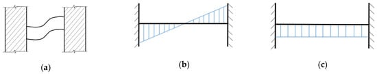
Figure 1.
Deformation and force diagrams of a coupling beam: (a) deformation diagram; (b) bending moment diagram; and (c) shear diagram.
The coupling beam generally has the characteristics of a small span, large section, and large stiffness of the wall connected to the coupling beam. Under the action of the earthquake, the coupling beam will enter the plastic yield stage before the wall limb, the stiffness will degenerate, and the deformation will increase rapidly, thus consuming a lot of seismic energy. At the same time, the plastic hinge still maintains the constraint effect on the shear wall, which can transfer a certain bending moment and shear force. The energy dissipation of coupling beams during earthquakes plays an important role in reducing the internal force and delaying the yielding of coupling beams. Therefore, coupling beams are allowed to crack or damage under the action of a design earthquake, which can protect the shear wall, improve the ductility of the whole structure and realize multi-channel seismic defense. According to the above characteristics of the coupling beam, the coupling beam is designed as a replaceable member. The replaceable coupling beam is composed of an energy-dissipative beam section, a non-energy-dissipative beam section, and a connection, as shown in the Figure 2.

Figure 2.
Replaceable coupling beam diagram.
Reinforced concrete coupling beams are generally designed according to the principle of “strong shear and weak bending”, that is, the failure of coupling beams under load begins with the bending yield. This is because the shear failure is a brittle failure, the deformation of the coupling beam is very small, the energy consumption is very weak, and as the lateral stiffness of the whole structure suddenly decreases, the deformation increases, resulting in a cumulative P–∆ effect, which is very unfavorable to the structure. The bending failure is a ductile failure. The development of a plastic hinge at the beam end can absorb a large amount of seismic energy. At the same time, the plastic hinge can transfer a certain bending moment and shear force, maintain the overall stiffness of the shear wall structure, and have a positive effect on weakening the internal force and deformation of the wall.
However, experimental studies have shown that when the span-to-height ratio of the coupling beam is small, the coupling beam often undergoes shear failure. Even if the design meets the “strong shear weak bending”, the beam end of the coupling beam first yields and forms a plastic hinge. However, because the beam end is connected to the wall limb, the damage to the beam end will also cause damage to the wall limb, which will bring great economic costs to post-earthquake repair.
In this paper, the research and design of replaceable steel energy-dissipative coupling beams are carried out. For a steel coupling beam, its yield mode is related to the value of the length ratio [22], where is the length of the energy-dissipative beam section, is the plastic bending bearing capacity of the beam section, and is the plastic shear bearing capacity of the beam section. When , the yield of the coupling beam is the web shear yield; when , the yield of coupling beam is the bending yield of the end section; when , the yield of coupling beam is the bending–shear coupled yield. As shown in Figure 3, the test [23] shows that the steel coupling beam with a reasonable design has a larger plastic rotation angle and stronger energy-dissipation capacity under the shear yield mode. Therefore, the replaceable coupling beam is designed as shear yield, and its energy dissipation beam section is located in the middle of the span, which avoids the unfavorable factor that the beam end deforms too much to damage the wall limb when the bending yield occurs, and the energy dissipation capacity is also stronger.
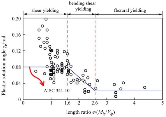
Figure 3.
Relationship between the length ratio and plastic rotation of steel coupling beams [23].
2.1. Types of Energy-Dissipative Beam Sections
The principle of a replaceable coupling beam is that the energy-dissipation beam section has smaller yield strength and better deformation ability than the non-energy-dissipation beam section. Its realization ways include mid-span section or material weakening, friction damper [23], web mid-span opening [24], viscoelastic damper [25], etc. Studies have confirmed that the above types of energy-dissipative beams have a certain energy-dissipative capacity and post-earthquake repairability, but there are still some shortcomings. For example, the opening of the mid-span web is easy to cause stress concentration at the angle of the hole. It is difficult to accurately control the surface pressure and friction coefficient in the friction damper, and there is difficulty in sliding after the friction damper is placed for a long time. The viscosity coefficient and stiffness coefficient of the viscoelastic damper are greatly affected by the temperature and its material is polymer material, and its durability is poor.
The cross-section or material weakening method has more advantages in engineering applications. The I-steel energy-dissipation beam section is easy to manufacture and economical, and the controllability of the design parameters of the I-steel energy-dissipation beam section is better than other dampers. Therefore, the replaceable coupling beam is designed as a shear-yielding coupling beam with a weakened mid-span section. The design goal of the replaceable coupling beam is as follows: the replaceable coupling beam should have the same or similar stiffness and strength to the original coupling beam and keep elastic under small earthquakes; under the action of medium and large earthquakes, the energy-dissipation beam section of the replaceable coupling beam first shears and yields, fully dissipates energy, and the non-energy dissipation beam section remains elastic. After the earthquake, only the energy-dissipation beam section needs to be replaced. It can be seen that the design of replaceable coupling beams should not only meet the requirements of stiffness and strength but also have good deformation capacity to give full play to the role of energy consumption.
2.2. Strength Design
Although the replaceable coupling beam energy-dissipation beam section is relatively weak, its strength must follow the original structure’s internal force design requirements, which need to meet the following formula:
where : shear design value of energy dissipation beam section; and : original coupling beam design shear.
The yield mode of the energy-dissipation beam section is shear yield. When the energy-dissipation beam section is subjected to shear yield, the bending moment is . Therefore, the bending moment design value of the energy-dissipation beam section should be greater than , and there is a certain margin. AISC [22] stipulates the following:
Under the action of the design earthquake, the plastic deformation of the replaceable coupling beam is concentrated in the energy-dissipative beam section, and the non-energy-dissipative beam section should not yield. Its shear and bending bearing capacity should be greater than the ultimate bearing capacity of the corresponding energy-dissipative section, as follows:
where : design shear force of the non-dissipative beam section; : design bending moment of the non-dissipative beam section; : super-strength factors of the shear capacity the of energy-dissipative beam section, 1.5.
2.3. Stiffness Design
The coupling beam transmits the shear force and bending moment, which restrains the shear wall limb. The coupling beam should have enough stiffness to maintain the lateral stiffness of the whole shear wall structure. The design of a replaceable coupling beam should satisfy that its initial stiffness is close to that of the original coupling beam. According to the force characteristics of the coupling beam, take half of the structure, two kinds of coupling beam stiffness analyses and calculation diagrams are shown in Figure 4.
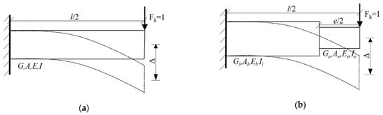
Figure 4.
Diagrams of the coupling beam stiffness calculation: (a) original coupling beam, (b) replaceable coupling beam.
In the figure, is the net span of the original coupling beam; is the cross-sectional area of the original coupling beam; is the inertia moment of the original coupling beam section; and are the elastic modulus and shear modulus of the original coupling beam concrete, respectively; is the length of the replaceable coupling beam energy-dissipation beam section; and are the cross-sectional area and cross-sectional moment of inertia of the energy-dissipation beam section, respectively; and are the elastic modulus and shear modulus of the energy-dissipation beam concrete; and are the cross-sectional area and moment of inertia of the non-dissipative beam section; and are the elastic modulus and shear modulus of the concrete in the non-dissipation beam section, respectively.
According to the displacement formula of a plane bar structure under load, the shear displacement and bending displacement of two kinds of coupling beams under unit vertical shear force can be obtained, and then the stiffness of two kinds of coupling beams can be obtained. The calculation is as follows:
where : original coupling beam’s section shear coefficient; : shear behavior coefficient of the non-dissipative beam section of the replaceable coupling beam; : shear behavior coefficient of the replaceable coupling beam, values of , and are shown in Table 1; : lateral stiffness of the original coupling beam; : lateral stiffness of the replaceable coupling beams; : stiffness coefficient should satisfy , so that the stiffness of the replaceable coupling beam is not less than that of the original coupling beam.

Table 1.
Common section shear shape coefficients.
2.4. Stability Requirements
To prevent the local buckling of the flange and web of the replaceable coupling beam, according to the specification [16], the width-to-thickness ratio of the flange extension and the height-to-thickness ratio of the web should meet the following formula:
where : flange extension width; : flange thickness; : web height; : web thickness; : larger value of the slenderness ratio of the beam in both directions.
3. Calculation Model of Diagrid Core-Tube Structure of High-Rise Buildings with Replaceable Steel Coupling Beams
3.1. Model Introduction
Referring to the reasonable model of the actual project of Guangzhou West Tower [26,27] and some scholars [28,29], a diagrid outer tube shear wall inner tube structure model was designed in Chengdu, Sichuan Province. Figure 5 shows the geometric parameters of the model through the complete model facade and the partially enlarged three-dimensional model. The floor within the range of a cross-diagrid column is defined as a module, 6 layers as a module, and modules 1 to 6 from bottom to top. The total height of the structure is 136 m, and the height of the layer is 4 m, a total of 36 layers. The plane form is a square diagrid outer tube with a side length of 36 m and a square shear wall inner tube with a side length of 18 m. The diagrid outer cylinder is composed of a concrete-filled steel tubular diagrid column (CFST) and an I-shaped steel ring beam. The angle of the diagrid column is about 69 degrees, which is in the best angle range. The diameter of the diagrid column of modules 1 to module 3 is 700 mm, and the diameter of the diagrid column of modules 4 to module 6 is 550 mm. The wall thickness of the steel tube is 20 mm, and the section of the I-shaped steel ring beam is 300 mm × 300 mm × 10 mm ×16 mm. The inner tube is a coupling beam shear wall, the module 1 to module 3 shear wall thickness is 400 mm, the module 4 to module 6 shear wall thickness is 300 mm, and the coupling beam is steel coupling beam. The model materials are Q345 (yield strength is 345 MPa, steel), HRB400 (yield strength is 345 MPa, steel bar), and C60 (the design value of axial compressive strength is 27.5 N/mm2, concrete).
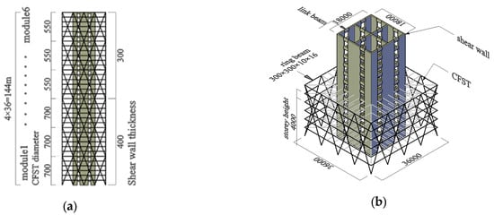
Figure 5.
Diagrid core-tube structure model: (a) elevation view, (b) overall view.
3.2. Material Constitutive Model
- (1)
- Unconfined concrete
The non-constrained components of the shear wall adopt unconfined concrete and its constitutive material adopt the uniaxial compression stress–strain curve of concrete specified in the mixed specification [30], which can be calculated by the following formula:
where : uniaxial compressive stress of concrete; : elastic moduli of concrete; : concrete compressive strain; : parameter is 3.00; : the representative value of the uniaxial compressive strength of concrete, the standard value is 38.5 N/mm2; : uniaxial compressive strength; : the corresponding peak compressive strain of concrete, 0.002; : damage evolution parameters of concrete under uniaxial compression.
The constitutive relation curve of C60 unconfined concrete is shown in Figure 6:
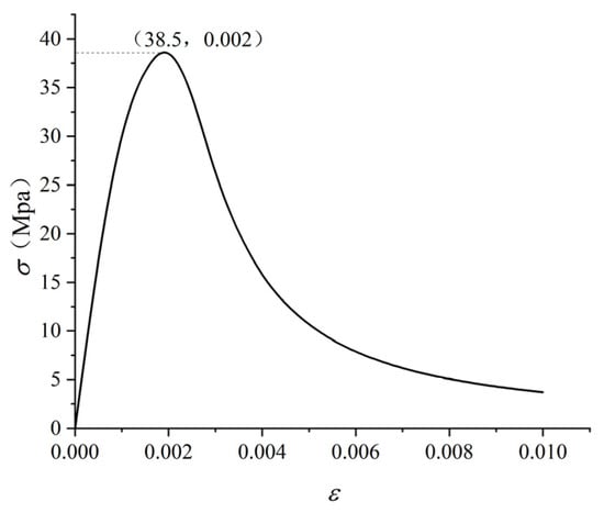
Figure 6.
Constitutive relation curve of C60 unconfined concrete.
- (2)
- Steel tube confined concrete
Steel tube confined concrete adopts the constitutive relation of concrete in a three-dimensional stress state proposed by Zhong [31]:
where : steel tube confined concrete stress; : concrete cube compressive strength; : steel yield point; : standard value of the axial compressive strength of concrete; : sectional areas of steel pipe; : cross-sectional area of concrete. The unit of is MPa and the unit of is 1.0 × 10⁻⁶. The constitutive relation curves of core concrete under two constraint conditions are shown in Figure 7:

Figure 7.
Constitutive relationship of steel tube confined concrete.
- (3)
- Confined concrete
In the model, part of the concrete of the shear wall constraint member is confined concrete. The international constitutive model of confined concrete usually takes the Mander confined concrete constitutive model [32]. Figure 8 is the constitutive curve of Mander-confined concrete.
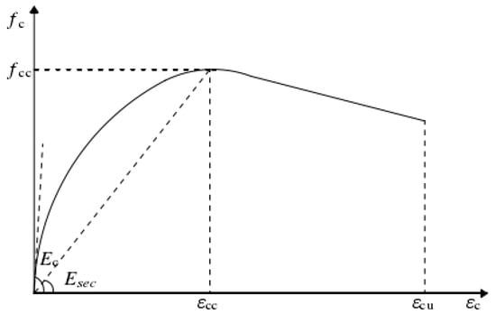
Figure 8.
Constitutive curve of Mander confined concrete.
- (4)
- Steel constitutive
A trilinear constitutive relation is used, as shown in Figure 9:
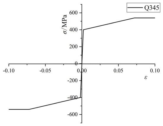
Figure 9.
Trilinear steel constitutive.
In summary, according to the design method in the second section, the cross-section information of the original coupling beam and the replaceable coupling beam in the diagrid core-tube structure model is shown in Table 2.
Table 2.
Coupling beam section parameters.
4. Pushover Analysis of Diagrid Tube Structures with Replaceable Steel Coupling Beams
The original model is numbered XJ0. Based on the XJ0 model, the four comparative analysis models of XJ1, XJ2, XJ3 and XJ4 are established by setting the replaceable coupling beams to study the influence mechanism of setting replaceable coupling beams on the elastic–plastic mechanical performance of the diagrid tube structure and the reasonable arrangement range of replaceable coupling beams. XJ0 is an diagrid tube model without replaceable coupling beams. Based on XJ0, the coupling beams of modules 1, 2, 3, 4, 5, 6, and the whole floor are replaced with replaceable coupling beams, that is, the XJ1, XJ2, XJ3, and XJ4 models. The red part in Figure 10 is expressed as replaceable coupling beams.

Figure 10.
Replaceable coupling beam setting position diagrams: (a) XJ1; (b) XJ2; (c) XJ3; and (d) XJ4.
Pushover simulation calculation is carried out for the above five comparison models. First, the first 15-order vibration modes of the structure are calculated, then the gravity load is applied, and finally, the pushover analysis is carried out according to the distribution mode of the horizontal load along the height of the first-order vibration mode and the displacement control method until the whole structure reaches the limit state, that is, when the pushover load is basically unchanged, the structural deformation increases rapidly and the stable bearing capacity is lost. The base shear-top displacement/overall height curves of the five structural models are shown in Figure 11:
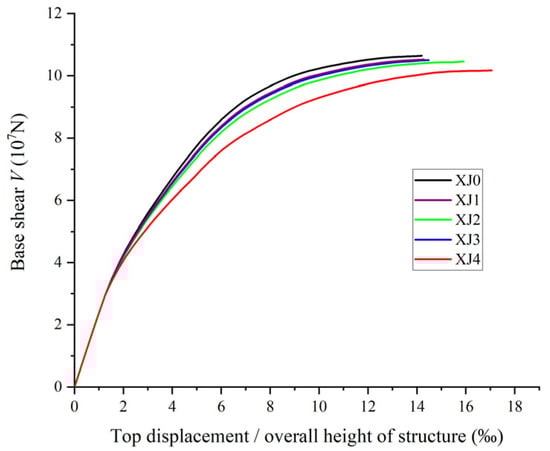
Figure 11.
Pushover curves.
4.1. Stiffness Degradation
The lateral stiffness degradation of the five structural models is shown in Figure 12.
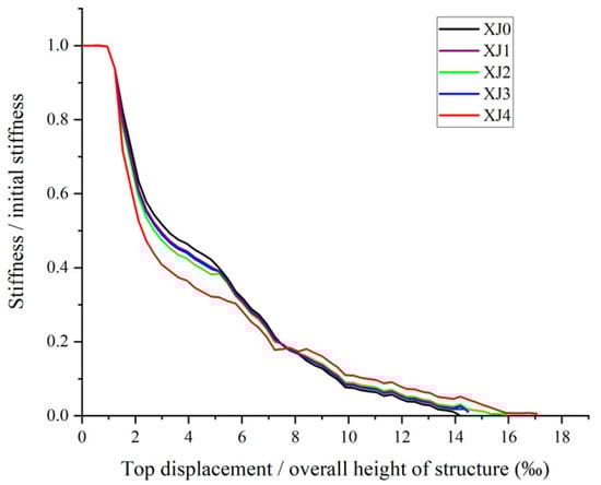
Figure 12.
Stiffness degradation curves.
It can be seen from Figure 12 that with the increase in pushover displacement, the changing trend of lateral stiffness of each model is similar, and the overall trend is fast first and then slow. Compared with the XJ0 structural model, the XJ1, XJ2, XJ3 and XJ4 structural models with replaceable coupling beams have faster lateral stiffness degradation in the early stage and slower lateral stiffness degradation in the later stage. When the top displacement/overall height of the structure is 14.2‰, the lateral stiffness of the XJ0 structural model is almost zero, and when the stable bearing capacity is lost, the XJ1, XJ2, XJ3, and XJ4 structural models still have certain stiffness and can continue to bear. The order of the complete degradation of the lateral stiffness of the five structural models is XJ0, XJ1, XJ3, XJ2, and XJ4. The influence of setting the replaceable coupling beam on the lateral stiffness of the diagrid tube structure is to make the diagrid tube structure complete the lateral stiffness degradation in a larger lateral deformation range. The degree of influence is related to the location range of the replaceable coupling beam.
4.2. Ultimate Bearing Capacity and Ultimate Displacement
The relative influence of setting replaceable coupling beams on the ultimate bearing capacity and ultimate displacement of the diagrid tube structure is shown in Figure 13. The ultimate bearing capacity and ultimate displacement of the XJ3 and XJ1 models are very small compared with the XJ0 model, only between −1.41% and 2.04%. The XJ2 and XJ4 models obtained a larger ultimate displacement increase under the condition of less loss of the ultimate bearing capacity, and the ultimate displacement of XJ4 increased by 20.14% compared with XJ0, which is of positive significance to improve the original poor ductility of the diagrid tube.
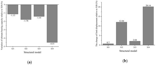
Figure 13.
Comparison of the limit states of the structural model and XJ0: (a) limit bearing capacity change; and (b) limit displacement change.
4.3. Yield Law of Components
As shown in Figure 14, with the increase in lateral displacement, the members of the five models yield successively in the process of pushover. The yield order of the five structural models is coupling beam yield, diagrid column concrete yield, diagrid column steel tube yield, shear wall concrete yield, shear wall steel bar yield, and diagrid column concrete crushing. It can be seen that the setting of replaceable coupling beams will not change the yield sequence of the diagrid tube structure. The phenomenon that the diagrid column concrete and the steel tube yield before the shear wall in the diagrid tube structure reflects the essence that the diagrid column of the web mainly produces axial deformation and axial force under lateral displacement.
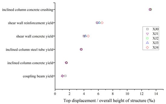
Figure 14.
Yield law of the components.
Although setting replaceable coupling beams does not change the component service order of the diagrid tube structure, it effects the yield time of some components. Compared with the XJ0 structural model, the coupling beams of the XJ1, XJ2, XJ3, and XJ4 structural models yield earlier, while the shear wall concrete and steel yield are delayed. The energy-dissipation principle of the replaceable coupling beam is to make the energy-dissipation beam section enter the plasticity in advance. The energy-dissipation beam section adopts Q235 (yield strength is 345 MPa, steel) with a low yield point, so the four model coupling beams with replaceable coupling beams yield in advance. Because the replaceable coupling beam yields earlier than the traditional coupling beam and the plastic distribution range is wider, the overall lateral stiffness of the shear wall structure decreases, the internal force growth slows down, and the component yield is relatively delayed.
4.4. Outer Tube–Inner Tube Collaborative Force
Figure 15 shows the shear distribution ratio of the inner and outer tubes of the five structural models. It can be seen that the diagrid outer tube is the main lateral force-resisting component in the diagrid tube structure, and the inner tube of the shear wall is the secondary lateral force-resisting component. In the pushover process, the base shear ratio of the diagrid outer tube of the five structural models is not less than 65%. Compared with the XJ0 structural model, the proportion of the base shear force of the diagrid outer tube in the XJ1, XJ2, XJ3 and XJ4 structural models with replaceable coupling beams has increased to varying degrees. However, it does not increase the base shear force of the diagrid outer tube but reduces the base shear force of the shear wall. Setting replaceable coupling beams has a regulatory effect on the synergistic force of the inner and outer tubes of the diagrid tube structure.
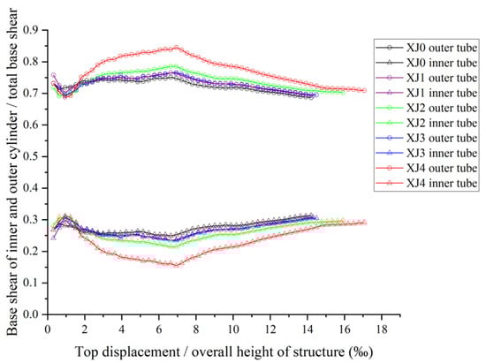
Figure 15.
Base shear ratios.
5. Ductility Analysis of Diagrid Core-Tube Structure of High-Rise Buildings with Replaceable Steel Coupling Beams
One of the important significances of replaceable coupling beams is the feasibility of rapid repair after seismic damage as an additional seismic defense line. Since the energy dissipation beam section of replaceable coupling beams is often designed according to the shear yield principle with better deformation capacity, it should also improve the ductility and energy dissipation of the whole structure. Based on the reasonable setting range and possible influencing factors of the replaceable coupling beam obtained from the analysis in the previous section, this section is based on the XJ0 and XJ4 structural models. By changing the outer diameter of the diagrid column steel pipe and the diagrid plane form to consider the stiffness ratio of the inner and outer tubes and the spatial cooperative force, the influence of setting the replaceable coupling beam on the ductility coefficient of the diagrid tube structure is compared and analyzed. The comparison models are numbered XJ0, XJ4, 8XJ0, 8XJ4, 12XJ0, 12XJ4, XJ0C, XJ4C, 8XJ0C, 8XJ4C, 12XJ0C and 12XJ4C, respectively. In the numbering, the number before the letter XJ represents the relative size of the outer diameter of the diagrid column steel pipe. The letter C at the end of the number indicates that the diagrid plane form is changed from a square to a circular 16 deformation. For example, 8XJ0 indicates that the outer diameter of the diagrid column steel pipe of XJ0 is scaled to 0.8 times, 8XJ0C indicates that the diagrid column of 8XJ0 is arranged on the plane according to the 16 deformations, and the remaining parameters remain unchanged.
The base shear–displacement curves of the 12 structural models are shown in Figure 16. Comparing the pushover curves of XJ0, 8XJ0, and 12XJ0, it can be obtained that the increase in the outer diameter of the diagrid column makes the ultimate bearing capacity of the structure.

Figure 16.
Base shear–displacement curves: (a) quadrilateral model; and (b) hexagonal model.
The displacement ductility factor is an important indicator of structural performance, defined as the ratio of the ultimate displacement and yield displacement of the structure, expressed as follows:
where, : limit displacement of structure; : structural yield displacement.
The limit displacement of the structure has been obtained, and the yield displacement of the structure can be obtained by the energy equivalent method. The analysis and calculation of the structure can obtain the yield point of each component, but the yield point of the whole structure is uncertain. The energy equivalent method is a common method to determine the overall yield point of the structure. As shown in Figure 17, the energy equivalence method approximates the actual elastic–plastic force–displacement curve through the ideal elastic–plastic assumption, so that the area enclosed by the two lines and the displacement axis is equal, that is, energy equivalence.
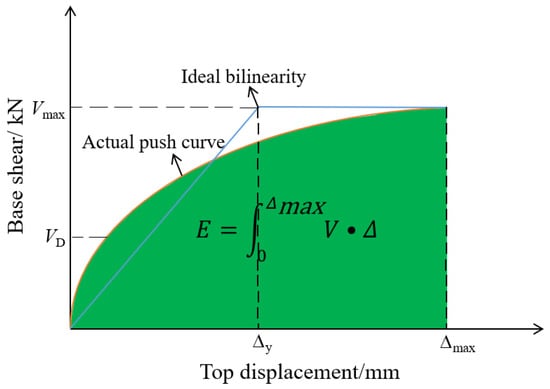
Figure 17.
Energy method for the yield point.
It can be seen from Table 3 that the improvement effect of the replaceable coupling beam on the ductility of the diagrid tube structure is obviously affected by the outer diameter of the diagrid column and the plane form of the structure. With the increase in the outer diameter of the diagrid column, the increase in the ductility coefficient of the diagrid tube structure model with the replaceable coupling beam decreases gradually, which is 24.5%, 16.9%, and 6.4%, respectively. After changing the plane form of the structure from a regular quadrilateral to a regular hexagon, the setting of replaceable coupling beams has a certain reduction in the ductility coefficient of the diagrid tube structure, which is 16.8%, 12.2%, and 2.5%, respectively. In terms of improving the ductility of the diagrid tube structure, the effect of setting a replaceable coupling beam is the best in the structural model with the regular quadrilateral plane and small outer diameter of the diagrid column. Combined with the pushover curves of the 12 structural models, it can be seen that the plane form is a regular quadrilateral and the smaller outer diameter of the diagrid column means that the lateral stiffness of the outer tube of the diagrid is smaller, and the relative stiffness of the inner tube of the shear wall is larger. Therefore, the replaceable coupling beam directly acting on the shear wall improves the ductility of the overall structural model more obviously.
Table 3.
Ductility coefficient changes.
6. Energy Dissipation and Damage Analysis of Diagrid Core-Tube Structure of High-Rise Buildings with Replaceable Steel Coupling Beams
6.1. Selection of Seismic Waves
According to the dual-band wave selection method, that is, the selection of seismic waves is controlled in the two time-domain frequency bands near the [0.1, Tg] platform section and the basic period T1 of the structure. The deviation between the mean acceleration response spectrum of the selected ground motion records in these two sections and the corresponding design response spectrum mean is controlled within 10%. The seismic wave response spectrum is shown in Figure 18 (g is the acceleration, g = m/s2).
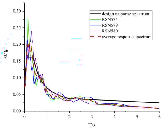
Figure 18.
Seismic wave acceleration response spectrum.
6.2. Energy Analysis under Small Earthquake
The total earthquake input of each structural model under the action of 8-degree small earthquakes (200 gal) can be seen in Table 4 and Figure 19. It can be seen from Figure 19 that with the increase in the outer diameter of the diagrid column of the diagrid tube structure and the change in the structural plane form from the regular quadrilateral to the regular hexagon, the total seismic energy input by the three seismic waves to the structure generally shows a decreasing trend, which is consistent with the relevant research results [33]. Under the same diagrid column diameter and structural plane form, the total seismic energy input to the structure by the three seismic waves changed very little after setting the replaceable coupling beams, indicating that the setting of replaceable coupling beams had no significant effect on the total seismic input energy of the diagrid tube structure under small earthquakes.
Table 4.
Total input energy of the 8-degree small earthquake (×103 kN·m).
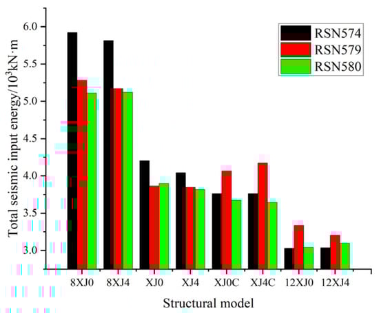
Figure 19.
Total input energy of the 8-degree small earthquake.
The energy time history of each structural model under the action of three seismic waves is similar and in an elastic state. Taking the R574 seismic wave as an example, it can be seen from Figure 20 that the kinetic energy of each structural model at the peak energy is between 2% and 10%, the elastic strain energy is between 80% and 87%, and the damping energy is between 7% and 16%. Under the same diagrid column outer diameter and structural plane form, the setting of the replaceable coupling beam does not affect the energy distribution of the diagrid tube structure under the action of small earthquakes. At this time, the structure is in an elastic state, and the replaceable coupling beam cannot exert its good energy-dissipation capacity.
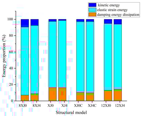
Figure 20.
Energy distribution.
6.3. Large Earthquake Energy Analysis
The total seismic input of each structural model under the action of three seismic waves of an 8-degree earthquake (400 gal) can be seen in Figure 21. It can be seen from Figure 21 that with the increase in the outer diameter of the diagrid column of the diagrid tube structure and the change in the structural plane form from the regular quadrilateral to the regular hexagon, the total seismic energy input to the structure by the RSN574 seismic wave and RSN580 seismic wave gradually decreases, and the total seismic energy input to the structure by the RSN579 seismic wave decreases first and then increases. Under the same diagrid column diameter and structural plane form, the total seismic energy input to the structure by the three seismic waves is very close after setting the replaceable coupling beam, which indicates that setting the replaceable coupling beam has no obvious effect on the total seismic input energy of the diagrid tube structure under the action of large earthquakes.
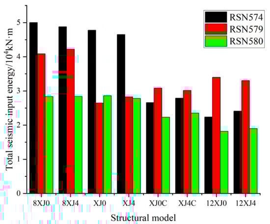
Figure 21.
Total input energy of the 8-degree large earthquake.
From Figure 21, it can be seen that under the same outer diameter of the diagrid column and structural plane form, the setting of the replaceable coupling beam has a significant effect on the energy distribution at the peak energy of the diagrid tube structure under the action of large earthquakes, which shows that the hysteretic energy consumption is greatly improved and the sum of the kinetic energy and elastic strain energy is reduced to a certain extent. This is because compared with the traditional coupling beam, the replaceable coupling beam has more sufficient plastic development and dissipates more energy under the action of large earthquakes.
6.4. Component Energy Dissipation and Diagrid Column Damage
Under the action of three seismic waves, the hysteretic energy-dissipation of each structural model is shown in Figure 22. Under the action of the 8-degree earthquake, the energy-dissipation members of the structure are only diagrid columns and coupling beams, and the shear wall does not enter the plasticity. This is because the shear wall is the last seismic defense line of the diagrid tube structure. After the plastic hinge appears at the foot of the shear wall, the structure will soon lose its stable bearing capacity. If the shear wall enters the plasticity under the action of large earthquakes, it is difficult to ensure that “no collapse under large earthquakes”. From Figure 23, it can be seen that under the action of the same seismic wave, the increase in the hysteretic energy-dissipation of the diagrid tube structure by setting the replaceable coupling beam is manifested as the increase in the energy dissipation of the coupling beam at the component level, while the energy dissipation of the diagrid column is reduced, that is, the plastic damage of the structure under the earthquake is concentrated on the secondary and easy-to-repair components, which protects the main components to a certain extent. The main significance of the replaceable coupling beam is demonstrated in the diagrid tube structure. The outer diameter of the diagrid column and the plane form of the structure have a certain influence on the change in the energy consumption of the diagrid tube structure after setting the replaceable coupling beam. Taking the seismic wave action result of Figure 23a and RSN574 as an example, with the increase in the outer diameter of the diagrid column of the structural model and the change in the plane form of the structure from the regular quadrilateral to the regular 16 deformations, the replaceable coupling beam has an increasing effect on the total hysteretic energy consumption of the structure, which is 2.1 × 10³ kN·m, 3.4 × 10³ kN·m, 4.0 × 10³ kN·m and 4.1 × 10³ kN·m, respectively. The decrease in the hysteretic energy-dissipation of the diagrid column is smaller and smaller, which is 1.5 × 10³ kN∙m, 1.3 × 10³ kN∙m, 0.2 ×10³ kN∙m and 0 × 103 kN∙m, respectively.
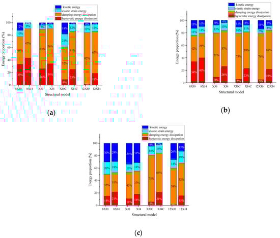
Figure 22.
Energy distribution at the peak energy of the structure under a strong earthquake: (a) RSN574; (b) RSN579; and (c) RSN580.
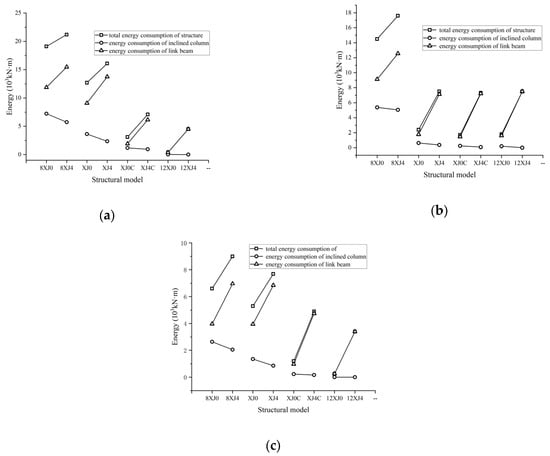
Figure 23.
Distribution and variation of the hysteretic energy-dissipation: (a) RSN574; (b) RSN579; and (c) RSN580.
Figure 24 shows the distribution of the plastic hinges of the diagrid columns of the 8XJ0, 8XJ4, XJ0, and XJ4 structural models at the end of the 8-degree earthquake of the RSN574 seismic wave. Red indicates that the concrete of the diagrid columns reaches yield strain, and yellow, green, and cyan indicate that the fiber strain of diagrid column concrete is 0.9, 0.8, and 0.7 times the yield strain, respectively. It can be seen from Figure 24 that the diagrid column plastic hinges of the XJ0 and XJ4 structural models are mainly distributed in the first and second modules, and the 8XJ0 and 8XJ4 plastic hinges with smaller outer diameters of the diagrid columns are more widely distributed, mainly distributed in the first to fourth modules. In each structural model, the plastic hinges in the flange direction perpendicular to the direction of seismic action are concentrated in the lower one and two modules, and the plastic hinges in the web direction extending from the lower one and two modules to the middle three and four modules. Compared with the traditional coupling beam structure models 8XJ0 and XJ0, the number and range of the diagrid columns with plastic hinges in the 8XJ4 and XJ4 structural models with replaceable coupling beams are smaller, indicating that the setting of replaceable coupling beams can reduce the damage range and degree of diagrid columns of diagrid tube structures after large earthquakes, and so reduce the repair cost.
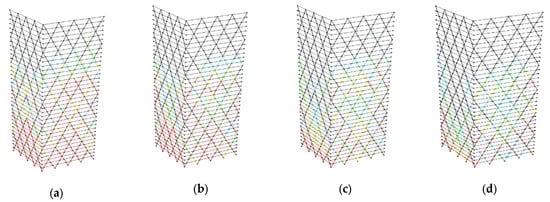
Figure 24.
Plastic hinge distribution of the diagrid column: (a) 8XJ0; (b) 8XJ4; (c) XJ0; and (d) XJ4.
The inter-story drift ratios can be used as an important index to judge the degree of seismic action of the structure. Figure 25 shows the maximum inter-story drift ratios of each story of each structural model during the 8-degree earthquake of the RSN574 seismic wave. It can be seen that in the four groups of comparative models, the maximum inter-story drift ratios of the structural model with replaceable coupling beams are reduced in the process of a large earthquake, which reflects the seismic reduction effect of replaceable coupling beams on the diagrid tube structure.
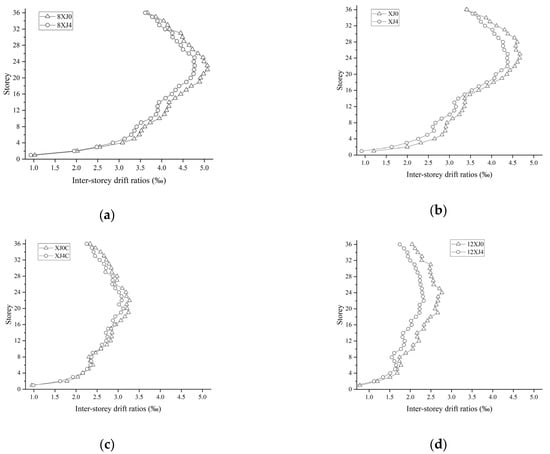
Figure 25.
Comparison of the inter-story drift ratios: (a) 8XJ0 and 8XJ4; (b) XJ0 and XJ4; (c) XJ0C and XJ4C; and (d) 12XJ0 and 12XJ4.
7. Conclusions
In order to consider the sustainability of the diagrid tube structure with replaceable steel coupling beams, this paper comprehensively considers the layout position of replaceable coupling beams, the relative stiffness of inner and outer tubes, and the plane form of the structure. The influence of replaceable coupling beams on the sustainable seismic performance of the diagrid tube structure is discussed by static elastoplastic analysis and seismic response energy analysis. The conclusions are as follows:
- (1)
- The mechanism of the influence of the replaceable coupling beam on the lateral force performance of the diagrid tube structure: the replaceable coupling beam energy-dissipation beam section yields before the traditional coupling beam and its restraint effect on the shear wall is weakened, which affects the lateral stiffness of the inner tube of the shear wall, the speed of internal force growth, and the yield time, thereby affecting the lateral elastic–plastic stress state of the overall structure.
- (2)
- From the point of view of improving the ductility and sustainability of the diagrid tube structure and reducing the economic cost of post-earthquake repair, replaceable coupling beams should be set on the whole floor.
- (3)
- Replaceable coupling beams make the hysteretic energy-dissipation of the diagrid tube structure appear earlier under the action of an 8-degree earthquake, and the proportion of hysteretic energy-dissipation is greatly improved, which reduces the inter-story drift ratios of each floor and the damage degree of the diagrid column during the action of a large earthquake. When the relative stiffness of the outer tube of the diagrid tube structure is small or the plane form of the structure is a regular quadrilateral, the application of replaceable coupling beams is more effective in improving the ductility and sustainability of the structure and reducing the damage to the diagrid column under large earthquakes.
Nevertheless, this study inevitably possesses certain limitations. Firstly, the research primarily concentrates on static elastoplastic and seismic response energy analysis, without delving into dynamic responses under real earthquake conditions or more intricate nonlinear behaviors. Secondly, to ensure the feasibility of this study, some simplifications and abstractions of the actual structure may have been necessary during the analytical process, which could potentially influence the precision of the results.
Author Contributions
Conceptualization, C.L.; methodology, G.L.; software, B.H.; validation, C.Z.; formal analysis, Y.M. All authors have read and agreed to the published version of the manuscript.
Funding
This work was supported by the National Natural Science Foundation of China under Grant 51778538, the Yunnan Water Resources and Hydropower Vocational College Foundation under Grant 2023SZYKL009, and by the China Scholarship Council under Grant 201707005100.
Institutional Review Board Statement
Not applicable.
Informed Consent Statement
Not applicable.
Data Availability Statement
Data are contained within the article.
Acknowledgments
The authors would like to acknowledge and express their gratitude to all the people who helped complete this research and to the editors and reviewers for their suggestions for improving the manuscript.
Conflicts of Interest
The authors declare no conflict of interest.
References
- Bhat, K.A.; Danish, P. Analyzing different configurations of variable angle diagrid structures. Mater. Today Proc. 2020, 42, 821–826. [Google Scholar] [CrossRef]
- Liu, C.; Fang, D.; Zhao, L.; Zhou, J. Seismic fragility estimates of steel diagrid structure with performance-based tests for high-rise buildings. J. Build. Eng. 2022, 52, 104459. [Google Scholar] [CrossRef]
- Liu, C.; Fang, D.; Zhao, L. Reflection on earthquake damage of buildings in 2015 Nepal earthquake and seismic measures for post-earthquake reconstruction. Structures 2021, 30, 647–658. [Google Scholar] [CrossRef]
- Song, S.; Zhang, C. Lateral stiffness and preliminary design methodology of twisted diagrid tube structures. Struct. Des. Tall Spéc. Build. 2020, 29, e1809. [Google Scholar] [CrossRef]
- Scaramozzino, D.; Albitos, B.; Lacidogna, G.; Carpinteri, A. Selection of the optimal diagrid patterns in tall buildings within a multi-response framework: Application of the desirability function. J. Build. Eng. 2022, 54, 104645. [Google Scholar] [CrossRef]
- Yang, J.; Duan, S.; Li, Q.; Liu, C. A review of flexible protection in rockfall protection. Nat. Hazards 2019, 99, 71–89. [Google Scholar] [CrossRef]
- Liu, C.; Zhao, B.; Yang, J.; Yi, Q.; Yao, Z.; Wu, J. Effects of brace-to-chord angle on capacity of multi-planar CHS X-joints under out-of-plane bending moments. Eng. Struct. 2020, 211, 110434. [Google Scholar] [CrossRef]
- Heshmati, M.; Khatami, A.; Shakib, H. Seismic performance assessment of tubular diagrid structures with varying angles in tall steel buildings. Structures 2020, 25, 113–126. [Google Scholar] [CrossRef]
- Moon, K.S. Optimal Configuration of Structural Systems for Tall Buildings. In Proceedings of the 20th Analysis and Computation Specialty Conference, Chicago, IL, USA, 29–31 March 2012. [Google Scholar] [CrossRef]
- Shi, Q.X.; Zhang, F. Simplified calculation of shear lag effect for high-rise diagrid tube structures. J. Build. Eng. 2019, 22, 486–495. [Google Scholar] [CrossRef]
- Leonard, J. Investigation of Shear Lag Effect in High-Rise Buildings with Diagrid System. Ph.D. Thesis, Massachusetts Institute of Technology, Cambridge, UK, 2007. [Google Scholar]
- Roshani, M. Performance assessment and calculation of robustness of high-rise diagrid tube structures with various configurations. Structures 2023, 54, 898–917. [Google Scholar] [CrossRef]
- Li, T.X.; Yang, T.Y.; Tong, G.S. Study on energy dissipation mechanism and seismic performance of diagrid structure with double lines of defense recoverable performance. World Earthq. Eng. 2019, 35, 37–44. (In Chinese) [Google Scholar]
- Farsi, A.; Keshavarzi, F.; Pouladi, P.; Mirghaderi, R. Experimental study of a replaceable steel coupling beam with an end-plate connection. J. Constr. Steel Res. 2016, 122, 138–150. [Google Scholar] [CrossRef]
- Shahrooz, B.M.; Fortney, P.J.; Harries, K.A. Steel Coupling Beams with a Replaceable Fuse. J. Struct. Eng. 2018, 144, 04017210. [Google Scholar] [CrossRef]
- Ji, X.D.; Wang, Y.D.; Ma, Q.F.; Qian, J.R. Experimental study on seismic performance of replaceable steel coupling beams. J. Build. Struct. 2015, 36, 1–10. (In Chinese) [Google Scholar]
- Chao, S.-H.; Almasabha, G.; Price, B.; Jiansinlapadamrong, C. A horizontal stiffener detailing for shear links at the link-to-column connection in eccentrically braced frames. J. Struct. Eng. 2023, 149, 04023114. [Google Scholar] [CrossRef]
- Almasabha, G.; Al-Mazaidh, R. Simple Truss Model to estimate the shear strength of short links in the Eccentrically Braced Frame (EBF) steel system. Thin-Walled Struct. 2023, 188, 110811. [Google Scholar] [CrossRef]
- Almasabha, G.; Alshboul, O.; Shehadeh, A.; Almuflih, A.S. Machine learning algorithm for shear strength prediction of short links for steel buildings. Buildings 2022, 12, 775. [Google Scholar] [CrossRef]
- Almasabha, G. Gene expression model to estimate the overstrength ratio of short links. Structures 2022, 37, 528–535. [Google Scholar] [CrossRef]
- Almasabha, G.; Chao, S.H. A New Reinforcing Configuration for Achieving High-Ductility and High-Strength Rectangular Squat Structural Walls. ACI Struct. J. 2023, 120, 253. [Google Scholar] [CrossRef]
- ANSI/AISC 341-10; Seismic Provisions for Structural Steel Buildings. American Institute of Steel Construction: Chicago, IL, USA, 2010.
- Qu, Z.; Ji, X.; Shi, X.; Wang, Y.; Liu, H. Cyclic loading test of steel coupling beams with mid-span friction dampers and RC slabs. Eng. Struct. 2019, 203, 109876. [Google Scholar] [CrossRef]
- Chen, Y.; Li, J.; Lu, Z. Experimental Study and Numerical Simulation on Hybrid Coupled Shear Wall with Replaceable Coupling Beams. Sustainability 2019, 11, 867. [Google Scholar] [CrossRef]
- Christopoulos, C.; Montgomery, M. Viscoelastic coupling dampers (VCDs) for enhanced wind and seismic performance of high-rise buildings. Earthq. Eng. Struct. Dyn. 2013, 42, 2217–2233. [Google Scholar] [CrossRef]
- Liu, C.Q.; Ma, K.Q.; Wei, X.D.; He, G.J.; Shi, W.X.; Zhou, Y. Shaking Table Test and Time-history Analysis of High-rise Diagrid Tube Structure. Period. Polytech.-Civ. Eng. 2017, 61, 300–312. [Google Scholar] [CrossRef]
- Ling, Y.; Zhang, H.; Zhou, J. Research on the Overstrength Performance of Lateral Force-Resisting System of Guangzhou West Tower Based on Story Overturning Moment. J. Earthq. Eng. 2023, 1–30. [Google Scholar] [CrossRef]
- Wang, B.; Shi, Q.; Cai, W. Seismic behavior and damage assessment of concrete-filled steel tube columns in diagrid structures. Struct. Des. Tall Spéc. Build. 2021, 31, e1904. [Google Scholar] [CrossRef]
- Hou, H.; Wang, W.; Zhang, Y. Seismic damage assessment for flexural double skin composite walls based on the modified Park-Ang model. Thin-Walled Struct. 2023, 196, 111445. [Google Scholar] [CrossRef]
- GB50010-2010; Concrete Structure Design Code. China Construction Industry Press: Beijing, China, 2010.
- Zhong, S.T. Concrete Filled Steel Tubular Structures; Tsinghua University Press: Beijing, China, 2003. [Google Scholar]
- Mander, J.B.; Priestley, M.J.N.; Park, R. Theoretical Stress-Strain Model for Confined Concrete. J. Struct. Eng. 1988, 114, 1804–1826. [Google Scholar] [CrossRef]
- Cheng, Y.; Dong, Y.-R.; Qin, L.; Wang, Y.-Y.; Li, Y.-X. Seismic Energy Response of SDOF Systems Subjected to Long-Period Ground Motion Records. Adv. Civ. Eng. 2021, 2021, 6655400. [Google Scholar] [CrossRef]


Disclaimer/Publisher’s Note: The statements, opinions and data contained in all publications are solely those of the individual author(s) and contributor(s) and not of MDPI and/or the editor(s). MDPI and/or the editor(s) disclaim responsibility for any injury to people or property resulting from any ideas, methods, instructions or products referred to in the content. |
© 2024 by the authors. Licensee MDPI, Basel, Switzerland. This article is an open access article distributed under the terms and conditions of the Creative Commons Attribution (CC BY) license (https://creativecommons.org/licenses/by/4.0/).