Article

Evaluation of Kunkur Fines for Utilization in the Production of Ternary Blended Cements

by
Victor Kiptoo Mutai
1,2,
Joseph Mwiti Marangu
1,
Cyprian Muturia M’Thiruaine
1 and
Luca Valentini
2,*
1
Department of Physical Sciences, Meru University of Science & Technology, Meru 60200, Kenya
2
Department of Geosciences, University of Padua, 35126 Padova, Italy
*
Author to whom correspondence should be addressed.
Sustainability 2023, 15(23), 16453; https://doi.org/10.3390/su152316453
Submission received: 4 October 2023 / Revised: 27 November 2023 / Accepted: 28 November 2023 / Published: 30 November 2023

Abstract

:
Ternary blended cements, such as limestone calcined clay cement (LC3), represent a type of strategic binder for the mitigation of environmental impacts associated with cement production. These are estimated to reduce CO2 emissions by about 40% compared to ordinary Portland cement (OPC). In this paper, we explore the possibility of producing such ternary blends by utilizing secondary raw materials that may be locally available. Specifically, the primary limestone that is commonly used in LC3 is herein substituted with quarry dust obtained by sourcing “kunkur”, a carbonate-rich sedimentary rock (also known as caliche) that can be locally utilized for the production of ordinary OPC clinker. To optimize the blending proportions of ternary cement consisting of OPC, calcined clay, and kunkur fines, a “design of experiment” (DoE) approach was implemented with the goal of exploring the possibility of reducing the amount of the OPC fraction to values lower than 50%. The properties of the formulated blends were assessed by a combination of techniques that comprise mechanical strength testing, XRD time-dependent quantitative phase analysis, and SEM–EDS microstructural and microchemical analyses. The results suggest that ternary blended cement based on kunkur fines forms hydration products, such as hemicarboaluminates, which are also observed in LC3. This shows that such waste materials can potentially be used in sustainable cement blends; however, the presence of kaolinite in the kunkur fines seems to affect their strength development when compared to both OPC and conventional LC3.

1. Introduction

The production of Portland cement generates an estimated carbon footprint corresponding to 6–10% of global emissions [1]. This has an impact on global efforts to address climate change and other related environmental concerns [2]. Using alternative binders to reduce the consumption of Portland cement in concrete constructions is considered to be one of the viable options for a sustainable construction industry [3,4]. The most promising achievable option is through cement dilution, i.e., by replacing a fraction of ordinary Portland cement (OPC) with powders having different degrees of reactivity, the most common being fly ash, ground granulated blast furnace slags, calcined clay, and finely ground limestone. These filler materials may be inert or reactive in the cement hydration process [3,5]. When displaying some degree of reactivity in blends with OPC, they are commonly known as supplementary cementitious materials (SCMs) and have the potential to reduce the amount of emitted CO2 per unit mass of binder [4]. With the various options in which these materials are utilized to produce different concretes, the aspects of familiarity, versatility, strength, durability, wide availability, fire resistance, resistance to the elements, and comparatively low cost remain key factors to be considered [6]. The use of filler materials to substitute the clinker considerably meets these requirements [7].
Among the different possible approaches to the use of SCMs in blended cement, limestone calcined clay cement (LC3) represents a promising binder, with the potential to reduce global CO2 emissions in the atmosphere by about 40% due to clinker replacing up to about 45% [8,9]. In its most common formulation, LC3 incorporates 50 wt.% OPC clinker, 30 wt.% calcined clay (CC), 15 wt.% limestone (LS), and 5 wt.% gypsum (Gy). Several advantages have been reported from the pilot trials implemented across the world [10,11,12]. According to [10], a high-strength LC3 binder, comparable to OPC after 28 days, can be produced with calcined clays having a kaolinite content as low as 40%. This provides the considerable option of using impure kaolinitic clays in LC3 production [11]. Further, low-grade limestone can also be used [12,13,14]. The synergy between limestone and calcined clay enhances the engineering properties, with a great potential to reduce the clinker fraction to about 50% [15]. Similarly, the lower embodied energy is advantageous compared to OPC production. For example, optimal temperatures not exceeding 900 °C are needed in the clay calcination process [16,17,18]. Other studies also show a possible lower temperature requirement, with a higher pozzolanic activity, when other mineral materials such as dolomite are co-calcined with clay [11,19].
The incorporation of other filler materials into similar ternary blends is also possible. This allows, for example, industrial and agricultural waste materials to be utilized. Such waste includes rice husk ash (RHA), broken fired bricks, and ceramic wastes, among others [20,21,22]. Previous studies also show that filler materials such as limestone can accelerate the early rate of hydration [2,23,24]. This effect can be accounted for by two phenomena: (1) the filler materials provide an increased surface area, which then enables an enhanced heterogeneous nucleation of the hydration products, and (2) an enhanced water availability per unit mass of cement particles (i.e., w/c increase or dilution) [25,26,27]. The improved early age properties therefore lead to better binder performance.
Generally, most studies explored the incorporation of different types of filler materials in blended cement. Several concerns such as compromise in the performance of cement due to the poor development of cementing properties have been reported before, depending on the nature and amount of the additions [28,29]. Similarly, the utilization of calcined clays and further extension of clinker substitution rates were hindered by such concerns [30]. However, most challenges such as reduced workability, high water demand in concrete mixtures, and delayed strength development can now be addressed by the use of superplasticizers and other admixtures [31,32,33]. These recent advancements expand the scope of SCMs and fillers, as well as their utilization in blended cements. With this realization, a better understanding of the different fillers is possible. Further, a potentially viable implementation of sustainable mixture designs can be optimized to allow for an increased substitution of the clinker fraction [34,35].
The present study aims to investigate the potential of utilizing “kunkur”, a nodular calcium carbonate rock formed in semi-arid regions, which is also commonly known as “caliche” or “calcrete”. These are naturally cemented soils formed due to the evaporation of water containing dissolved calcium carbonate [36]. They are composed of small calcite crystals and other minerals that are commonly found in soils, and hence have found several applications in cement production and road construction [37,38,39].
For example, in Kenya, “kunkur” has been used in cement production [40,41]. However, the fines formed by the quarrying of “kunkur” have not been so far utilized as they are considered wastes and are commonly stockpiled. Due to the significant calcite content and its wide availability in specific locations, kunkur fines may represent a suitable candidate for replacing primary limestone in ternary blends. To the best of our knowledge, neither primary caliche nor “kunkur” fines, sourced as waste from caliche quarrying, have ever been utilized in blended cements. This study therefore explored the potential of utilizing kunkur fines in belnded cements, as a substitute of primary limestone, in achieving a higher clinker fraction substitution and improved ternary cement performance, using a “design of experiment” (DoE) approach. This research, therefore, has the goal of addressing the underutilization of a readily available secondary material, with the potential to reduce environmental impacts and improve the efficiency of cement manufacturing.

2. Materials and Experimental Methods
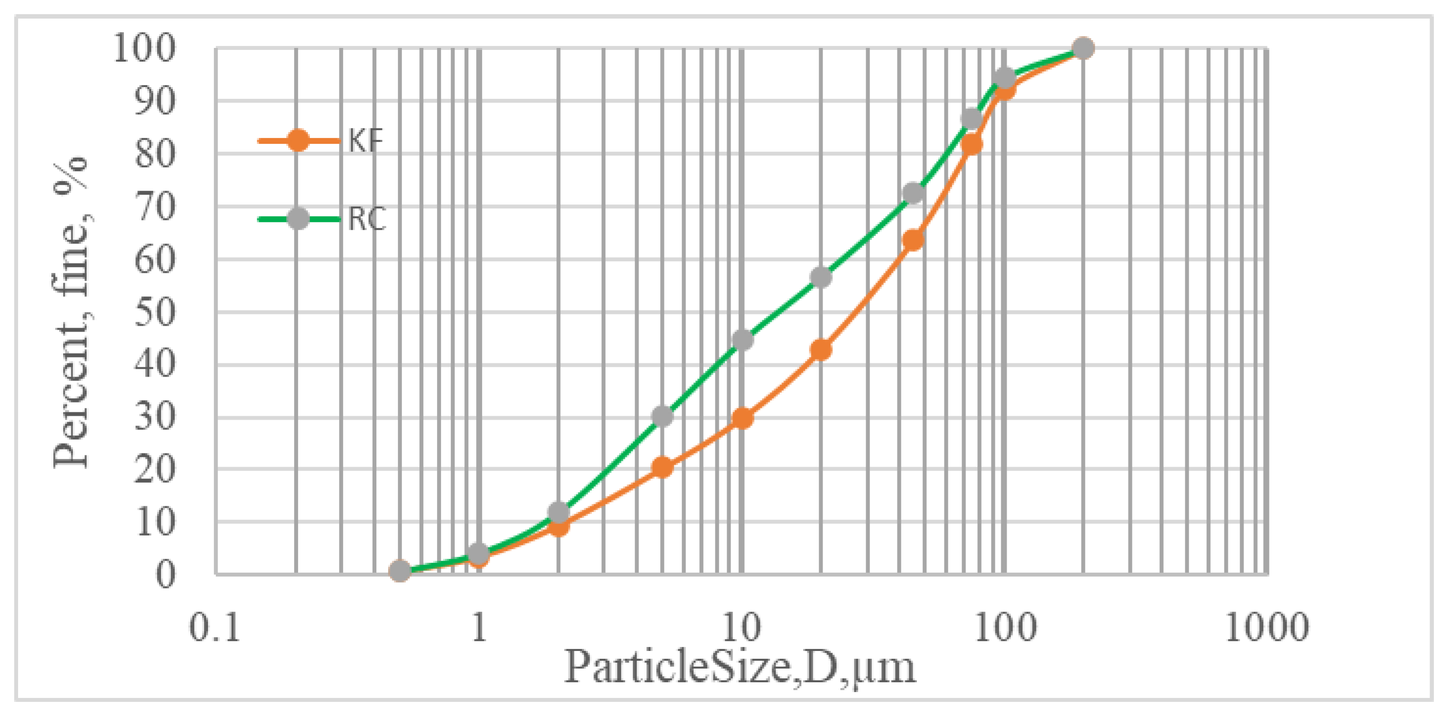
2.1. Materials

OPC clinker (CL) and industrial-grade gypsum powder (Gy) were used as reference materials to prepare the ternary blends. The kunkur fines (KFs) were obtained from the East African Portland Cement Company (EAPCC). The raw clay (RC) was sourced in Nandi County (1.3973°, 34.4489°), Kenya. The particle size distribution (PSD) of KFs and RC (Figure 1) was measured by laser scattering using a Bettersizer SD particle size analyzer (LS13-320; Bettersize Instruments Ltd., Dandong, China). A muffle furnace was used to calcine the raw clay at 800 °C for 2 h. Standard sand (CEN Standard Sand EN 196-1:2016) [42] was used to cast the mortars.

2.2. Methods

2.2.1. Chemical Composition

The chemical composition of the utilized materials was obtained by X-ray fluorescence (XRF, Siemens COROS OP15, Plano, Texas, U.S.) following the standard procedure according to [43], describing the minimum oxide that the samples should contain. Laboratory grinding was carried out using a HERZOG (Osnabruck, Germany) laboratory ball mill FLS 1480, T0200 (1996) with 1480/38 RPM. To ensure homogeneity, the samples were passed through a 100 μm sieve. Homogeneous pellets were obtained using 12 g of sample mixed with a binding agent (wax) and a hand-pressing machine operated at 20 tonnes.
The XRF chemical composition of the starting materials is displayed in Table 1.

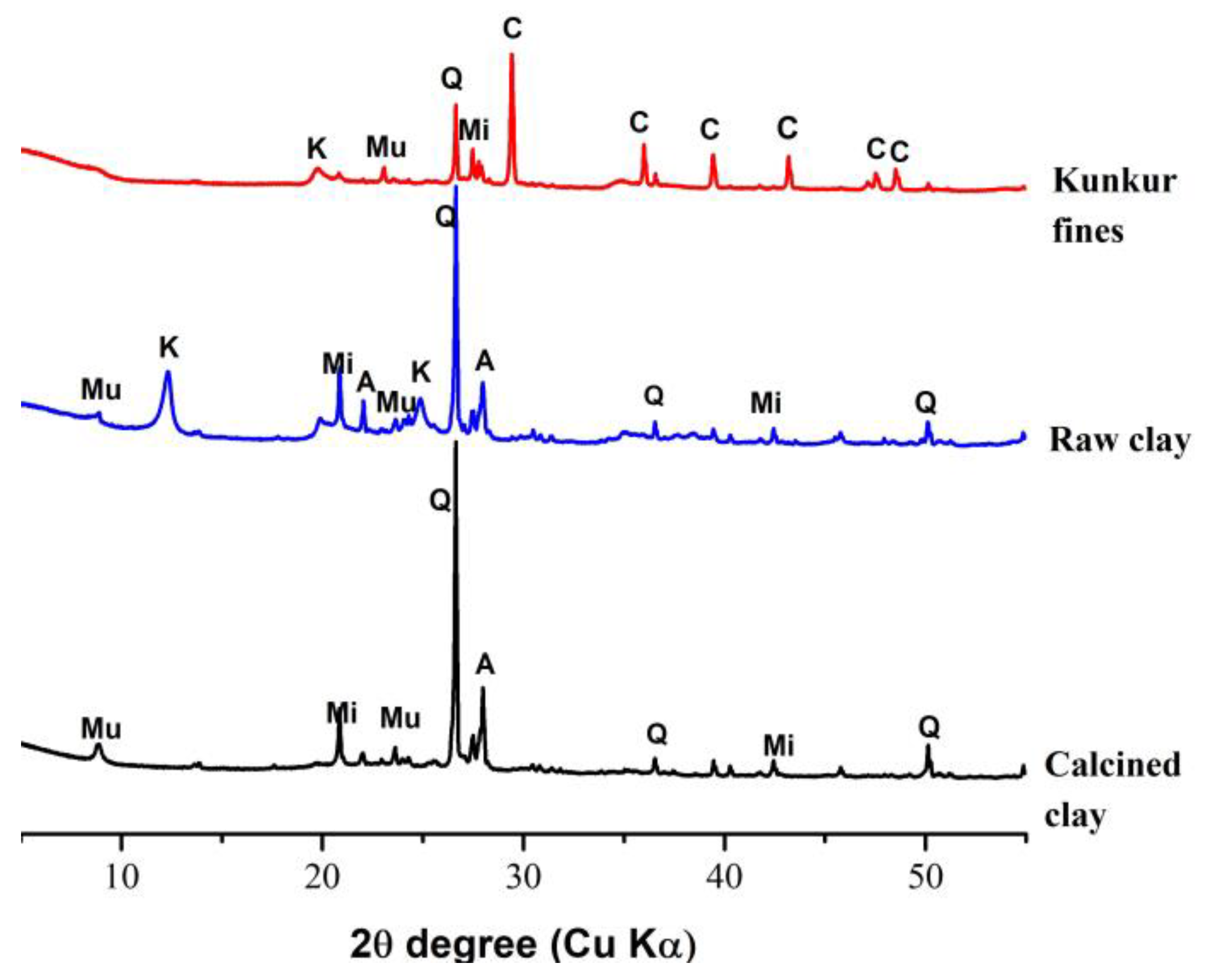
2.2.2. Mineralogical Composition of Raw Materials and Reacted Mixtures

The samples for XRD mineralogical analysis were prepared by hand-grinding to obtain powders of sizes less than 75 μm. Subsequently, the samples were micronized in a grinding jar filled with zirconium oxide elements. About 4 mL ethanol was added and the samples were ground using a McCrone Micronizer for 5 min. The obtained suspension was dried and flat samples were prepared by backfilling to avoid preferred orientation. This procedure was repeated for the XRD analysis of the raw samples and the reacted mixtures using a PANalytical X’Pert PRO diffractometer, in Bragg–Brentano geometry. Diffraction patterns were collected in the 3°–85° 2θ range, with 0.017° 2θ step size and equivalent time of 100 s per step. From the XRD analysis, clinker was determined to have a phase composition of 54.9% C3S, 17.7% C2S, 6.6% C3A, and 10.7% C4AF. The XRD patterns of the other starting materials are shown in Figure 2. From the results, the major phases observed in the kunkur fines are calcite, kaolinite, muscovite, feldspar (microcline), and quartz, compatible with the genesis of these kinds of materials, which consist of soils cemented by calcium carbonate, which is precipitated by evaporation. The raw clay mainly consists of kaolinite and quartz, with other minor phases such as muscovite, albite, and microcline. The XRD pattern of the clay calcined at 800 °C shows the disappearance of the kaolinite peaks upon structural collapse of this phase.

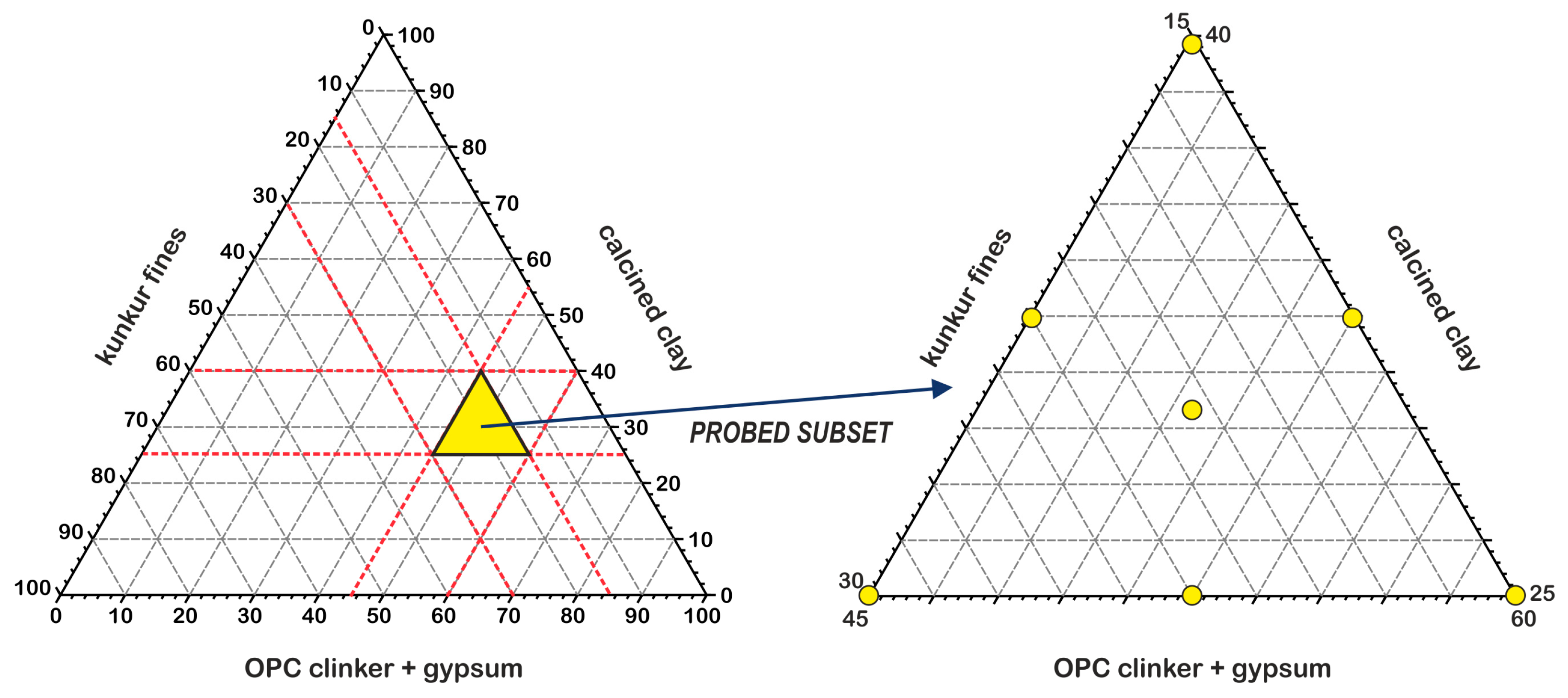
2.2.3. Mixture Design

In the study, a three-component mixture design (simplex centroid design) was used to obtain an efficient and structured approach to examine the KF influence, potential, and suitability for utilization to reduce the clinker fraction in cement. This method allows for the treatment of the sample as a sum of all the components adding up to 1 (or 100%); hence, the synergy effect of the variation of the ratios among the variables (KF, CC, and CL) is possible [44]. The effect of the KFs on the behavior of ternary blends is screened by determining the performance of the binder in terms of compressive strength of the cast cement pastes at various curing days.
The experimental design used consists of the probed subset in the mixture space (Figure 3), where each variable is fixed at the lower and upper levels of the mixture space explored. The experimental mixture space covered a range from 40 to 55%, 15 to 30%, and 25 to 40% for CL, KF, and CC, respectively, whereas the amount of gypsum was kept constant at 5%. For reference, Portland cement with composition meeting CEM I type was prepared following the standard specified in [45]. The experiments were performed according to the mixture composition for the experimental points in Figure 3 and their responses (the compressive strengths for the respective curing days) reported, based on a linear mathematical equation (Equation (1)). The equation describes the influence of the main factors (KF, CC, and CL) and their interactions with respect to the response parameter Y (compressive strength):
Y = b 1 X 1 + b 2 X 2 + b 3 X 3 + b 12 X 1 X 2 + b 13 X 1 X 3 + b 23 X 2 X 3 + b 123 X 1 X 2 X 3
In this equation, X1, X2, and X3 correspond to the amount of the clinker, kunkur fines, and calcined clay, normalized between 0 and 1. The value of the coefficients bn is calculated by setting a system of seven equations, each corresponding to an experimental run, with seven unknowns.

2.2.4. Compressive Strength

Cement pastes for these mixtures were prepared using potable water at a fixed water-to-cement ratio (w/c = 0.5) using a planetary mixer (IKA, Staufen, Germany) as described in [46]. The selected w/c ratio ensured a proper workability in the presence of mineral phases such as kaolinite and metakaolinite, without the addition of superplasticizers. No signs of segregation or bleeding were observed. The cement paste mixtures were prepared according to the proportions shown in Table 2. “S1” to “S7” correspond to the seven-mixture design experimental points displayed in Figure 3, whereas “S8” is the OPC control mix. The pastes were cast in prisms of 1.5 cm × 1.5 cm × 6 cm and demolded after 48 h, wrapped in a slightly wet cloth, and put in sealable plastic bags until the day of the test. The compressive strength was determined using a compressive strength test machine (Controls, Model 82-P0374) after 2, 7, and 28 days of curing.

2.2.5. DoE Model Validation

To validate the modeled responses, three points from the mixture space matching cement pastes showing the lowest, medium, and highest (mixing proportions in Table 3) performance in terms of compressive strength in the design were prepared. After selecting the validated formulation with the highest compressive strength, an automatic mixer (AUTOMIX, Controls model no. 65-L0006/AM) was used to prepare mortars according to EN196-1. OPC paste and mortar controls were also prepared for reference.

2.2.6. Scanning Electron Microscopy (SEM)

Fragments of the samples tested for compressive strength were kept for SEM microstructural analysis. Hydration was stopped by solvent exchange, by soaking the samples in ethanol for one week. The samples were pre-polished, cast in epoxy resin within plastic molds, and cured at 40 °C for 24 h. Subsequently, final polishing was performed on a lap wheel to achieve a desired cross-section of the material and coated with carbon to improve conductivity during analysis. The instrument used in the study was a TESCAN SOLARIS FE-SEM, in backscattered electron (BSE) mode, operated in high vacuum at 10 KeV energy, 3 nA current intensity, and 5 mm working distance. Energy-dispersive X-ray (EDX) was used to assess the microchemical composition of the hardened pastes.

3. Results and Discussion

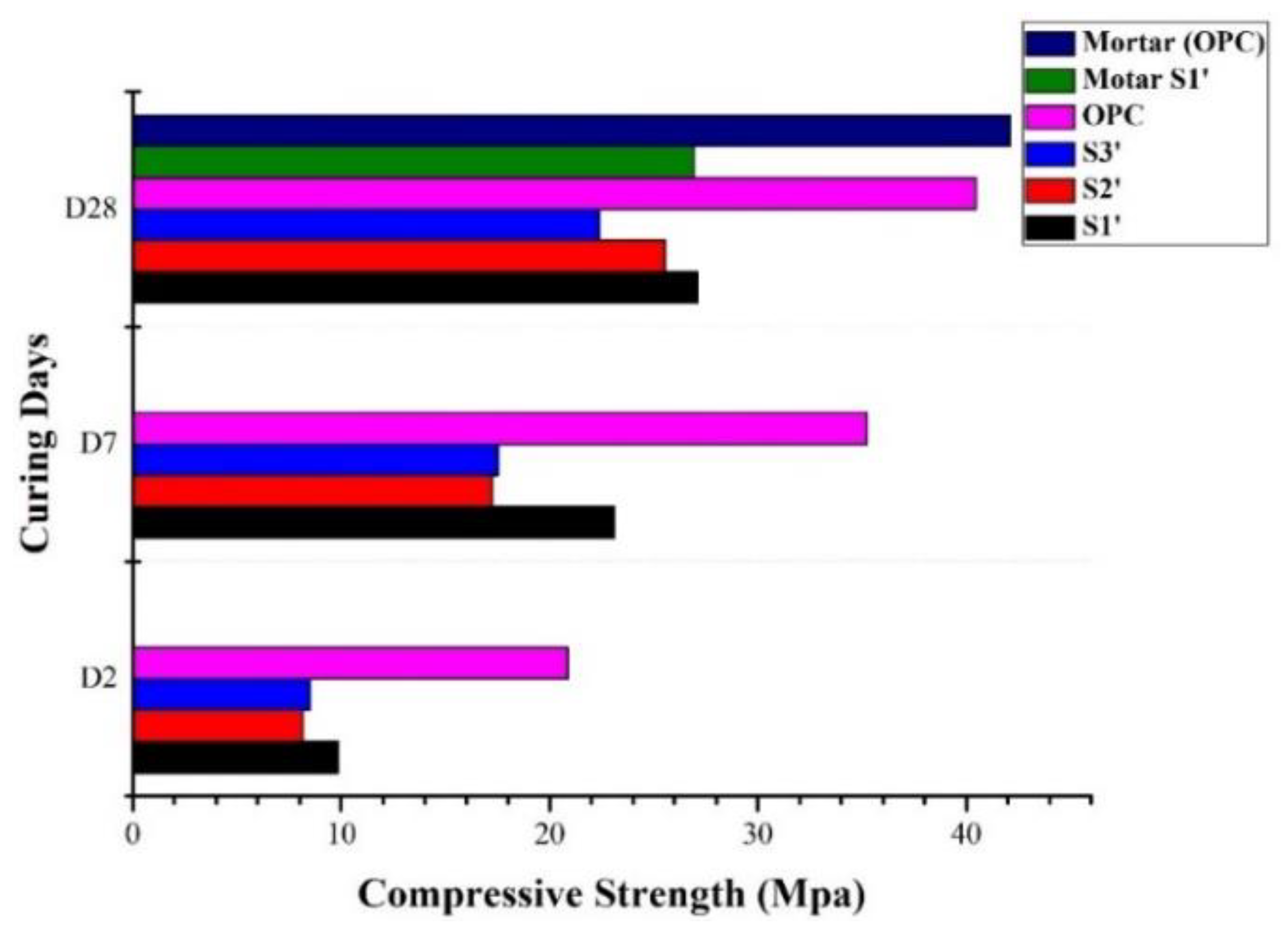
3.1. Compressive Strength

The isoresponse plots of the mixture design are shown in Figure 4. These plots display the variation of the compressive strength (2, 7, 28 days) with the binder composition, obtained by interpolating the model equation (Equation (1)).
From the plot in Figure 4, it can be observed that the compressive strength after 2 days was majorly influenced by the presence of the clinker and the calcined clay. The highest strength was predicted to have been above 10 MPa. The major phases, C3S, C2S, and C3A, underwent a faster reaction as compared to pozzolanic materials, which are known to start reacting after the second day [47]. This fact can be demonstrated on day 7, where it was observed that the influence of the clinker and CC became significant. With the additional CC, the compressive strength achieved was about 20.5 MPa compared to a strength of about 17 MPa with the clinker. KFs were also seen to contribute to the mechanical performance to some extent. The highest strength on day 7 was predicted to have been at above 21 MPa. The influence of KFs starting from day 7 suggests a slow dissolving nature of the calcite content in the KFs, as typically observed [48].
Finally, at 28 days, the compressive strength was observed to have been influenced by the presence of the highest amount of CC present in the blend. This can be attributed to the role of the pozzolanic reaction. These observations are consistent with previous studies that suggested that the reaction of metakaolin in blended cement occurs at a later age of hydration [49]. Additionally, the major clinker phases react faster at early age, leaving a smaller amount available for further reaction at later stages of hydration. The highest predicted compressive strength is approximately 34 MPa for the mix consisting of 40% CL, 5% Gy, 40% CC, and 15% KFs. The strength predicted is lower by about 20% as compared to the control OPC, which has a mechanical strength of about 42.5 MPa.

3.2. DoE Model Validation

The compressive strength of the blends reported in Table 2, as well as that of the 28 days mortar samples, is displayed in Figure 5.
In general, these results confirm the trend predicted by the DoE model, i.e., in the studied compositional range, the strength is maximized proportionally to the amount of calcined clay. The measured strength tends to be significantly lower compared to the control OPC samples, which can be ascribed to the high level of substitution of the studied samples. The values of compressive strength measured on mortars at 28 days were in line with those measured for the corresponding cement pastes. A comparable strength is observed in S1′, which attained a strength of 26.94 MPa in the mortar sample and 27.09 MPa for the cement paste sample. This behavior was consistent for all the samples tested.
The dilution effect reduces the amount of portlandite available for pozzolanic reaction due to reduced clinker in the cement. In addition, the pozzolanic materials could not compensate for the loss in strength performance due to the slow rate of the pozzolanic reaction, which continues beyond the 28 days of curing [32]. The lower strength could also be partly attributed to the challenges with compaction experienced during the casting of the blended cement mortar due to the high water demand of the calcined clay [10]. The addition of superplasticizers (which was not envisaged in this study to avoid an excessively high number of variables in the studied system) may likely improve the strength of mortars with a high content of calcined clay, similar to the one formulated in this study.

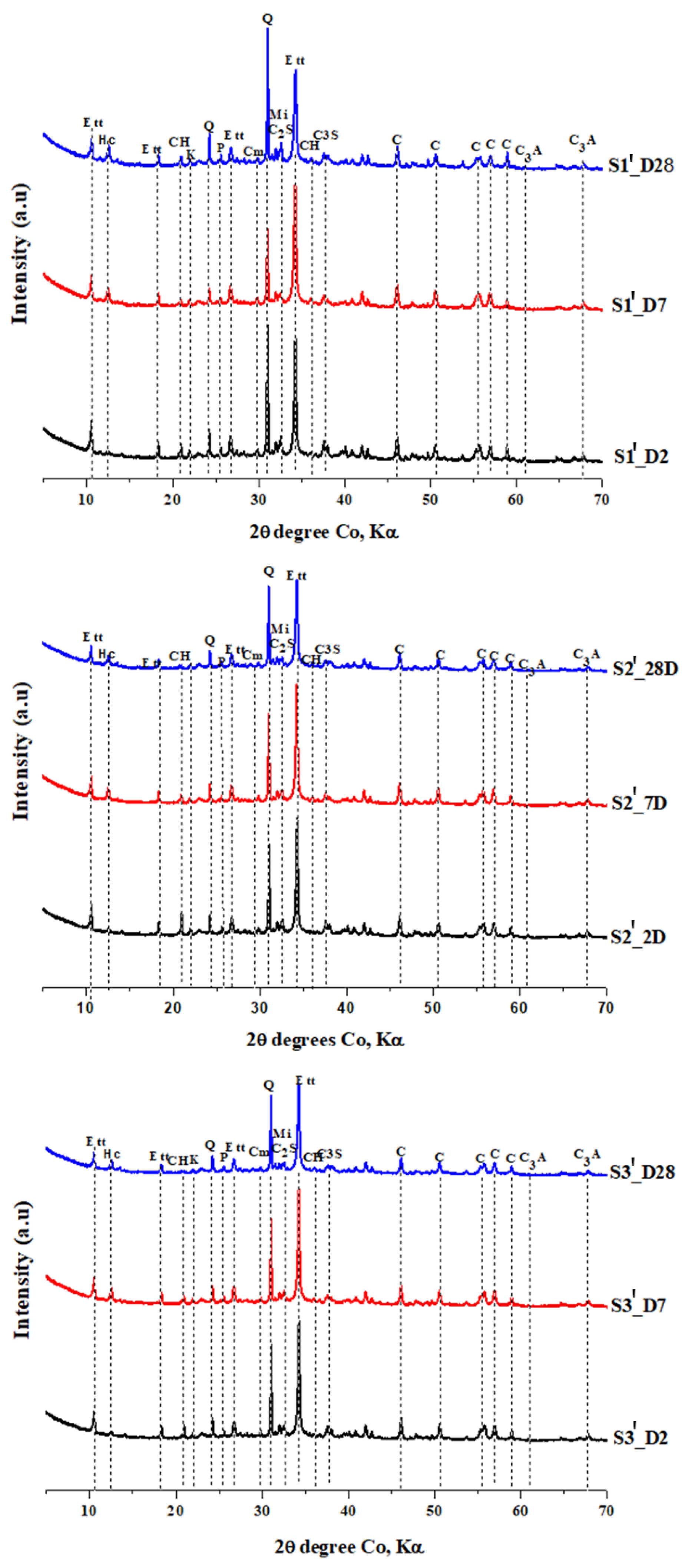
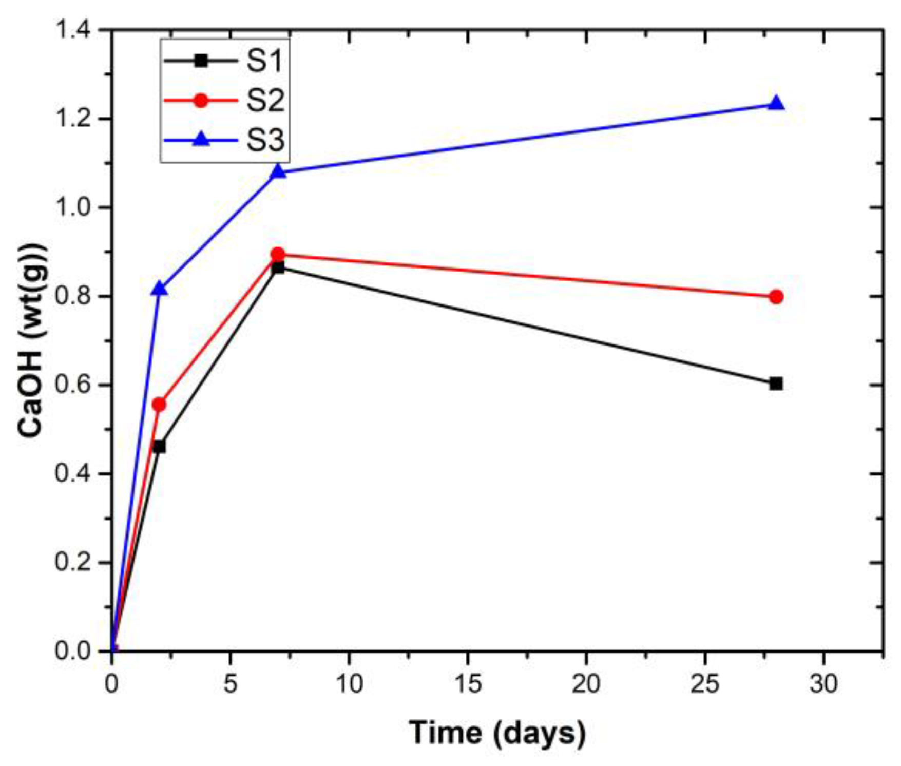
3.3. XRD Analysis of the Hardened Pastes

In order to assess the role of the hydration products’ precipitation kinetics on the macroscopic properties of the studied mixtures, XRD was performed at 2, 7, and 28 curing days. The XRD patterns of the cement pastes are presented in Figure 6 for the 2Ɵ region between 5° and 70°.
It can be observed that the main phases present in all samples include clinker phases; kaolinite, quartz, and microcline deriving from the kunkur fines and calcined clay; portlandite, ettringite, and hemicarboaluminate as reaction products. The intensity of the calcite peaks does not vary significantly over time, suggesting that the partial dissolution of the calcite present in the kunkur fines is compensated by the carbonation of the reaction products [50].
Figure 7 demonstrates the difference in pozzolanic activity for S1′, S2′, and S3′. It can be observed that the pozzolanic activity decreases from S1′ to S3′. The highest activity in S1′ can be attributed to the highest amount of amorphous silica from CC, leading to pozzolanic reaction with CH.
The other minerals, including feldspar, kaolinite, and calcite, do not seem to have a significant change in their peak intensity. Phases such as feldspars mostly act as physical fillers. With respect to calcite, the formation of hemicarboaluminate (Hc) shown by the peak at 2Ɵ = 12.560 indicates some extent of calcite dissolution, which reacts with the aluminum ions released by the dissolution of the amorphous aluminosilicate fraction in the CC, in agreement with previous studies [51]. The Hc peak is observed to gradually increase with curing time. According to [51], the precipitation of hemicarboaluminate exerts a direct effect on pore refinement and strength development beyond 28 days of hydration. The formation of AFm was not detected in any of the samples at all curing ages. This confirms that the formation of hemicarboaluminate stabilized ettringite and hindered the formation of monosulfate [47].

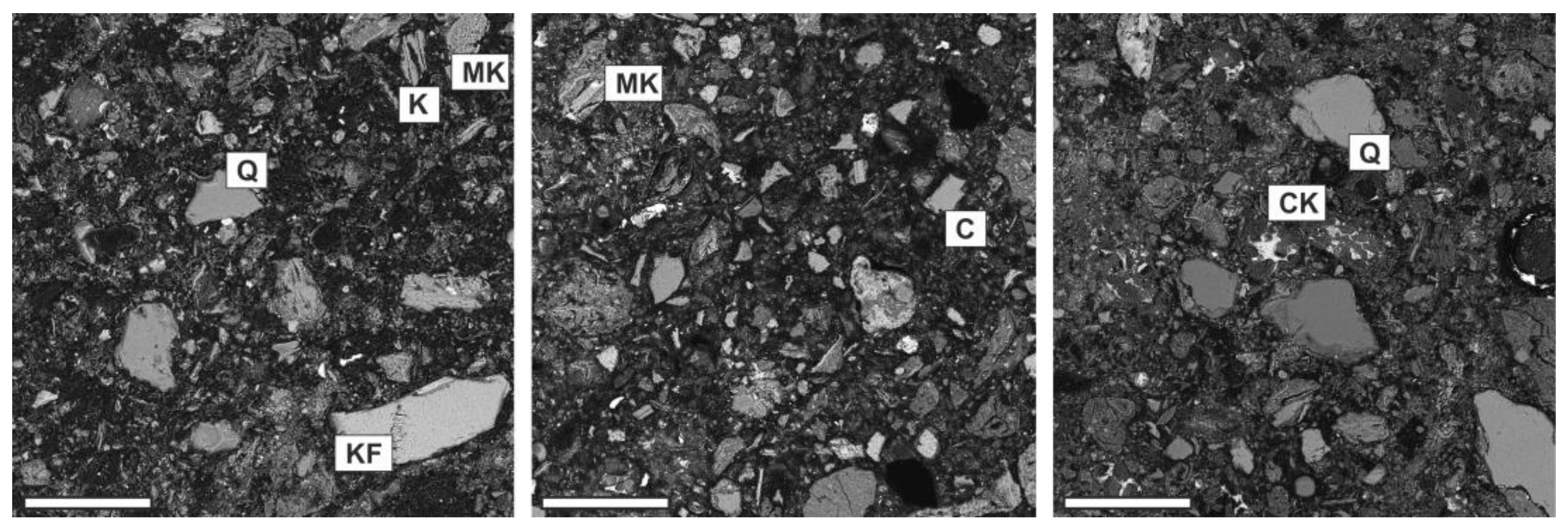
3.4. Microstructural and Microchemical Analyses of Hardened Pastes

SEM-BSE micrographs of the blended cement pastes containing KFs and CC at 28 days of curing are displayed in Figure 8. All microstructures consist of particles of unhydrated cement, clay minerals, quartz, calcite, and other unreacted phases in a relatively porous matrix. Inert mineral phases such as alkali feldspars can be observed in relatively large grains in sample S1′, which is the one having the largest amount of calcined clay fraction. Other than refractory phases such as feldspar, agglomerated metakaolinite grains can be observed. Crystals of calcite can be observed in sample S2′, which is the one that is more enriched in kunkur fines, confirming the slow reactivity of this phase. Sample S3′, which is the one having the largest fraction of OPC, presents several unhydrated clinker grains.
An example of the details of the matrix is displayed in Figure 9 for sample S1′. The matrix is composed of finely dispersed reaction products and small capillary pores. The EDS spectrum acquired in this location displays the presence of Ca, Si, Al, and S as major elements, compatible with the precipitation of C-(A)-S-H, portlandite, ettringite, and hemicarboaluminate.

4. Conclusions

This study preliminary assessed the possibility of utilizing kunkur fines, a waste material from the quarrying of caliche used in OPC clinker production, in sustainable binders, particularly for those applications in which the use of locally sourced raw materials is advantageous. These can include affordable housing and vernacular architecture.
The current results lead to the following conclusions:
  • A high level of clinker substitution with calcined clay and kunkur fines was studied. The highest compressive strength for the ternary blends was 30 MPa at day 28. This was a cement blend with a composition consisting of 40% clinker + 5% gypsum + 40% calcined clay + 15% kunkur fines.
  • Kunkur fines can possibly replace primary limestone in ternary blends, owing to their relatively high calcite content. The partial reactivity of this material is testified by the formation of hemicarboaluminate. However, the presence of kaolinite in the fines may hinder the overall performance, e.g., by increasing the water demand in the mix.
  • The presence of kunkur fines in the ternary blends leads to similar hydration products as those occurring in LC3 containing limestone.
The relevance of these findings to the broader field of sustainable construction is significant. The potential to reduce clinker content, which is an energy-intensive and CO2-emitting component in cement production, offers a more environmentally friendly approach. Moreover, the utilization of waste materials like kunkur fines for cement production aligns with the principles of circular economy and resource efficiency. However, the observed lower strength compared to OPC and standard LC3 requires that additional studies are performed to better understand the potential of kunkur fines in sustainable cement, and to elaborate strategies aimed at improving the engineering properties of such ternary blends, particularly when high OPC substitution levels are envisaged.
In particular: (a) investigating the mechanical performance at longer curing times and the durability of blends incorporating kunkur fines will likely provide a more comprehensive view of the potential of this secondary material in sustainable cement; (b) enhanced formulations in the presence of superplasticizers can reduce the water requirement in the presence of kunkur fines; and (c) dedicated life cycle assessment and life cycle cost studies can provide a more quantitative view of the possibility of reducing the environmental footprint and overall costs in the presence of kunkur fines. These insights have the potential to reshape the cement industry and contribute to the development of greener construction practices.

Author Contributions

Conceptualization, J.M.M. and V.K.M.; methodology, J.M.M. and L.V.; formal analysis, V.K.M. and L.V.; investigation, V.K.M.; resources, J.M.M. and L.V.; writing—original draft preparation, V.K.M.; writing—review and editing, L.V., J.M.M. and C.M.M.; visualization, V.K.M. and L.V.; supervision, J.M.M., C.M.M. and L.V.; project administration, J.M.M., C.M.M. and L.V.; funding acquisition, J.M.M. and L.V. All authors have read and agreed to the published version of the manuscript.

Funding

This research collaboration was carried out within the frame of the Erasmus+ KA107 Exchange Program of the European Commission, granted to the University of Padua and Meru University of Science and Technology. The support of the East African Portland Cement Company (EAPCC) is also acknowledged.

Institutional Review Board Statement

Not applicable.

Informed Consent Statement

Not applicable.

Data Availability Statement

The data presented in this study are available upon requests submitted to the corresponding author.

Conflicts of Interest

The authors declare no conflict of interest.

References

  1. UN Environment; Scrivener, K.; John, V.M.; Gartner, E.M. Eco-efficient Cements: Potential Economically Viable Solutions for a Low-CO2 Cement-based Materials Industry. Cem. Concr. Res. 2018, 114, 2–26. [Google Scholar] [CrossRef]
  2. Tennis, P.D.; Thomas, M.D.A.; Weiss, W.J. State-of-the-Art Report on Use of Limestone in Cements at Levels of up to 15%; PCA R&D SN3148; Portland Cement Association: Skokie, IL, USA, 2011. [Google Scholar]
  3. Scrivener, K.L. Options for the Future of Cement. Indian Concr. J. 2014, 88, 11–21. [Google Scholar]
  4. Machner, A.; Zajac, M.; Haha, M.B.; Kjellsen, K.O.; Geiker, M.R.; De Weerdt, K. Limitations of the Hydrotalcite Formation in Portland Composite Cement Pastes Containing Dolomite and Metakaolin. Cem. Concr. Res. 2018, 105, 1–17. [Google Scholar] [CrossRef]
  5. Oey, T.; Kumar, A.; Bullard, J.W.; Neithalath, N.; Sant, G. The Filler Effect: The Influence of Filler Content and Surface Area on Cementitious Reaction Rates. J. Am. Ceram. Soc. 2013, 96, 1978–1990. [Google Scholar] [CrossRef]
  6. Imbabi, M.S.; Carrigan, C.; McKenna, S. Trends and Developments in Green Cement and Concrete Technology. Int. J. Sustain. Built Environ. 2012, 1, 194–216. [Google Scholar] [CrossRef]
  7. Błaszczyński, T.; Król, M. Usage of Green Concrete Technology in Civil Engineering. Procedia Eng. 2015, 122, 296–301. [Google Scholar] [CrossRef]
  8. Habert, G.; Miller, S.A.; John, V.M.; Provis, J.L.; Favier, A.; Horvath, A.; Scrivener, K.L. Environmental Impacts and Decarbonization Strategies in the Cement and Concrete Industries. Nat. Rev. Earth Environ. 2020, 1, 559–573. [Google Scholar] [CrossRef]
  9. Scrivener, K.; Martirena, F.; Bishnoi, S.; Maity, S. Calcined Clay Limestone Cements (LC3). Cem. Concr. Res. 2018, 114, 49–56. [Google Scholar] [CrossRef]
  10. Dhandapani, Y.; Sakthivel, T.; Santhanam, M.; Gettu, R.; Pillai, R.G. Mechanical Properties and Durability Performance of Concretes with Limestone Calcined Clay Cement (LC3). Cem. Concr. Res. 2018, 107, 136–151. [Google Scholar] [CrossRef]
  11. Hanein, T.; Thienel, K.-C.; Zunino, F.; Marsh, A.; Maier, M.; Wang, B.; Canut, M.; Juenger, M.C.; Ben Haha, M.; Avet, F. Clay Calcination Technology: State-of-the-Art Review by the RILEM TC 282-CCL. Mater. Struct. 2022, 55, 3. [Google Scholar] [CrossRef]
  12. Medepalli, S.; Shah, V.; Bishnoi, S. Production of Lab Scale Limestone Calcined Clay Cements Using Low Grade Limestone. In Proceedings of the 7th International Conference on Sustainable Built Environment, Kandy, Sri Lanka, 16–18 December 2016. [Google Scholar]
  13. Zolfagharnasab, A.; Ramezanianpour, A.A.; Bahman-Zadeh, F. Investigating the Potential of Low-Grade Calcined Clays to Produce Durable LC3 Binders against Chloride Ions Attack. Constr. Build. Mater. 2021, 303, 124541. [Google Scholar] [CrossRef]
  14. Krishnan, S.; Gopala Rao, D.; Bishnoi, S. Why Low-Grade Calcined Clays Are the Ideal for the Production of Limestone Calcined Clay Cement (LC3). In Calcined Clays for Sustainable Concrete; Springer: Berlin/Heidelberg, Germany, 2020; pp. 125–130. [Google Scholar]
  15. Krishnan, S.; Emmanuel, A.C.; Shah, V.; Parashar, A.; Mishra, G.; Maity, S.; Bishnoi, S. Industrial Production of Limestone Calcined Clay Cement: Experience and Insights. Green Mater. 2019, 7, 15–27. [Google Scholar] [CrossRef]
  16. Emmanuel, A.C.; Haldar, P.; Maity, S.; Bishnoi, S. Second Pilot Production of Limestone Calcined Clay Cement in India: The Experience. Indian Concr. J. 2016, 90, 57–63. [Google Scholar]
  17. Danner, T.; Justnes, H.; Norden, G.; Østnor, T. Feasibility of Calcined Marl as an Alternative Pozzolanic Material. In Calcined Clays for Sustainable Concrete; Springer: Berlin/Heidelberg, Germany, 2015; pp. 67–73. [Google Scholar]
  18. Beuntner, N.; Thienel, K.C. Properties of Calcined Lias Delta Clay—Technological Effects, Physical Characteristics and Reactivity in Cement. In Calcined Clays for Sustainable Concrete; Springer: Berlin/Heidelberg, Germany, 2015; pp. 43–50. [Google Scholar]
  19. Bullerjahn, F.; Zajac, M.; Pekarkova, J.; Nied, D. Novel SCM Produced by the Co-Calcination of Aluminosilicates with Dolomite. Cem. Concr. Res. 2020, 134, 106083. [Google Scholar] [CrossRef]
  20. Marangu, J.M. Physico-Chemical Properties of Kenyan Made Calcined Clay-Limestone Cement (LC3). Case Stud. Constr. Mater. 2020, 12, e00333. [Google Scholar] [CrossRef]
  21. Marangu, J.M.; Latif, E.; Maddalena, R. Evaluation of the Reactivity of Selected Rice Husk Ash-Calcined Clay Mixtures for Sustainable Cement Production; Maddalena, R., Wright-Syed, M., Eds.; Cardiff University: Cardiff, Wales, 2021; pp. 81–84. [Google Scholar]
  22. Rahhal, V.; Pavlík, Z.; Trezza, M.; Castellano, C.; Tironi, A.; Kulovaná, T.; Pokorný, J.; Černý, R.; Irassar, E.F. Red Ceramic Wastes: A Calcined Clay Pozzolan. In Calcined Clays for Sustainable Concrete; Springer: Berlin/Heidelberg, Germany, 2015; pp. 179–187. [Google Scholar]
  23. Bentz, D.P.; Ferraris, C.F. Rheology and Setting of High Volume Fly Ash Mixtures. Cem. Concr. Compos. 2010, 32, 265–270. [Google Scholar] [CrossRef]
  24. Castellano, C.C.; Bonavetti, V.L.; Donza, H.A.; Irassar, E.F. The Effect of w/b and Temperature on the Hydration and Strength of Blastfurnace Slag Cements. Constr. Build. Mater. 2016, 111, 679–688. [Google Scholar] [CrossRef]
  25. Bonavetti, V.L.; Rahhal, V.F.; Irassar, E.F. Studies on the Carboaluminate Formation in Limestone Filler-Blended Cements. Cem. Concr. Res. 2001, 31, 853–859. [Google Scholar] [CrossRef]
  26. De Weerdt, K.; Kjellsen, K.O.; Sellevold, E.; Justnes, H. Synergy between Fly Ash and Limestone Powder in Ternary Cements. Cem. Concr. Compos. 2011, 33, 30–38. [Google Scholar] [CrossRef]
  27. Moesgaard, M.; Herfort, D.; Steenberg, M.; Kirkegaard, L.F.; Yue, Y. Physical Performances of Blended Cements Containing Calcium Aluminosilicate Glass Powder and Limestone. Cem. Concr. Res. 2011, 41, 359–364. [Google Scholar] [CrossRef]
  28. Cost, V.T.; Aci, F. Concrete Sustainability versus Constructability—Closing the Gap. In Proceedings of the 2011 International Concrete Sustainability Conference, Boston, MA, USA, 9–11 August 2011. [Google Scholar]
  29. Costa, E.B.C.; Cardoso, F.A.; John, V.M. Influence of High Contents of Limestone Fines on Rheological Behaviour and Bond Strength of Cement-Based Mortars. Constr. Build. Mater. 2017, 156, 1114–1126. [Google Scholar] [CrossRef]
  30. Sato, T.; Beaudoin, J.J. Effect of Nano-CaCO3 on Hydration of Cement Containing Supplementary Cementitious Materials. Adv. Cem. Res. 2011, 23, 33–43. [Google Scholar] [CrossRef]
  31. Ferrari, G.; Brocchi, A.; Castiglioni, F.; Bravo, A.; Moretti, E.; Salvioni, D.; Squinzi, M.; Artioli, G.; Dalconi, M.C.; Valentini, L. A New Multifunctional Additive for Blended Cements. Constr. Build. Mater. 2022, 354, 129086. [Google Scholar] [CrossRef]
  32. Nair, N.; Haneefa, K.M.; Santhanam, M.; Gettu, R. A Study on Fresh Properties of Limestone Calcined Clay Blended Cementitious Systems. Constr. Build. Mater. 2020, 254, 119326. [Google Scholar] [CrossRef]
  33. Sposito, R.; Beuntner, N.; Thienel, K.-C. Characteristics of Components in Calcined Clays and Their Influence on the Efficiency of Superplasticizers. Cem. Concr. Compos. 2020, 110, 103594. [Google Scholar] [CrossRef]
  34. Zhang, J.; Wang, Q.; Wang, Z. Optimizing Design of High Strength Cement Matrix with Supplementary Cementitious Materials. Constr. Build. Mater. 2016, 120, 123–136. [Google Scholar] [CrossRef]
  35. Fernández, Á.; Calvo, J.G.; Alonso, M.C. Ordinary Portland Cement Composition for the Optimization of the Synergies of Supplementary Cementitious Materials of Ternary Binders in Hydration Processes. Cem. Concr. Compos. 2018, 89, 238–250. [Google Scholar] [CrossRef]
  36. Eren, M. Caliche Formation and Features. Jeol. Mühendisliği Derg. 2006, 30, 1–8. [Google Scholar]
  37. Gareth, H. Mapping calcretes in Inhambane province, Mozambique, for use in road construction. In Bulletin of Engineering Geology and the Environment; Springer: Berlin/Heidelberg, Germany, 2015; pp. 405–426. Available online: https://link.springer.com/article/10.1007/s10064-014-0688-3 (accessed on 19 February 2023).
  38. Netterberg, F. Low-Cost Local Road Materials in Southern Africa. Geotech. Geol. Eng. 1994, 12, 35–42. [Google Scholar] [CrossRef]
  39. Reeves, C.C.; Suggs, J.D. Caliche of Central and Southern Llano Estacado, Texas. J. Sediment. Res. 1964, 34, 669–672. [Google Scholar] [CrossRef]
  40. Mutua, M.G. Investigation of Matisaa Gray Rock as a Potential Raw Material for the Manufacture of Cement. Master’s Thesis, Maasai Mara University, Narok, Kenya, 2020. [Google Scholar]
  41. Geoffrey, M.; Isaac, M.; Fredrick, O. Parametric Study of Matisaa Gray Rock as a Potential Clinker Material. Asian J. Adv. Res. Rep. 2020, 14, 22–29. [Google Scholar] [CrossRef]
  42. EN 196-1:2016; Methods of Testing Cement—Part 1: Determination of Strength. European Committee for Standardization: Brussels, Belgium, 2016.
  43. KS EAS 148-2:2017; Cement—Test Methods Part 2:Chemical Composition. Kenya Bureau of Standards: Nairobi, Kenya, 2017.
  44. Leardi, R. Experimental Design in Chemistry: A Tutorial. Anal. Chim. Acta 2009, 652, 161. [Google Scholar] [CrossRef]
  45. KS EAS 18-1:2017; Cement Part 1: Composition, Specification and Conformity Criteria for Common Cements. Kenya Bureau of Standards: Nairobi, Kenya, 2017.
  46. KS EAS 18-2:2017; Cement Part 2:Conformity Evaluation. Kenya Bureau of Standards: Nairobi, Kenya, 2017.
  47. Sui, H.; Hou, P.; Liu, Y.; Sagoe-Crentsil, K.; de Souza, F.B.; Duan, W. Limestone Calcined Clay Cement: Mechanical Properties, Crystallography, and Microstructure Development. J. Sustain. Cem.-Based Mater. 2022, 12, 427–440. [Google Scholar] [CrossRef]
  48. Snell, L. Caliche: Nature’s Natural Concrete. Concr. Int. 2016, 38, 70–71. [Google Scholar]
  49. Gameiro, A.; Silva, A.S.; Faria, P.; Grilo, J.; Branco, T.; Veiga, R.; Velosa, A. Physical and Chemical Assessment of Lime–Metakaolin Mortars: Influence of Binder: Aggregate Ratio. Cem. Concr. Compos. 2014, 45, 264–271. [Google Scholar] [CrossRef]
  50. Feng, Y.; Zhang, Q.; Chen, Q.; Wang, D.; Guo, H.; Liu, L.; Yang, Q. Hydration and Strength Development in Blended Cement with Ultrafine Granulated Copper Slag. PLoS ONE 2019, 14, e0215677. [Google Scholar] [CrossRef]
  51. Zunino, F.; Scrivener, K. The Reaction between Metakaolin and Limestone and Its Effect in Porosity Refinement and Mechanical Properties. Cem. Concr. Res. 2021, 140, 106307. [Google Scholar] [CrossRef]
Figure 1. Particle size distribution curves of raw clay (RC) and kunkur fines (KFs).
Sustainability 15 16453 g001
Figure 2. X-ray patterns of (top to bottom) kunkur fines, raw clay, and calcined clay. A, C, K, Mi, Mu, and Q represent albite, calcite, kaolinite, microcline, muscovite, and quartz, respectively.
Sustainability 15 16453 g002
Figure 3. Graphical representation of the mixture space with points representative of the seven experiments of the mixture design.
Sustainability 15 16453 g003
Figure 4. Isoresponse plots of the compressive strength at different curing days: (a) strength at day 2; (b) strength at day 7; and (c) strength at day 28.
Sustainability 15 16453 g004
Figure 5. Experimental results for the cement paste and mortar samples’ compressive strengths at various curing days.
Sustainability 15 16453 g005
Figure 6. XRD patterns for the cement samples S1′, S2′, and S3′ at 2, 7, and 28 days of curing. C, CH, C3S, C2S, C3A, Ett, Hc, K, Mi, P, and Q denote calcite, portlandite, alite, belite, aluminate, ettringite, hemicarboaluminate, kaolinite, microcline, and quartz, respectively.
Sustainability 15 16453 g006
Figure 7. Pozzolanic activity of the cement paste at curing age 2, 7, and 28 days.
Sustainability 15 16453 g007
Figure 8. SEM-BSE micrographs of samples S1′ (left), S2′ (center), and S3′ (right) at 28 days of hydration. Labels: C (calcite); CK (unhydrated clinker); K (kaolinite); KF (alkali feldspar); MK (metakaolinite); Q (quartz). The length of the scale bar corresponds to 100 μm.
Sustainability 15 16453 g008
Figure 9. SEM-BSE micrograph and associated EDS spectrum for the matrix of sample S1′. The length of the scalebar corresponds to 5 μm.
Sustainability 15 16453 g009
Table 1. XRF chemical composition (wt.%) of the starting materials.
Chemical Composition (w%)ClinkerCalcined ClayGypsumKunkur Fines
SiO221.359.37.252.3
Al2O36.329.51.39.6
Fe2O33.74.80.87.9
CaO62.20.729.514.5
SO31.5-40.40.2
MgO3.92.10.33.22
K2 O1.02.40.341.12
Na2O0.41.2--
Cl---0.01
L.O.I.0.8
Table 2. Mix composition (wt.%) for the prepared cement blends.
MixClinker (%)KFs (%)CC (%)GY (%)
S155.015.025.05.0
S240.015.040.05.0
S340.030.025.05.0
S440.022.532.55.0
S547.522.525.05.0
S647.515.032.55.0
S745.020.030.05.0
S895.0--5.0
Table 3. Mix composition (wt.%) for the prepared cement blends used for validation of the DoE model.
MixClinker (%)KFs (%)CC (%)GY (%)
S1′41.016.038.05.0
S2′42.026.027.05.0
S3′45.018.032.05.0
OPC95.0 5.0
Disclaimer/Publisher’s Note: The statements, opinions and data contained in all publications are solely those of the individual author(s) and contributor(s) and not of MDPI and/or the editor(s). MDPI and/or the editor(s) disclaim responsibility for any injury to people or property resulting from any ideas, methods, instructions or products referred to in the content.

