Hydrophilic Nature of Polytetrafluoroethylene through Modification with Perfluorosulfonic Acid-Based Polymers


Abstract
:1. Introduction
2. Materials
3. Methods
3.1. Preparation of Coating Solutions
3.2. Modification of PTFE
3.3. Instrumentation Methods
4. Results and Discussion
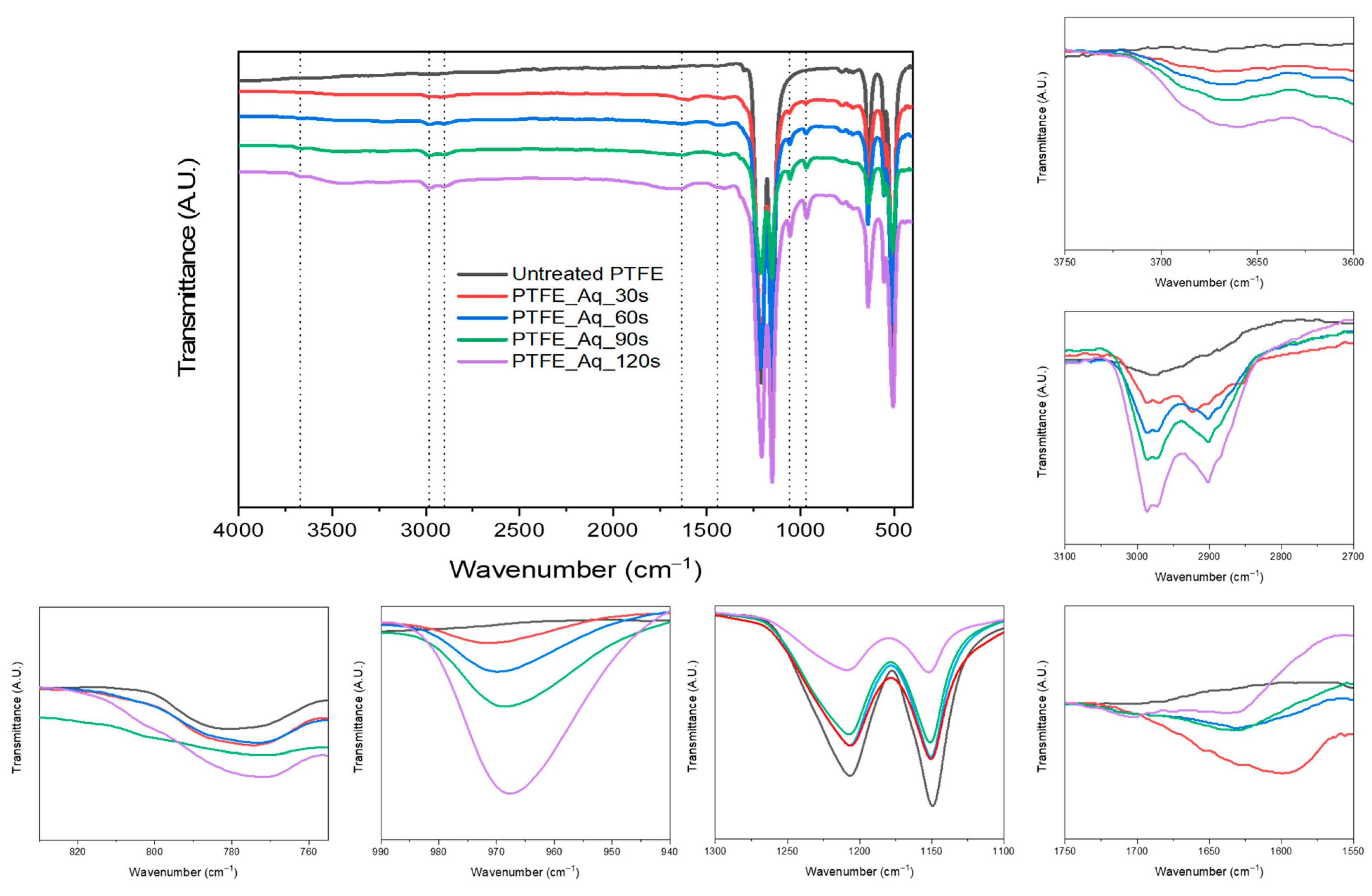
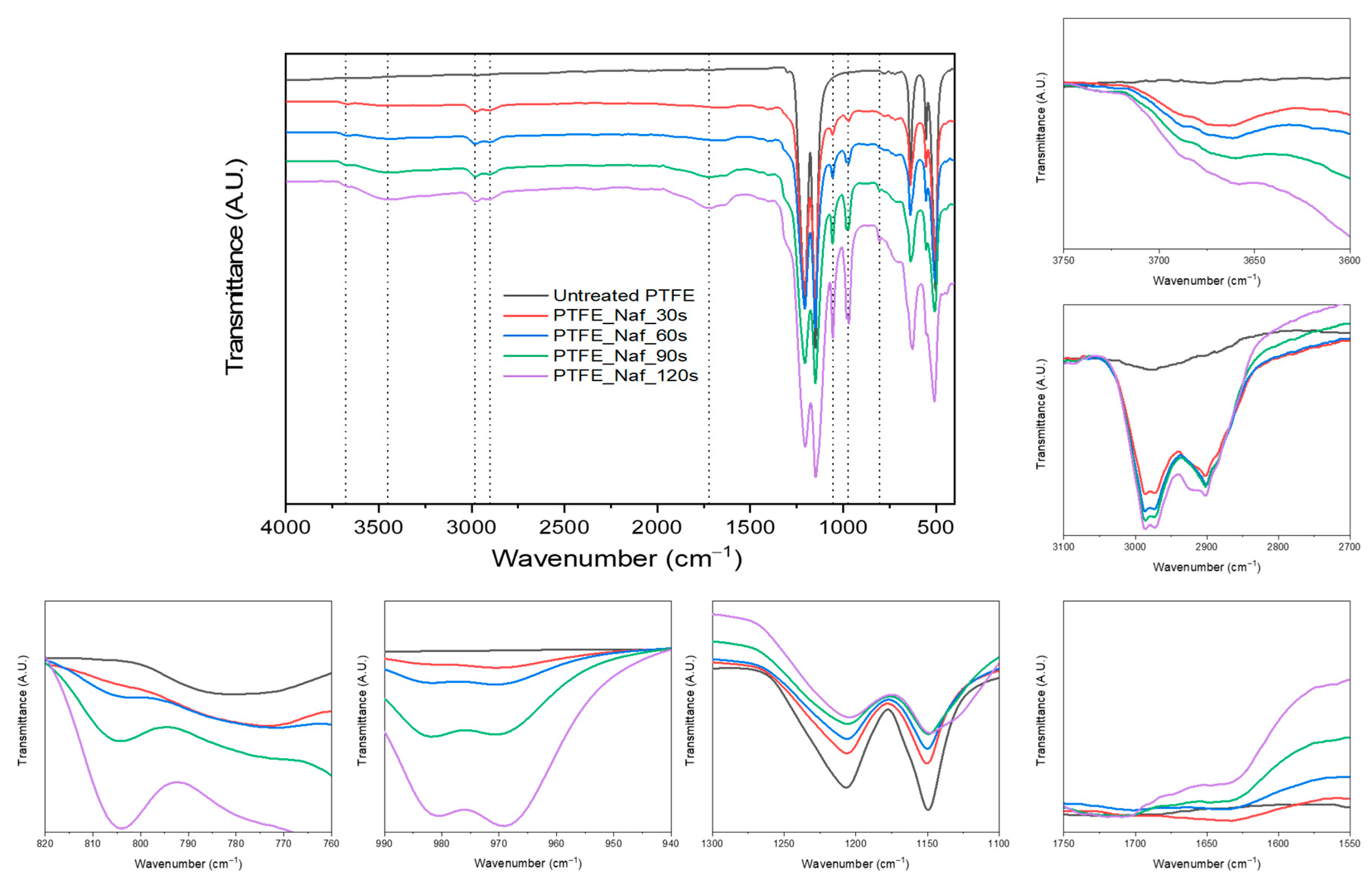
4.1. FT-IR Analysis
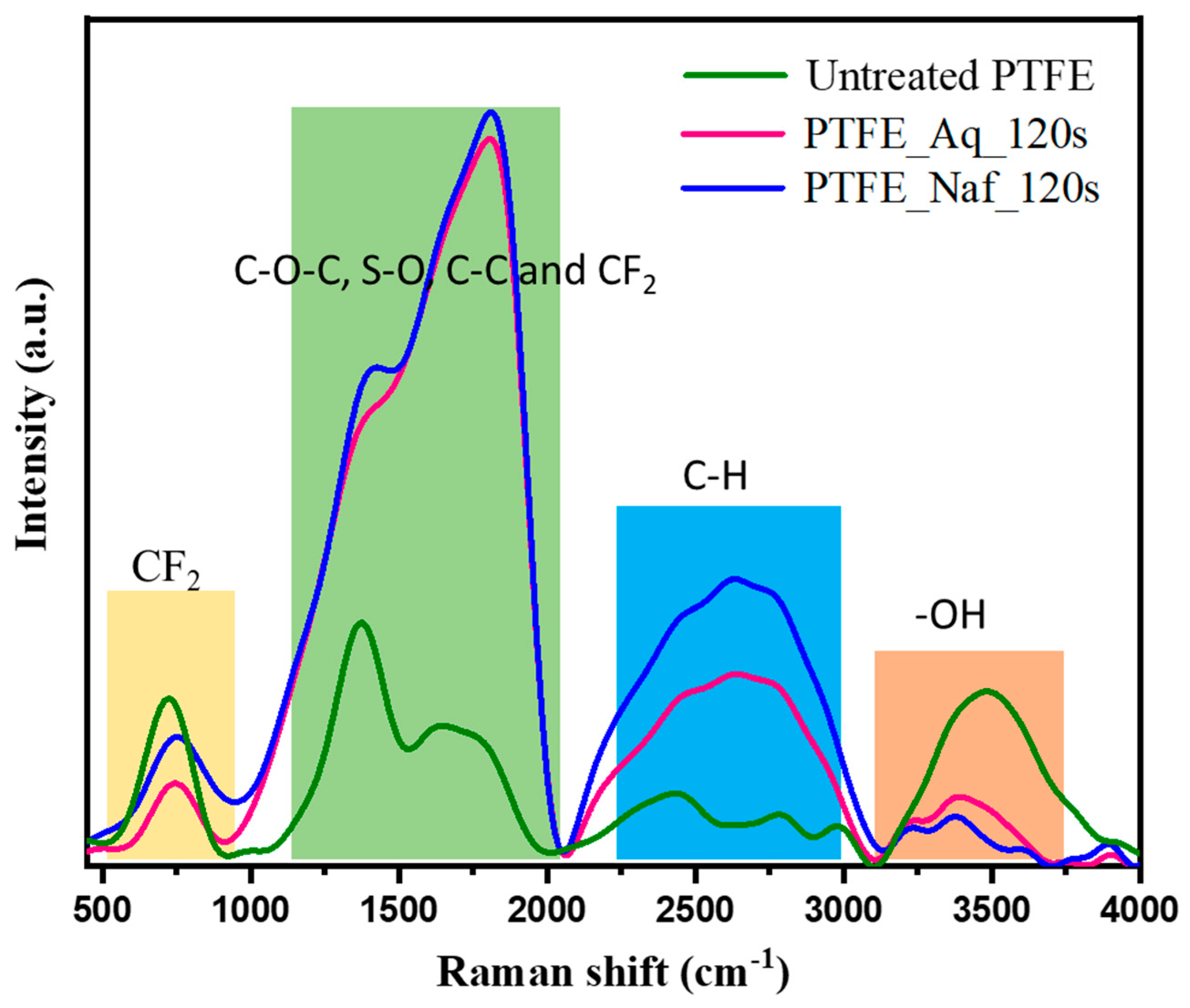
4.2. Raman Spectroscopy
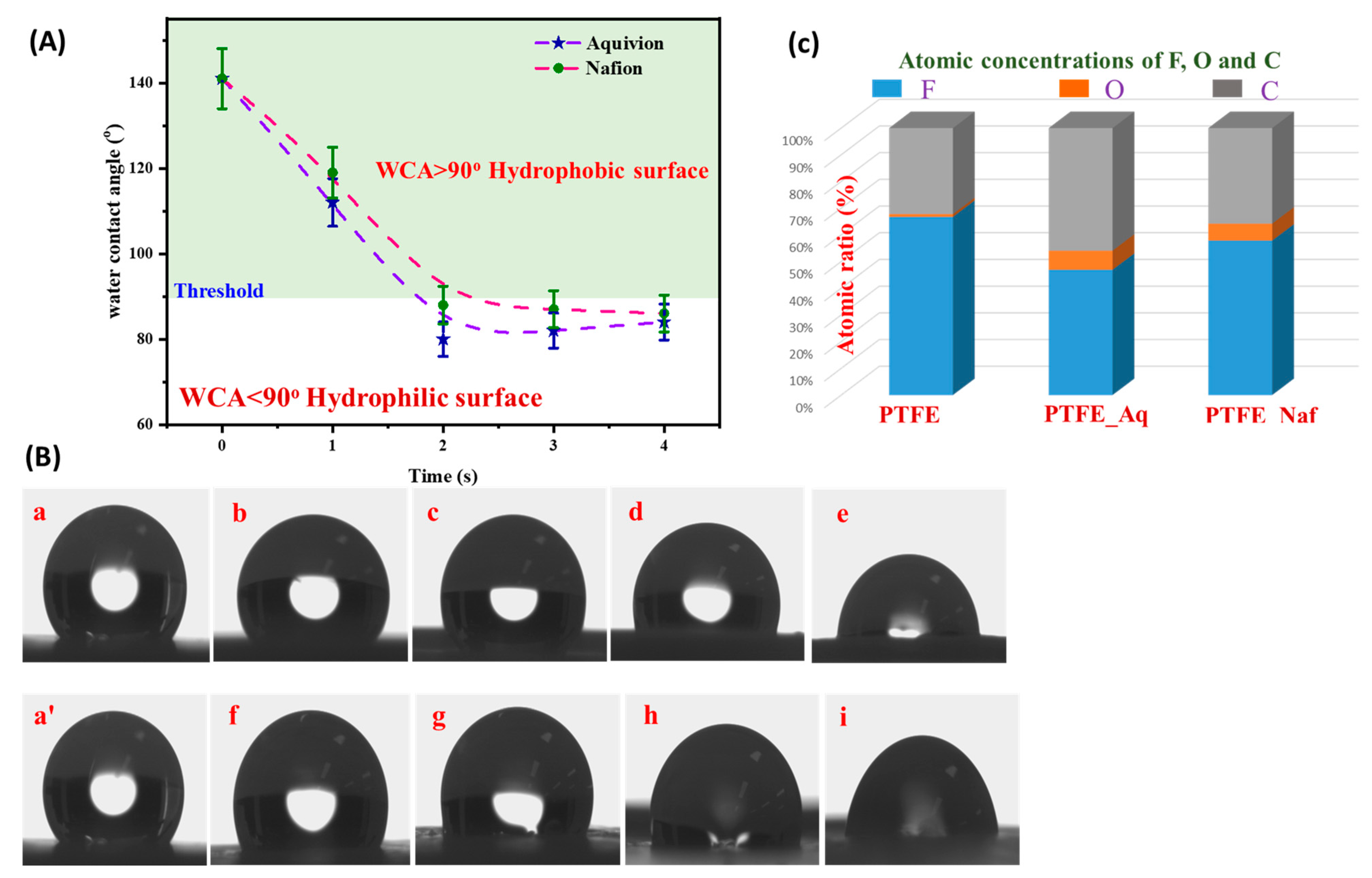
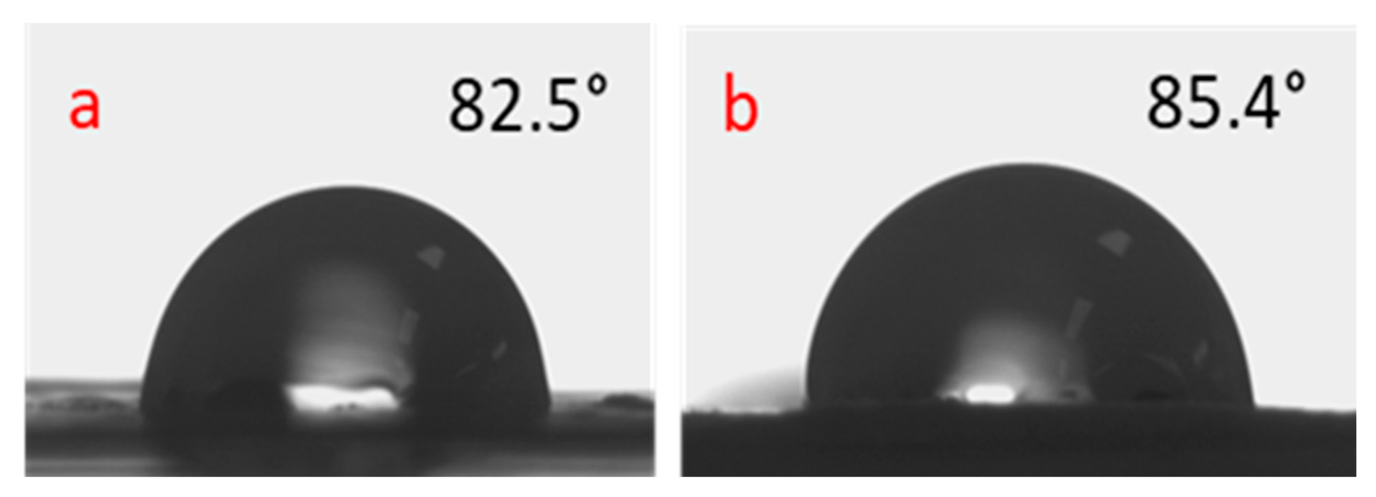
4.3. Water Contact Angle Analysis
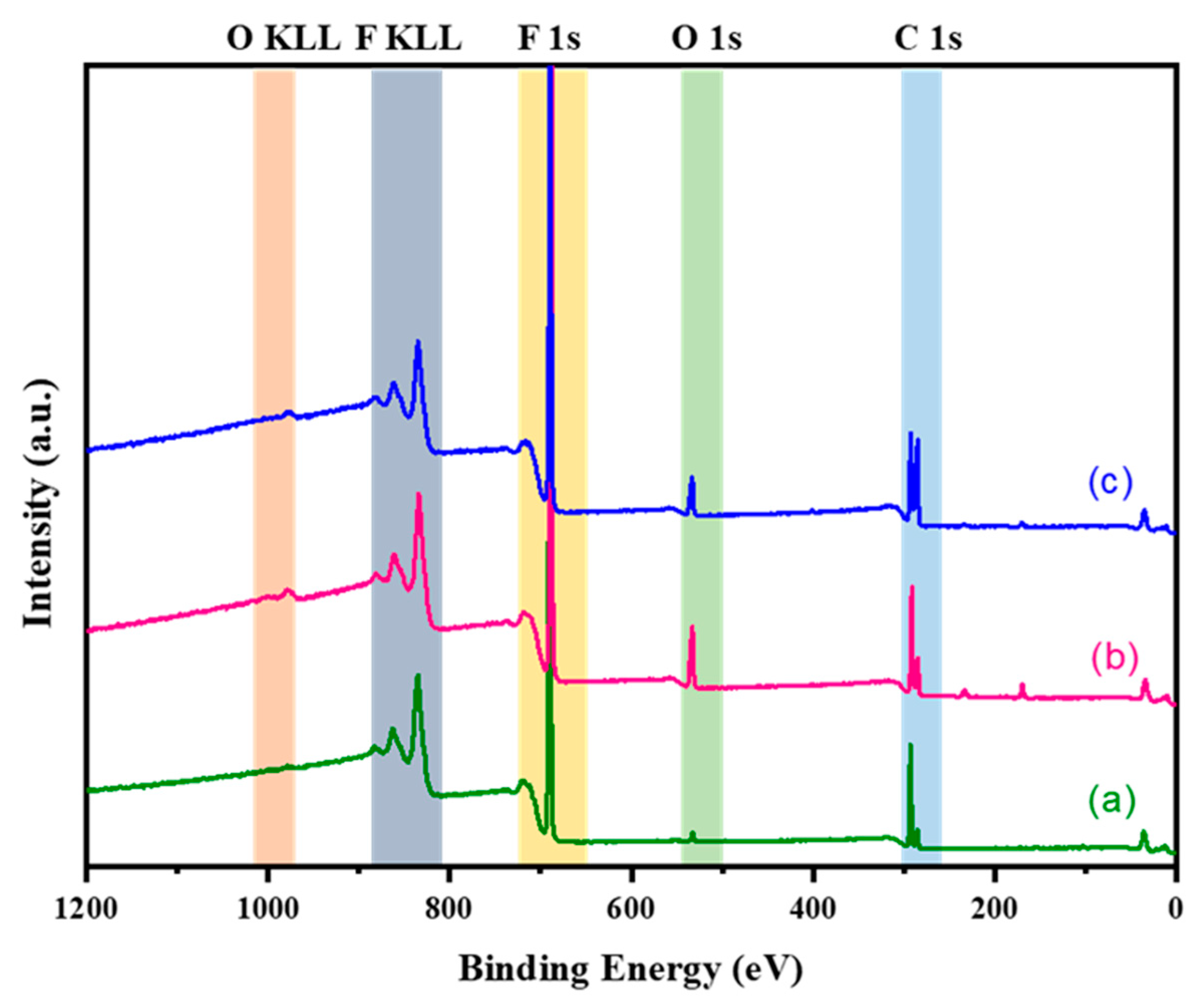
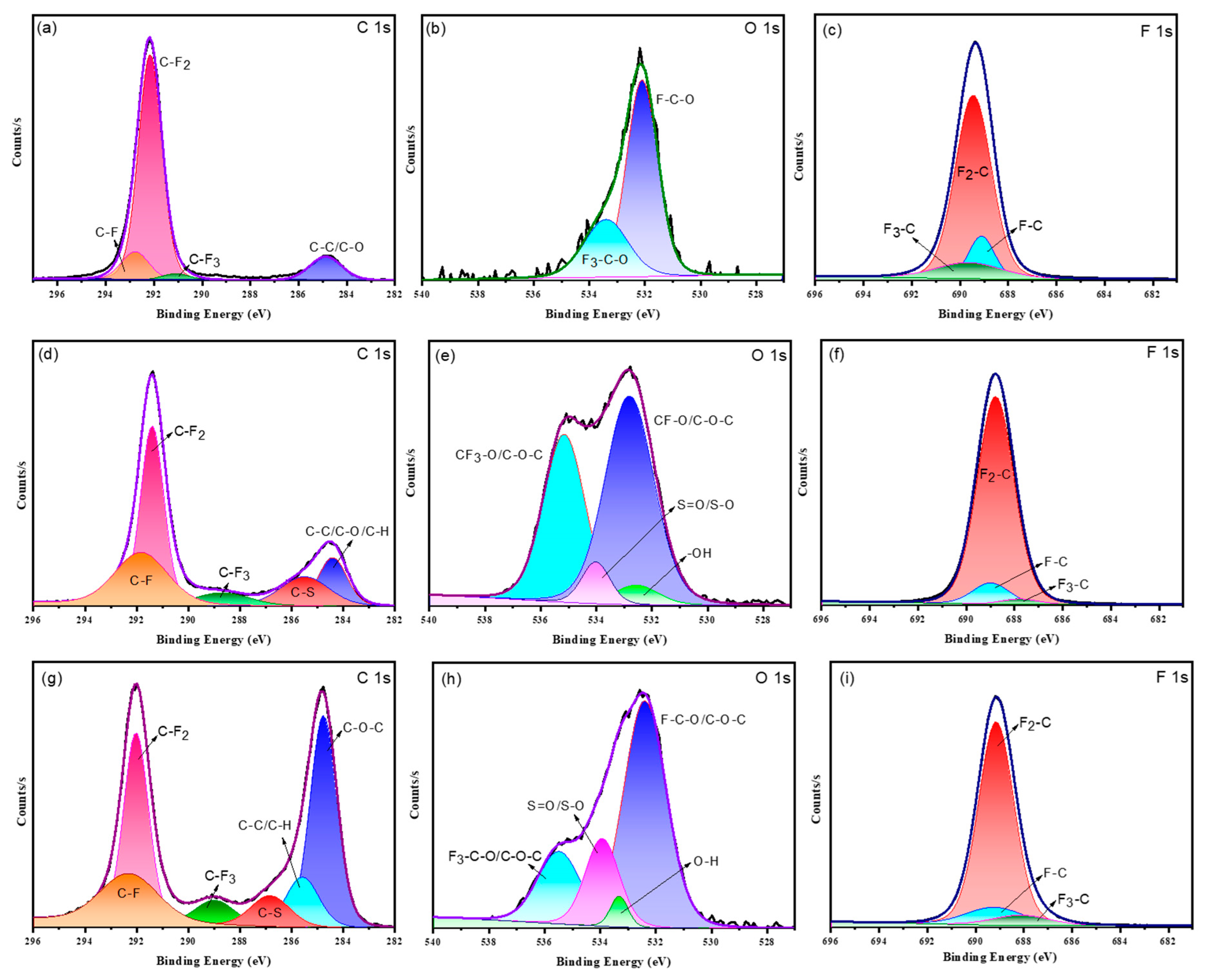
4.4. XPS Analysis
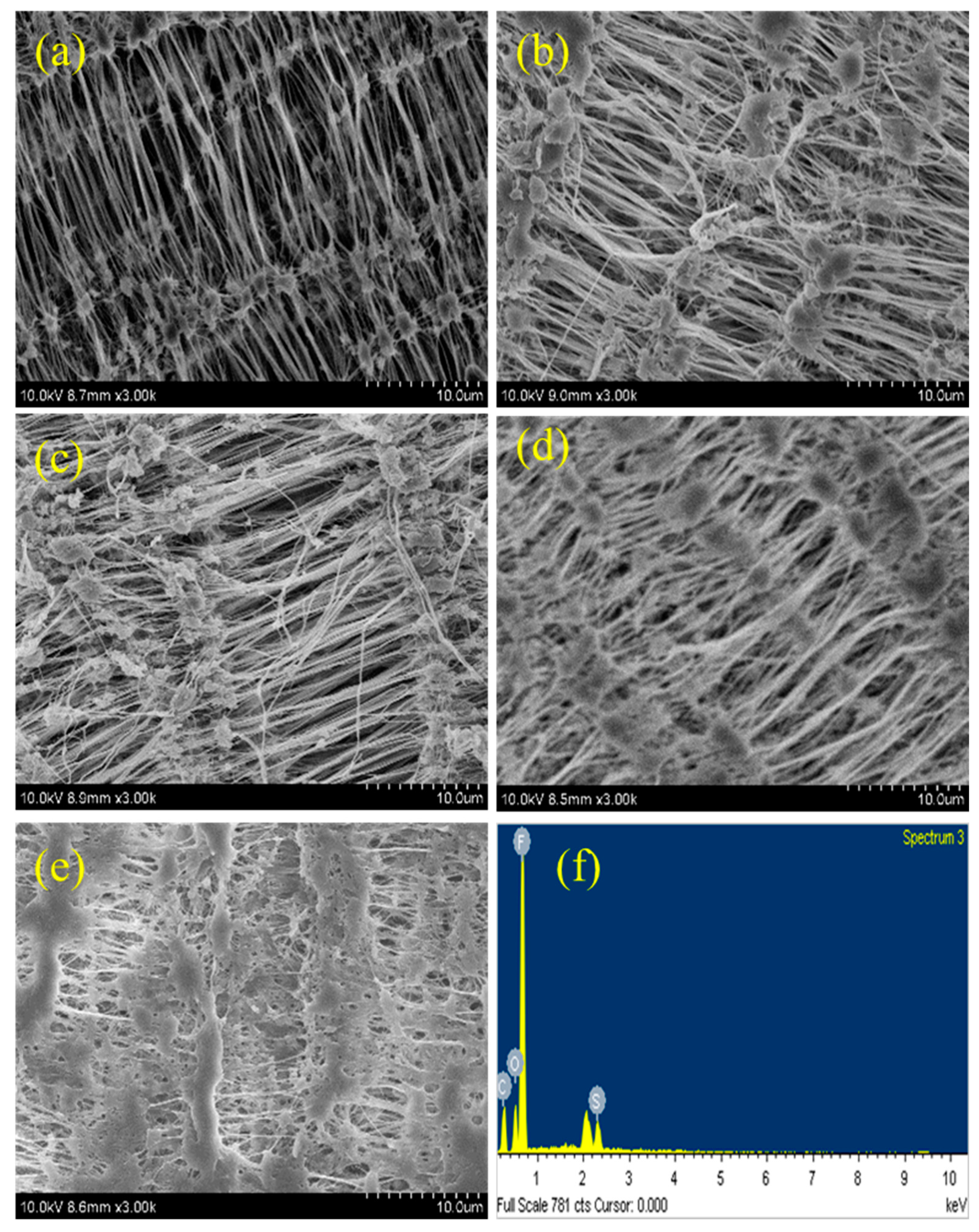
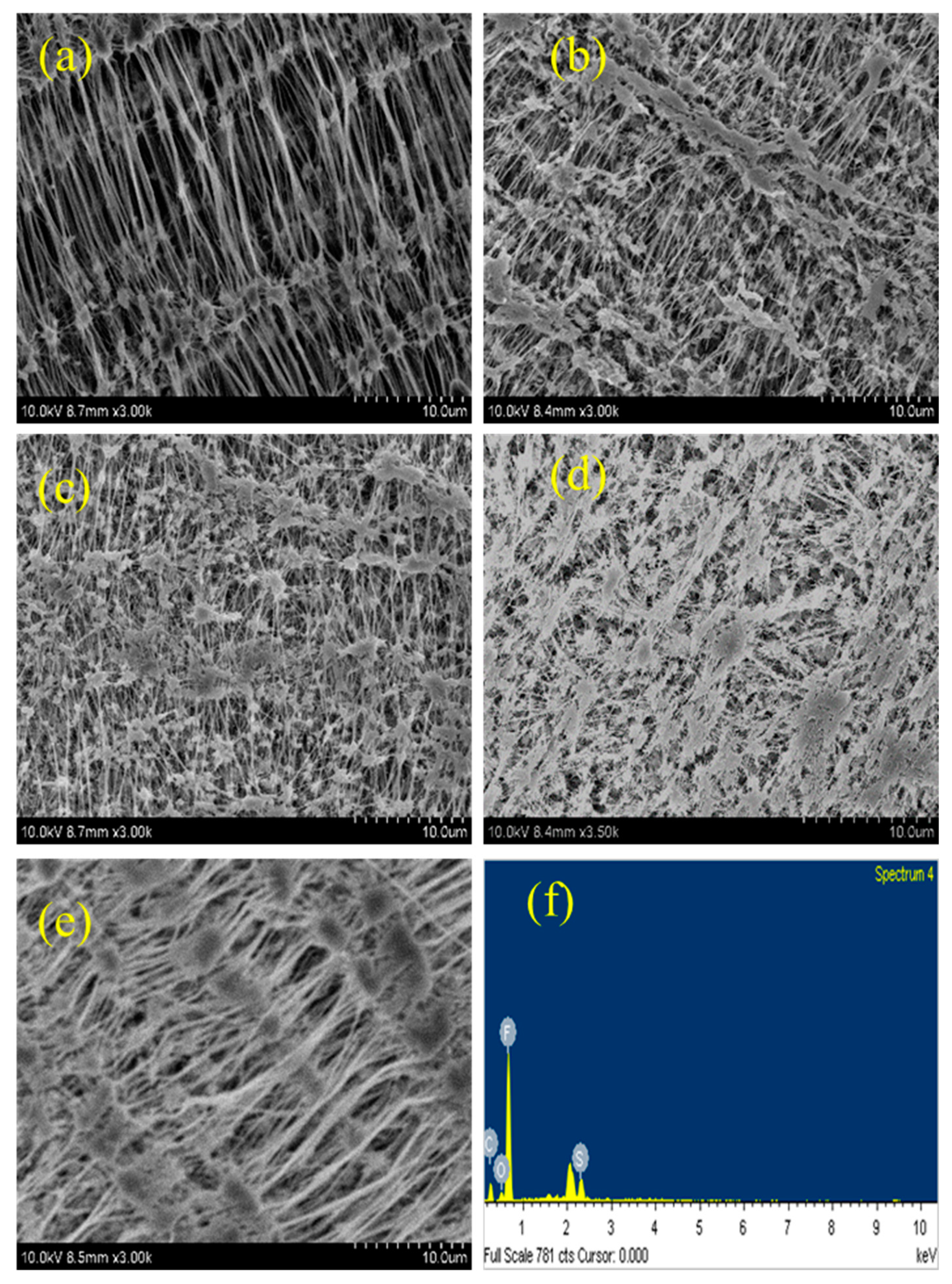
4.5. SEM Analysis
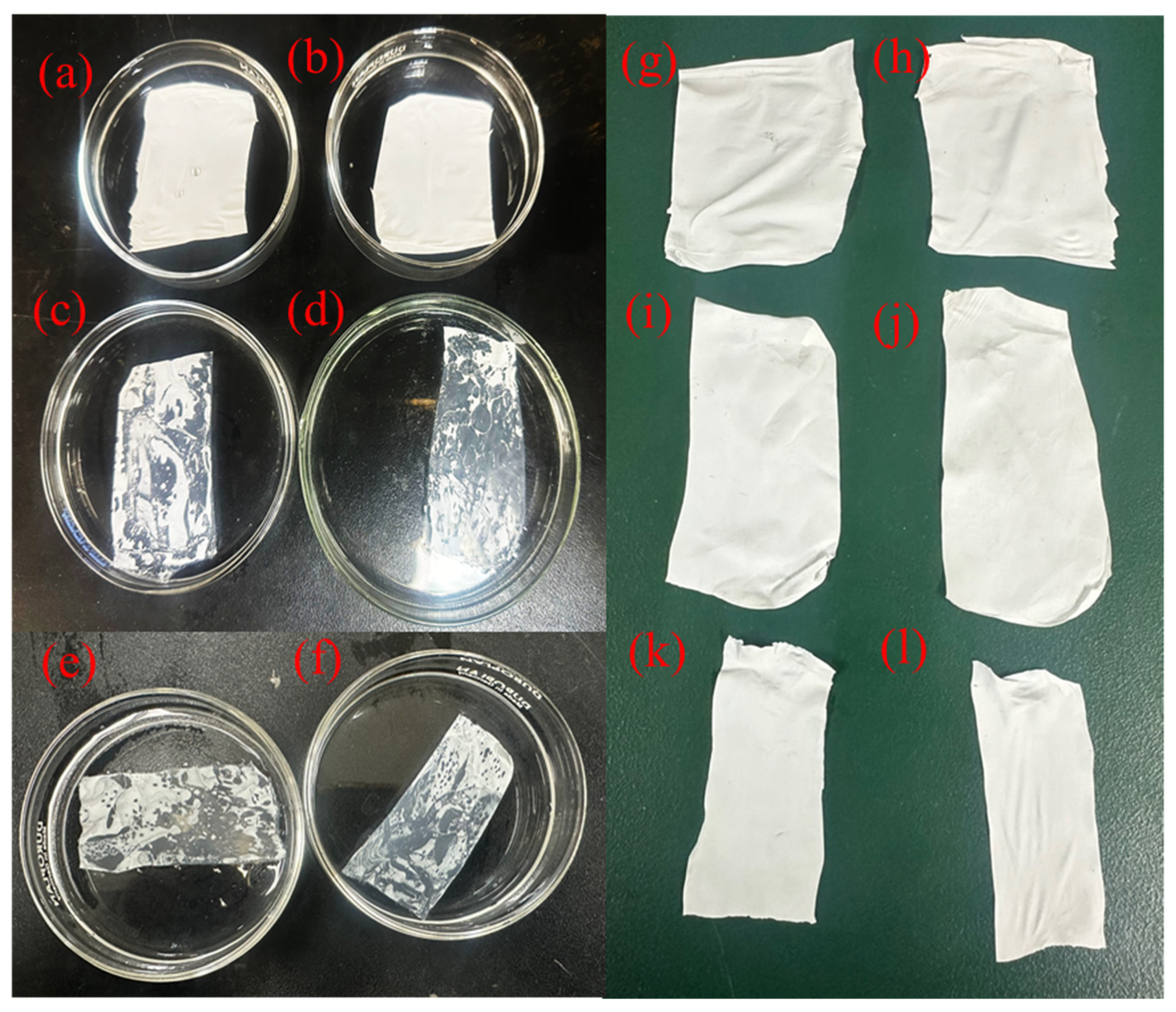
4.6. Stability of the Surface Treatment Process
4.7. Bulk Property of Modified PTFE
5. Summary and Conclusions
Author Contributions
Funding
Institutional Review Board Statement
Informed Consent Statement
Data Availability Statement
Conflicts of Interest
References
- Toma, M.; Loget, G.; Corn, R.M. Flexible Teflon Nanocone Array Surfaces with Tunable Superhydrophobicity for Self-Cleaning and Aqueous Droplet Patterning. ACS Appl. Mater. Interfaces 2014, 6, 11110–11117. [Google Scholar] [CrossRef]
- Sprick, R.S.; Cheetham, K.J.; Bai, Y.; Alves Fernandes, J.; Barnes, M.; Bradley, J.W.; Cooper, A.I. Polymer Photocatalysts with Plasma-Enhanced Activity. J. Mater. Chem. A 2020, 8, 7125–7129. [Google Scholar] [CrossRef]
- Vasile, C.; Baican, M.C.; Tibirna, C.M.; Tuchilus, C.; Debarnot, D.; Pslaru, E.; Poncin-Epaillard, F. Microwave Plasma Activation of a Polyvinylidene Fluoride Surface for Protein Immobilization. J. Phys. D. Appl. Phys. 2011, 44, 475303. [Google Scholar] [CrossRef]
- Surface Wet Chemical Treatment to Improve the Adhesion of Teflon. Available online: https://unitedadhesives.com/pdf/Teflon_Surface_Modification.pdf (accessed on 20 June 2021).
- Dowd, R.P.; Day, C.S.; Van Nguyen, T. Engineering the Ionic Polymer Phase Surface Properties of a PEM Fuel Cell Catalyst Layer. J. Electrochem. Soc. 2017, 164, F138–F146. [Google Scholar] [CrossRef]
- Yamada, Y.; Yamada, T.; Tasaka, S.; Inagaki, N. Surface Modification of Poly(Tetrafluoroethylene) by Remote Hydrogen Plasma. Macromolecules 1996, 29, 4331–4339. [Google Scholar] [CrossRef]
- Pegalajar-Jurado, A.; Joslin, J.M.; Hawker, M.J.; Reynolds, M.M.; Fisher, E.R. Creation of Hydrophilic Nitric Oxide Releasing Polymers via Plasma Surface Modification. ACS Appl. Mater. Interfaces 2014, 6, 12307–12320. [Google Scholar] [CrossRef] [PubMed]
- Zahreddine, C.; Pak, Y.S.; Xu, G. The Conductivity of the Novel PTFE Polymer Electrolytes. Solid State Ion. 1992, 58, 185–187. [Google Scholar] [CrossRef]
- López, C.D.; Cedeño-Mata, M.; Dominguez-Pumar, M.; Bermejo, S. Surface Modification of Polytetrafluoroethylene Thin Films by Non-Coherent UV Light and Water Treatment for Electrowetting Applications. Prog. Org. Coat. 2020, 149, 105593. [Google Scholar] [CrossRef]
- Liu, S.J.; Cui, S.P.; Qin, Z.P.; Fei, C.J.; Wang, Y.L.; Guo, H.X. A Novel Way to Modify PTFE Membrane into Hydrophilicity. Mater. Sci. Forum 2017, 898, 1892–1895. [Google Scholar] [CrossRef]
- Zdziennicka, A.; Jańczuk, B.; Wójcik, W. Wettability of Polytetrafluoroethylene by Aqueous Solutions of Two Anionic Surfactant Mixtures. J. Colloid Interface Sci. 2003, 268, 200–207. [Google Scholar] [CrossRef]
- Sharma, M.; Bharatiya, B.; Mehta, K.; Shukla, A.; Shah, D.O. Novel Strategy Involving Surfactant-Polymer Combinations for Enhanced Stability of Aqueous Teflon Dispersions. Langmuir 2014, 30, 7077–7084. [Google Scholar] [CrossRef] [PubMed]
- Park, S.Y.; Chung, J.W.; Kwak, S.Y. Regenerable Anti-Fouling Active PTFE Membrane with Thermo-Reversible “Peel-and-Stick” Hydrophilic Layer. J. Memb. Sci. 2015, 491, 1–9. [Google Scholar] [CrossRef]
- Ranji, H.; Babajanzadeh, B.; Sherizadeh, S. Detergents and Surfactants: A Brief Review. Open Access J. Sci. 2019, 3, 94–99. [Google Scholar] [CrossRef]
- Yesaswi, C.S.; Sreekanth, P.S.R. Evaluation of Dynamic Mechanical Properties of Teflon Fabric Reinforced Artificial Muscle Material. Mater. Today Proc. 2020, 27, 936–939. [Google Scholar] [CrossRef]
- Gatne, K.P.; Jog, M.A.; Manglik, R.M. Surfactant-Induced Modification of Low Weber Number Droplet Impact Dynamics. Langmuir 2009, 25, 8122–8130. [Google Scholar] [CrossRef]
- Wang, K.; Hou, D.; Wang, J.; Wang, Z.; Tian, B.; Liang, P. Hydrophilic Surface Coating on Hydrophobic PTFE Membrane for Robust Anti-Oil-Fouling Membrane Distillation. Appl. Surf. Sci. 2018, 450, 57–65. [Google Scholar] [CrossRef]
- Nawroth, J.F.; Neisser, C.; Erbe, A.; Jordan, R. Nanopatterned Polymer Brushes by Reactive Writing. Nanoscale 2016, 8, 7513–7522. [Google Scholar] [CrossRef]
- Bhullar, S.K.; Bedeloglu, A.; Jun, M.B.G. Characterization and Auxetic Effect of Polytetrafluoroethylene Tubular Structure. Int. J. Adv. Sci. Eng. 2014, 1, 8–13. [Google Scholar]
- Bonizzoni, S.; Stilli, P.; Lohmann-Richters, F.; Oldani, C.; Ferrara, C.; Papagni, A.; Beverina, L.; Mustarelli, P. Facile Chemical Modification of Aquivion® Membranes for Anionic Fuel Cells. ChemElectroChem 2021, 8, 2231–2237. [Google Scholar] [CrossRef]
- Dong, Y.; Gao, M.; Qiu, W.; Song, Z. The Influence of Humic and Fulvic Acids on Polytetrafluoroethylene-Adsorbed Arsenic: A Mechanistic Study. Environ. Sci. Pollut. Res. 2021, 28, 64503–64515. [Google Scholar] [CrossRef]
- Liu, C.; Cui, N.; Brown, N.M.D.; Meenan, B.J. Effects of DBD Plasma Operating Parameters on the Polymer Surface Modification. Surf. Coat. Technol. 2004, 185, 311–320. [Google Scholar] [CrossRef]
- Guruvenket, S.; Rao, G.M.; Komath, M.; Raichur, A.M. Plasma Surface Modification of Polystyrene and Polyethylene. Appl. Surf. Sci. 2004, 236, 278–284. [Google Scholar] [CrossRef]
- Bhowmik, S.; Jana, P.; Chaki, T.K.; Ray, S. Surface Modification of PP under Different Electrodes of DC Glow Discharge and Its Physicochemical Characteristics. Surf. Coat. Technol. 2004, 185, 81–91. [Google Scholar] [CrossRef]
- Der, O.; Bertola, V. An experimental investigation of oil-water flow in a serpentine channel. Int. J. Multiph. Flow 2020, 129, 103327. [Google Scholar] [CrossRef]
- Chen, S.; Bertoal, V. Drop impact on spherical soft surfaces. Phys. Fluids 2017, 29, 082106. [Google Scholar] [CrossRef]
- Ji, Z.; Zhao, Y.; Zhang, M.; Li, X.; Li, H. Surface Modification of ETFE Membrane and PTFE Membrane by Atmospheric DBD Plasma. Membranes 2022, 12, 510. [Google Scholar] [CrossRef] [PubMed]
- Shakila Parveen, A.; Thirukumaran, P.; Kim, S.-C. Rapid Transformation in Wetting Properties of PTFE Membrane Using Plasma Treatment. Polymers 2023, 15, 3874. [Google Scholar] [CrossRef]
- Schmälzlin, E.; Moralejo, B.; Rutowska, M.; Monreal-Ibero, A.; Sandin, C.; Tarcea, N.; Popp, J.; Roth, M.M. Raman Imaging with a Fiber-Coupled Multichannel Spectrograph. Sensors 2014, 14, 21968–21980. [Google Scholar] [CrossRef]
- Thomas, B.; Riko, M.; Matthias, B.; Simon, T.; Severin, V. Spatially Resolved Quantification of Ionomer Degradation in Fuel Cells by Confocal Raman Microscopy. J. Electrochem. Soc. 2019, 166, F3044–F3051. [Google Scholar] [CrossRef]
- Morra, M.; Occhiello, E.; Garbassi, F. Surface Characterization of Plasma-treated PTFE. Surf. Interface Anal. 1990, 16, 412–417. [Google Scholar] [CrossRef]
- Wilson, D.J.; Williams, R.L.; Pond, R.C. Plasma Modification of PTFE Surfaces—Part I: Surfaces Immediately Following Plasma Treatment. Surf. Interface Anal. 2001, 31, 385–396. [Google Scholar] [CrossRef]
- Jokinen, V.; Suvanto, P.; Franssila, S. Oxygen and Nitrogen Plasma Hydrophilization and Hydrophobic Recovery of Polymers. Biomicrofluidics 2012, 6, 016501. [Google Scholar] [CrossRef] [PubMed]
- D’Urso, B.; Simpson, J.T.; Kalyanaraman, M. Emergence of Superhydrophobic Behavior on Vertically Aligned Nanocone Arrays. Appl. Phys. Lett. 2007, 90, 044102. [Google Scholar] [CrossRef]
- Nosonovsky, M.; Bhushan, B. Biologically Inspired Surfaces: Broadening the Scope of Roughness. Adv. Funct. Mater. 2008, 18, 843–855. [Google Scholar] [CrossRef]
- Van Der Wal, P.; Steiner, U. Super-Hydrophobic Surfaces Made from Teflon. Soft Matter 2007, 3, 426–429. [Google Scholar] [CrossRef] [PubMed]
- Nilsson, M.A.; Daniello, R.J.; Rothstein, J.P. A Novel and Inexpensive Technique for Creating Superhydrophobic Surfaces Using Teflon and Sandpaper. J. Phys. D Appl. Phys. 2010, 43, 045301. [Google Scholar] [CrossRef]
- France, R.M.; Short, R.D. Plasma Treatment of Polymers Effects of Energy Transfer from an Argon Plasma on the Surface Chemistry of Poly(Styrene), Low Density Poly(Ethylene), Poly(Propylene) and Poly(Ethylene Terephthalate). J. Chem. Soc. Faraday Trans. 1997, 93, 3173–3178. [Google Scholar] [CrossRef]
- Becker, K.; Lupton, J.M.; Feldmann, J.; Nehls, B.S.; Galbrecht, F.; Gao, D.; Scherf, U. On-Chain Fluorenone Defect Emission from Single Polyfluorene Molecules in the Absence of Intermolecular Interactions. Adv. Funct. Mater. 2006, 16, 364–370. [Google Scholar] [CrossRef]
- Ranger, M.; Leclerc, M. Novel Base-Dopable Poly (2,7-Fluorenylene) Derivatives. Chem. Commun. 1997, 3, 1597–1598. [Google Scholar] [CrossRef]
- Park, Y.W.; Inagaki, N. A New Approach for Selective Surface Modification of Fluoropolymers by Remote Plasmas. J. Appl. Polym. Sci. 2004, 93, 1012–1020. [Google Scholar] [CrossRef]
- Ryan, M.E.; Badyal, J.P.S. Surface Texturing of PTFE Film Using Non-Equilibrium Plasmas. Macromolecules 1995, 28, 1377–1382. [Google Scholar] [CrossRef]
- Loh, F.C.; Lau, C.B.; Tan, K.L.; Kang, E.T. Surface Modification of Polyimide Films by Graft Copolymerization. J. Appl. Polym. Sci. 1995, 56, 1707–1713. [Google Scholar] [CrossRef]
- Inagaki, N.; Matsunaga, M. Preparation of Carboxylate Groups-Containing Thin Films by Plasma Polymerization. Polym. Bull. 1985, 13, 349–352. [Google Scholar] [CrossRef]
- Ye, Y.; Jiang, Y.; Yu, J.; Wu, Z.; Zeng, H. X-Ray Photoelectron Spectroscopy Characterization of the Interface between Ag Electrode and PVDF Film Treated by Electric Poling. J. Mater. Sci. Mater. Electron. 2006, 17, 1005–1009. [Google Scholar] [CrossRef]
- Vandencasteele, N.; Reniers, F. Surface Characterization of Plasma-Treated PTFE Surfaces: An OES, XPS and Contact Angle Study. Surf. Interface Anal. 2004, 36, 1027–1031. [Google Scholar] [CrossRef]
- Akkan, C.K.; Hammadeh, M.; Brück, S.; Park, H.W.; Veith, M.; Abdul-Khaliq, H.; Aktas, C. Plasma and Short Pulse Laser Treatment of Medical Grade PEEK Surfaces for Controlled Wetting. Mater. Lett. 2013, 109, 261–264. [Google Scholar] [CrossRef]
- Médard, N.; Soutif, J.C.; Poncin-Epaillard, F. Characterization of CO2 Plasma-Treated Polyethylene Surface Bearing Carboxylic Groups. Surf. Coat. Technol. 2002, 160, 197–205. [Google Scholar] [CrossRef]
- Yin, Y.; Bax, D.; McKenzie, D.R.; Bilek, M.M.M. Protein Immobilization Capacity and Covalent Binding Coverage of Pulsed Plasma Polymer Surfaces. Appl. Surf. Sci. 2010, 256, 4984–4989. [Google Scholar] [CrossRef]
- Park, S.J.; Kim, J.S. Influence of Plasma Treatment on Microstructures and Acid-Base Surface Energetics of Nanostructured Carbon Blacks: N2 Plasma Environment. J. Colloid Interface Sci. 2001, 244, 336–341. [Google Scholar] [CrossRef]
- Bryjak, M.; Gancarz, I.; Poz, G. Surface Evaluation of Plasma-Modified Polysulfone (Udel P-1700) Films. Langmuir 1999, 15, 6400–6404. [Google Scholar] [CrossRef]

Disclaimer/Publisher’s Note: The statements, opinions and data contained in all publications are solely those of the individual author(s) and contributor(s) and not of MDPI and/or the editor(s). MDPI and/or the editor(s) disclaim responsibility for any injury to people or property resulting from any ideas, methods, instructions or products referred to in the content. |
© 2023 by the authors. Licensee MDPI, Basel, Switzerland. This article is an open access article distributed under the terms and conditions of the Creative Commons Attribution (CC BY) license (https://creativecommons.org/licenses/by/4.0/).
Share and Cite
Asrafali, S.P.; Periyasamy, T.; Kim, S.-C. Hydrophilic Nature of Polytetrafluoroethylene through Modification with Perfluorosulfonic Acid-Based Polymers. Sustainability 2023, 15, 16479. https://doi.org/10.3390/su152316479
Asrafali SP, Periyasamy T, Kim S-C. Hydrophilic Nature of Polytetrafluoroethylene through Modification with Perfluorosulfonic Acid-Based Polymers. Sustainability. 2023; 15(23):16479. https://doi.org/10.3390/su152316479
Chicago/Turabian StyleAsrafali, Shakila Parveen, Thirukumaran Periyasamy, and Seong-Cheol Kim. 2023. "Hydrophilic Nature of Polytetrafluoroethylene through Modification with Perfluorosulfonic Acid-Based Polymers" Sustainability 15, no. 23: 16479. https://doi.org/10.3390/su152316479
APA StyleAsrafali, S. P., Periyasamy, T., & Kim, S.-C. (2023). Hydrophilic Nature of Polytetrafluoroethylene through Modification with Perfluorosulfonic Acid-Based Polymers. Sustainability, 15(23), 16479. https://doi.org/10.3390/su152316479