Article

Recycling Waste Plastics into Plastic-Bonded Sand Interlocking Blocks for Wall Construction in Developing Countries

by
Alexander Kumi-Larbi Jnr
1,*,
Latifatu Mohammed
2,
Trinity Ama Tagbor
2,
Samuel Kofi Tulashie
3 and
Christopher Cheeseman
1
1
UKCRIC Advanced Infrastructure Materials Laboratory, Department of Civil and Environmental Engineering, Imperial College London, London SW7 2BU, UK
2
Council for Scientific and Industrial Research, Institute of Industrial Research, Accra P.O. Box LG 587, Ghana
3
Industrial Chemistry Section, Department of Chemistry, School of Physical Sciences, College of Agriculture and Natural Sciences, University of Cape Coast, Cape Coast PMB TF0494, Ghana
*
Author to whom correspondence should be addressed.
Sustainability 2023, 15(24), 16602; https://doi.org/10.3390/su152416602
Submission received: 28 October 2023 / Revised: 24 November 2023 / Accepted: 30 November 2023 / Published: 6 December 2023
(This article belongs to the Section Waste and Recycling)

Abstract

:
This paper reports on using waste polyethylene to form plastic-bonded sand interlocking blocks for wall construction. The production process, mechanical properties, and failure mechanisms of three different interlocking block wall systems are reported. Plastic-bonded composite blocks were formed by mixing sand into waste polyethylene in a high-temperature extruder. The blocks formed had densities between 1.5 and 1.6 g cm−3 and compressive strengths of approximately 15.0 MPa. This is significantly higher than the conventional sandcrete wall blocks that are widely used in developing countries. The blocks were used to construct walls with dimensions of 1.0 m × 1.0 m × 0.15 m, and these were subjected to in-plane compressive loads. The compressive strengths of the walls ranged from 4.2 to 5.7 MPa. Variations in the block composition did not affect the failure mechanism, but the extent of the block damage after failure varied significantly. The potential for using waste plastics to form interlocking construction blocks for use in low-cost construction is discussed.

1. Introduction

Although the adverse impacts of poor waste management in developing countries (DCs) on public health are well known [1], government investment in sustainable waste management systems remains inadequate [2]. Approximately 16 wt.% of global municipal solid waste is plastics, and due to inadequate plastic recycling, 15 to 40 wt.% of the plastic waste is disposed into water bodies in DCs [3,4]. The poorly managed plastics can block drains and waterways, causing floods and disease. In 2015, such floods claimed at least 150 lives in Accra, Ghana [5]. The blocked drains also breed rodents, mosquitoes, and other disease-causing vectors. Accra recorded approximately 293,000 and 12,000 cases of malaria and diarrhoea in 2005 [6]. It is estimated that approximately 80% of ocean plastics originate from waste dumped indiscriminately on land [7]. This adversely influences marine life, as macroplastics can entangle or choke aquatic animals [8]. Plastics in the oceans also disintegrate into microplastics over time and these can be ingested by aquatic animals, leading to the bioaccumulation of plastics in the food chain [4,9,10].
Ghana has recently invested in sophisticated material recovery facilities to improve plastic recycling and avoid contributing to ocean plastics. The recovered waste plastics are processed into bins, packaging bags, and pellets for exportation. However, inadequate waste management financing threatens the sustainability of such recycling infrastructure. Therefore, developing low-cost technologies that use single-use plastics to produce products with longer lifespans, such as construction materials, is highly desirable.
Several research groups have investigated using waste plastics as aggregate or as reinforcement in lightweight concrete products [11,12]. PP, PE, PET, and PS can be used as alternative aggregates in concrete [13,14,15]. PA inclusion reduces concretes’ bulk densities by increasing the air voids [11]; however, the porosity increase reduces the compressive, flexural, and splitting tensile strengths of the concrete mixtures [16].
Bitumen modified with rubber, PP, and PE additives has improved the durability, rutting resistance, and viscoelasticity of polymer-modified pavements [17,18,19,20,21,22]. PE water sachets increased the viscosity and fatigue resistance and decreased the thermal stress cracking of polymer-modified asphalt The flow of modified asphalt is indirectly proportional to the PE content [23,24]. Polymer-coated aggregates can reduce the bitumen requirements for asphalt production by 10% [25]. PCA addition increased the load resistance capacity of flexible pavements and offered better stripping properties, with higher Marshall stability values between 18 and 20 kN. The compressive strength of PCA is directly proportional to the polymer coating volume due to the superior adhesive properties of molten plastics [25]. PCAs have improved mechanical properties including toughness, impact resistance, and strength because of their reduced porosity.
Polyethylene terephthalate (PET) fibres can strengthen soils [26]. PET containers filled with compacted soil have been used in walls and slabs [27]. Food wrapper-filled plastic bottles have been used to produce eco-bricks [28].
Research investigating the use of waste plastics as binders in composites is limited. Literature reports suggest the compressive strengths of plastic-bonded aggregate composites range from 2.1 to 31.4 MPa depending on the constituent properties. The optimum plastic-to-sand proportions for compressive strength are between 65 and 86% of the FA content. A higher aggregate content reduces the binder thickness to properly encapsulate the aggregate grains [29,30,31,32,33]. PP-bonded sand attains three times the load resistance of asphalt concrete. Typically, plastic-bonded aggregate composites offer a higher flexural to compressive strength ratio than conventional concrete [33].
Access to affordable housing in DCs is often difficult because of the complexities and costs associated with conventional building construction. Ghana has a deficit of at least 1.8 million houses [34]. The use of interlocking blocks simplifies construction and reduces investment costs. The large-scale production of interlocking blocks made from waste plastics would directly support efforts to achieve the sustainable development goals in DCs as this would create jobs in the plastic recycling value chain and the construction industry to help alleviate poverty. Walls constructed from waste plastics would drive environmental sustainability because they consume large quantities of waste plastics that are currently dumped indiscriminately into the environment. Using waste plastics as the binder in building blocks is also expected to minimise the carbon footprint of construction.
The aim of this research is to investigate the mechanical performance of plastic-bonded sand interlocking blocks and wall panels to assess their technical suitability for wall construction. This paper is the first to report on the mechanical performance and failure mechanisms of these types of walls.

2. Materials and Methods
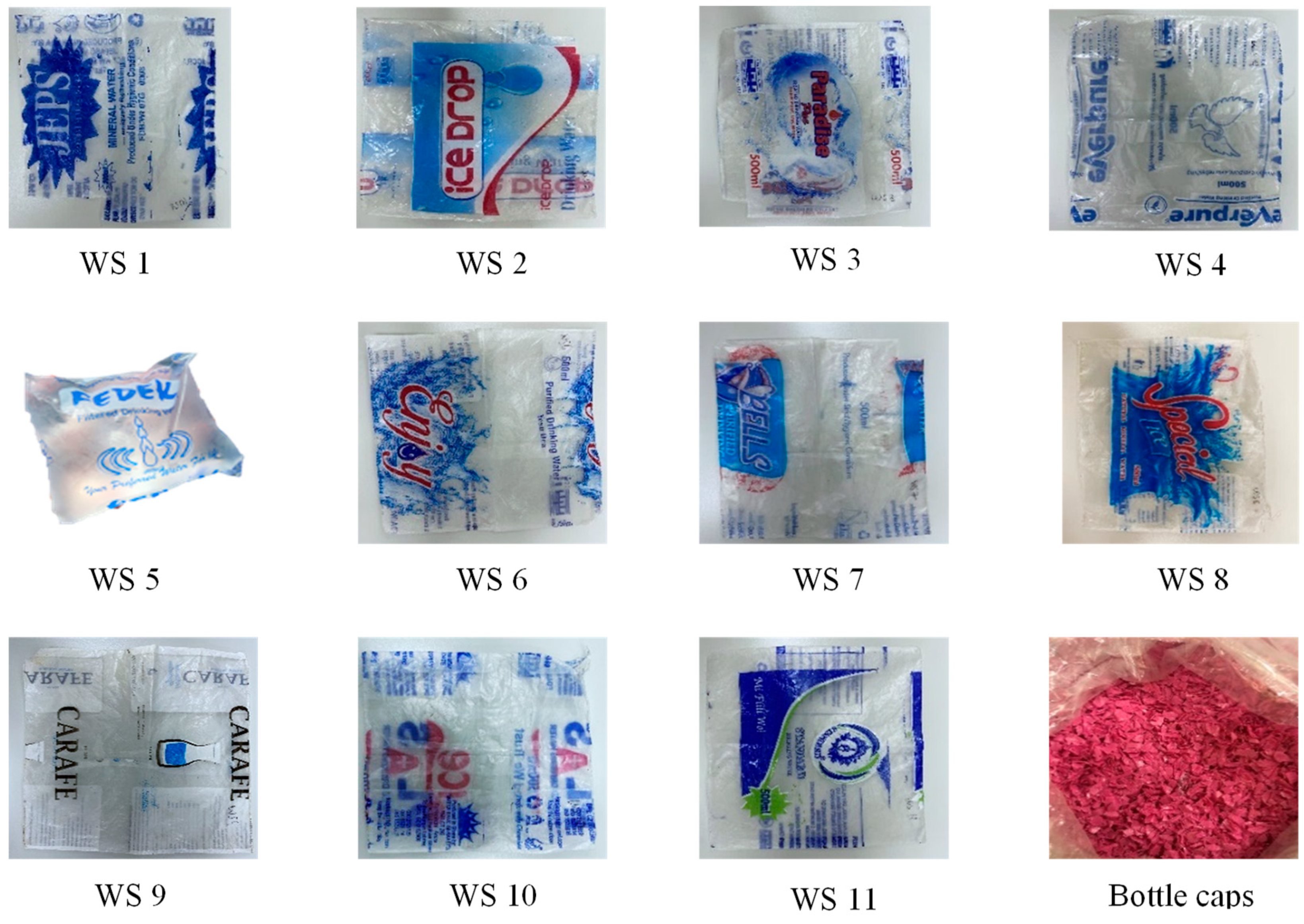
2.1. Materials

Water sachets and plastic bottle caps were used as the plastic binder to produce the interlocking block samples. The plastic waste samples were obtained from informal plastic recyclers in the Greater Accra Metropolitan Area, Ghana. These recyclers sort the plastics from the municipal solid waste (MSW) collected from households. Figure 1 shows 11 samples representing the complete variation of water sachets recovered from MSW. These samples were characterised to ascertain the different compositions of PE used in producing the water sachets in the study area. The bottle caps were identified as HDPE from their resin identification code. The plastic waste types were selected because they are ubiquitous and the most problematic in DCs.
The plastics were characterised using Fourier Transform Infrared Spectroscopy (FTIR, ThermoFisher Scientific, Paisley, UK, Nicolet iS50 FTIR spectrometer with the Michelson interferometer configuration). This showed the polymer composition and crystallinity of water sachets and bottle cap samples. Each test was conducted at a nominal resolution of 4 cm−1 for 30 cycles, and sample spectra were compared to reference spectra of pure PE. Plastic waste that is dumped in the environment breaks down under prolonged UV exposure. Hence, the carbonyl indices of the water bottles were used to assess the extent of degradation before producing the interlocking block samples [35,36]. The carbonyl indices were calculated from the ratio of the area under the absorbance peaks of the carbonyl compounds to the C–H compounds. The absorbance peaks observed within 1680–1600 cm−1 and 1480–1430 cm−1 correspond to the carbonyl and C–H compounds of PE, respectively [37].
DSC analysis of the waste plastics was performed following ASTM D3418-15 [38] (Netzsch STA 449, Jupiter F5 heat flux DSC) using N2 at a gas flow rate of 50 mL min−1 and a heating and cooling rate of 10 K min−1. The DSC shows the temperatures at which the plastics undergo chemical and physical transitions during thermal processing [38,39]. The analysis used 7 ± 1 mg of sample, and this was pressed into the crucible to ensure efficient heat transfer. The plastic samples were subjected to a heat–cool–heat temperature program (from 30 °C to 250 °C to 30 °C to 600 °C). The first heating cycle erased the thermal history of the sample, and the second heating cycle provided the sample identification data. The sample crystallinity was computed from the sample’s heat of fusion normalised with the heat of fusion of 100% crystalline PE.
River sand was used as the filler aggregate. River sand is the most preferred construction aggregate due to its smoothly rounded particles; however, indiscriminate sand mining causes severe environmental degradation [40]. Further research investigating alternative aggregates, including quarry dust, is recommended. In this work, river sand was used to establish a baseline of the mechanical properties of the plastic-bonded sand blocks produced in DCs for further research and comparison. The particle size distribution of the sand was determined by sieving, using a 1000 g sample (ASTM D6913/D6913M-17) [41]. The coefficients of uniformity (Cu) and curvature (Cc) were computed as [42]
C u = D 60 D 10 ,
C c = D 30 2 D 60 × D 10
D10, D30, and D60 represent the particle sizes corresponding to the 10%, 30%, and 60% passing points on the PSD curve.

2.2. Block Production and Testing

The plastic-bonded sand interlocking block samples were manufactured at a plastics recycling company in Accra, Ghana (NELPLAST). Figure 2 shows the manufacturing process. The sorted plastics and river sand were sun-dried for 24 h before processing. The plastics were shredded, and the sand was sieved to remove coarse aggregates and impurities. The required quantities of the shredded plastics and sand were then thoroughly mixed using a shovel to twist and turn over the mix from the middle, as shown in Figure 2 (steps 5 and 6). The plastic–sand mix was then fed into a locally manufactured single-screw extruder.
The barrel of the single-screw extruder uses a resistance heating method. This setup generates heat by passing current through a wire with large resistance. The heat is then transferred from the barrel walls into the plastic–sand mix via conduction. The mix moves through three mixing zones in the extruder, including the feeding, melting, and melt-pumping zones. The residence time of the plastic–sand mix can be regulated. In this work, the residence time of the plastic–sand mix was approximately 15 to 20 min, depending on the type of plastic waste binder being used. The residence time was chosen based on preliminary experiments reported in previous research [30]. The heat energy was supplied by the national electricity grid, which is mainly generated from hydroelectricity. The production process is a unit-based system and can be modified to use heat generated from waste, such as flue gases from incinerators. Although the existing extruder has been certified for operation in Ghana, significant design modifications are recommended to improve its energy efficiency and reduce the wear and tear of the extruder. The use of sand in the mix may increase the frequency of equipment breakdown during operations.
The required quantities of plastics and sand were used according to the mix ratios shown in Table 1. The selected ratios achieved the highest 50 mm cube compressive strengths during preliminary studies. The sand and plastic were thoroughly mixed using a shovel to twist and turn the mix over from the middle. The plastic–sand mix was then fed into a locally manufactured single-screw extruder. The extrusion mechanism adopted was similar to the heat-mixing technique previously reported [30,31].
The plastic–sand mix was extruded at 250 to 300 °C. The selected processing temperatures achieve the optimum mechanical properties in plastic-bonded sand blocks produced with the heat mixing technique. The elevated temperatures achieve the optimum viscosity for mixing the sand into the molten plastics. Higher temperatures reduce the material toughness, plasticity, and flexural and compressive strengths due to thermal degradation. Lower temperatures produced heterogenous samples with reduced strength due to inefficient mixing [30]. The extrudate was then transferred into locally designed steel moulds. The moulds were mounted on a hydraulic press and had two parts: (a) a piston attached to a flat plate and (b) a hollow section. The shape of the flat plate and the cross-section of the hollow section were cut according to the specifications of the desired interlocking block. Before casting, the top of the flat plate was first aligned to the baseline of the hollow section at a depth 10% lower than the height of the block sample. The mould was then filled with the molten plastic–sand mix and compressed into shape. The samples were removed from the mould using the hydraulic piston after water-cooling the moulds for approximately 10 min. They were then trimmed to shape.
Figure 3 shows the dimensions and shape of the interlocking block samples. The vertical interlocking keys are formed from the top protrusions and bottom recessions. The side protrusions and grooves also restrict lateral movement. Each block had 10 vertical cylindrical holes to reduce weight. The wall formed did not have any mortar joints. However, the hollow sections allow for cement grouting to enhance the wall stability when necessary. Compressive strength tests on the blocks were conducted following ASTM C140 [43]. The top protrusions of each sample were cut and restrained between two steel plates to ensure even stress distributions and prevent local failure during testing. The compressive strength was calculated as the ratio of the maximum load to the bearing area, excluding the hollow spaces.
Process description for Figure 2:
  • Heaps of sand are sun-dried for at least 24 h.
  • The dried river sand is then sieved to remove coarse aggregates.
  • The shredded polyethylene waste is sun-dried for 24 h.
  • The required quantities of the sand and PW are measured.
  • The sand and plastic waste are spread out evenly.
  • The plastic waste and sand are thoroughly mixed using a shovel. The shovel is used to turn over the mix by twisting from the centre to the sides. Mixing continues until a uniform plastic waste–sand mixture is achieved.
  • The mixture is then fed into the locally fabricated extruder through a hopper.

2.3. Wall Panel Fabrication and Testing

The protrusions, grooves, and recessions of the blocks were trimmed before forming the wall panels. The 7-course wall panels had a length, height, and thickness of 900.0 mm × 890.0 mm × 152.4 mm, respectively. Side protrusions were hammered into the grooves of adjacent blocks to form lateral interlocking keys for the base course. Once the base course was aligned, the top protrusions were locked into the recessions underneath the overlaying blocks to form the next wall course. This process continued until all 7 wall courses had been completed. The topmost protrusions were then cut to smooth the top of the wall. Compressive tests on the wall panels were conducted at the Ghana Standards Authority facilities. A forklift was used to covey the constructed wall panels onto a compressive testing rig set-up, as shown in Figure 4. Figure 5 provides a graphical summary of the mounting and testing of the plastic block wall panels.
Process description for Figure 5:
  • Unwanted protrusions on the interlocking keys are removed using a machine cutter.
  • Full stretcher blocks are cut to form the half blocks shown in 2a.
  • The interlocking keys are removed from the blocks to be used for the top course of the wall. The surfaces are then smoothened, as shown in 3a.
  • The protrusions are locked into the grooves to form the interlocking keys that hold the wall together.
  • Top-course interlocking blocks are laid.
  • The completed wall is placed on a pay loader and transported to the mechanical testing area.
  • The wall is transferred to the compression testing unit.
  • The wall is properly aligned, directly under the loading beam prior to testing.

3. Results

3.1. Materials’ Characterisation

The FTIR results identified the plastic waste binders as polyethylene (C2H4). Figure 6 compares the FTIR sample spectra to that of the pure PE spectrum. The average percentage similarity between the water sachet (WS) samples and PE reference spectra was approximately 95%. The water sachet spectra had PE characteristic bands at 2900–2950 cm−1, 2800–2850 cm−1, 1425–1480 cm−1, and 700–730 cm−1. These bands correspond to the symmetrical stretching of –CH2, asymmetrical stretching of –CH2, deformations of C–H bonds, and vibrations of the methylene functional group connections, respectively. Other absorbance peaks recorded within 1300–1350 cm−1 and 1340–1380 cm−1 are also due to the torsional and swinging deformation of –CH3 and balanced deformations of –CH3, respectively [44,45,46,47].
Absorbance peaks within 1600–1800 cm−1 are due to the carbonyl compounds formed when the polymer degrades. Carbonyl bands are due to C=O stretching vibrations in the carboxylate or carboxylic acid salt (1610–1550 cm−1), amide (1680–1630), conjugated ketone (1690–1675), carboxylic acid (1725–1700), ketone (1725–1705), aldehyde (1740–1725), and ester (1750–1725) [35,36]. The bottle caps showed no sign of degradation with carbonyl indices of 0.0. Eight of the water sachet samples recorded carbonyl indices below 0.2, indicating little to no degradation before thermal processing. The three water sachet samples that had degraded appreciably recorded carbonyl indices between 1.1 and 2.3. The alcohols formed from polymer degradation were observed within approximately 1050–1200 cm−1 [35]. Absorption bands of 3400 to 3200 cm−1 and around 1600 cm−1 confirmed the presence of primary antioxidants in WS2, WS5, and WS9 [36]. The peaks within 1100–1300 cm−1 suggested the deposition of salts or other inorganic compounds.
Polyethylene (PE) is a non-polar polymer with no functional groups attached to its carbon backbone. PE is a transparent and chemically resistant polymer with melting temperatures between 110 and 137 °C, depending on the polymer structure. The level of polymer branching classifies PE into high-density (HDPE), low-density (LDPE), and linear low-density polyethylene (LLDPE). LDPE densities range between 0.91 and 0.94 g.cm−3 with 35 to 55% crystallinity due to its higher branching. In contrast, HDPE has reduced branching, producing a closely packed polymer structure with densities above 0.94 g.cm−3. Hence, HDPE has a higher crystallinity, hardness, strength, and stiffness than LDPE. The density of LLDPE is similar to LDPE. However, LLDPE has straight, shorter branching with improved strength and toughness [30,31,48]. Literature reports have confirmed the effect of the PE type on the mechanical properties of plastic-bonded sand composites [30,31]. Hence, the DSC curves of WS1, WS2, and WS3 presented in Figure 7 were compared to those of pure HDPE, LDPE, and LLDPE, and their blends, to identify the different types of PE in the water sachet samples.
Thermal analysis showed that the water sachets were made from LDPE, HDPE, and LLDPE polymer blends. WS1, WS2, and WS3 melted at temperatures of 135.4 °C, 127.5 °C, and 129.4 °C, respectively. The high melting temperature of WS1 indicated the presence of HDPE. The appearance of a sharp melting peak between 135 and 140 °C is due to the high crystallinity of HDPE. WS1 had a slightly broader and shorter melting peak, indicative of a polymer blend rather than pure HDPE.
WS1 had 43.82% crystallinity, which is lower than that of HDPE. The DSC curve of WS1 had close similarities to that of HDPE–LDPE blends with a higher HDPE content. The DSC curves of such blends show a negligible peak corresponding to the LDPE and a more pronounced peak corresponding to the HDPE but at a lower-than-expected temperature, as observed with WS1 [49]. WS2 was confirmed as LLDPE due to its broad and bimodal melting peak observed between 106 and 110 °C and 120 and 130 °C. Such complexities in the DSC curves are due to the heterogenous comonomer distributions and short-chain branching of LLDPE [50,51,52]. The melting temperature for WS3 was inconsistent with the characteristic LDPE, LLDPE, and HDPE temperatures. However, the DSC curves showed a close similarity between WS3 and HDPE–LLDPE blends. Such polymer blends have bimodal melting peaks similar to HDPE–LDPE blends but with lower melting temperatures for the same HDPE content. The peak corresponding to the LLDPE diminishes with a decreasing LLDPE content [50]. The DSC endotherms of the bottle caps, with a sharp melting peak at 138.3 and 59.96% crystallinity, were consistent with HDPE. Table 2 presents the data on the thermal characterisation of the plastic waste binder samples.
The particle size distribution data, shown in Figure 8, characterised the river sand as an open, course-grained, poorly graded soil with coefficients of uniformity (Cu) and curvature (Cc) of 1.76 and 0.95, respectively. The sand had a specific gravity of 2.64 with an effective particle size (D10) of 0.42 mm.

3.2. Block Testing

The densities of the bottle cap-bonded sand (BBS), water sachet-bonded sand (WBS), and mixed plastic-bonded sand (mPBS) interlocking blocks were 1.5, 1.6, and 1.6 g.cm−3, respectively. Their average compressive strengths were 15.0, 13.3, and 14.8 MPa, respectively. The different types of blocks exhibited similar failure modes under compression. The blocks exhibited a failure similar to that of 50 mm cubed plastic-bonded sand samples [29,30,31]. The complete failure of the blocks was not observed. Failure resulted from the propagation of shear cracks on all six block surfaces, including the top, bottom, side protrusion, groove, front, and back surfaces, as indicated in Figure 9. Visible cracks developing from the hole edges propagated across the length of the top surface of only the bottle cap-bonded sand blocks. Minute cracks developed from underneath the top protrusions to the side protrusions, as shown in Figure 9b. Cracks also propagated from the top corners to the centre of the side protrusion surface, as shown in Figure 9c. Figure 9d shows the splitting away of the side protrusions from the shell of the blocks. One block developed minute horizontal cracks across the side groove surface, as shown in Figure 9e. The front and back surfaces of the blocks showed the most damage, with wider and longer cracks developing along the length of the blocks, as shown in Figure 9f.
The blocks exhibited high toughness, with the core of the samples remaining intact after failure. Minimal shape deformations were observed at failure. The failure mode observations are due to the mode of application of the compressive loads. The load-bearing area influences the extent of the damage at failure. Loads concentrated on the edges of the bearing surface damage the surfaces while protecting the core of the blocks, as reported in rubberised and conventional concrete interlocking blocks [53,54].

3.3. Failure Mechanisms

Three variations of the wall panels were produced using the bottle cap-, water sachet- and mixed plastic-bonded sand interlocking blocks. The bottle cap-, water sachet-, and mixed plastic-bonded sand wall panels recorded compressive strengths of 5.7, 4.7, and 4.2 MPa, respectively. The three wall panels exhibited similar failure mechanisms but with varying extents of damage. The top three courses of each wall panel failed, while the bottom four courses showed little to no signs of failure at the end of the test, as shown in Figure 10.
The initial compressive loads expanded the sides and top protrusions of the blocks to further strengthen the interlocking keys due to the viscoelasticity of the blocks [30,31]. The tightening of the interlocking keys resisted shear cracking in both the lateral and vertical directions. Further loading initiated vertical shear cracks across the block width, as shown in Figure 10a. The initial cracks developed when the applied load reached 64, 91, and 74% of the ultimate failure load in the bottle cap-, water sachet-, and mixed plastic-bonded sand wall panels, respectively. Further loading propagated the cracks through the wall panel thickness, as was reported in mortarless block and conventional hollow wall panels [53,54,55]. Other failure modes observed included the splitting of the side grooves and protrusions, as shown in Figure 10b. The cracks originating from the edges of the holes propagated along the length of the blocks to split the wall, as shown in Figure 10c. The bottle cap-bonded sand wall panels primarily failed due to cracks developing across the wall width through the centre sections of the blocks, as shown in Figure 11a,b. The water sachet-bonded sand wall panels primarily failed due to the splitting of the wall length, block’s side grooves, and protrusions, as shown in Figure 11d. The mixed plastic-bonded sand wall panels experienced the least damage from the proportional propagation of cracks across the width and along the length of the wall, as shown in Figure 11e,f.

4. Discussion

Due to the lack of source separation systems, there is a significant risk of recovering contaminated plastic waste to produce inferior plastic interlocking blocks in developing countries (DCs). However, the FTIR results confirmed reports that the informal waste collectors could use simple sorting techniques, including a stretching and flame test, to recover polyethylene (PE) from municipal solid waste efficiently [2]. When ignited, PE produces a well-lit blue flame and is more flexible than other waste plastics [30,31]. The recovered PE bottle caps and water sachets can be used as plastic waste binders to produce durable plastic-bonded sand interlocking blocks. However, the block properties are sensitive to the PE type used in producing the plastic waste binder. The bottle caps achieved better mechanical properties than the water sachets made of LDPE, HDPE, and LLDPE blends. Proper quality control and separation systems will ensure the production of durable blocks. However, the mechanical properties of the blocks made with water sachets could significantly vary since it is not practical to separate the water sachets into different types of PE for large-scale block production. The mechanical properties of the blocks are also influenced by the filler aggregate’s type, size, and content [29,30,31].
The properties of the plastic-bonded sand interlocking blocks could be affected adversely if degraded PE feedstock is used. Pure PE is highly resistant to degradation due to high C–C and C–H bond energies between 300 and 600 KJ mol−1 [56]. However, additives used in packaging plastics, including catalysts, antioxidants, and plasticisers, reduce PE’s degradation resistance after prolonged exposure to heat, UV-B, or UV-C [57,58,59,60,61]. However, PE dumped into the environment degrades mainly due to UV-B exposure because UV-C cannot penetrate the atmosphere to reach the earth’s surface [62]. PE degradation via photo-oxidation or thermo-oxidation adversely affects the polymer crystallinity, thereby affecting the mechanical properties of the blocks [63]. Literature reports have confirmed a compressive strength reduction in LDPE-bonded sand samples due to the thermo-oxidative degradation of the plastic binder [30,31]. The bottle caps and water sachet feedstock showed little to no signs of degradation before processing and are therefore recommended for producing blocks. However, further research into the durability of plastic-bonded sand interlocking blocks after prolonged exposure to UV must be conducted. Source separation systems and initiatives to encourage the proper storage of PE waste plastics in households must be promoted in DCs to ensure high-quality feedstock for the plastic recycling industries, including plastic-bonded sand interlocking block production.
The developed interlocking blocks are lightweight and durable for wall systems in DCs. The average block density ranged between 1.5 and 1.6 g·cm−3, typically lower than the 2.2 to 2.4 g·cm−3 of conventional concrete. The bottle cap-, water sachet-, and mixed plastic-bonded sand interlocking blocks recorded compressive strengths of 15.0, 13.3, and 14.8 MPa, respectively. The bottle cap-, water sachet-, and mixed plastic-bonded sand blocks only attained 59, 78, and 59% of their 50 mm cubed compressive strength due to their shape. An improved design would enhance the compressive strength of the blocks. In contrast, interlocking concrete blocks containing quarry dust have achieved 95 to 118% of their cubed strength, suggesting that factors other than the shape could significantly affect the compressive strength [54]. Table 3 compares the mechanical properties of the plastic-bonded sand interlocking blocks to conventional hollow concrete interlocking blocks. The plastic-bonded sand interlocking blocks offer a higher strength-to-density ratio than the typical sandcrete wall blocks used in DCs. In Ghana, the compressive strength of sandcrete blocks ranges between 1.4 and 2.8 MPa. The compressive strengths of the plastic-bonded sand interlocking blocks meet the minimum requirement of 2.8 MPa and 1.5 MPa for load-bearing and non-loading-bearing walls, respectively, in DCs [64].
Masonry walls can transfer structural loads to the foundations or resist lateral wind and earthquake loads. The strength of mortar joints and the surface friction of the blocks contribute significantly to the lateral resistance of conventional masonry walls [65]. The cohesion of conventional continuous wall systems provides their initial shear strength. In the case of vertically restrained plastic-bonded sand wall panels, initial shear stresses and the applied structural loads are resisted by the interfacial friction between the interlocking keys [55]. Lateral loads are transferred via the lateral interlocking keys without mortar joints. However, the lack of mortar joints reduces the tensile strength of the wall panels [66,67].
Table 3. Comparison of the properties of the plastic-bonded sand interlocking blocks to other blocks reported in the literature.
SpecimenConstituent MaterialsDimensions (mm)
(L × B × H) (mm)
Density (g·cm−3)Average Compressive Strength (MPa)Reference
Plastic-bonded sand interlocking blocksPolyethylene waste, sand356 × 152 × 1271.5–1.613.3–15.0-
Rubberised interlocking unitsCement, fly ash, sand, crumb rubber, water 250 × 125 × 1051.718.5[53]
Dry stack interlocking compressed earthCompressed soil280 × 140 × 90-1.1[55]
Cement interlocking blocksCement, quarry dust, sand, water300 × 150 × 2001.4–1.515.2–19.0[54]
Coconut fibre-reinforced concrete interlocking blocksCement, sand, coarse aggregates, coconut fibre, water400 × 200 × 1952.1–2.316.5[68]
Lightweight interlocking cement blocksCement, sand, expanded polystyrene beads, water600 × 200 × 2000.84.9[69]
Putra interlocking concrete blocksCement, sand coarse aggregate, water300 × 200 × 150-22.9[70]
Steel fibre-reinforced concrete blocksCement, sand coarse aggregate, steel fibres, water600 × 200 × 3001.56.1[71]
Plastic-bonded sand interlocking block walls are orthotropic due to their hollow sections and wall structural discontinuities. The compressive strength of interlocking block walls decreases with increasing eccentricity from the wall centreline. A direct correlation also exists between the interlocking block units and the compressive strengths of their corresponding wall panels [72]. The compressive strength of the bottle cap-, water sachet-, and mixed plastic-bonded sand wall panels of 5.7, 4.7, and 4.2 MPa represented approximately 38, 36, and 29% of the compressive strengths of their block units, respectively. The strength reduction is due to the increased slenderness ratio and discontinuities due to their interlocking joints. Plastic-bonded sand walls exhibit three failure mechanisms: (i) vertical crack propagation across the wall width, (ii) wall splitting due to crack propagation along the block lengths, and (iii) side protrusion and grown splits. The viscoelasticity of the blocks allows for further strengthening of the interlocking keys to resist more loads than the conventional cement interlocking blocks. Interlocking block walls have recorded 40% more lateral resistance than conventional solid block walls with mortar joints [67]. The out-of-plane shear capacity of interlocking wall panels also exceeds the in-plane shear capacity by 25% [68].
Using plastic-bonded sand interlocking blocks in masonry wall construction has several advantages. Plastic-bonded sand blocks have high water and chemical resistance and using them in the base course reduces the effect of capillary action on walls in waterlogged areas. Minimal training is required for laying the blocks, and they offer a significant reduction in construction time. Conventional concrete blocks are brittle and require significant packing and storage controls to prevent damage when transporting them on poor roads in DCs. The careless transportation of concrete blocks increases block damage losses and affects their structural integrity. In contrast, the viscoelasticity of the plastic-bonded sand blocks offers a higher resistance to damage during transportation. However, the abrasion resistance of the blocks is similar to that of conventional concrete. Hence, there is a significant risk of the blocks disintegrating into microplastics when used in applications where there is high abrasion, such as road pavements. Using plastic-bonded sand in wall construction reduces this risk. Further material property investigations to establish the service and long-term durability of the plastic-bonded sand blocks are recommended to harness their full potential.

5. Conclusions

PE water sachets and bottle caps threaten environmental sustainability and public health in developing countries (DCs) because of limited recycling options. Constructing masonry walls with plastic-bonded sand interlocking blocks sustainably transforms problematic waste plastics into a valuable resource and creates jobs along the plastic value chain.
Water sachets in DCs are made from a varying blend of PE and, therefore, affect the predictability or consistency of the mechanical properties of the plastic-bonded sand blocks. Bottle caps, typically HDPE, produce a more UV-degradation-resistant interlocking block with more consistent and superior mechanical properties to the water sachet-bonded sand blocks. Introducing source separation systems and simple feedstock quality control procedures would guarantee high-quality plastic waste to produce durable blocks.
The research data revealed that plastic-bonded sand interlocking blocks are lightweight and durable for both load- and non-load-bearing wall construction in DCs. The properties and failure mechanisms of the tested walls are sensitive to the type of PE binder in the interlocking block units. The plastic-bonded sand blocks achieved compressive strengths between 14 and 15 MPa, and their corresponding wall panels recorded between 4 and 6 MPa. The compressive strengths to density ratios of the plastic-bonded sand interlocking blocks are higher than conventional concrete blocks, resulting in stronger wall panels. Better configuration designs and reinforcements can be explored to strengthen the plastic-bonded sand walls further.
Shear cracks develop on all the block surfaces at failure under compression. The failure modes of the three wall panels were similar but with varying extents of damage. The failure mechanisms of the walls were due to (i) the propagation of cracks across the wall widths, (ii) a longitudinal wall split, and (iii) the separation of side protrusions from the block shell.
Using plastic-bonded sand interlocking blocks in wall panels significantly reduces construction costs and complexities to improve access to affordable housing in DCs. The environmental benefits of plastic-bonded sand block production are significant because the production process consumes large quantities of problematic waste plastics with no water or cement requirements. Further research into the production efficiency, long-term durability, and life cycle analysis of these novel blocks is recommended to harness the full potential of these blocks.

Author Contributions

Conceptualization, methodology, investigation, and writing, A.K.-L.J.; supervision and writing—editing, C.C.; project administration and resources, L.M., T.A.T. and S.K.T. All authors have read and agreed to the published version of the manuscript.

Funding

This research formed part of a PhD studies funded by Zoomlion Ghana Limited, a subsidiary of the Jospong Group of Companies.

Institutional Review Board Statement

Not applicable.

Informed Consent Statement

Not applicable.

Data Availability Statement

Data are contained within the article.

Acknowledgments

Nelson Boateng and the staff of NELPLAST Ghana Limited are acknowledged for granting access to factory equipment to produce the plastic-bonded sand composite interlocking blocks.

Conflicts of Interest

The authors declare that the research was conducted without any commercial or financial relationships that could be construed as a potential conflict of interest.

References

  1. Williams, M.; Gower, R.; Green, J.; Whitebread, E.; Lenkiewicz, Z.; Schroder, P. No Time to Waste: Tackling the Plastic Pollution before It’s Too Late; Tearfund: Teddington, UK, 2019. [Google Scholar]
  2. Wilson, D.C.; Rodic, L.; Modak, P.; Soos, R.; Carpintero, A.; Velis, K.; Iyer, M.; Simonett, O. Global Waste Management Outlook; Wilson, D.C., Cannon, T., Eds.; International Solid Waste Association: Rotterdam, The Netherlands, 2015; pp. 4–7. [Google Scholar]
  3. Crawford, C.B.; Quinn, B. Plastic production, waste and legislation. In Microplastic Pollutants; Elsevier: Amsterdam, The Netherlands, 2017; Volume 306, pp. 39–56. Available online: http://linkinghub.elsevier.com/retrieve/pii/B9780128094068000037 (accessed on 10 August 2023).
  4. Van Sebille, E.; Spathi, C.; Gilbert, A. The Ocean Plastic Pollution Challenge: Towards Solutions in the UK. Grantham Institute Briefing Paper. 2016; No. 19. Available online: www.imperial.ac.uk/grantham/publications (accessed on 12 August 2023).
  5. Sarkodie, S.A.; Owusu, P.A.; Rufangura, P. Impact Analysis of Flood in Accra, Ghana. Adv. Appl. Sci. Res. 2015, 6, 53–78. [Google Scholar] [CrossRef]
  6. Troutman, H.; Asiedu-Danquah, K. Plastic Waste Valorization as a Strategy to Manage Plastic Waste in a Developing Economy: A Case Study of Accra, Ghana. Master’s Thesis, Hafencity University, Hamburg, Germany, 2017. [Google Scholar]
  7. Derraik, J.G.B. The pollution of the marine environment by plastic debris: A review. Mar. Pollut. Bull. 2002, 44, 842–852. [Google Scholar] [CrossRef] [PubMed]
  8. Gall, S.C.; Thompson, R.C. The impact of debris on marine life. Mar. Pollut. Bull. 2015, 92, 170–179. [Google Scholar] [CrossRef] [PubMed]
  9. Cole, M.; Lindeque, P.; Halsband, C.; Galloway, T.S. Microplastics as contaminants in the marine environment: A review. Mar. Pollut. Bull. 2011, 62, 2588–2597. [Google Scholar] [CrossRef]
  10. Moore, C.J. Synthetic polymers in the marine environment: A rapidly increasing, long-term threat. Environ. Res. 2008, 108, 131–139. [Google Scholar] [CrossRef]
  11. Gu, L.; Ozbakkaloglu, T. Use of recycled plastics in concrete: A critical review. Waste Manag. 2016, 51, 19–42. [Google Scholar] [CrossRef]
  12. Ismail, Z.Z.; AL-Hashmi, E.A. Use of waste plastic in concrete mixture as aggregate replacement. Waste Manag. 2008, 28, 2041–2047. [Google Scholar] [CrossRef]
  13. Koide, H.; Tomon, M.; Sasaki, T. Investigation of the use of waste plastic as an aggregate for lightweight concrete. In Challenges of Concrete Construction: Volume 5, Sustainable Concrete Construction; Emerald Publishing: Leeds, UK, 2002; pp. 177–185. [Google Scholar] [CrossRef]
  14. Gavela, S.; Karakosta, C.; Nydriotis, C.; Kaselouri-Rigopoulou, V.; Kolias, S.; Tarantili, P.A.; Magoulas, C.; Tassios, D.; Andreopoulus, A. A Study of Concretes Containing Thermoplastic Wastes as Aggregates. Material Science. 2007. Available online: https://www.semanticscholar.org/paper/A-STUDY-OF-CONCRETES-CONTAINING-THERMOPLASTIC-AS-Gavela-Karakosta/acffa8aabf92eedb7986cd73e3e69ffc14a9808e#citing-papers (accessed on 17 August 2023).
  15. Choi, Y.W.; Moon, D.J.; Chung, J.S.; Cho, S.K. Effects of waste PET bottles aggregate on the properties of concrete. Cem. Concr. Res. 2005, 35, 776–781. [Google Scholar] [CrossRef]
  16. Ohemeng, E.A.; Ekolu, S.O. Strength prediction model for cement mortar made with waste LDPE plastic as fine aggregate. J. Sustain. Cem.-Based Mater. 2019, 8, 228–243. [Google Scholar] [CrossRef]
  17. Zoorob, S.E.; Suparma, L.B. Laboratory design and investigation of the properties of continuously graded Asphaltic concrete containing recycled plastics aggregate replacement (Plastiphalt). Cem. Concr. Compos. 2000, 22, 233–242. [Google Scholar] [CrossRef]
  18. Denning, J.; Carswell, J. Improvements in Rolled Asphalt Surfacings by the Addition of Organic Polymers; Transport and Road Research Laboratory (TRRL): Wokingham, UK, 1981. [Google Scholar]
  19. Salter, R.; Rafati-Afshar, F. Effect of Additives on Bituminous Highway Pavement Materials Evaluated by the Indirect Tensile Test; Transportation Research Board: Washington, DC, USA, 1987. [Google Scholar]
  20. King, G.; Muncy, H.; Prudhomme, J. Polymer modification: Binder’s effect on mix properties. Assoc. Asph. Paving Technol. Proc 1986, 55, 519–540. [Google Scholar]
  21. Bose, S.; Jain, P. Laboratory studies on the use of organic polymers in improvement of bituminous road surfacings. Highw. Res. Bull. 1989, 38, 63–79. [Google Scholar]
  22. Jain, P.K.; Sangita Bose, S.; Arya, I.R. Characterisation of polymer modified asphalt binders for roads and airfields. Polym. Modif. Asph. Bind. 1992, 341–355. [Google Scholar] [CrossRef]
  23. Akinpelu, M.; Dahunsi, B.I.O.; Olafusi, O.; Awogboro, O.; Quadri, A. Effect of polythene modified bitumen on properties of hot mix asphalt. ARPN J. Eng. Appl. Sci. 2013, 8, 290–295. [Google Scholar]
  24. Punith, V.S.; Veeraragavan, A.; Amirkhanian, S.N. Evaluation of Reclaimed Polyethylene Modified Asphalt Concrete Mixtures. Int. J. Pavement Res. Technol. 2011, 4, 1. [Google Scholar]
  25. Vasudevan, R.; Sekar, A.R.C.; Sundarakannan, B.; Velkennedy, R. A technique to dispose waste plastics in an ecofriendly way—Application in construction of flexible pavements. Constr. Build. Mater. 2012, 28, 311–320. [Google Scholar] [CrossRef]
  26. Consoli, N.C.; Montardo, J.P.; Prietto, P.D.M.; Pasa, G.S. Engineering behaviour of sand reinforced with plastic waste. J. Geotech. Geoenvironmental Eng. 2002, 128, 462–472. [Google Scholar] [CrossRef]
  27. Mansour, A.M.H.; Ali, S.A. Reusing waste plastic bottles as an alternative sustainable building material. Energy Sustain. Dev. 2015, 24, 79–85. [Google Scholar] [CrossRef]
  28. Lenkiewicz, Z.; Webster, M. Making Waste Work: Community Waste Management in Low and Middle Income Countries; CIWM: Northampton, UK, 2017. [Google Scholar]
  29. Tulashie, S.K.; Boadu, E.K.; Kotoka, F.; Mensah, D. Plastic wastes to pavement blocks: A significant alternative way to reducing plastic wastes generation and accumulation in Ghana. Constr. Build. Mater. 2020, 241, 118044. [Google Scholar] [CrossRef]
  30. Kumi-Larbi Jnr, A.; Galpin, R.; Manjula, S.; Lenkiewicz, Z.; Cheeseman, C. Reuse of Waste Plastics in Developing Countries: Properties of Waste Plastic-Sand Composites. Waste Biomass Valorization 2022, 13, 3821–3834. [Google Scholar] [CrossRef]
  31. Kumi-Larbi Jnr, A.; Yunana, D.; Kamsouloum, P.; Webster, M.; Wilson, D.C.; Cheeseman, C. Recycling waste plastics in developing countries: Use of low-density polyethylene water sachets to form plastic bonded sand blocks. Waste Manag. 2018, 80, 112–118. [Google Scholar] [CrossRef] [PubMed]
  32. Yunana, D.A. Bottle Cap Plastic Bonded Sand as a Sustainable Construction Material. Master’s Thesis, Imperial College London, London, UK, 2017. [Google Scholar]
  33. Dalhat, M.A.; Wahhab, H.I.A.-A. Cement-less and asphalt-less concrete bounded by recycled plastic. Constr. Build. Mater. 2016, 119, 206–214. [Google Scholar] [CrossRef]
  34. Okyere, G. Reduction in National Housing Deficit Reassuring to Addressing Housing Challenges—Ministry of Works and Housing. 2021. Available online: https://www.mwh.gov.gh/reduction-in-national-housing-deficit-reassuring-to-addressing-housing-challenges/ (accessed on 30 May 2023).
  35. Nandiyanto, A.B.D.; Oktiani, R.; Ragadhita, R. How to read and interpret FTIR spectroscope of organic material. Indones. J. Sci. Technol. 2019, 4, 97–118. [Google Scholar] [CrossRef]
  36. Gulmine, J.V.; Janissek, P.R.; Heise, H.M.; Akcelrud, L. Degradation profile of polyethylene after artificial accelerated weathering. Polym. Degrad. Stab. 2003, 79, 385–397. [Google Scholar] [CrossRef]
  37. Regnier, A. A Feasible Study on the Degradation of Plastic Film Packaging. Master’s Thesis, Imperial College London, London, UK, 2018. [Google Scholar]
  38. ASTM D3418-15; Standard Test Method for Transition Temperatures and Enthalpies of Fusion and Crystallization of Polymers by Differential Scanning Calorimetry. ASTM International: West Conshohocken, PA, USA, 2012; pp. 1–7. [CrossRef]
  39. Menczel, J.D.; Prime, R.B. Thermal Analysis of Polymers: Fundamentals and Applications; Menczel, J.D., Prime, R.B., San, J., Eds.; John Wiley and Sons Inc.: Hoboken, NJ, USA, 2009; pp. 1–314. [Google Scholar]
  40. Opara, H.E.; Eziefula, U.G.; Eziefula, B.I. Comparison of physical and mechanical properties of river sand concrete with quarry dust concrete. Sel. Sci. Pap. J. Civ. Eng. 2018, 13, 127–134. [Google Scholar] [CrossRef]
  41. ASTM D6913/D6913M-17; Standard Test Methods for Particle Size Distribution (Gradation) of Soils Using Sieve Analysis. ASTM International: West Conshohocken, PA, USA, 2017; pp. 1–34. [CrossRef]
  42. Texas Department of Transport. Test Procedure for Laboratory Classification of Soils for Engineering Purposes TxDOT Designation: Tex-142-E. Construction Division. 1999, p. 1. Available online: https://www.bing.com/ck/a?!&&p=c51b02b270ea190aJmltdHM9MTcwMTQ3NTIwMCZpZ3VpZD0wYWQ2ZDVhZC01NDcxLTY0YmQtMWIyOS1jNjYzNTUzNjY1M2YmaW5zaWQ9NTIxNA&ptn=3&ver=2&hsh=3&fclid=0ad6d5ad-5471-64bd-1b29-c6635536653f&psq=41.+Texas+Department+of+Transport.+Test+Procedu (accessed on 17 August 2023).
  43. ASTM C140/C140M-23; Standard Test Methods for Sampling and Testing Concrete Masonry Units and Related Units. ASTM International: West Conshohocken, PA, USA, 2023; pp. 1–34. [CrossRef]
  44. Caro, E.; Comas, E. Polyethylene comonomer characterization by using FTIR and a multivariate classification technique. Talanta 2017, 163, 48–53. [Google Scholar] [CrossRef]
  45. Gulmine, J.V.; Janissek, P.R.; Heise, H.M.; Akcelrud, L. Polyethylene characterization by FTIR. Polym. Test. 2002, 21, 557–563. [Google Scholar] [CrossRef]
  46. Luijsterburg, B.; Goossens, H. Assessment of plastic packaging waste: Material origin, methods, properties. Resour. Conserv. Recycl. 2014, 85, 88–97. [Google Scholar] [CrossRef]
  47. Babaghayou, M.I.; Mourad, A.-H.I.; Lorenzo, V.; de la Orden, M.U.; Urreaga, J.M.; Chabira, S.F.; Sebaa, M. Photodegradation characterization and heterogeneity evaluation of the exposed and unexposed faces of stabilized and unstabilized LDPE films. Mater. Des. 2016, 111, 279–290. [Google Scholar] [CrossRef]
  48. Setiawan, A.H.; Aulia, F. Blending of low-density polyethylene and poly-lactic acid with maleic anhydride as a compatibilizer for better environmentally food-packaging material. IOP Conf. Series Mater. Sci. Eng. 2017, 202, 12087. [Google Scholar] [CrossRef]
  49. Minick, J.; Moet, A.; Baer, E. Morphology of HDPE/LDPE blends with different thermal histories. Polymer 1995, 36, 1923–1932. [Google Scholar] [CrossRef]
  50. Hameed, T.; Hussein, I.A. Melt miscibility and mechanical properties of metallocene LLDPE blends with HDPE: Influence of Mw of LLDPE. Polym. J. 2006, 38, 1114–1126. [Google Scholar] [CrossRef]
  51. Prasad, A.A. Quantitative analysis of low density polyethylene and linear low density polyethylene blends by differential scanning calorimetery and fourier transform infrared spectroscopy methods. Polym. Eng. Sci. 1998, 38, 1716–1728. [Google Scholar] [CrossRef]
  52. NETZSCH. NETZSCH Application Sheet 004: Polyethylene LDPE, LLDPE, HDPE. 2006. Available online: https://analyzing-testing.netzsch.com/_Resources/Persistent/c/f/f/6/cff6350afb31f4e7c71490d456c2e48691c50364/2006-044_Polyethylene_LDPE_LLDPE_HDPE.pdf (accessed on 17 August 2023).
  53. Al-Fakih, A.; Mohammed, B.S.; Wahab, M.M.A.; Liew, M.S.; Amran, Y.M.; Alyousef, R.; Alabduljabbar, H. Characteristic compressive strength correlation of rubberized concrete interlocking masonry wall. In Structures; Elsevier: Amsterdam, The Netherlands, 2020; Volume 26, pp. 169–184. [Google Scholar]
  54. Jaafar, M.S.; Thanoon, W.A.; Najm, A.M.S.; Abdulkadir, M.R.; Ali, A.A.A. Strength correlation between individual block, prism and basic wall panel for load bearing interlocking mortarless hollow block masonry. Constr. Build. Mater. 2006, 20, 492–498. [Google Scholar] [CrossRef]
  55. Sturm, T.; Ramos, L.F.; Lourenço, P.B. Characterization of dry-stack interlocking compressed earth blocks. Mater. Struct. 2015, 48, 3059–3074. [Google Scholar] [CrossRef]
  56. Martínez-Romo, A.; González-Mota, R.; Soto-Bernal, J.J.; Rosales-Candelas, I. Investigating the degradability of HDPE, LDPE, PE-BIO and PE-OXO Films under UV-B Radiation. J. Spectrosc. 2015, 2015, 965–970. [Google Scholar] [CrossRef]
  57. Khabbaz, F.; Albertsson, A.C.; Karlsson, S. Chemical and morphological changes of environmentally degradable polyethylene films exposed to thermo-oxidation. Polym. Degrad. Stab. 1999, 63, 127–138. [Google Scholar] [CrossRef]
  58. Liu, M.; Horrocks, A.R.; Hall, M.E. Correlation of physicochemical changes in UV-exposed low density polyethylene films containing various UV stabilisers. Polym. Degrad. Stab. 1995, 49, 151–161. [Google Scholar] [CrossRef]
  59. Hu, X. Wavelength sensitivity of photo-oxidation of polyethylene. Polym. Degrad. Stab. 1997, 55, 131–134. [Google Scholar]
  60. Tidjani, A. Comparison of formation of oxidation products during photo-oxidation of linear low density polyethylene under different natural and accelerated weathering conditions. Polym. Degrad. Stab. 2000, 68, 465–469. [Google Scholar] [CrossRef]
  61. Peterson, J.D.; Vyazovkin, S.; Wight, C.A. Kinetics of the thermal and thermo-oxidative degradation of polystyrene, polyethylene and poly(propylene). Macromol. Chem. Phys. 2001, 202, 775–784. [Google Scholar] [CrossRef]
  62. Ojeda, T.F.M.; Dalmolin, E.; Forte, M.M.C.; Jacques, R.J.S.; Bento, F.M.; Camargo, F.A.O. Abiotic and biotic degradation of oxo-biodegradable polyethylenes. Polym. Degrad. Stab. 2009, 94, 965–970. [Google Scholar] [CrossRef]
  63. Hoekstra, H.D.; Spoormaker, J.L.; Breen, J. Mechanical and morphological properties of stabilized and non-stabilized HDPE films versus exposure time. Angew. Makromol. Chem. 1997, 247, 91–110. [Google Scholar] [CrossRef]
  64. Baiden, B.K.; Asante, C.K.O. Effects of orientation and compaction methods of manufacture on strength properties of sandcrete blocks. Constr. Build. Mater. 2004, 18, 717–725. [Google Scholar] [CrossRef]
  65. Afzal, Q.; Abbas, S.; Abbass, W.; Ahmed, A.; Azam, R.; Rizwan Riaz, M. Characterization of sustainable interlocking burnt clay brick wall panels: An alternative to conventional bricks. Constr. Build. Mater. 2020, 231, 117190. [Google Scholar] [CrossRef]
  66. Uzoegbo, H.C.; Senthivel, R.; Ngowi, J.V. Load Capacity of Dry-Stack Masonry Walls—The Masonry Society. Int. Mason. Soc. 2007, 1, 41–52. [Google Scholar]
  67. Fundi, S.I.; Kaluli, J.W.; Kinuthia, J. Performance of interlocking laterite soil block walls under static loading. Constr. Build. Mater. 2018, 171, 75–82. [Google Scholar] [CrossRef]
  68. Ali, M.; Gultom, R.J.; Chouw, N. Capacity of innovative interlocking blocks under monotonic loading. Constr. Build. Mater. 2012, 37, 812–821. [Google Scholar] [CrossRef]
  69. Ramakrishnan, S.; Sivalingam, I.; Rafiudeen, M.R.; Nanayakkara, A. Development of Interlocking Lightweight Cement Blocks. 2013. Available online: https://www.researchgate.net/publication/281653059 (accessed on 5 August 2023).
  70. Safiee, N.A.; Mohd Nasir, N.A.; Ashour, A.F.; Abu Bakar, N. Behaviour of interlocking mortarless hollow block walls under in-plane loading. Aust. J. Struct. Eng. 2018, 19, 87–95. [Google Scholar] [CrossRef]
  71. Sarath, P.; Pradeep, P.I.; Babu, S.S. Investigation on strength parameters of interlocking hollow block strengthened with steel fibres. J. Eng. Res. Appl. 2015, 5, 111–117. [Google Scholar]
  72. Ahmad, Z.; Othman, S.Z.; Yunus, B.M.; Mohammed, A. Behaviour of masonry wall constructed using interlocking soil cement bricks. World Acad. Sci. Environ. Technol. Int. J. Civ. Environ. Eng. 2011, 5, 804–810. [Google Scholar]
Figure 1. Figure shows the 11 different water sachet samples (WS1–WS11) and bottle caps identified in the plastic waste sorted by the informal waste collectors in the Greater Accra Metropolitan Area, Ghana.
Sustainability 15 16602 g001
Figure 2. The production process of the plastic-bonded sand interlocking blocks.
Sustainability 15 16602 g002
Figure 3. Schematic diagram detailing the shape and dimensions of plastic-bonded sand interlocking blocks. The figure shows the (a) left side view, (b) front view, (c) top, (d) bottom, (e) 3D view of the top, and (f) 3D view of the bottom of the block. All dimensions are in mm. The dimensions of the interlocking block were designed using AutoCAD inventor.
Sustainability 15 16602 g003aSustainability 15 16602 g003b
Figure 4. Schematic diagram of the compressive test set-up of the plastic-bonded sand interlocking block wall panels. All dimensions are in mm.
Sustainability 15 16602 g004
Figure 5. Fabrication process of the plastic-bonded sand interlocking block wall. The excess block protrusions are first removed. Half blocks are then cut from the stretcher blocks. The base course is then laid by hammering the block protrusions into grooves of adjacent blocks before continuing with the subsequent courses.
Sustainability 15 16602 g005
Figure 6. FTIR spectra of the water sachet (WS) samples and HDPE bottle cap shreds. The samples’ spectra are compared with the reference spectra of pure HDPE and LDPE pellets obtained at a spectral resolution of 4 cm1. The graph indicates no distinct variations in the absorption intensities at the bands relevant for differentiating between LDPE, HDPE, and LLDPE.
Sustainability 15 16602 g006
Figure 7. The differential scanning calorimetry (DSC) curves of three selected water sachet samples (WS1, WS2, WS3) in comparison with those of pure LDPE and HDPE pellets. The DSC curves represent the second heating test run in nitrogen.
Sustainability 15 16602 g007
Figure 8. Particle size distribution curve of the river sand used in the experiments.
Sustainability 15 16602 g008
Figure 9. The development of cracks on the (a) top, (b) bottom, (c) side interlocking protrusions, (e) grooves, and (f) front side of the plastic-bonded sand interlocking block units under compression. (d) shows the splitting of the side protrusions from the main shell of the unit.
Sustainability 15 16602 g009
Figure 10. Figure showing the failure mechanisms observed for the plastic-bonded sand interlocking blocks. The figure shows (a) the development of vertical cracks across the width of the interlocking units, (b) the splitting of the interlocking grooves, and (c) the development of cracks from the edges of the cylindrical holes in the interlocking blocks.
Sustainability 15 16602 g010
Figure 11. Figure showing the failure mechanisms of the plastic-bonded sand interlocking block wall panels. The figures on the left represent the development of the first crack in (a) bottle cap-, (c) water sachet-, and (e) mixed plastic-bonded sand wall panels. The figures on the right show the state of the (b) bottle cap-, (d) water sachet-, and (f) mixed plastic-bonded sand wall panels at the end of the compressive tests.
Sustainability 15 16602 g011
Table 1. Table showing the mix designs of the plastic-bonded sand interlocking blocks.
Plastic Waste Binder (PWB) TypePWB Content (wt.%)Sand Content
(wt.%)
Processing Temperature
(°C)
Water sachet25.075.0250–300
Bottle caps25.075.0250–300
Water sachet + bottle caps25.0* 80:20250–300
* The ratio of bottle cap to water sachet content (wt.%) in the plastic waste binder (PWB) proportion of the mix. The PWB proportion was 25 wt.% in all the samples. The plastic-to-sand ratios chosen are the optimum parameters for attaining the highest compressive strength in 50 mm cubed plastic-bonded sand samples, as reported in the literature [30,31].
Table 2. The crystallinity, heat of fusion, and melting temperatures of the WS1, WS2, WS3 and the bottle caps.
SampleCrystallinity (%)Heat of Fusion (J/g)Melting Temperature (°C)
1st Heating2nd Heating1st Heating2nd Heating1st Heating2nd Heating
WS138.8743.82113.9128.4126.5135.4
WS234.2021.21100.262.14124.4127.5
WS327.7827.4281.3980.34125.5129.4
Bottle caps56.4959.96165.5175.7133.0138.3
Disclaimer/Publisher’s Note: The statements, opinions and data contained in all publications are solely those of the individual author(s) and contributor(s) and not of MDPI and/or the editor(s). MDPI and/or the editor(s) disclaim responsibility for any injury to people or property resulting from any ideas, methods, instructions or products referred to in the content.

