Abstract
As an effective measure for the rapid fracturing of coal and rock, electric pulse fracture technology has been successfully applied in oil extraction and natural gas discharge. Using the electric pulse fracture mechanism, this technology can be applied to grouting reinforcement to improve the infiltration efficiency of grouting. In this study, we used a numerical simulation method to establish numerical models with different electric pulse peak pressures, different grouting times and different drilling spacing conditions Through numerical simulation studies, we found that the influence range of grouting reinforcement grows with the increased maximum pressure generated by the electrical pulse. The most economical and reasonable electric pulse parameter setting is 5 MPa for static grouting pressure and 100 MPa for peak electric pulse pressure. The best grouting time to keep pressure in the borehole is determined as 9 h, and the best borehole interval is 10 m. In addition, through the treatment of the soft roof of the Caojiashan coal mine, we also found that the reinforcement sample within the grouting reinforcement range had a compressive strength of more than 1.1 MPa; after each grouting reinforcement was completed, the hydraulic bracket could advance 12 m each time, which shows that the electric pulse grouting reinforcement technology has an obvious effect on the treatment of soft roof slab.
1. Introduction
As the mining distance of coal increases, the support of the tunnel enclosure is a key factor for safe production [1,2]. Conventional support methods, such as anchor cables and anchor bolts, are often not ideal for reinforcing broken surrounding rock when it is relatively broken and loose due to poor anchorage [3,4,5]. Moreover, the conventional grouting reinforcement technology can only carry out shallow hole grouting and deep shallow hole interval grouting separately. Not only is the reinforcement effect general, but the arrangement of grouting holes and the requirements for the number of holes are high; thus, the construction is difficult. Often, because the grouting penetration effect is not ideal, the surrounding rock reinforcement effect is poor [6,7,8,9].
Our predecessors have made a lot of theoretical and practical innovations in grouting reinforcement technology. Xueliang Li et al. [10] simulated two grouting methods, namely, the integral grouting method and the strip grouting method, using numerical simulation. The conclusion that whole grouting has the best effect was reached and applied in practice. Shaoyang Yan et al. [11], by the method of numerical simulation analysis, concluded that the distribution of grouted reinforcement holes significantly influences the reinforcement effect. The analysis led to the development of the optimal arrangement of grout holes for “flexible pipe + grouting”. Zaiqiang Hu et al. [12] adjusted the parameters related to grout reinforcement by numerical simulation analysis, which can effectively strengthen the tunnel surrounding rock. The conclusions related to numerical simulation can solve the difficult problem of loose surrounding rock and unstable surrounding rock in underpass tunnel construction. J. Chen et al. [13] experimentally investigated the mechanical properties of a new type of anchored reinforcement. They concluded that under the same conditions, the breaking load of the specimen increased with the increase of the reinforcement diameter and anchorage length, and the average bond stress decreased with the rise of the reinforcement diameter and anchorage length. Anchor grouting reinforcement can effectively prevent the deformation of the surrounding rock.
In order to achieve the desired effect, grouting reinforcement technology is often combined with fracturing, antireflection and other technologies. In recent years, electric pulse technology has gradually been popularized and applied with increasing permeability [14,15,16,17]. The principle of electric pulse antireflection is that the capacitor stores a certain high voltage and uses two electrodes placed in water to generate pulse discharge in a very short time. In this process, water will ionize and vaporize in a very short time, forming a plasma channel. The temperature inside the channel rises rapidly and the gas expands when heated. Due to the weak compressibility of the liquid, a pulse wave is formed in the liquid medium, causing cracks or breakage in the solid [18,19].
This paper takes the 90,203 working faces of the No. 9 coal seam in the Caojiashan coal mine as the research background. To solve the problems of small grouting penetration range and the great construction difficulty encountered in the grouting process of the soft roof of the coal wall in the mining face, the method of combining static pressure fracturing, pulse punching cracking and grouting reinforcement is adopted. In order to optimize the parameters of this method, the mechanisms of electric pulse fracturing and hydrostatic fracturing are introduced. An equivalent numerical analysis model is then established, and the influence of the peak pressure grouting time and borehole spacing parameters on the grouting area is optimized by numerical simulation. The research results were applied in the Caojiashan coal mine, and the application effect was investigated. The research results provide an important basis for strengthening the soft roof by grouting.
2. Mathematical Model
2.1. Mass Balance
Consider the grout reinforcement fluid as an incompressible Newtonian fluid; the mass balance can be expressed [20] as:
where is the density of the grout reinforcement fluid, ; v is vector velocity of the fluid,.
2.2. Energy Balance
The liquid–electric effect is the release of energy in the form of a plasma shock wave to the surrounding rock and soil layers. After a single electrical pulse is discharged, all the electrical energy on the storage capacitor is released.
We can calculate the total energy on the energy storage capacitor, the formula for which is as follows:
where is the capacitance of the capacitor, ; is the voltage across the capacitor, .
The energy release of a single electrical pulse follows the law of conservation of energy, the formula for which is as follows:
where is the energy on the plasma channel, ; is the total energy on the energy storage capacitor, ; is the energy consumption on the circuit during the pulse discharge, .
We can calculate the energy loss in the electric pulse discharge circuit, the formula for which is as follows:
where is a function of the electric current with time, ; is the equivalent loss resistance value of the discharge circuit, Ω.
We can obtain the equation of the relationship between and , the formula for which is as follows:
where is the internal impedance of the plasma channel.
Using Formulas (2), (3) and (5), we can derive the energy conversion efficiency on the energy storage capacitor, the formula for which is as follows:
where is the energy conversion efficiency on the energy storage capacitor.
The energy of the liquid shock wave comes from the plasma channel, the formula for which is as follows:
where is the internal energy loss of the plasma channel, ; is the energy of the external work conducted by the plasma channel.
We can obtain the energy conversion efficiency of the isoionic channel, the formula for which is as follows:
where is the energy conversion efficiency of the plasma channel.
To summarize the above, the energy on the energy storage capacitor, after several conversions, finally acts on the geotechnical layer, the formula for which is as follows:
where is energy conversion efficiency of liquid shock wave acting on geotechnical layer; is impact energy on geotechnical layers,.
2.3. Osmotic Equation
The Darcy’s Law interface combines Darcy’s law with the continuity equation, the formula for which is as follows:
where is the fluid density, ; is the porosity factor; is a mass source term,.
Darcy’s law states that the velocity field is determined by the pressure gradient, the fluid viscosity and the structure of the porous medium, the formula for which is as follows:
where is the Darcy’s velocity or specific discharge vector,; is the permeability of the porous medium, m2; μ is the fluid’s dynamic viscosity, ; is the pore pressure,.
2.4. Equivalent Pulse Model of Hydro Electric Effect
Using the Marx electrical pulse generator, we can obtain the pulse voltage, the formula for which is as follows:
where is the Pulse voltage,; is the Circuit initial voltage,; is the capacitance of the capacitor,; is circuit Equivalent Inductance, H;, is the resistance in the circuit, Ω.
3. Materials and Methods
Numerical simulation [21] is based on the basic experimental data and some parameters, to establish a three-dimensional numerical model of the research experiment, build multiple physical fields and use the partial differential equations of the corresponding physical fields to construct a highly accurate numerical simulation and solve the calculation. In the process of modeling and simulation of multiple physical fields [22,23,24], the coupling calculation of numerical simulation is used to accurately describe the relevant physical processes. Figure 1 illustrates the numerical simulation process. After we have selected the physical field, we build the geometric model, set the relevant physical parameters such as initial, loading and boundary condition parameters, divide the mesh, solve the equations and perform post-processing. According to the numerical simulation results, the physical model is optimized again, relevant parameters are adjusted and recalculation is performed until the optimal simulation results are achieved [25,26,27].
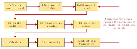
Figure 1.
Main features of the simulators.
Through field analysis and construction scheme design, the simulation object is determined to be the process of coal seam grouting reinforcement. Through analysis, although hydraulic supports support the roadway, the roof and the coal seam are fractured and the reinforced coal seam is still subject to the roof pressure and the bottom support force, as shown in Figure 2. The opening direction of the grouting hole is perpendicular to the coal wall inwards. The slurry diffuses through the grout holes into the coal seam during the grouting process. During this process, the migration of fluid is slow. We can use Darcy’s law to define the seepage process. In the numerical simulation, a coupled model of Darcy’s law and solid mechanics is chosen for the simulation analysis [28,29].
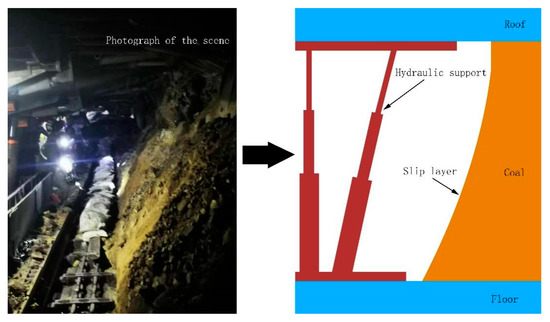
Figure 2.
Alleyway site plan and model drawing.
Before establishing the numerical simulation model, the following assumptions are made for the research object:
(1) It is assumed that the rock and soil layers are dry porous media;
(2) The rock and soil layers are homogeneous and isotropic media, ignoring the influence of anisotropy of rock and soil layers on permeability directivity;
(3) The temperature in the flow field of the grouting reinforcement fluid changes little, so the movement of the grouting reinforcement fluid in the rock soil layer is treated as an isothermal process;
(4) Under isothermal conditions, the dynamic viscosity of grouting and solid–liquid remained unchanged;
(5) Both pore system and fracture system are continuous medium systems;
(6) The grouting reinforcement fluid is regarded as an incompressible Newtonian fluid.
Table 1 lists the physical parameters of the rock and soil layers as well as the relevant parameters for fluid–solid coupling.

Table 1.
Input parameters for all components included in the simulations.
To facilitate the study, we built the influence of grouting reinforcement scope in rock and soil layers; two 100 m × 100 m two-dimensional geotechnical models were built. There are 1 and 3 grouting holes on the models, as shown in Figure 3.
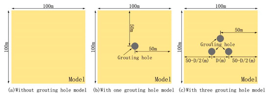
Figure 3.
Numerical simulation modeling.
The single-hole model is perforated and gridded at the center of the 100 m × 100 m two-dimensional geotechnical model. The sequence type of gridding is a physical field control network and the unit size is relatively refined.
Three holes shall be drilled at the center of the 100 m × 100 m two-dimensional geotechnical model and the spacing between the three holes shall be equal. The connecting line of the three holes shall form an equilateral triangle. During grid processing, the sequence type is controlled by user network, the cell size is relatively refined and free triangle network is added.
The power viscosity of the grouting reinforcement material will gradually increase according to the increase of time. Test values for slurry reinforcement at the 90,203 working face of coal seam No. 9 at the Caojiashan coal mine are shown in the table in Figure 4.
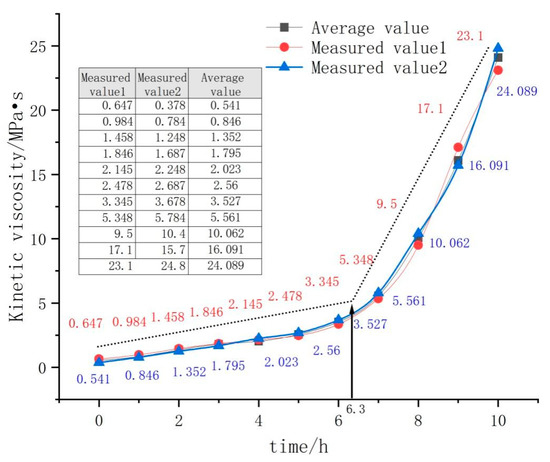
Figure 4.
Kinetic viscosity drawing graph.
The variation curve was plotted based on the time dynamic viscosity data, as shown in Figure 4. As can be seen from the graph, the dynamic viscosity of the grouting reinforcement increases steadily from 0 to 6.3 h, and its value rises rapidly after 6.3 h. In the application of numerical simulation, the average values of Measure value1 and Measure value2 are taken for calculation. In the parameter setting stage of the simulation, the difference function is established and the data in Average value is input into the difference function for the numerical simulation.
4. Results and Discussions
4.1. Influence of Electric Pulse on Fracture Development
The principle of high-voltage electrical pulses in liquids is that a high-voltage electric field accelerates the electrons in the fluid between the electrodes, and the liquid molecules near the electrodes are ionized. The ionized electrons in the liquid are speeded up by the strong electric field between the electrodes, causing more electrons to ionize and forming an electron avalanche. Plasma channels are included in the ionized region of the liquid molecules. With the expansion of the ionization region, a discharge channel is formed between the electrodes and the liquid is broken down. After the discharge channel is generated, a high discharge current will be caused due to the small discharge resistance. The discharge current heats the liquid around the channel, which vaporizes and expands rapidly. The outer edge of the rapidly growing air chamber produces a strong shock wave in the liquid medium. The shock wave acts on the surrounding medium in the form of impulse or shock pressure with the different discharge current and discharge time. The electric pulse grouting reinforcement fracturing is intended to apply an electric pulse during the pressure maintaining process of the mud pump to achieve the superposition effect of the pressure maintaining pressure and the electric pulse shock wave pressure. In order to explain the destructive force of the dynamic pressure impact of the electric pulse shock wave, the numerical simulation method simulates the destructive degree of static pressure fracturing, micro electric pulse fracturing and normal electric pulse fracturing, respectively.
The foundation grouting pressure is the continuous grouting pressure. Whether the pulse pressure is formed or not, the foundation grouting pressure always exists, which can ensure the slow diffusion of the grouting added liquid. As shown in Figure 5, is the foundation grouting pressure, is the pulse grouting pressure.
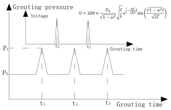
Figure 5.
Base pressure and pulse pressure.
Through numerical simulation, under the influence of different grouting pressures, the damage degree of rock and soil layers is different, as shown in Figure 6, where Figure 6a is the grouting effect diagram of foundation pressure, , and the influence range of grouting fluid is very small (Figure 6b–d). In the third figure, under the premise of ensuring that the foundation pressure, , does not change, after adjusting the peak pressure, , the influence range of the grouting fluid is obviously expanded.
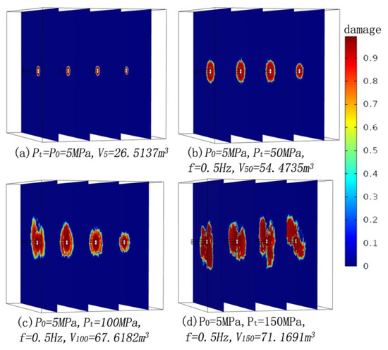
Figure 6.
Geotechnical layer damage map.
By numerical analysis of the data, a diagram of the influence range of fracturing is drawn, as shown in Figure 7. When , the influence range of static pressure cracking is . On this basis, apply and electric pulse; the original static pressure induced fission is changed into dynamic pressure/static pressure combined fracturing, and its fracturing range is obviously increased, ; keep unchanged and increase the electric pulse pressure by and ; its fracturing volume is further increased, but less than the increase range of , and when , the fracture range shows irregular outward expansion. This is because the hole wall can be fully fractured when the electric pulse fracturing pressure is . Because the electric pulse is instantaneous, discharge and the range of vaporized liquid is limited; although the electric pulse fracturing pressure is increased, the electric pulse fracturing volume does not increase correspondingly. When the peak pressure of electric pulse reaches a certain value, the fracture range will continue to expand outward according to the formed texture. Considering the economy, safety and controllability, the reasonable electric pulse pressure .
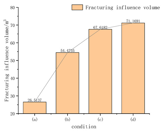
Figure 7.
Fracture impact area.
4.2. Effect of Grouting Time
Select single hole model, set drilling radius R = 0.05 m, grouting pressure . Other parameters are shown in Table 1. Observe the grouting effect within the range of and calculate the penetration of grouting fluid every . Add a filter to the data set of the solution result and set the lower limit of the filter to , i.e., only the pressure area above 0.7 MPa is output. Effective grouting area data calculated for different grouting times are shown in Table 2.
Table 2.
Effective grouting area data.
As for fitting the grouting time and effective reinforcement area in Table 2, the formula for which is as follows:
To accurately determine the point of change in the effective grouting area rise rate, the curvature formula is used, which is as follows:
The curvature of the fitted equation is calculated and the image of the function is obtained as shown in Figure 8.
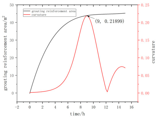
Figure 8.
Fitting the curve and its curvature.
We can see from the figure that with the increase of time, the effective grouting area increases rapidly at first and then slowly. In order to calibrate the optimal grouting time and keep the effective grouting area growing rapidly, the curvature formula of the fitting curve is introduced. From the curvature diagram, it can be seen that when the grouting time is , the curvature reaches the peak value, indicating that the curve fitting is the most curved at this time. Combined with the image, when the grouting time is within the range of , the growth rate of the effective grouting area has slowed down but has always maintained a rapid growth rate; when the grouting time is more than 9 h, after the maximum bending, the growth rate of effective grouting area becomes gentle. The curvature image fluctuates after , which is because a small range of fitting error occurs in the fitting curve of effective grouting area after , leading to the fluctuation of the image calculated by the curvature. This part of the curvature highlight should be considered as error neglect.
To sum up, the grouting time is selected within the range of to ensure the rapid penetration of grout; is the best grouting time.
4.3. Influence of Hole Spacing
Based on the conclusions in Section 4.2, an optimal grouting time of 9 h is chosen and a three-hole model is used. Fix the drilling radius (the drilling radius is much smaller than the hole spacing); fix variables such as the permeability of the grouting reinforcement fluid; set the effective grouting pressure to 0.7 MPa. The pressure cloud output in comsol is shown in Figure 9.
Figure 9.
Three-hole pressure cloud map.
Set the hole spacing as a variable and parametrically scan it. Within the range of to , conduct a simulation every and calculate the effective grouting area.
Add a filter to the data set of the solution result and set the lower limit of the filter to , i.e., only the pressure area above is output. The surface integral is calculated in the derived value. The influence of grouting time on the effective grouting area is calculated under the change of different drilling intervals. The curve of effective grouting area changing with time is shown in Figure 10.
Figure 10.
Effect of hole spacing on effective grouting area.
We can see from Figure 10 that the effective grouting area increases rapidly with the increase of hole spacing in the range of 0–9.5 m. We call the area in the range of 0–9.5 m the Overlap zone; when the hole spacing is 9.5 m, the effective grouting area reaches the maximum value of . The pressure cloud diagram and the effective grouting area diagram at this time are shown in Figure 11. When the hole spacing is 9.5–13.5 m, the grouting area decreases rapidly, and we call the area within 9.5–13.5 m the Central blank expansion zone. After the hole spacing is larger than 13.5 m, the effective grouting area is stable and the change is small; we call this part of the area the Grouting area separation zone.
Figure 11.
Effective grouting area.
Analyze the influence of hole spacing on the effective grouting area. When the parameters such as grouting hole radius, grouting pressure and grouting time are determined, the slurry diffusion radius remains unchanged; that is, the influence range of effective grouting pressure remains unchanged. When the drilling interval is too small, the effective grouting area is excessively overlapped, resulting in the reduction of the overall area and the waste of grout. At the same time, the number of holes drilled per unit area increases, resulting in an increase in the construction time cost and labor cost; when the hole spacing and grouting increase, the effective grouting area increases rapidly, forming a large grouting reinforcement area. However, when the hole spacing is greater than the optimal value, a large blank area will be formed in the middle of the three holes which will affect the stability of grouting reinforcement and even lead to the failure of the entire grouting reinforcement construction. Therefore, the hole spacing cannot be increased excessively; when the hole spacing is , the effective grouting area reaches the maximum. At this time, there will also be a blank area in the middle of the three holes; however, at this time, the blank area is small, and the effective reinforcement area around the blank area will form a support.
To sum up, in the three hole grouting model, the optimal hole spacing is . For the convenience of on-site construction, the hole spacing is set as 10 m.
5. Grouting Reinforcement of Coal Mine Working Face
5.1. On Site Grouting Technology
The working face of No. 9 coal seam 90,203 in the Caojiashan coal mine is 5 m high, the floor of the roadway is stable, the top plate and the coal seam in the working face are in a loose and broken state and even the exposed coal wall has the potential to crumble. There is hydraulic bracket support in the roadway. Due to the damaged roof plate and coal seam in front, the hydraulic bracket cannot advance, putting the coal seam mining work at a standstill. After the coal seam sampling analysis, the inner coal body is soft and wet. It is challenging to reinforce according to conventional crack grouting method.
A working face of 50 m in length along the direction of the roadway was used as a test area for the electrical pulse grouting reinforcement. Two rows of grouting holes were drilled laterally using a staggered drilling pattern. The top row of holes is centred 1 m from the top plate and perforated at an upward sloping angle to a depth of 15 m. The bottom row of holes is centred 1 m from the bottom plate and perforated at an upward sloping angle to a smaller depth of 20 m, as shown in Figure 12a. The line joining the centres of the three adjacent holes in the upper and lower rows is an equilateral triangle and the side of this equilateral triangle is 10 m long; as shown in Figure 12b.
Figure 12.
Perforation angle and sampling point.
To facilitate the detection of the grouting effect, four sampling points are selected on the coal wall of the test area. The sampling point selection method is as follows: Point A is the mid-point of two neighboring grout holes in the same line; Point B is the place where the coal wall is close to the roof; Point C is the coal wall near the floor; Point D is the middle point of two adjacent drill holes in different rows.
The realization method of electric pulse reinforcement grouting at the test site is shown in Figure 13. To summarise: (1) Two high-voltage electrodes, positive and negative, are placed in the grout hole. The wires on the electrodes are connected to an external electrical pulse generator via a lead pipe. At the same time, a grouting pipe is prepared. The grouting pipe and the wire tube are simultaneously supported at the grouting hole opening; (2) Cement mortar is used to block the grouting orifice; (3) We can use the grout pump to inject the grout reinforcement fluid into the borehole through the grouting pipe and observe the grouting pressure. When the grouting pressure reaches , the grouting pump will start the pressure maintaining grouting mode; (4) After the completion of procedure (3), according to the grouting frequency and peak grouting pressure set in the electric pulse reinforcement method, the electric pulse grouting reinforcement is started; (5) We determine whether the grouting and reinforcement process is completed by detecting the injection amount of reinforcement grouting fluid. When the last two electric pulses discharge, the increase amount of grouting and reinforcement fluid is less than the threshold value and it is deemed that the electric pulse grouting and reinforcement are completed; (6) We maintain the pressure until the grouting reinforcement liquid coagulates; (7) We start the shearer, excavate at the current working face, advance the working face forward for 12 m, and then stop to the next working face. We repeat the above steps to reinforce the roof at the new working face.
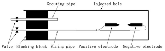
Figure 13.
Electric pulse discharge device in the grouting hole.
5.2. Grouting Materials
The slurry reinforcement solution was configured according to the proportioning instructions of high-efficiency high-strength reinforcement material, i.e., high-efficiency reinforcement material No. 1:high-efficiency reinforcement material No. 2:water = 40 kg:2 kg:10–15 kg.
The setting characteristics of this grouting reinforcement solution were tested, analyzed and compared with ordinary cement slurry. After a long period of solidification, the compressive strength of both cement and grouting reinforcement material is stable at about 40 MPa, but the grouting reinforcement material can solidify rapidly in the early stage and the compressive strength can reach more than 30 MPa in a short time; the compressive strength of the grouting reinforcement liquid rises rapidly in the early stage and the strength keeps rising steadily in the middle and late stage; the hardening speed of the ordinary cement slurry is slower. Comparing the compressive strength data in the first 10 h, the hardening speed of the slurry reinforcement is significantly better than that of ordinary cement, as shown in Figure 14.
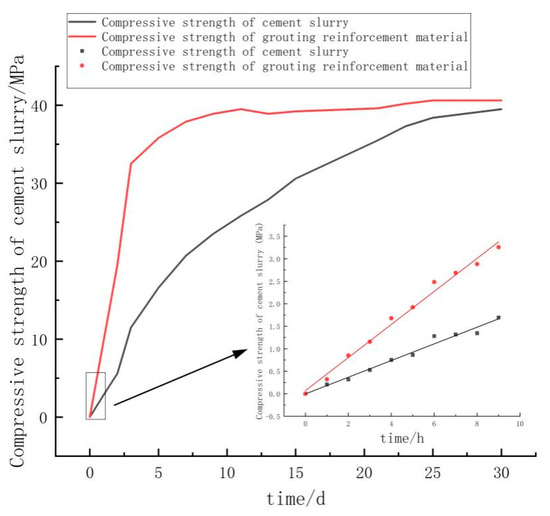
Figure 14.
Compressive curve diagram.
The grouting reinforcement has the following characteristics: (a) good fluidity in the early stage, no precipitation of water, no delamination; (b) micro-expansion characteristics, grouting with full and early strength, firm bonding; (c) rapid growth of strength in the early stage; (d) stable strength in the middle and late stage, 24 h strength can reach more than 25 MPa, 3d strength can reach more than 35 MPa, final strength can reach 40–60 MPa; (e) it can be seen from the proportioning that the grouting reinforcement contains more water, which can be tested and can form the plasma channel smoothly under the action of high voltage electric pulse.
5.3. Effect of Grouting Reinforcement
A thin-walled drill was used to drill and take samples from the side of the coal wall that had been reinforced by grouting, and the specimens were tested on a pressure testing machine for their axial compressive strength. The test data are shown in Figure 15. The compressive strength of the specimen at sampling point C is shown in Figure 15a,b, and the compressive strength at this point is low, with values ranging from because the double rows of boreholes are all tilted upward for drilling, resulting in a lower reinforcement effect. Figure 15c,d both show the compressive strength of the specimen at sampling point A. The values are . Figure 15e,f show the compressive strength of the specimens at sampling point D. The values are . Figure 15g,h show the compressive strength of the specimens at sampling point B. The values are , where the compressive strength is the highest and the reinforcement effect is the best. The compressive strength data of the specimens show that the compressive strength gradually increases when sampling upward from the bottom plate, and the reinforcement effect on the top plate is obvious.
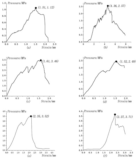
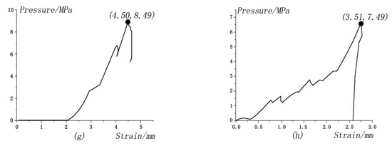
Figure 15.
Sample axial compressive strength data.
Through the axial compressive strength test, the compressive strength of the broken coal seam specimen after electric pulse grouting reinforcement has been greatly improved, which can ensure that the top plate in front of the working face is completely reinforced, eliminating the risk of the top plate falling off and allowing the hydraulic support to move forward smoothly.
6. Conclusions
In this study, the feasibility of combining conventional grouting technology with electric pulse grouting reinforcement technology was analyzed, and numerical simulations and field verification were conducted. Through the simulation method of fluid–solid coupling, the influencing factors of the electric pulse grouting reinforcement effect were studied, and the simulation analysis of the influence of electric pulse grouting on the geotechnical layer, grouting time and drilling spacing was carried out to determine the best parameters of electric pulse grouting reinforcement technology in the treatment of soft roof slab in the Caojiashan coal mine. The following main conclusions were drawn.
(1) Through numerical simulation, comparing and analyzing the damage degree and slurry diffusion area data of conventional fracture grouting and electric pulse grouting on the rock, we can see that the rock damage degree is greater, and the slurry diffusion area is wider when using the electric pulse grouting reinforcement method. When the static grouting pressure is 5 MPa and the peak electric pulse pressure is 100 MPa, it is the most economical and reasonable electric pulse parameter. The grouting time and the hole spacing of grouting holes greatly influence the overall grouting effect. Through numerical simulation, we can see that the optimal value of grouting reinforcement time is 9 h and the optimal value of hole spacing is 10 m;
(2) In the treatment of grouting reinforcement of soft roof plate in the Caojiashan coal mine, using the optimal parameters after numerical simulation, the compressive strengths of the reinforced soft roof plates were all above , which were well managed and enabled the hydraulic bracket to advance each time, proving the feasibility of electric pulse grouting reinforcement technology;
(3) The combination of conventional grouting technology and electric pulse grouting reinforcement technology can increase the reinforcement liquid in a short time, so that the reinforcement liquid can spread rapidly and the reinforced area can reach the maximum in a short time. In engineering applications, the reinforcement treatment cycle can be shortened and the treatment area receives better reinforcement results. This provides an effective solution for the same type of engineering applications.
Author Contributions
Writing—original draft preparation, X.Q.; Software, R.Z. and X.Z. (Xiaogang Zhang); Methodology, R.Z.; Validation, L.Z.; Formal analysis, L.Z.; Validation, X.Z. (Xinghua Zhang) All authors have read and agreed to the published version of the manuscript.
Funding
The authors would like to give their sincere gratitude for the financial support from the National Natural Science Foundation of China (Grant No. 42102222).
Institutional Review Board Statement
Not applicable.
Informed Consent Statement
Not applicable.
Data Availability Statement
Not applicable.
Acknowledgments
Many thanks to all the contributions and support given by the authors in preparing the writing of this article.
Conflicts of Interest
The authors declare no conflict of interest.
References
- Pan, R.; Wang, Q.; Jiang, B.; Li, S.C.; Sun, H.B.; Qin, Q.; Yu, H.C.; Lu, W. Failure of bolt support and experimental study on the parameters of bolt-grouting for supporting the roadways in deep coal seam. Eng. Fail. Anal. 2017, 80, 218–233. [Google Scholar] [CrossRef]
- Wang, K.; Wang, L.G.; Ren, B. Failure Mechanism Analysis and Support Technology for Roadway Tunnel in Fault Fracture Zone: A Case Study. Energies 2021, 14, 3767. [Google Scholar] [CrossRef]
- Wang, W.; Pan, Y.S.; Xiao, Y.H. Synergistic Mechanism and Technology of Cable Bolt Resin Anchoring for Roadway Roofs with Weak Interlayers. Rock Mech. Rock Eng. 2022, 55, 3451–3472. [Google Scholar] [CrossRef]
- Jia, H.S.; Wang, Y.W.; Liu, S.W.; Li, Y.E.; Shao, R.L.; Wang, G.Y.; Guo, Z.Q.; Wang, L. Experimental study on double cuneiform reamed anchorages for cable bolt boreholes in soft rock. Int. J. Rock Mech. Min. Sci. 2022, 158, 10. [Google Scholar] [CrossRef]
- Shan, R.L.; Liu, W.J.; Li, G.Z.; Liang, C.; Shi, S.G.; Chen, Y.; Zhang, S.P. Experimental Study on the Shear Mechanical Properties of Anchor Cable with C-Shaped Tube. Sustainability 2022, 14, 9616. [Google Scholar] [CrossRef]
- Lu, H.F.; Yin, J.L.; Liu, Q.S.; Cao, A.D.; Wei, A.C.; Zhang, K. A self-dissolved grouting reinforcement method for water-rich soft rock roadway. Bull. Eng. Geol. Environ. 2022, 81, 15. [Google Scholar] [CrossRef]
- Zhao, C.X.; Li, Y.M.; Liu, G.; Meng, X.R. Mechanism analysis and control technology of surrounding rock failure in deep soft rock roadway. Eng. Fail. Anal. 2020, 115, 14. [Google Scholar] [CrossRef]
- Chen, S.M.; Wu, A.X.; Wang, Y.M.; Chen, X.; Yan, R.F.; Ma, H.J. Study on repair control technology of soft surrounding rock roadway and its application. Eng. Fail. Anal. 2018, 92, 443–455. [Google Scholar] [CrossRef]
- Li, Z.P.; Li, S.C.; Liu, H.J.; Zhang, Q.S.; Liu, Y.A. Experimental Study on the Reinforcement Mechanism of Segmented Split Grouting in a Soft Filling Medium. Processes 2018, 6, 131. [Google Scholar] [CrossRef]
- Li, X.L.; Guo, X.L.; Sun, G. Grouting Reinforcement Mechanism and Multimodel Simulation Analysis of Longwall Goaf. Geofluids 2021, 2021, 13. [Google Scholar] [CrossRef]
- Yan, S.Y.; Chu, H.B.; Jiao, H.Z.; Chen, X.M.; Wang, C. Long-Distance Advanced Pre-grouting Layer Flexible Reinforcement Mechanism and Its Application in Large Mining Height Coal Face. Min. Met. Explor. 2022, 39, 2379–2392. [Google Scholar] [CrossRef]
- Hu, Z.Q.; Ma, B.; Chen, X.Z.; Chen, L.L. Study on Sensitivity Parameters Analysis of Grouting Reinforcement Underpassing Existing Subway Tunnel by Numerical Modeling. Adv. Civ. Eng. 2021, 2021, 13. [Google Scholar] [CrossRef]
- Chen, J.; Chen, X.L.; Ding, F.X.; Xiang, P.; Yang, C.Q.; Liu, Y.L.; Xu, F. Mechanical performance of overlap connections with grout-filled anchor reinforcements in embedded metal corrugated pipe. Arch. Civ. Mech. Eng. 2020, 20, 12. [Google Scholar] [CrossRef]
- Ni, Z.; Lin, B.Q.; Zhang, X.L.; Cao, X.; Zhong, L.B.; Gao, Y.B. Experimental study on the effect of high-voltage electrical pulses on the nanoscale pore structure of coal. Fuel 2021, 306, 11. [Google Scholar] [CrossRef]
- Bao, X.K.; Guo, J.Y.; Liu, Y.; Zhao, G.; Cao, J.X.; Wu, J.W.; Zhao, J.C. Damage characteristics and laws of micro-crack of underwater electric pulse fracturing coal-rock mass. Theor. Appl. Fract. Mech. 2021, 111, 17. [Google Scholar] [CrossRef]
- Li, C.X.; Nie, B.S.; Zhang, Z.H.; Liu, X.F.; Zhao, Z.Y.; Zhang, C.C.; Lu, W.D. Experimental Study of the Structural Damage to Coal Treated by a High-Voltage Electric Pulse Discharge in Water. Energy Fuels 2022, 36, 6280–6291. [Google Scholar] [CrossRef]
- Wang, Y.H.; Yang, W.; Lin, B.Q.; Yan, F.Z. Effects of different conductive ions on pore-structure evolution of medium and high-rank coal bodies induced by electric pulses. Fuel 2021, 293, 9. [Google Scholar] [CrossRef]
- Rosanov, N.N. The Formation of Three-Dimensional Unipolar Pulses upon Motion of Charges in a Vacuum. Opt. Spectrosc. 2020, 128, 92–93. [Google Scholar] [CrossRef]
- Rosanov, N.N. Electric Area of an Extremely Short Pulse and Moment of Force. Opt. Spectrosc. 2018, 125, 1012–1013. [Google Scholar] [CrossRef]
- Gao, Y.B.; Han, P.Z.; Wang, F.; Cao, J.; Zhang, S.Q. Study on the Characteristics of Water Jet Breaking Coal Rock in a Drilling Hole. Sustainability 2022, 14, 8258. [Google Scholar] [CrossRef]
- Kreilinger, I.L.; Moeller, K.; Pixner, S. Mental simulation and its influence on finger-based numerical representations. Trends Neurosci. Educ. 2021, 25, 100167. [Google Scholar] [CrossRef] [PubMed]
- Gao, W.T.; Zhang, Y.F.; Du, G.H.; Pu, T.; Li, N.M. Comprehensive Comparison of a High-Speed Permanent Magnet Synchronous Motor Considering Rotor Length-Diameter Ratio. Energies 2022, 15, 5256. [Google Scholar] [CrossRef]
- Bi, G.N.; Xiao, X.H.; Li, G.K. Development and Validation of Multiple Physical Fields Coupling Model for Microwave-assisted Extraction. Chem. J. Chin. Univ.-Chin. 2022, 43, 56–66. [Google Scholar]
- Liu, Y.; Liu, X.; Aori, G.; Li, J.; Ye, H.Y.; Koh, S.W.; Zhang, G.Q. Location optimize of press-pack IGBT chip. In Proceedings of the 20th International Conference on Electronic Packaging Technology (ICEPT), Hong Kong, China, 12–15 August 2019. [Google Scholar]
- Paz-Garcia, J.M.; Villen-Guzman, M.; Cerrillo-Gonzalez, M.M.; Rodriguez-Maroto, J.M.; Vereda, C.; Gomez-Lahoz, C. Teaching Chemical Engineering Using Comsol Multiphysics. In Proceedings of the 13th International Technology, Education and Development Conference (INTED), Valencia, Spain, 11–13 March 2019; Iated-Int Assoc Technology Education & Development: Valencia, Spain, 2019; pp. 8848–8852. [Google Scholar]
- Ye, X.L. Research and Application of Multi-dimension Numerical Simulation Optimization for SCR DeNOx Flow Field. In Proceedings of the 3rd International Conference on Advances in Energy Resources and Environment Engineering (ICAESEE), Harbin, China, 8–10 December 2017; Iop Publishing Ltd.: Harbin, China, 2017. [Google Scholar]
- Cai, Y.M.; Zhang, J.B.; Yu, W.Z. A Predictor-Corrector Method for Power System Variable Step Numerical Simulation. IEEE Trans. Power Syst. 2019, 34, 3283–3285. [Google Scholar] [CrossRef]
- Uscanga-Ramos, M.A.; Lopez-Sanchez, E.; Martinez-Navarrete, N.; Garcia-Alvarado, M.A.; Salgado-Cervantes, M.A. Analytical solution of freeze-drying mathematical model based in Darcy’s law: Application to an orange juice-based cake. Cyta-J. Food 2021, 19, 265–272. [Google Scholar] [CrossRef]
- Zolotukhin, A.B.; Gayubov, A.T. Semi-analytical Approach to Modeling Forchheimer Flow in Porous Media at Meso- and Macroscales. Transp. Porous Media 2021, 136, 715–741. [Google Scholar] [CrossRef]


Disclaimer/Publisher’s Note: The statements, opinions and data contained in all publications are solely those of the individual author(s) and contributor(s) and not of MDPI and/or the editor(s). MDPI and/or the editor(s) disclaim responsibility for any injury to people or property resulting from any ideas, methods, instructions or products referred to in the content. |
© 2023 by the authors. Licensee MDPI, Basel, Switzerland. This article is an open access article distributed under the terms and conditions of the Creative Commons Attribution (CC BY) license (https://creativecommons.org/licenses/by/4.0/).