Article

Safety Analysis of Rebar Corrosion Depth at the Moment of Corrosion-Induced Cover Cracking

1
School of Civil Engineering, Xuzhou Institute of Technology, Xuzhou 221111, China
2
School of Mines, China University of Mining and Technology, Xuzhou 221116, China
*
Authors to whom correspondence should be addressed.
Sustainability 2023, 15(3), 2491; https://doi.org/10.3390/su15032491
Submission received: 17 November 2022 / Revised: 16 January 2023 / Accepted: 19 January 2023 / Published: 30 January 2023

Abstract

:
Concrete cover cracking induced by reinforcement corrosion is an important indication of the durability limit state for reinforced concrete (RC) structures and can be used to determine the structural service life. The process of rebar corrosion from the beginning of rusting to the occurrence of cover cracking due to corrosion expansion can be divided into two phases: the phase of the free expansion of the corrosion product and the phase of cover cracking. Based on the assumption of the uniform corrosion of the reinforcement, one model for predicting the reinforcement corrosion depth from corrosion initiation to cover cracking was established according to the cylindrical cavity expansion theory. The main factors affecting the reinforcement corrosion depth were analyzed. The main factors affecting the corrosion depth of reinforcement were analyzed. The quantitative sensitivity analysis of the factors influencing the calculation formula shows that the depth of reinforcement corrosion and the thickness of the concrete protective layer are approximately linearly increasing, with a growth rate of 0.2366 μm/mm; the diameter of the reinforcement is approximately linearly decreasing, with a decrease rate of 0.2122 μm/mm; the volume expansion rate of rust is approximately power function decreasing; the overall influence range of the yield criterion selection parameter is 0.15 μm; for the concrete strength grade, the overall influence range is 0.1 μm. The coefficient of determination R2 is 0.87, and the overall accuracy of the calculated formula is high, which can be used to predict the service life of reinforced concrete structures and guide the durability design in combination with the research results on the corrosion rate of reinforcement under different environments.

1. Introduction

The durability of a concrete structure is the ability of the structure to maintain its safety and serviceability without additional maintenance and reinforcement costs under the action of various environmental conditions within the service life specified in the design [1]. Under the action of an erosive environment, the degradation of performance of structural members caused by steel corrosion or even damage is one of the most important manifestations of the durability failure of concrete structures [2]. The volume of the corrosion products of the reinforcement after rusting is larger than the volume of the corresponding reinforcement, which will produce radial extrusion on the concrete around the reinforcement, i.e., rust expansion force. As the corrosion of reinforcement increases, the rust expansion force increases, and the concrete protective layer is cracked by tension. Once the concrete protective layer is cracked, the corrosion rate of reinforcement will be accelerated, which will cause the protective layer to spill and delamination, and the structural performance will be reduced. Therefore, rust and swelling cracking of the concrete protection layer is usually considered as one of the signs of a normal service limit state of the concrete structure [3,4].
Many scholars have conducted a lot of research on the rust swelling cracking of the concrete protective layer. An elastic analysis of the rust swelling cracking process of the concrete protective layer was carried out [5]. The rust distribution and cracking of corner reinforcement in concrete have been studied and a conceptual model of rust growth has been proposed [6]. Some studies have used elastic mechanics to give the equation for the calculation of the circumferential stress in the uncracked portion of a cylinder with unit length radius [7]. There has also been research to calculate the stress in the uncracked portion of a cylinder by using the elastic mechanics. There was also a study that proposed a formula for calculating the rusting and swelling force of reinforcement by the mechanism of the rusting and swelling force of reinforcement [8]. Using the theory of circular hole expansion, Hui Jiang et al. analyzed the internal cracking of the concrete protective layer after the free expansion of rust filled the void at the interface between the concrete and the reinforcement [9]. In this process, the computational equation for the depth of corrosion of the reinforcement at the moment of rust expansion and internal cracking was also established. Research was conducted to evaluate the concrete cracking and reinforcement strain behavior due to reinforcement corrosion by a systematic approach [10]. Penggang Wang et al. [11] investigated the rationality of the concrete protective layer thickness measurement method and proposed predictive measures for structural life. Some scholars modeled the problem through hypothetical argumentation studies. Assuming equal rust layer thickness around the reinforcement and considering the softening characteristics of concrete, the concrete protective layer rust damage model was proposed [12]; assuming that the concrete satisfies the Mohr–Coulomb yield criterion and using the theory of circular hole expansion, the concrete protective layer rust expansion cracking and expansion model was established [13]. Meanwhile, finite element analysis has also been widely used to study rust expansion cracking of the concrete protective layer [14,15,16,17,18].
Steel corrosion is an unavoidable problem in buildings, and the study of its mechanism helps to ensure the safety of buildings within a specified period of time. [19,20]. Modern buildings require a certain level of seismic resistance, and natural and man-made corrosion of reinforcement affects building safety equally [21]. Whereas seismic vulnerability is usually assessed by a risk index, studies have shown a correlation between the level of reinforcement corrosion and the seismic risk index. [22] The study of reinforcement corrosion depth can likewise provide a reference for assessing seismic resilience.
Most of the calculation formulae established by the existing research results are based on their own test data or finite element analysis results, and the theoretical research is also limited to the elastic mechanical analysis, which makes the calculation formulae have certain limitations. In this paper, we use the theory of circular hole expansion and the unified strength theory to conduct an elasto-plastic analysis of the cracking process of the concrete protective layer caused by steel corrosion, establish the corresponding calculation formula for the depth of steel corrosion, and make a quantitative sensitivity analysis of the main influencing factors of the calculation formula. The aim is to provide an elasto-plastic theory solution, and at the same time, the concrete yield criterion as an influencing factor is introduced and initially discussed.

2. Analytical Model for Rust and Swelling Cracking of the Concrete Protective Layer

2.1. Basic Model

Rust expansion cracking of the concrete protective layer starts from the de-passivation of reinforcement and can be roughly divided into two stages: (1) the rust-free expansion stage. At this stage, the reinforcement begins to de-passivate to the point where rust fills the void at the intersection of the reinforcement and concrete and begins to generate rust expansion forces. Due to the inherent material characteristics of concrete and the production process, there are some capillaries and tiny voids in the cement stone at the junction of steel and concrete. The rust from the corrosion of the reinforcement will fill in these capillary holes and will not produce rust expansion force on the peripheral concrete work until the capillary holes are filled. (2) The oncrete protective layer cracking stage. This stage is marked by the beginning of the rust expansion force on the concrete and ends with the cracking of the concrete protection layer. When the reinforcing steel corrosion products fill the gap between the reinforcing steel and concrete interface, the reinforcing steel continues to rust, and the rust expansion force begins to generate and gradually increases. The concrete protective layer enters the plastic stage from the elastic stage, and the plastic zone expands continuously. When the rust expansion force increases to a certain degree, the whole concrete protective layer reaches the maximum load-bearing capacity and cracks. Figure 1 shows the analysis of the two stages of rust and swelling cracking of the concrete protection layer.
Based on the two stages of concrete protective layer rust and expansion cracking, the corrosion depth of the reinforcement at the moment of concrete protective layer expansion cracking can be divided into two parts: (1) the corrosion depth of reinforcement δ 1 when the corrosion products fill the void at the intersection of reinforcement and concrete; and (2) the corrosion depth of reinforcement δ 2 when the corrosion products generate rust and expansion force leading to concrete protective layer cracking. The depth of reinforcement δ at the moment of rust expansion and cracking of the concrete protection layer is:
δ = δ 1 + δ 2

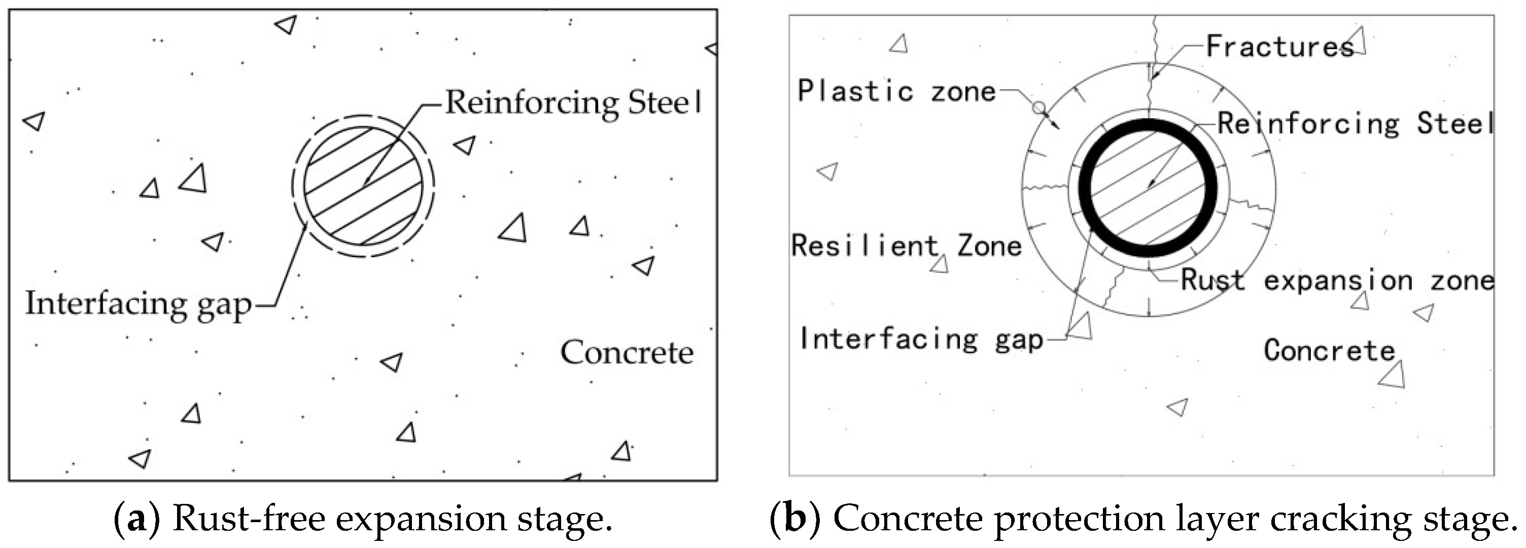
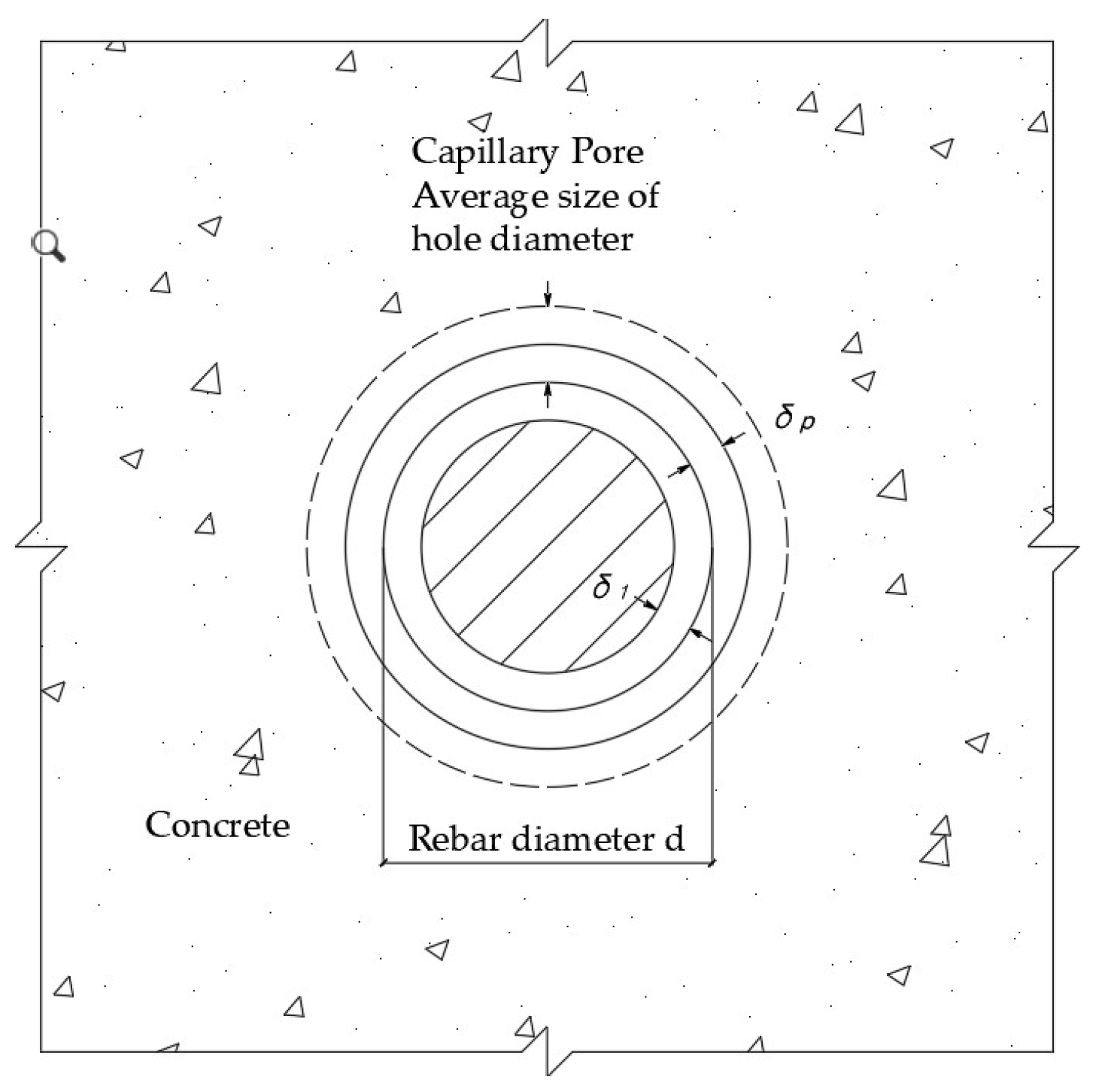
2.2. Rust Depth of Reinforcement in the Free Expansion Phase of Rust

The depth of corrosion of the reinforcement in the free expansion phase of rust depends on the volume of the capillary pores at the interface between the reinforcement and the concrete. The volume of the pores at the interface between the reinforcement and concrete, i.e., the volume of rust filled into the capillary pore V p , can be converted into a uniform rust layer thickness δ p at the periphery of the reinforcement, and δ p can be further converted into the depth of corrosion δ 1 of the reinforcement by geometric relationships. Assuming that the pores are uniformly distributed in the cement stone, it is known from Figure 2 that:
δ p = V p π d = P v p π d d p π d = P v p d p
where V p is the volume of capillary holes at the intersection of reinforcing steel and concrete on the longitudinal unit length of reinforced concrete members; δ p is the thickness of the converted rust layer ( μ m ); P v p is the volume of pores percentage of cementite; d is the diameter of reinforcing steel, and the unit is considered by μ m in the calculation; and d p is the average pore size of pores ( μ m ).
The geometric conversion shows that the calculation formula for the depth of corrosion of the reinforcement is:
δ 1 = d 2 d 2 4 d δ p + δ p 2 n 1
where n is the volume expansion rate of rust, generally taken as n = 2 ~ 4 [23].
Many factors affect the size of cement stone pores in concrete. Their size mainly depends on the concrete water–cement ratio, but also the construction level and maintenance conditions. The holes generally account for about 0–40% of the total volume of cement stone, while the hole size ranges from 1 to 50   μ m [24]. According to the formula, the fluctuation range of δ p   is about 1~20 μ m ; its value changes with different concrete strength levels amd construction and maintenance conditions. In the absence of concrete material parameters, the calculation can be taken as the mean value of 10   μ m . According to the conversion relationship of the formula, the depth of corrosion of the reinforcement δ 1   was calculated. The recommended value of δ 1 in the literature [6] is 12.5   μ m .

2.3. Depth of Corrosion of Reinforcement in the Cracking Stage of the Concrete Protective Layer

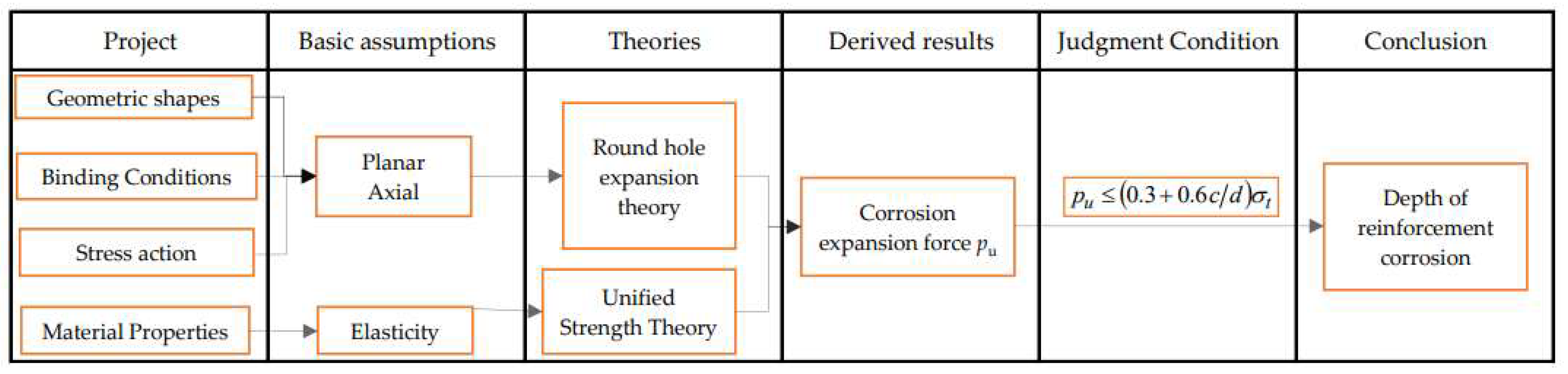
2.3.1. Basic Assumptions

The rusting and cracking of the concrete protective layer caused by reinforcement corrosion is a random process, which is influenced by many factors, such as material strength, concrete strength, environmental factors, etc. From the way of generation, the influencing factors can be divided into man-made corrosion and natural corrosion, and this paper mainly considers its natural corrosion situation. Before conducting the theoretical analysis, we make the following basic assumptions. The basic flow chart is shown in Figure 3.
(1)
Reinforced concrete is isotropic and concrete is an ideal elastic–plastic material, which satisfies the unified strength theory. The volume of reinforcing steel corrosion products expands at a uniform linear law, producing a uniformly distributed rust expansion force.
(2)
The geometry of the reinforced concrete to be analyzed as well as the constrained boundaries are symmetrical to the central axis of the reinforcement, and the stresses generated in the concrete are caused only by the corrosion of the reinforcement, which is simplified to a plane strain axisymmetric problem.
(3)
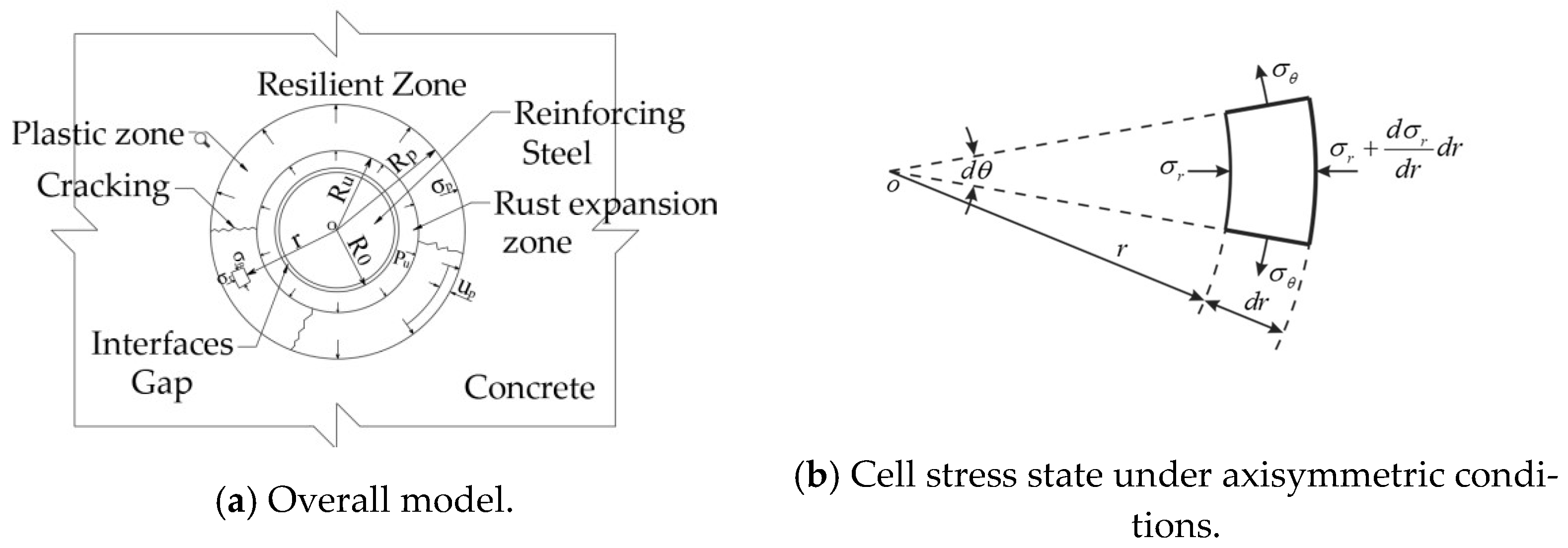
Under the action of a uniformly distributed rust expansion force, the cylindrical concrete around the reinforcement is composed of a plastic zone and an elastic zone from the inside to the outside. Among them, the plastic zone expands continuously with the increase in rust expansion force, and the rust expansion cracking model of the concrete protection layer is shown in Figure 4. In the figure: r   is the radius within the differential unit; σ r is the radial positive stress; σ θ is the circumferential positive stress; σ p is the radial pressure in the plastic zone of the circular hole; p u is the final internal pressure; u p is the small radial deformation in the plastic zone (caused by the radial stress action in the elastic zone); R p is the radius of the plastic zone during rust expansion; R 0 is the initial radius of the circular hole (due to the small gap at the intersection relative to R 0 , the approximation is taken as R 0 = d 2 ); and R u is the final radius after expansion.
Uniform rusting of reinforcement bars, based on the deformation model of reinforcement bars [25]:
R u = R 0 1 + n 1 ρ t
The radius of the uncorroded reinforcement is:
R = R 0 δ 2 = R 0 1 ρ t
where ρ t is the corrosion rate of reinforcing steel.

2.3.2. Theoretical Derivation

The rust and swelling cracking model of the concrete protection layer shown in Figure 3 is a plane strain axisymmetric problem and is analyzed using the polar coordinate system. Considering the equilibrium of the unit force system, the equilibrium differential equation for the plane strain axisymmetric problem can be obtained as:
d σ r d r + σ r σ θ r = 0
The unified strength theory is used as a boundary-yielding criterion in the plastic zone of concrete. The unified strength theory for the principal stress form is [26].
σ 1 α 1 + b b σ 2 + σ 3 = σ t   σ 2 σ 1 + α σ 3 1 + α
1 1 + b σ 1 + b σ 2 α σ 3 = σ t   σ 2 σ 1 + α σ 3 1 + α
where α = σ t σ c   is the tensile strength ratio of concrete and b is the yield criterion selection parameter introduced in the unified strength theory, which reflects the intermediate principal shear stress and the degree of influence of positive stress on the corresponding surface on material damage.
The analytical equations of stress and radial displacement at any point within the elastic zone are solved using the reaming theory, where the stress is [25]:
σ r = R 0 2 p r 2
σ θ = R 0 2 p r 2 = σ r
when r > R p , the radial displacement is:
u r = 1 + ν E r σ r
σ θ = σ r > 0 , from the elastodynamic stress component of the plane strain axisymmetric problem, it is known that:   τ r θ = τ θ r = 0 . Therefore, σ 1 = σ θ , σ 2 = ν   σ r + σ θ = 0 , σ 3 = σ r . For concrete materials 0 < α < 1 , by substituting these relations into the unified strength theoretical and formula, the following equation can be obtained:
0 = σ 2 σ 1 + α σ 3 1 + α = σ θ + α σ r 1 + α
Therefore, the following relationship Equation (7) is used:
σ θ α 1 + b σ r = σ t
Substituting Equation (13) into Equation (6) yields:
d σ r d r + 1 + b α 1 + b σ r r σ t 1 r = 0
The above equation is a linear differential equation of the first order. The first-order linear differential equation can be solved by first finding the general solution of the corresponding chi-square equation and then the special solution. Using boundary conditions, when r = R u and σ r = p u , the solution of Equation (14) is:
σ r = σ t 1 + b 1 + b α p u + σ t 1 + b 1 + b α R u r 1 + b α 1 + b
The volume change after the expansion of the cylindrical hole is equal to the sum of the volume change in the elastic zone and the volume change in the plastic zone:
π R u 2 π R 0 2 = π R p 2 π R p u p 2 + π R p 2 R u 2 Δ
where Δ means the average volume strain in the plastic zone. In this paper, we assume that the average volume strain in the plastic zone of concrete Δ = 0.001 . This value is derived from the existing literature and has been validated for its reasonableness [27].
The final value of the pressure in the hole p u and the maximum radius of the plastic zone R p can be determined using the relationship of the volume change.
Expand Equation (16), omitting u p 2 :
1 + Δ = 2 u p R p R u 2 + R p 2 R u 2 Δ + R 0 2 R u 2
when r = R p , from the expression for the radial displacement in the elastic zone, the following expressions can be calculated:
u p = 1 + ν E R p σ p
Equation (15) shows that:
σ p = σ t 1 + b 1 + b α p u + σ t 1 + b 1 + b α R u R p 1 + b α 1 + b
At the junction of the elastic and plastic zones ( r = R p ), the stresses σ r and σ θ should satisfy the unified strength theory equation, and should satisfy Equation (10), combined with Equations (10) and (13), by simplification to obtain:
σ p = σ r = 1 + b 1 + b + α σ t
Substituting the above equation into Equation (19) yields:
σ p = 1 + b 1 + b + α σ t = σ t 1 + b 1 + b α p u + σ t 1 + b 1 + b α R u R p 1 + b α 1 + b
Substituting Equation (21) into Equation (17), we obtain by simplification:
R p R u = 1 + Δ R 0 2 R u 2 2 1 + ν E 1 + b 1 + b + α σ t + Δ
Knowing the value of R p R u , we can calculate the final value of pressure in the cylindrical hole p u . The value of p u can be solved from Equation (21):
p u = σ t 1 + b 1 + b α + σ t 1 + b 1 + b α + 1 + b 1 + b + α σ t 1 + Δ R 0 2 R u 2 2 1 + ν E 1 + b 1 + b + α σ t + Δ 1 + b α 2 1 + b
Substituting Equation (23) into Equation (15), we can obtain the radial stress value σ r in the plastic zone, and then substituting into the yield condition Equation (13), we can further obtain the circumferential stress value σ θ in the plastic zone.

2.3.3. Depth of Corrosion of Reinforcing Steel When the Concrete Protective Layer Is Rusted and Expanded and Cracked

The rust expansion force corresponding to the cracking of the concrete protective layer is defined as the critical reinforcement rust expansion force. It is assumed that when the rust expansion force reaches the critical reinforcement rust expansion force, the concrete protection layer is rusted and cracked, and the structure seriously deteriorates. At this point, it means that the reinforcement reaches the critical reinforcement corrosion depth.
Experimental studies have shown that the rust expansion force at the moment of concrete cracking is related to the diameter of the reinforcement d , the tensile strength of the concrete σ t , and the thickness of the protective layers c [6]. In actual engineering ( c d is generally not less than 1), the distribution of circumferential tensile stresses in the concrete section caused by the action of rust expansion force is not uniform. The critical reinforcing steel rust swelling force is 0.3 + 0.6 c d σ t considering the case of uneven concrete annular tensile stress [8]. The rust swelling cracking criterion for the concrete protective layer is:
p u 0.3 + 0.6 c d σ t
It should be noted that when c / ( d < 1 ) , the distribution of annular tensile stresses in the concrete section caused by rust expansion force tends to be uniform, this criterion is no longer applicable.
Knowing the concrete strength class ( σ t , σ c , ν , and E ), the concrete protective layer thickness c, reinforcement diameter d, the appropriate yield criterion parameter b, and the rust volume expansion rate ɳ, substitute Equations (4) and (24) into Equation (23) and simplify to obtain:
ρ t = 1 n 1 + 1 1 + Δ A 2 1 + ν E 1 + b 1 + b + α σ t + Δ n 1
In Equation (25):
A = 1 + b 2 α 2 2 1 + b 2 0.3 + 0.6 c d + 1 + b + α 2 1 + b 2 1 + b 1 + b α
Knowing the rebar corrosion rate ρ t , by substituting Equation (25) into Equation (5), the rebar corrosion depth δ 2 can be obtained as:
δ 2 = R 0 1 1 ρ t = d 2 1 1 ρ t
where: the diameter of the reinforcing steel d is considered as μ m in the calculation.

3. Influencing Factors

3.1. Concrete Void Ratio

δ 1 depends mainly on the volume of fine pores in the concrete cement stone at the interface between the steel and concrete and is also related to the volume expansion rate of rust. The size of cementite pores in concrete is mainly determined by the concrete water–cement ratio but is also related to the quality of construction and maintenance conditions. δ 1 ranges from about 1 to 20 μm due to different concrete strength classes, different construction and maintenance conditions, and different reinforcing steel corrosion environments. Therefore, the fine pore volume of concrete (the water–cement ratio of concrete) is the main factor affecting the depth of corrosion of reinforcing steel.

3.2. Thickness of Concrete Protection Layer

The following calculation parameters were used: concrete C30, b = 0.5 , d = 20   mm , and n = 2 , to analyze the effect of concrete protective layer thickness on the depth of reinforcement corrosion, as shown in Figure 5.
According to the theoretical calculated values and data fitting analysis, it can be seen that: (1) the reinforcement corrosion depth δ2 is approximately linearly decreasing with the reinforcement diameter; for every 1 mm increase in the reinforcement diameter, the reinforcement corrosion depth δ2 decreases by 0.2122 μm, with a linear decrease factor of 0.2122. The reason is that on the one hand, the reinforcement diameter increases and the rust expansion force of the concrete protective layer cracking caused by the reinforcement corrosion decreases (Equation (24)). On the other hand, the reinforcement diameter increases and the depth of rusting of the reinforcement needed to produce the same volume of corrosion products decreases. Therefore, other conditions are the same, the use of finer diameter reinforcement is conducive to delaying the cracking of the concrete protective layer and improving the durability of reinforced concrete structures. (2) When the diameter of the reinforcement is greater than 37.44 mm, the relative protective layer thickness c/d < 1, the depth of reinforcement corrosion δ2 is less than 0, and the results of the theoretical calculation in this paper are no longer adapted.

3.3. Rust Volume Expansion Rate

The following calculation parameters were used: concrete C30, b = 0.5 , c = 35   mm , and d = 20   mm , to analyze the effect of the rust expansion rate on the depth of reinforcement corrosion δ 2 , as shown in Figure 6.
According to the theoretical calculated values and data fitting analysis, it is known that: (1) the depth of steel corrosion δ_2 and the rust volume expansion rate n are in an approximate power function relationship, the rust volume expansion rate n increases, the depth of steel corrosion δ2 decreases at the rate of n−1.582, showing the characteristics of a fast decrease in the early stage and a slow decrease in the later stage. (2) According to Formulas (25) and (26) after simplification, it is known that δ 2 = d 2 1 1 k n 1 , where k is a constant, also conforms to the power function relationship. This is because the rust volume expansion rate increases—the same volume of steel corrosion occurs in the rust products increase—resulting in a simultaneous increase in the rust expansion force, so that the concrete protective layer cracking moment at the depth of the corrosion of the reinforcing steel decreases. Therefore, in engineering design and application, the use environment should be taken into consideration to avoid the generation of corrosion products with high volume expansion rates as much as possible, so as to improve the durability of reinforced concrete structures.

3.4. Concrete Strength Level

The concrete strength class determines the parameters E , σ t , ν , and α in the model, which effect the reinforcement corrosion depth δ 2 . The following calculation parameters were used: concrete C30,   b = 0.5 , c = 35   mm , and d = 20   mm , to analyze the effect of the concrete strength level on the depth of reinforcement corrosion   δ 2 , as shown in Figure 7.
From the curve pattern in Figure 7, it can be seen that the concrete strength grade increases and the depth of steel corrosion δ2 increases slowly and at a very small growth rate, with the total amplitude in the range of 0.1 μm. The reason is that the concrete strength grade determines three variables (α, E, and σt), and as the concrete strength grade increases, the modulus of elasticity E and tensile strength σt increase, while the tensile strength ratio α decreases, forming a partially offsetting effect on the combined effect of reinforcement corrosion depth δ2. Therefore, the durability of reinforced concrete structures can be improved with little effect by increasing the strength grade of the concrete.

3.5. Diameter of Reinforcing Steel

The following calculation parameters were used: concrete C30, b = 0.5 , c = 35 m m , and d = 20   mm , to analyze the effect of the diameter of the reinforcing steel on the depth of reinforcement corrosion δ 2 , as shown in Figure 8.
According to the theoretical calculated values and data fitting analysis, it can be seen that: (1) the reinforcement corrosion depth δ2 is approximately linearly decreasing with the reinforcement diameter; for every 1 mm increase in the reinforcement diameter, the reinforcement corrosion depth δ2 decreases by 0.2122 μm, with a linear decrease factor of 0.2122. The reason is that on the one hand, the reinforcement diameter increases and the rust expansion force of the concrete protective layer cracking caused by the reinforcement corrosion decreases (Equation (24)). On the other hand, the reinforcement diameter increases and the depth of rusting of the reinforcement needed to produce the same volume of corrosion products decreases. Therefore, the other conditions are the same; the use of finer diameter reinforcement is conducive to delaying the cracking of the concrete protective layer and improving the durability of reinforced concrete structures. (2) When the diameter of the reinforcement is greater than 37.44 mm, the relative protective layer thickness c/d < 1, the depth of reinforcement corrosion δ2 is less than 0, and the results of the theoretical calculation in this paper are no longer adapted.

3.6. Yield Criterion Selection Parameter

The unified strength theory contains numerous existing strength theories, and the numerous existing strength theories are special cases or linear approximations of the unified strength theory. A large number of experimental results at home and abroad prove that the value of b for concrete yielding is between 0.5 and 1 [16]. The following calculation parameters were used: concrete C30, b = 0.5 , c = 35   mm , and d = 20   mm , to analyze the effect of yield criterion selection parameter b on the depth of reinforcement corrosion δ 2 , as shown in Figure 9.
According to the theoretical calculated values and data fitting analysis, it can be seen that the reinforcement corrosion depth δ2 is approximately linearly decreasing with the yield criterion selection parameter b. For every 1 increase in yield criterion selection parameter b, the reinforcement corrosion depth δ2 decreases by 0.2928 μm, with a linear decrease factor of 0.2928 and a large decrease rate. However, for concrete materials, the value of b ranges from 0.5 to 1, so the overall change is small, within 0.15 μm. To be safe, it is recommended to adopt the double shear strength criterion at b = 1 as the yield criterion for concrete.

4. Comparison of Theoretical Model Calculated Values and Experimental Values

A large number of experimental studies have been conducted to conclude that the depth of corrosion of reinforcement at the moment of rusting and cracking of the concrete protective layer is mostly in the range of 10 to 12 μ m [14,28,29,30,31,32], reaching 40 μ m or even 70 μ m individually [33]. It has been suggested that the concrete elements vary and the depth of corrosion of reinforcement leading to visible cracks (0.05 mm to 0.1 mm) in the protective layer of concrete is between 15 and 35   μ m [14,34]. The final test results of the depth of corrosion of the reinforcement in the case of rust and swelling cracking of the concrete protection layer are shown in the literature [28]. The filling volume data for the free expansion phase of reinforcement rust and the values of reinforcement corrosion depth are also given. In this paper, the above results are used to verify the accuracy of the computational model.
The following calculation parameters were taken:   n = 2 , Δ = 0.001 , ν = 0.2 , and b = 0.5 .
Experimental results in the literature [28] were used to test the computational model of this paper, and the results are shown in Table 1. From Table 1, it can be concluded that the theoretical values of the calculation model match with the experimentally measured values, and the calculation model is reasonable and feasible.
At the same time, the decision coefficient R2 is used to judge the overall accuracy of the calculation formula, and the decision coefficient R2 of the theoretical calculation formula in this paper is 0.87, and that of the literature [35] is 0.80. It can be seen comprehensively that the theoretical value is basically consistent with the experimentally measured value, and the overall accuracy is improved compared with previous studies, and the calculation formula is reasonable and feasible.
The process of concrete protective layer cracking triggered by reinforcement corrosion is affected by several main factors: (1) the external environment, such as air humidity, ambient temperature, type of erosion medium, etc.; (2) external stresses, such as static load, dynamic load, vibration, etc., acting on the reinforced concrete structure or member; and (3) its own properties, such as the concrete mix ratio, pouring compactness, porosity, temperature cracks, etc. For this complex problem with high randomness and many coupling factors, this paper uses theoretical analysis to solve the problem, which is based on the basic assumptions and simplifies the problem to a large extent. Therefore, the research results of this paper have the following main limitations: (1) the uneven corrosion of reinforcement, which this result is not adapted to; (2) the coupling effect of external stresses is not considered; and (3) the external environment of the corrosion rate of the reinforcement is not considered and studied and cannot be directly used as a basis for calculating the durability of the reinforced concrete structure for judgement.

5. Conclusions

This paper draws on the two-stage model of concrete protective layer cracking triggered by reinforcement corrosion, assumes uniform corrosion of the reinforcement, uses the circular hole expansion theory and the unified strength theory for its elastic–plastic analysis, and establishes the calculation equation for the depth of reinforcement corrosion at the moment of concrete protective layer cracking triggered by reinforcement corrosion. The quantitative analysis of each influencing factor of the calculation formula shows that the concrete protective layer thickness, reinforcement diameter, and rust volume expansion rate account for the dominant influence, and the overall influence of concrete strength grade and yield criterion selection parameters is small. According to the existing test results verification and decision coefficient judgment, the calculated formula has good agreement and accuracy. For this complex problem with strong randomness and many coupling factors, subsequent research should gradually introduce external stresses and establish a finite element analysis model under the coupling effect of multiple factors and also study the influence of the external environment on the corrosion rate of the reinforcement, so as to improve the prediction system of the service life of the whole reinforced concrete structure and guide the durability design.

Author Contributions

Conceptualization, H.J.; methodology, H.J.; software, S.W.; validation, Y.L.; formal analysis, Y.R.; investigation, Y.L.; writing—original draft preparation, S.S.; writing—review and editing, Y.Q. All authors have read and agreed to the published version of the manuscript.

Funding

This research was funded by Major Natural Science Research Project of Jiangsu Higher Education Institution, grant number 19KJA570001.

Institutional Review Board Statement

Not applicable.

Informed Consent Statement

Not applicable.

Data Availability Statement

Readers who need relevant data can contact the authors by email.

Acknowledgments

The authors are grateful for the support of the School of Civil Engineering, Xuzhou Institute of Technology.

Conflicts of Interest

The authors declare no conflict of interest.

References

  1. Tang, S.W.; Yao, Y.; Andrade, C.; Li, Z.J. Recent durability studies on concrete structure. Cem. Concr. Res. 2015, 78, 143–154. [Google Scholar] [CrossRef]
  2. Dwivedi, D.; Lepková, K.; Becker, T. Carbon steel corrosion: A review of key surface properties and characterization methods. RSC Adv. 2017, 7, 4580–4610. [Google Scholar] [CrossRef] [Green Version]
  3. Bonić, Z.; Ćurčić, G.T.; Trivunić, M.; Davidović, N.; Vatin, N. Some Methods of Protection of Concrete and Reinforcment of Reinforced-Concrete Foundations exposed to Environmental Impacts. Procedia Eng. 2015, 117, 419–430. [Google Scholar] [CrossRef] [Green Version]
  4. Zhang, L.; Niu, D.; Wen, B.; Luo, D. Concrete Protective Layer Cracking Caused by Non-Uniform Corrosion of Reinforcements. Materials 2019, 12, 4245. [Google Scholar] [CrossRef] [Green Version]
  5. Bazant, Z.P. Crack-band theory for fracture of concrete. Mater. Struct. 1983, 16, 155–177. [Google Scholar]
  6. Ye, H.; Jin, N.; Fu, C.; Jin, X. Rust distribution and corrosion-induced cracking patterns of corner-located rebar in concrete cover. Constr. Build. Mater. 2017, 156, 684–691. [Google Scholar] [CrossRef]
  7. Peterson, J.E. A Time to Cracking Model for Critically Contaminated Reinforced Concrete Structures; Virginia Polytechnic Institute and State University: Blacksburg, VA, USA, 1993; p. 25. [Google Scholar]
  8. Jin, W.-L.; Zhao, Y.-X.; Yan, F. The mechanism of corroded expansion force of reinforced concrete members. J. Hydraul. Eng. 2001, 31, 57–62. [Google Scholar]
  9. Jiang, H.; Yu, M.; Liu, R. Analysis on the internal cracking of concrete cover due to rebar uniform corrosion. Concrete 2014, 40, 70–75. [Google Scholar]
  10. Choe, G.; Shinohara, Y.; Kim, G.; Lee, S.; Lee, E.; Nam, J. Concrete corrosion cracking and transverse bar strain behavior in a reinforced concrete column under simulated marine conditions. Appl. Sci. 2020, 10, 1794. [Google Scholar] [CrossRef] [Green Version]
  11. Wang, P.-G.; Jiao, M.-P.; Fan, H.; Tian, L.; Wang, Y.; Yin, N.-N.; Zhang, X. Sesearch on the Rationality of Concrete Cover Values. China Concr. Cem. Prod. 2020, 4, 24–28. [Google Scholar]
  12. Zheng, J.-J.; Zhou, X.-Z.; Li, C.-Q. Analytical solution for corrosion damage of reinforced concrete structures. J. Hydraul. Eng. 2004, 12, 62–68. [Google Scholar]
  13. Tang, M.-X.; Chen, X.-B. Analysis of rebar rust cover cracking in reinforced concrete with cylindrical cavity expansion theory. J. Cent. South Univ. 2010, 41, 1172–1177. [Google Scholar]
  14. Andrade, C. Cover cracking as a function of bar corrosion. PartⅠ: Experimental test. Mater. Struct. 1993, 26, 453–464. [Google Scholar] [CrossRef]
  15. Zhang, J.; Ling, X.; Guan, Z. Finite element modeling of concrete cover crack propagation due to non-uniform corrosion of reinforcement. Constr. Build. Mater. 2017, 132, 487–499. [Google Scholar] [CrossRef]
  16. Dan, D.; Wang, Q. Computer Simulation of Corrosive Cracks on RC Members. J. Southwest Jiaotong Univ. 2000, 35, 484–487. [Google Scholar]
  17. Zhao, Y.-X.; Jin, W.L. Numerica-l based method for calculating reinforcement corrosion at concrete cover cracking due to corrosion. J. Zhejiang Univ. 2008, 42, 1080–1084. [Google Scholar]
  18. Chen, X.; Huo, S.; Wang, W.; Luo, Q. Finite Element Analysis for Corrosion and Cracking in Reinforced Concrete. J. Huaqiao Univ. 2022, 43, 36–43. [Google Scholar]
  19. Ronca, P.; Crespi, P.; Longarini, N.; Zucca, M.; Zichi, A. Structural analysis for an historical R.C. tall building restoration. In Proceedings of the Rehabend, Burgos, Spain, 24–27 May 2016; pp. 960–967. [Google Scholar]
  20. Verderame, G.M.; Stella, A.; Cosenza, E. Le proprietàeccanichee degli acciai impiegati nelle strutture in cemento armato realizzate negli anni ’60. In Proceedings of the X Convegno Nazionale “L’Ingegneria Simica in Italia”, Potenza and Matera, Italy, 9–13 September 2001. [Google Scholar]
  21. Berto, L.; Vitaliani, R.; Saetta, A.; Simioni, P. Seismic assessment of existing RC structures affected by degradation phenomena. Struct. Saf. 2009, 31, 284–297. [Google Scholar] [CrossRef]
  22. Crespi, P.; Zucca, M.; Valente, M.; Longarini, N. Influence of corrosion effects on the seismic capacity of existing RC bridges. Eng. Fail. Anal. 2022, 140, 106546. [Google Scholar] [CrossRef]
  23. Jin, W.; Zhao, Y.; Yan, F. Corroded expansion force of reinforced concrete members and its influence factors. Ind. Constr. 2001, 31, 6–8. [Google Scholar]
  24. Gong, L.; Liu, C. Durability of Concrete and Its Protection and Repair; China Construction Industry Press: Beijing, China, 1990. [Google Scholar]
  25. Gong, X. Soil Plasticity Mechanics; Zhejiang University Press: Hangzhou, China, 1997; pp. 251–261. [Google Scholar]
  26. Yu, M. A New System of Strength Theory: Theory, Development and Applications; Xi’an Jiaotong University Press: Xi’an, China, 2011; pp. 79–83. [Google Scholar]
  27. Song, Y.; Wang, Q. Reinforced Concrete Structure; Machinery Industry Press: Beijing, China, 2004; p. 54. [Google Scholar]
  28. Song, X. Corrosion of Reinforcing Steel in Reinforced Concrete Structures; Tsinghua University: Beijing, China, 1999. [Google Scholar]
  29. Zhang, W. Damage Prediction of Reinforcement Corrosion Rate of Concrete Structures and Its Durability Assessment; Tongji University: Shanghai, China, 1999. [Google Scholar]
  30. Jin, L.; Liu, M.; Zhang, R.; Du, X. Cracking of cover concrete due to non-uniform corrosion of corner rebar: A 3D meso-scale study. Constr. Build. Mater. 2020, 245, 118449. [Google Scholar] [CrossRef]
  31. Wang, X.; Deng, L.; Cao, H. Study on Rust Expansion of Concrete Protective ayer Based on Finite Element Simulation. Eng. Constr. 2018, 32, 445–446. [Google Scholar]
  32. Zhang, X.; Yao, L. Anti-seismic analysis of a particular super high-rise building in Nanjing. Shanxi Archit. 2021, 47, 45–47. [Google Scholar]
  33. Niu, D. Durability and Life Prediction of Concrete Structures; Science Press: Beijing, China, 2003. [Google Scholar]
  34. Alonso, C.; Andrade, C.; Rodriguez, J.; Diez, J.M. Factors controlling cracking of concrete affected by reinforcement corrosion. Mater. Struct. 1998, 131, 435–441. [Google Scholar] [CrossRef]
  35. Zhao, Y.; Jin, W. Analysis on the cracking of concrete cover due to rebar corrosion. J. Hydraul. Eng. 2005, 36, 939–945. [Google Scholar]
Figure 1. Two stages of rust expansion and cracking of the concrete protection layer.
Sustainability 15 02491 g001
Figure 2. Calculation of pore rust at the intersection of the reinforcement and concrete.
Sustainability 15 02491 g002
Figure 3. Flow chart of theoretical derivation.
Sustainability 15 02491 g003
Figure 4. Rust and swelling cracking model of the concrete protective layer.
Sustainability 15 02491 g004
Figure 5. Effect of concrete protective layer thickness on δ 2 .
Sustainability 15 02491 g005
Figure 6. Effect of volume expansion rate of rust on δ 2 .
Sustainability 15 02491 g006
Figure 7. Effect of concrete strength level on δ 2 .
Sustainability 15 02491 g007
Figure 8. Effect of reinforcement diameter on δ 2 .
Sustainability 15 02491 g008
Figure 9. Effect of choosing parameter b on δ 2 .
Sustainability 15 02491 g009
Table 1. Test and theoretical values of corrosion depth of the reinforcement at the moment of protective layer cracking.
Specimen No. d
/mm
c
/mm
c d Water Cement   Ratio   w c σ t  
/Mpa
σ c  
/Mpa
E
/Gpa
δ 1  
/ μ m
δ 2  
/ μ m  
δ / μ m
Test ValueTheoretical ValueErrorLiterature [35]
110444.40.52.231.131.53.109.8511.94 12.951.01 10.70
216422.630.52.231.131.52.506.279.31 8.77−0.54 7.60
3102020.52.231.131.50.982.314.27 3.29−0.98 3.10
416171.060.52.231.131.51.540.563.20 2.10−1.10 3.10
5204020.42.742.135.51.784.696.36 6.470.11 6.60
6204020.52.231.131.51.084.616.36 5.69−0.67 5.38
7204020.52.231.131.52.104.617.47 6.71−0.76 6.40
8204020.52.231.131.50.894.616.89 5.50−1.39 5.19
9204020.61.823.328.04.944.568.53 9.500.97 8.80
Note: 1. δ 1 is taken in the range of 1 to 20   μ m , and this table is taken according to the measured data in the literature [20]; 2.   δ 2 is calculated according to Equation (26); 3. δ is calculated according to Equation (1); 4. There is another set of data in the literature [20], which is not listed due to c / d = 0.75 < 1 , that the model of this paper does not fit.
Disclaimer/Publisher’s Note: The statements, opinions and data contained in all publications are solely those of the individual author(s) and contributor(s) and not of MDPI and/or the editor(s). MDPI and/or the editor(s) disclaim responsibility for any injury to people or property resulting from any ideas, methods, instructions or products referred to in the content.

