Article

Enhancement of LVRT Capability in DFIG-Based Wind Turbines with STATCOM and Supercapacitor

by
M. Kenan Döşoğlu
Electrical Electronics Engineering Department, Faculty of Engineering, Duzce University, Duzce 81620, Turkey
Sustainability 2023, 15(3), 2529; https://doi.org/10.3390/su15032529
Submission received: 22 December 2022 / Revised: 19 January 2023 / Accepted: 28 January 2023 / Published: 31 January 2023
(This article belongs to the Section Sustainable Engineering and Science)

Abstract

:
Overvoltage and overcurrent resulting from various faults cause instability in Doubly Fed Induction Generator (DFIG)-based wind turbines connected to a grid. The grid code requirement must be met during faults to minimize the effect of these problems. Low Voltage Ride Through (LVRT) capability is used to meet the grid code requirement. It is important to use coordinate control for transient states in LVRT capability. This study aimed to improve the stator dynamics for ease of calculation and the rotor dynamic model by damping oscillations caused by balanced and unbalanced faults on the grid side. For this, electromotive force (emf) models were developed for stator and rotor dynamic modeling. Furthermore, for the coordinate control of the DFIG, models were developed for a lookup-table-based supercapacitor and a decoupled Static Synchronous Compensator (STATCOM). Using these models, analyses of three-phase and two-phase faults were conducted. Following different balanced and unbalanced faults within the grid, the system was stabilized in a short time, and the oscillations occurring during the faults were quickly damped using the LVRT models developed in this study.

1. Introduction

Recently, using renewable energy sources has become very important due to the depletion of fossil fuels and the increment in their prices. The use of wind energy, in particular, is popular today. Among the generators used to convert wind energy into electrical energy, the Doubly Fed Induction Generator (DFIG) has some advantages compared to others. Among the most important of these are their good power and torque characteristics. However, the operation of a DFIG depends on the grid and is highly affected by faults. Various models for Low Voltage Ride Through (LVRT) capability have been proposed in the literature to overcome these problems. The rotor current dynamic models have been developed for LVRT capability in DFIGs to demonstrate the impact of voltage drop at different levels. These models were observed to compensate for voltage dips in the system response pre-fault and post-fault [1,2]. The active–passive compensator models are developed to fulfill the grid connection criteria of the DFIG for adding wind energy to power plants. These models used to improve the LVRT capability of DFIGs during balanced and unbalanced faults effectively control the rotor side converter (RSC) [3,4]. The order sliding mode model is used against the imbalance in frequency changes and voltage dips that occur during the connection of DFIG to the grid. In DFIGs, using the LVRT order sliding mode model eliminates mechanical stress [5,6]. Furthermore, since DFIGs are affected by balanced and unbalanced faults on the grid side, using flux control for the RSC is critical to LVRT capability. In DFIGs, the system stability after faults has been improved quickly using the new flux control monitoring and real damping flux support methods. In addition, these control methods are effective in damping inrush currents [7,8,9]. A different impact of the grid voltage dip is seen in rotor voltage. To eliminate inrush currents that occur during various grid-side problems, DFIG rotor voltage dynamic models are preferred, and as a result, the RSC provides a successful operating performance [10,11]. In case of grid-side unbalanced faults, reference current control is performed in the RSC circuit to increase the LVRT capability in the DFIG. For this, improvements are made with the positive–negative components. With the development of both sequential circuit models, effective results have been obtained in unbalanced fault analyses [12,13]. Demagnetization control is one of the other significant methods frequently used in DFIG to minimize the inrush current effect in balanced and unbalanced faults. Due to the demagnetization control developed based on the reference current control, the system’s stability is ensured in a short time, and the oscillations in the parameters are damped in the balanced and unbalanced faults occurring on the grid side [14,15,16]. In cases where the wind speed is inadequate or very low, the DFIG disconnects from the grid. A crowbar unit is used to solve various problems that emerge during disconnection from the grid; however, these units may be insufficient from time to time. To eliminate this problem, varied crowbar protection units have been preferred, and the oscillations in the system parameters have been minimized [17,18]. In addition to the development of crowbar protection in DFIG, crowbar-less design is carried out concerning various balanced and unbalanced faults on the network side in some studies. The virtual resistance unit is widely preferred in crowbar-less design. With the use of virtual resistance, overvoltage currents can be minimized [19,20,21]. Apart from the RSC circuit of the DFIG, various control models are used in the grid side converter (GSC) circuit to improve system stability. Different rates of wind speed cause fluctuations in the active power of the DFIG and the voltage at the connection point and impair the LVRT capability. Therefore, various DC link control models are developed in the GSC circuit of the DFIG. In the case of overcurrent and overvoltage, DC link control models are effective against various voltage dips [22,23,24]. Energy storage system (ESS) elements are used in DFIGs to improve LVRT capability in steady and transient states. A supercapacitor and battery are effective in providing smooth active power in the DFIG as well as providing superior transient performance and damping oscillations [25,26,27]. Ensuring reactive power control in DFIGs is another important issue of LVRT capability. Flexible AC Transmission System (FACTS) elements are used to provide reactive power control in grid-connected wind turbines. These FACTS elements are used to provide reactive power control in grid-connected wind turbines. The Static Synchronous Compensator (STATCOM), one of the FACTS devices based on power electronics, performs voltage and angle control at the connection point according to the reactive power state of the system [28,29,30]. The different analytical approaches shown in the literature studies are given above. These studies have improved various control models for LVRT capability in the RSC and GSC circuits of DFIGs. However, the system’s reaction in terms of DFIG stability and oscillation during occasional balanced and unbalanced faults is considered an important issue that will contribute to the literature. Moreover, this study differs from others in the literature in ensuring the simultaneous coordination of the RSC and GSC in DFIG circuits during different balanced and unbalanced fault times. The models developed for this study provided effective results in terms of stability and damping of oscillations compared to the conventional model. The main literature contributions of the present study can be listed as follows:
  • In references [3] and [4], the rotor emf model ensures system stability for transients. However, the developed model may be insufficient in terms of simulation study performance. To eliminate this situation, both the stator emf model and the rotor emf model were developed in this study.
  • Besides the dynamic model developed in the RSC circuit of the DFIG, lookup-table-based supercapacitor modeling has been developed for transient in the GSC circuit of the DFIG. Lookup-table-based supercapacitor modeling for balanced and unbalanced faults has been developed based on the voltage–capacity curve.
  • Decoupled based STATCOM model has been developed with respect to balanced and unbalanced transient situations for bus voltage control in grid-connected DFIG.
  • In order to see the effects of oscillations in the system, comparisons of balanced and unbalanced faults at different times were made in this study.
The remaining part of the present paper is organized as follows: stator–rotor modeling developed in DFIGs is given in Section 2. Section 3 investigates the development of a lookup-table-based supercapacitor model part. Section 4 consists of the STATCOM part of decoupled model development. The control of DFIG-based wind turbines with supercapacitor and STATCOM is given in detail in Section 5. The simulation study and its results are given in Section 6 and Section 7, respectively. Finally, conclusions are shown in Section 8.

2. Stator–Rotor Modeling Developed in DFIGs

In recent years, studies on the improvement of LVRT capability are becoming popular. With the integration of wind turbines in complex power systems, meeting some criteria is necessary. These criteria are known as grid code requirements. Each country has a defined grid code requirement for the integration of wind turbines into the grid in recent years. According to the grids, the LVRT capability should be ensured in wind turbines for the grid code requirement. To ensure LVRT capability, it is necessary that inrush currents occur during the activation and deactivation of wind turbines, particularly at low and high wind speeds, and the currents–voltages in faults should remain within certain limits on the grid side. Overcurrent voltages at the junction points of wind turbines can result in many significant problems for the systems. To overcome these problems, various LVRT capability strategies are used in DFIG. Accordingly, it is initially aimed to develop the stator–rotor emf model in the present paper. The reason for using stator–rotor dynamics is to improve the simulation program’s performance and dampen oscillations during faults. Supercapacitor and STATCOM models have been developed for system instability in the occurrence of faults on the system, controlling smooth active power at a short time, and bus voltage compensation. These models synchronously work, and stator–rotor dynamic modeling development is conducted in DFIG. The circuit model of the DFIG is shown in Figure 1.
The DFIG comprises the RSC, GSC, crowbar unit, and gearbox. The RSC controls the active–reactive power in the DFIG, while the GSC balances the DC link voltage of the DFIG depending on reactive power compensation. The d-q axis stator and rotor models were developed under the synchronous reference frame of the DFIG. Per Unit (p.u.) was used in these mathematical models because it facilitates the calculation of system parameters. The DFIG d-q axis voltage and flux calculations are shown in Equations (1)–(4):
[ v d s v q s ] = [ R s 0 0 R s ] [ i d s i q s ] + w s [ 0 1 1 0 ] [ λ d s λ q s ] + [ λ d s . λ q s . ]
[ v d r v q r ] = [ R r 0 0 R r ] [ i d r i q r ] + s w s [ 0 1 1 0 ] [ λ d r λ q r ] + [ λ d r . λ q r . ]
[ λ d s λ q s ] = [ L s + L m 0 0 L s + L m ] [ i d s i q s ] + [ L m 0 0 L m ] [ i d r i q r ]
[ λ d r λ q r ] = [ L m 0 0 L m ] [ i d s i q s ] + [ L r + L m 0 0 L r + L m ] [ i d r i q r ]
where v d s ,  v q s , v d r ,  v q r : d-q-axes are the stator and rotor voltages; λds, λqs, λdr, λqr: d-q axes are the stator and rotor magnetizing fluxes; ids, iqs, idr, iqr: d-q axes are the stator and rotor currents; ed, eq: d-q axes are the stator source voltages; ws: synchronous speed; s: slip; and Rs, Rr are the stator and rotor resistances [31,32,33]. If the d-q axis stator current is disregarded in Equation (3), Equation (5) is obtained.
[ i d s i q s ] = [ λ d s λ q s ] [ L m L s + L m 0 0 L m L s + L m ] [ i d r i q r ]
Equation (6) is obtained by taking the derivative of the DFIG d-q axis stator current.
[ i d s . i q s . ] = [ 1 L s + L m 0 0 1 L s + L m ] [ λ d s . λ q s . ] [ L m L s + L m 0 0 L m L s + L m ] [ i d r . i q r . ]
Accordingly, obtaining the stator emf model expression is shown in Equation (7).
[ e d e q ] = L m L s + L m { [ v d r v q r ] + [ 0 w s w s 0 ] [ λ d s λ q s ] + [ 0 s w s s w s 0 ] [ λ d s λ q s ] }
In DFIGs, the d-q axis stator emf model is formed by disregarding the stator flux derivatives depending on the voltage source and transient reactance. For the stator emf model, if the rotor d-q axis currents are disregarded in Equation (4), Equation (8) is obtained.
[ i d r i q r ] = [ 1 L m + L r 0 0 1 L m + L r ] [ λ d r λ q r ] [ L m L m + L r 0 0 L m L m + L r ] [ i d s i q s ]
The stator transient and steady-state reactance expressions used for the stator emf model are given in Equations (9) and (10).
X = w s ( ( L m + L s ) L m 2 L m + L r )
X = w s ( L m + L s )
Ignoring the d-q axis stator flux derivatives in Equation (1), the stator emf expression is formed and shown in Equation (11).
[ v d s v q s ] = [ R s 0 0 R s ] [ i d s i q s ] + [ 0 X X 0 ] [ i d s i q s ] + [ 0 1 1 0 ] [ e d e q ]
To obtain the stator emf model, the stator flux and stator emf derived expressions are given in Equations (12) and (13):
[ λ d s λ q s ] = [ X 0 0 X ] [ i d s i q s ] + [ 0 1 1 0 ] [ e d e q ]
[ e d . e q . ] = 1 T 0 { [ e d e q ] ± [ 0 X X X X 0 ] [ i d s i q s ] } ± w s [ 0 s s 0 ] [ e d e q ] ± w s [ 0 L m L s s L m L s s 0 ] [ v d r v q r ]
where ed and eq are the stator d-q axis source voltages, respectively. In the stator emf model, the transient open-time constant is shown in Equation (14).
T 0 = L r + L m R r
This study aimed to provide dynamic control of the RSC circuits by creating a voltage source on the rotor axis and disregarding stator flux changes. The d-q axis stator voltage expression obtained by disregarding the flux derivatives in the stator emf model is shown in Equation (15).
[ v d s v q s ] = [ R s 0 0 R s ] [ i d s i q s ] + w s [ 0 1 1 0 ] [ λ d s λ q s ]
The addition of Equation (4) to Equation (2) in the rotor model yields the d-q axis rotor current expression in Equation (16).
[ v d r v q r ] = [ R r 0 0 R r ] [ i d r i q r ] + [ 0 s w s s w s 0 ] [ L m + L r 0 0 L m + L r ] [ i d r i q r ] + [ L m 0 0 L m ] [ i d s i q s ] + [ L m + L r 0 0 L m + L r ] [ i d r . i q r . ] + [ L m 0 0 L m ] [ i d s . i q s . ]
If the d-q axis stator currents are disregarded in Equation (3), the new d-q axis stator current expression is shown in Equation (17).
[ i d s i q s ] = [ 1 L s + L m 0 0 1 L s + L m ] [ λ d s λ q s ] [ L m L s + L m 0 0 L m L s + L m ] [ i d r i q r ]
By disregarding the stator voltage and stator resistance of the DFIG d-q axis, the rotor voltage source expression of the rotor emf model is obtained as in Equation (18).
[ E d E q ] = [ 0 s w s L m L s + L m s w s L m L s + L m 0 ] [ λ d s λ q s ]
The angular speed is constant for the voltage dip behavior in rotor dynamics and the ratio of stator linkage flux during normal operation. Nevertheless, the angular speed changes in the transient state. Properly, the basic flux principle, a voltage dip in the terminal voltage of the DFIG does not change the linkage flux. Thus, the stator linkage flux ratio in a three-phase voltage dip produces a DC element. These DC elements are seen as oscillators in the synchronous reference frame during the transfer. Furthermore, the DC elements are also used as stator transient time constants. The stator linkage flux change during the voltage dip of the synchronous reference frame is expressed in Equation (19).
λ s d q 0 = { λ s d q 0 v s d q 0 w s λ s d q 2 + ( λ s d q 0 λ s d q 2 ) e σ t e w s t }
The rotor emf expression before and during the transient state of the rotor dynamic modeling is shown in Equation (20):
E s d q 0 = { L m L s s s λ s d q 0 L m L s s s λ s d q 2 L m L s s ( 1 s ) ( λ s d q 0 λ s d q 2 ) e σ t e w s t }
where λsdq0 is the steady-state stator linkage flux, λsdq2 the transient state stator linkage flux, vsdq0 the steady-state stator d-q axis voltage, t the time, and σ the stator flux damping coefficient. The expression of the stator flux damping coefficient is given in Equation (21).
σ = 1 L m L s L r
In Equation (19), the first line of the parenthesis represents the stator linkage flux pre-transient state, while the second line represents the stator linkage flux after the transient state. The stator linkage flux is shown in two parts: before and after the voltage dip. The rotor d-q axis voltage controls these parts. In part 1 of Equation (20), the rotor Edq voltage during the transient state is controlled by the (Lm/Lss)sdq0 due to the small slip ratio. Part 2 of Equation (20) protects the RSC circuit from overcurrent and prolonged instability.

3. Development of a Lookup-Table-Based Supercapacitor Model

With the addition of a supercapacitor to the DC bus, the GSC is used as an active power source. The supercapacitor can be connected to the DC bus via an interface. The use of a supercapacitor in a DFIG is shown in Figure 2.
As shown in Figure 2, the supercapacitor is connected to the DC bus via the RSC and GSC. In this topology, the supercapacitor regulates generator output power via the GSC [34]. This regulation allows the supercapacitor to adjust the DC bus voltage between 0 and 100%. In the supercapacitor design, power values are divided into specific proportions; the grid supplies 20% of the power, while the input torque of the DFIG supplies 80%. In the developed supercapacitor model, the voltage–capacity relationship was utilized. In the lookup table block used in the supercapacitor, supercapacitor modeling was developed with the voltage–capacity relation according to the power required by the DFIG. The energy expressions of the lookup-table-based supercapacitor in the DFIG are shown in Equations (22)–(24):
E E D S = 0.2 P n o m i n a l t
E E D S = 1 2 C s u p e r c a p a c i t o r ( V max 2 V min 2 )
C s u p e r c a p a c i t o r = 0.4 P n o m i n a l t ( V max 2 V min 2 )
where, EEDS is the amount of stored energy, Pnominal is the nominal power, t is stand for the time to activate the supercapacitors, Csupercapacitor is the supercapacitor capacity, and Vmax and Vmin are the maximum voltage and the minimum voltage, respectively. The nominal power value for energy storage may vary according to the system. The basic circuit model of the supercapacitor used in this study is shown in Figure 3.
Since the circuit is more conceptual than an actual functional circuit, capacitor control and switching are not seen. Nonlinear capacity elements are used to adjust the voltage in the supercapacitor. The capacity of this circuit element depends on the voltage. This is provided with a lookup table. The C capacitor plays an important role in the model study. This capacitor controls the charge in the circuit. It monitors energy levels and energy storage parts depending on the capacity change. The R2 resistance is connected in parallel with the capacitor to control the charge and discharge effect. The R1 resistance monitors losses in the system during charging and discharging. The R3 resistance protects the supercapacitor against overvoltage. The voltage adjustment of the supercapacitor needs to be performed very precisely. Otherwise, harmful situations are likely to occur. Therefore, a low-power capacitor is generally used for different voltages. The Rp resistance and the Cp capacitor control the dynamic behavior of the supercapacitor very quickly. In order to ensure the connection of the supercapacitor to the DC bus at an equal voltage, a buck-boost converter circuit is used [35]. The derivative expression according to the time of the output voltage in the buck-boost converter circuit is shown in Equation (24).
d u 0 d t = 1 C 0 [ ( 1 D ) i L u 0 R 0 ]
The derivative expression according to the time of the coil current in the buck-boost converter circuit is shown in Equation (26).
d i L d t = 1 L [ u D ( 1 D ) u 0 ]
The steady-state analysis of the output voltage and coil current of the buck-boost converter circuit is shown in Equation (27):
[ i L . u 0 . ] = [ 0 ( 1 D ) 1 L ( 1 D ) 1 C 0 1 R C 0 ] [ i L u 0 ] + [ 1 L 0 ] u D
where u0 is the output voltage of the buck-boost converter circuit, IL is the coil current buck-boost converter circuit, D is the duty cycle, and R0, L and C0 are the resistance, coil and capacitor, respectively.

4. Decoupled Model Development in STATCOM

The STATCOM is a FACTS device connected in parallel to the bus. It is based on power electronics and provides angle, voltage, and active–reactive power control in the system [36]. The STATCOM equivalent circuit modeling is shown in Figure 4.
The voltage source converter (VSC) is modeled as a controllable voltage source. In STATCOM, the dynamic voltage–current relationship in the transformer is given in Equation (28), while the d-q axis representation of the STATCOM current is given in Equation (29).
L s t [ d I s t d d t d I s t q d t ] + R s t [ I s t d I s t q ] = V s t V s
[ d I s t d d t d I s t q d t ] = w 0 [ ( R s t L s t I s t d + w w 0 I s t q + m V d c L s t cos ( α + θ s ) V s L s t cos θ s ) ( w w 0 I s t d R s t L s t I s t q + m V d c L s t sin ( α + θ s ) V s L s t sin θ s ) ]
Where vs. is the bus voltage, Vst is the VSC output voltage of the STATCOM, Istd and Istq are the d-axis and q-axis STATCOM currents, respectively, Rst is the STATCOM transformer resistance, Lst is the STATCOM transformer reactance, θs is the bus voltage angle, α is the VSC output voltage angle, w is the frequency-dependent angular speed, w0 is the source angular speed, and m is the modulation index.
With the expression shown in Equation (29), the components of the STATCOM are shown in two different d-q axes. In this study, the active–reactive power control STATCOM model was developed with a decoupled model. In STATCOM, a continuous operation mode is started when there is a change in the generator output voltage and output voltage angle. The STATCOM continuous operation mode can be provided by using a decoupled model. In the decoupled model of STATCOM, the active and reactive power equations in the initial state are shown in Equation (30):
[ P s t Q s t ] = V s t I s t d [ cos θ s sin θ s ] ± V s t I s t q [ sin θ s cos θ s ]
where Pst and Qst are the STATCOM active power and reactive power, respectively. The new d-q axis current transformation obtained with the decoupled model in STATCOM is shown in Equation (31).
[ I s t d n e w I s t q n e w ] = I s t [ cos θ s sin θ s ] + I s t q [ sin θ s cos θ s ]
In the decoupled model of Equation (31), the new d-q axis current transformation and the new state of STATCOM active–reactive power are shown in Equation (32).
[ P s t Q s t ] = V s t [ I s t d n e w I s t q n e w ]
Depending on the new d-q axis currents, the active–reactive powers of STATCOM can be controlled. The redefined states of the new d-q axis currents, the expressions of the excitation control variables, the modulation index, the inverter output angle, and the inverter output angle are shown in Equations (33) and (34):
[ d I s t d n e w d t d I s t q n e w d t ] = w 0 [ ( R s t L s t I s t d n e w ) ( R s t L s t I s t q n e w ) ] + w 0 [ w w 0 I s t q n e w + m V d c L s t cos α V s L s t w w 0 I s t q n e w + m V d c L s t sin α ]
[ u d u q ] = u d 2 + u q 2 [ cos ( tan 1 ( u q u d ) ) sin ( tan 1 ( u q u d ) ) ] = L s t w 0 [ ( r 1 w I s t q n e w ) + V s L s t w 0 ( r 2 w I s t d n e w ) ]
where r1 and r2 are the d-q axis current excitation values, and ud and uq are the new modulation index and new bus voltage angle value of the q axis, respectively.

5. Control of DFIG-Based Wind Turbines with Supercapacitor and STATCOM

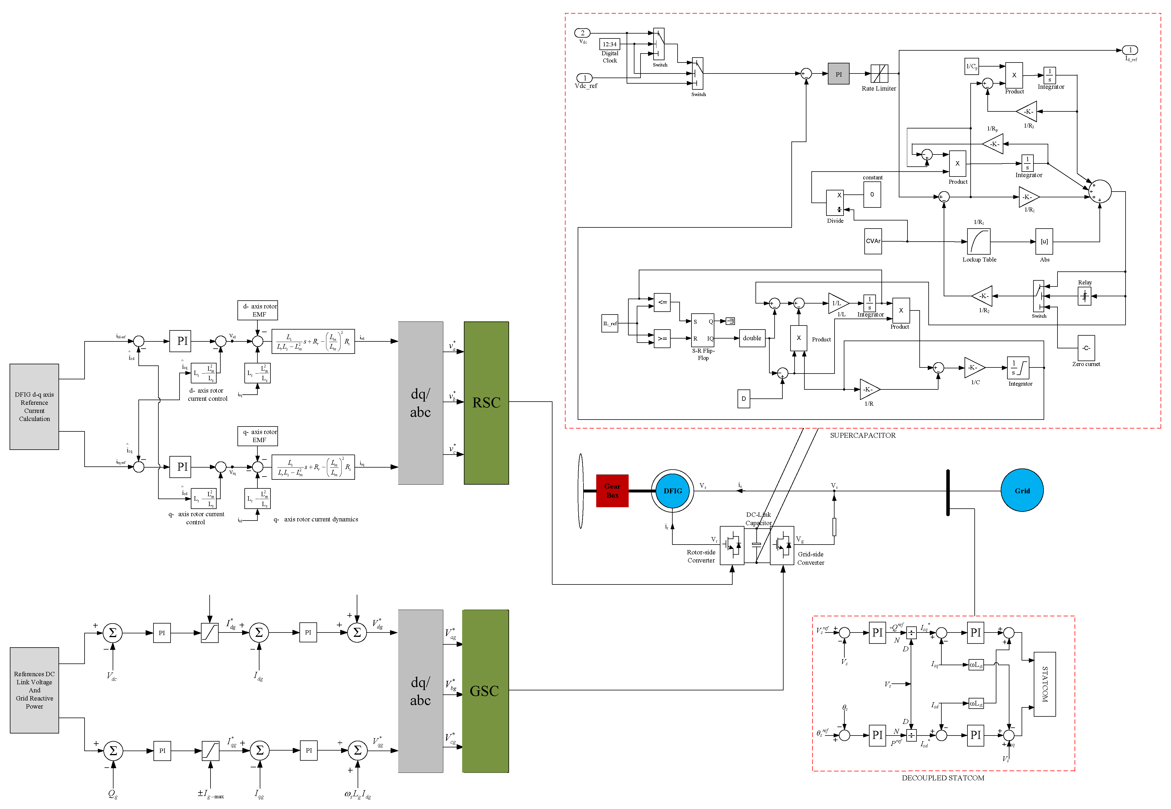
The coordinate control model obtained by the development of the DFIG stator–rotor emf, lookup-table-based supercapacitor, and decoupled STATCOM models is shown in Figure 5.
This coordinate control was developed to provide stator–rotor dynamics to stabilize the system quickly during balanced and unbalanced faults. In contrast, the supercapacitor and STATCOM models were developed to provide active–reactive power control in the system. For this, the emf voltage source was used primarily in both stator and rotor circuits. The stator improves the performance of the emf simulation operation; furthermore, with the rotor emf, overvoltages and overcurrents are damped in a short time. The supercapacitor model was used to provide active power control in the DFIG. Here, the supercapacitor model was improved using the lookup table depending on the voltage–capacity relationship. The voltage value increases in the capacity–voltage curve of the supercapacitor, and the capacity value increases. Depending on this curve, a capacity selection process suitable for 1200 V DC voltage was performed in the simulation system. As the voltage produced in the supercapacitor was to be equal to the DC voltage value, a buck-boost converter circuit was needed. In the buck-boost circuit, a resistor, coil, and capacitor were used. The resistance value was determined in the simulation study depending on the charge state of the supercapacitor. The output voltage in the buck-boost circuit was equal to the 1200 V DC voltage. Since the three-phase and two-phase fault periods were 0.58–0.68, 0.58–0.73, and 0.58–0.78 s, the supercapacitor was charged in 0.5 s in the simulation study. The supercapacitor was switched on and off with a switching element between 0.5 and 5 s. The STATCOM was used for reactive power control in the DFIG system. With decoupled control, STATCOM’s modulation index and the bus voltage angle effectively reduced the transient effect. Moreover, active–reactive power flow control between the line and bus with the decoupled STATCOM was successfully performed in this study.

6. Simulation Study

This study was carried out in MATLAB/SIMULINK environment. The test system modeled a 2.3 MW grid-connected DFIG-based wind turbine, as shown in Figure 6.
DFIG output voltage was 0.69 kV. For the 34.5 kV system connection of the DFIG, a 2.6 MVA 0.69 kV Y/34.5 kV Δ transformer was used. For this study, the saturation of the transformers was disregarded. The distance between the DFIG and the 34.5 kV grid was 1 km. In this study, the wind speed for the wind turbine was considered to be 8 m/s. The short circuit power of the grid was taken as 2500 MVA and the X/R ratio as 7. The STATCOM power selected for this system was 10 MVA. In the buck-boost converter circuit of the supercapacitor, a resistance of 160 ohm, an inductance of 1 mH, and a capacitor value of 0.5 µF were selected [33]. In this test system, three-phase and two-phase faults occurred in the 34.5 kV bus. Both fault analyses included different fault time intervals, which were selected as 0.58–0.68, 0.58–0.73, and 0.58–0.78 s. The basic parameter list used in the wind turbine is given in Table 1.

7. Simulation Study Results

In addition to the development of stator and rotor dynamic models in a DFIG, the use of a supercapacitor and STATCOM provided coordinate control of the system during balanced and unbalanced faults. First, three-phase faults occurred in the 34.5 kV bus. The three-phase faults occurred for 0.58–0.68, 0.58–0.73, and 0.58–0.78 s. The changes in the 34.5 kV bus voltage and DFIG parameters during the three-phase faults lasting for the three different periods were investigated.
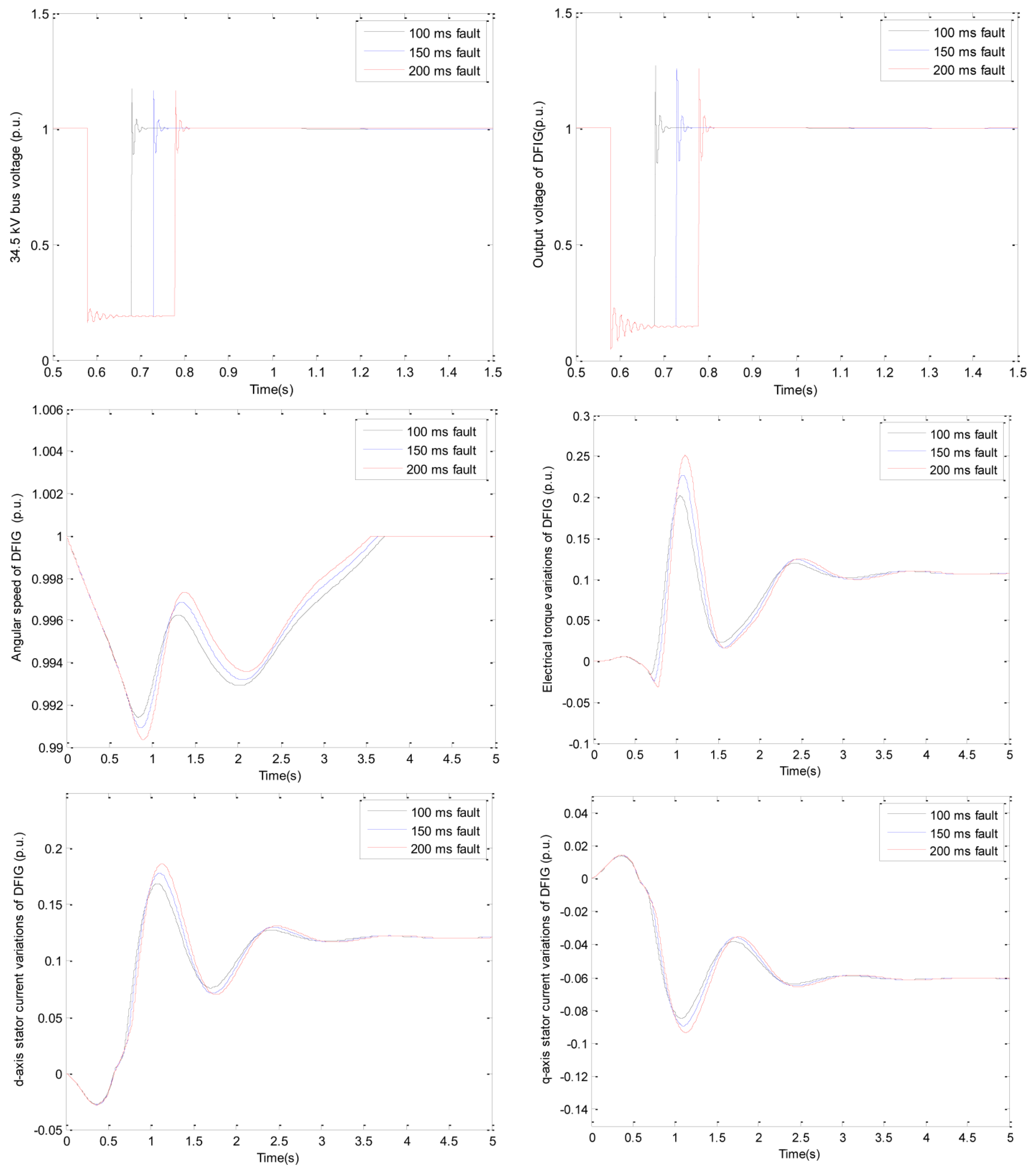
The simulation results of the conventional and developed coordinate control models were obtained separately. The comparisons of the results for the three-phase faults are shown in Figure 7 and Figure 8.
As can be seen in Figure 7, the conventional DFIG model operation was unstable during the three-phase faults lasting for different periods. However, Figure 8 shows that the developed coordinate control model stabilized the system in a short time. In both cases, the oscillations that occurred during the fault interval of 200 ms were greater than during the 100 ms or 150 ms fault times. With the conventional DFIG model used during the three-phase faults, the 34.5 kV bus voltage had become stable in 0.71, 0.76, and 0.81 s, respectively; the DFIG output voltage in 0.72, 0.77, and 0.82 s; the angular speed in 5.8, 6 and 6.5 s; the electrical torque in 5.8, 6 and 6.5 s; and the d-q axis stator current variations in 6.5, 6.7 and 7.2 s. The maximum and minimum oscillation interval values of the parameters used in the system were found to be 0–1.15 p.u. for the 34.5 kV bus voltage; 0.1–1.3 p.u. for the DFIG output voltage; 1–1.45 p.u. for the angular speed; −3.8–6 p.u. for the electrical torque; −2.5–2.8 p.u. for the d-axis stator current variations; and −1.3–1.2 p.u. for the q-axis stator current variations. It was determined that the system had become stable in a short time in the developed model during the three-phase faults lasting for three different periods. With the developed model, the results showed that the 34.5 kV bus voltage had become stable in 0.7, 0.75, and 0.8 s, respectively; the DFIG output voltage in 0.71, 0.76, and 0.81 s; the angular speed in 3.5, 3.6, and 3.7 s; the electrical torque in 3.6, 3.7, and 3.8 s; and the d-q axis stator current variations in 3.9, 4, and 4.1 s. The maximum and minimum oscillation interval values of the parameters used in the system were revealed as 0–1.15 p.u. for the 34.5 kV bus voltage; 0.1–1.25 p.u. for the DFIG output voltage; 0.99–1 p.u. for the angular speed; −0.03–0.25 p.u. for the electrical torque; −0.025–0.18 p.u. for the d-axis stator current variations; and −0.01–0.01 p.u. for the q-axis stator current variations.
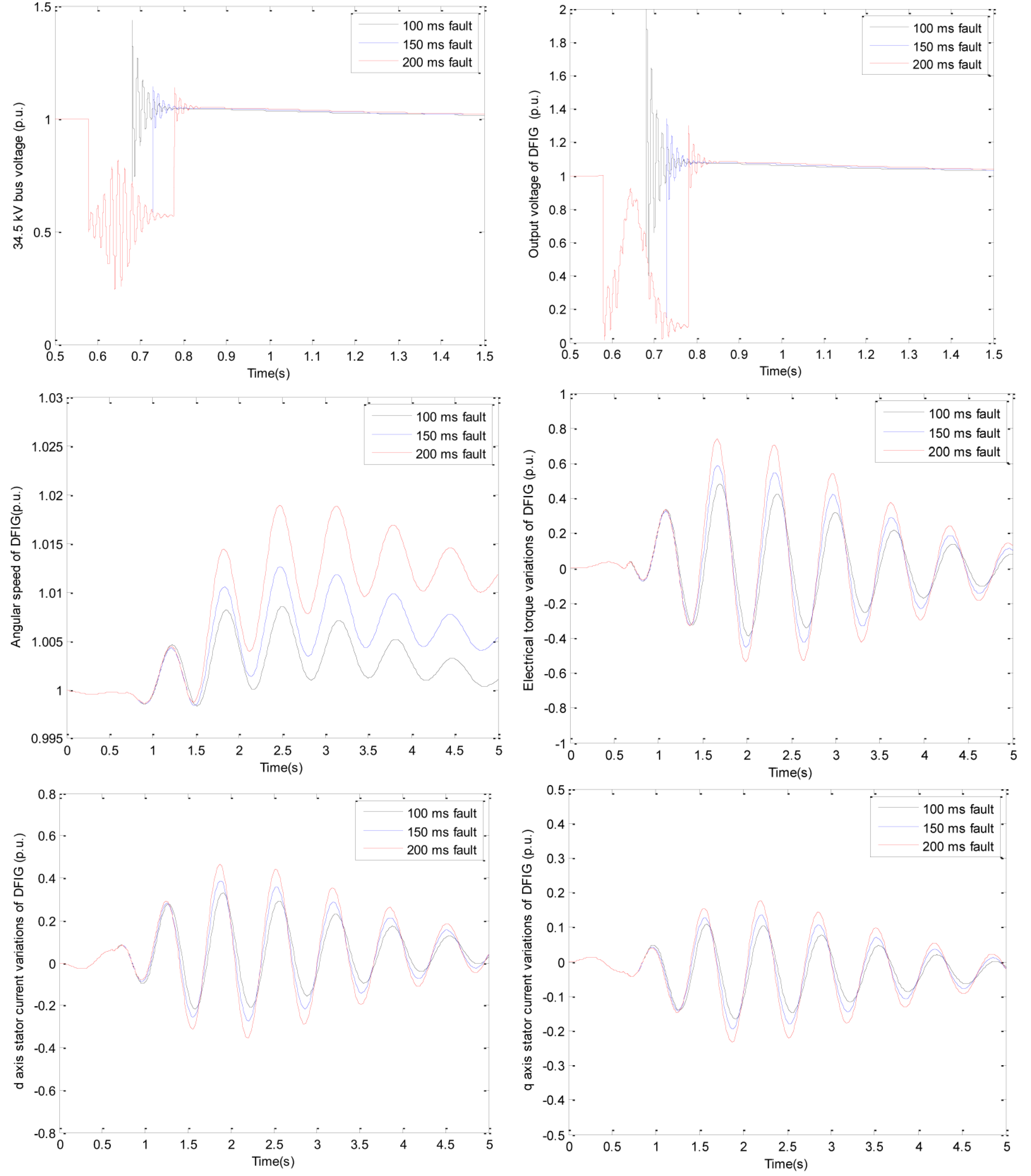
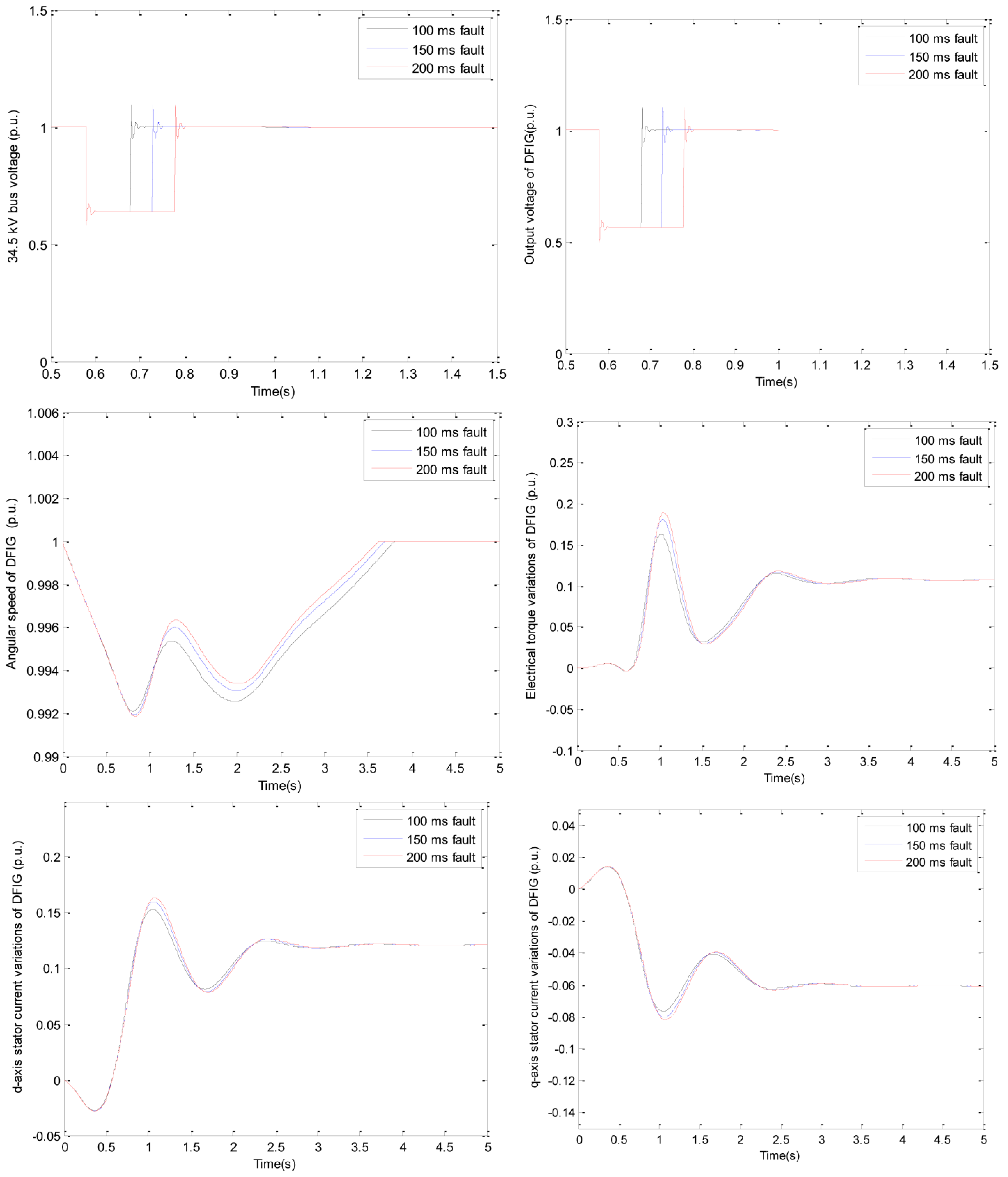
In the simulation study, two-phase faults were selected from unbalanced faults. In this scenario, as in the first analysis approach, two-phase faults lasting for three different time periods were examined. In the second analysis, fault times were selected as 0.58–0.68, 0.58–0.73, and 0.58–0.78 s. The two-phase faults results that occurred in the 34.5 kV bus are given in Figure 9 and Figure 10.
System oscillations decreased when the two-phase faults occurred in the system (Figure 9) compared to those occurring during the three-phase faults. In both the conventional and the developed models, the oscillations occurring during the two-phase fault interval of 200 ms were greater than for the 100 ms or 150 ms intervals. In the two-phase faults occurring for 0.58–0.68, 0.58–0,73, and 0.58–0.78 s, the 34.5 kV bus voltage had become stable in 0.75, 0.77, and 0.8 s, respectively; the DFIG output voltage in 0.78, 0.8, and 0.83 s; the angular speed in 6.4, 6.7, and 7 s; the electrical torque in 6.5, 6.8, and 7.1 s; and the d-q axis stator current variations in 6.2, 6.5, and 6.8 s. The maximum and minimum oscillation interval values of the parameters used in the system were 0.25–1.45 p.u. for the 34.5 kV bus voltage; 0–2 p.u. for the DFIG output voltage; 1–1.02 p.u. for the angular speed; −0.58–0.76 p.u. for the electrical torque; −0.38–0.44 p.u. for the d-axis stator current variations; and −0.22–0.19 p.u. for the q-axis stator current variations. For the two-phase faults lasting for intervals of 0.58–0.68, 0.58–0.73, and 0.58–0.78 s, it was determined that the system had become stable quickly in the developed model using the developed stator–rotor emf, lookup-table-based supercapacitor and decoupled STATCOM models. The results given in Figure 10 show that the 34.5 kV bus voltage had become stable in 0.69, 0.74, and 0.79 s, respectively; DFIG output voltage in 0.7, 0.75, and 0.8 s; angular speed in 3.6, 3.7, and 3.8 s; electrical torque in 3.3, 3.4, and 3.5 s; and d-q axis stator current variations in 3.3, 3.4, and 3.5 s. The maximum and minimum oscillation interval values of the parameters used in the system were 0.63–1.08 p.u. for the 34.5 kV bus voltage; 0.6–1.1 p.u. for the DFIG output voltage; 0.992–1 p.u. for the angular speed; 0–0.18 p.u. for the electrical torque; −0.25–0.166 p.u. for the d-axis stator current variations; and −0.082–0.016 p.u. for the q-axis stator current variations.

8. Conclusions

Various theoretical studies for DFIG balanced and unbalanced faults have aimed to quickly stabilize the system and eliminate oscillations. In this study, a stator–rotor emf model developed in the RSC circuit of a DFIG, a lookup-table-based supercapacitor model developed in the GSC circuit of the DFIG, and a decoupled STATCOM model in connection point with a grid of the DFIG-based wind turbine were used for the analysis of three-phase and two-phase faults lasting for different periods. The results obtained in the developed models are given below.
  • With the development of the stator dynamic model, the performance of the simulation study increased, while the system oscillations and the time to reach the system’s stability decreased with the rotor dynamic model.
  • With the supercapacitor model, which was developed based on the lookup table, both smooth power output and appropriate capacity for the appropriate voltage were obtained.
  • Using the decoupled STATCOM, it was observed that it compensates the bus voltages depending on the reactive power in the transient stability analysis.
The model developed in this study was found to yield good and effective results in terms of stability and damping of three-phase and two-phase faults lasting for different time periods. The stator–rotor dynamic model developed in this study can be applied to generators used in different wind turbines, and it will be beneficial for future studies to develop different models in supercapacitors and STATCOM.

Funding

This research received no external funding.

Institutional Review Board Statement

Not applicable.

Informed Consent Statement

Not applicable.

Data Availability Statement

Not applicable.

Conflicts of Interest

The authors declare no conflict of interest.

References

  1. Ling, Y.; Cai, X.; Wang, N. Rotor current transient analysis of DFIG-based wind turbines during symmetrical voltage faults. Energy Convers. Manag. 2013, 76, 910–917. [Google Scholar] [CrossRef]
  2. Ling, Y.; Cai, X. Rotor current dynamics of doubly fed induction generators during grid voltage dip and rise. Int. J. Electr. Power Energy Syst. 2013, 44, 17–24. [Google Scholar] [CrossRef]
  3. Mohammadi, J.; Afsharnia, S.; Ebrahimzadeh, E.; Blaabjerg, F. An enhanced LVRT scheme for DFIG-based WECSs under both balanced and unbalanced grid voltage sags. Electr. Power Compon. Syst. 2017, 45, 1242–1252. [Google Scholar] [CrossRef]
  4. Mohammadi, J.; Afsharnia, S.; Vaez-Zadeh, S. Efficient fault-ride-through control strategy of DFIG-based wind turbines during the grid faults. Energy Convers. Manag. 2014, 78, 88–95. [Google Scholar] [CrossRef]
  5. Saad, N.H.; Sattar, A.A.; Mansour, A.E.A.M. Low voltage ride through of doubly-fed induction generator connected to the grid using sliding mode control strategy. Renew. Energy 2015, 80, 583–594. [Google Scholar] [CrossRef]
  6. Benbouzid, M.; Beltran, B.; Amirat, Y.; Yao, G.; Han, J.; Mangel, H. Second-order sliding mode control for DFIG-based wind turbines fault ride-through capability enhancement. ISA Trans. 2014, 53, 827–833. [Google Scholar] [CrossRef] [Green Version]
  7. Xiao, S.; Geng, H.; Zhou, H.; Yang, G. Analysis of the control limit for rotor-side converter of doubly fed induction generator-based wind energy conversion system under various voltage dips. IET Renew. Power Gener. 2013, 7, 71–81. [Google Scholar] [CrossRef]
  8. Xiao, S.; Yang, G.; Zhou, H.; Geng, H. An LVRT control strategy based on flux linkage tracking for DFIG-based WECS. IEEE Trans. Ind. Electron. 2013, 60, 2820–2832. [Google Scholar] [CrossRef]
  9. Zhu, R.; Chen, Z.; Wu, X.; Deng, F. Virtual damping flux-based LVRT control for DFIG-based wind turbine. IEEE Trans. Energy Convers. 2015, 30, 714–725. [Google Scholar] [CrossRef]
  10. Kyaw, M.M.; Ramachandaramurthy, V.K. Fault ride through and voltage regulation for grid connected wind turbine. Renew. Energy 2011, 36, 206–215. [Google Scholar] [CrossRef]
  11. Lima, F.K.; Luna, A.; Rodriguez, P.; Watanabe, E.H.; Blaabjerg, F. Rotor voltage dynamics in the doubly fed induction generator during grid faults. IEEE Trans. Power Electron. 2010, 25, 118–130. [Google Scholar] [CrossRef] [Green Version]
  12. Döşoğlu, M.K.; Güvenç, U.; Sönmez, Y.; Yılmaz, C. Enhancement of demagnetization control for low-voltage ride-through capability in DFIG-based wind farm. Electr. Eng. 2018, 100, 491–498. [Google Scholar] [CrossRef]
  13. Geng, H.; Liu, C.; Yang, G. LVRT capability of DFIG-based WECS under asymmetrical grid fault condition. IEEE Trans. Ind. Electron. 2013, 60, 2495–2509. [Google Scholar] [CrossRef]
  14. Zhou, L.; Liu, J.; Zhou, S. Improved demagnetization control of a doubly-fed induction generator under balanced grid fault. IEEE Trans. Power Electron. 2014, 30, 6695–6705. [Google Scholar] [CrossRef]
  15. Döşoğlu, M.K. A new approach for low voltage ride through capability in DFIG based wind farm. Int. J. Electr. Power Energy Syst. 2016, 83, 251–258. [Google Scholar] [CrossRef]
  16. Hu, S.; Lin, X.; Kang, Y.; Zou, X. An improved low-voltage ride-through control strategy of doubly fed induction generator during grid faults. IEEE Trans. Power Electron. 2011, 26, 3653–3665. [Google Scholar] [CrossRef]
  17. Vidal, J.; Abad, G.; Arza, J.; Aurtenechea, S. Single-phase DC crowbar topologies for low voltage ride through fulfillment of high-power doubly fed induction generator-based wind turbines. IEEE Trans. Energy Convers. 2013, 28, 768–781. [Google Scholar] [CrossRef]
  18. Peng, L.; Francois, B.; Li, Y. Improved crowbar control strategy of DFIG based wind turbines for grid fault ride-through. In Proceedings of the 2009 Twenty-Fourth Annual IEEE Applied Power Electronics Conference and Exposition, Washington, DC, USA, 15–19 February 2009. [Google Scholar]
  19. Justo, J.J.; Mwasilu, F.; Jung, J.W. Enhanced crowbarless FRT strategy for DFIG based wind turbines under three-phase voltage dip. Electr. Power Syst. Res. 2017, 142, 215–226. [Google Scholar] [CrossRef]
  20. Long, T.; Shao, S.; Malliband, P.; Abdi, E.; McMahon, R.A. Crowbarless fault ride-through of the brushless doubly fed induction generator in a wind turbine under symmetrical voltage dips. IEEE Trans. Ind. Electron. 2012, 60, 2833–2841. [Google Scholar] [CrossRef]
  21. Uphues, A.; Notzold, K.; Wegener, R.; Soter, S. DFIG’s virtual resistance demagnetization for crowbar less LVRT. In Proceedings of the 2017 IEEE 12th International Conference on Power Electronics and Drive Systems (PEDS), Honolulu, HI, USA, 12–15 December 2017. [Google Scholar]
  22. Mohseni, M.; Masoum, M.A.; Islam, S.M. Low and high voltage ride-through of DFIG wind turbines using hybrid current controlled converters. Electr. Power Syst. Res. 2011, 81, 1456–1465. [Google Scholar] [CrossRef]
  23. Dai, J.; Xu, D.; Wu, B.; Zargari, N.R. Unified DC-link current control for low-voltage ride-through in current-source-converter-based wind energy conversion systems. IEEE Trans. Power Electron. 2011, 26, 288–297. [Google Scholar]
  24. Yang, L.; Xu, Z.; Ostergaard, J.; Dong, Z.Y.; Wong, K.P. Advanced control strategy of DFIG wind turbines for power system fault ride through. IEEE Trans. Power Syst. 2012, 27, 713–722. [Google Scholar] [CrossRef] [Green Version]
  25. Abbey, C.; Joos, G. Supercapacitor energy storage for wind energy applications. IEEE Trans. Ind. Appl. 2007, 43, 769–776. [Google Scholar] [CrossRef]
  26. Döşoğlu, M.K.; Arsoy, A.B. Transient modeling and analysis of a DFIG based wind farm with supercapacitor energy storage. Int. J. Electr. Power Energy Syst. 2016, 78, 414–421. [Google Scholar] [CrossRef]
  27. Sarrias-Mena, R.; Fernández-Ramírez, L.M.; García-Vázquez, C.A.; Jurado, F. Improving grid integration of wind turbines by using secondary batteries. Renew. Sustain. Energy Rev. 2014, 34, 194–207. [Google Scholar] [CrossRef]
  28. Zheng, Z.; Yang, G.; Geng, H. Coordinated control of a doubly-fed induction generator-based wind farm and a static synchronous compensator for low voltage ride-through grid code compliance during asymmetrical grid faults. Energies 2013, 6, 4660–4681. [Google Scholar] [CrossRef] [Green Version]
  29. Ananth, D.V.N.; Kumar, G.N. Fault ride-through enhancement using an enhanced field oriented control technique for converters of grid connected DFIG and STATCOM for different types of faults. ISA Trans. 2016, 62, 2–18. [Google Scholar] [CrossRef]
  30. Kumar, N.S.; Gokulakrishnan, J. Impact of FACTS controllers on the stability of power systems connected with doubly fed induction generators. Int. J. Electr. Power Energy Syst. 2011, 33, 1172–1184. [Google Scholar] [CrossRef]
  31. Ekanayake, J.B.; Holdsworth, L.; Jenkins, N. Comparison of 5th order and 3rd order machine models for doubly fed induction generator (DFIG) wind turbines. Electr. Power Syst. Res. 2003, 67, 207–215. [Google Scholar] [CrossRef]
  32. Kundur, P.; Balu, N.J.; Lauby, M.G. Power System Stability and Control; McGraw-hill: New York, NY, USA, 1994. [Google Scholar]
  33. Krause, P.C.; Wasynczuk, O.; Sudhoff, S.D.; Pekarek, S. Analysis of Electric Machinery and Drive Systems; IEEE Press: New York, NY, USA, 2002. [Google Scholar]
  34. Johansson, P.; Andersson, B. Comparison of Simulation Programs for Supercapacitor Modeling. Master’s Thesis, Chalmers University of Technology, Göteborg, Sweden, 2008. [Google Scholar]
  35. Gaiceanu, M. MATLAB/simulink-Based Grid Power Inverter for Renewable Energy Sources Integration, In MATLAB—A Fundamental Tool for Scientific Computing and Engineering Applications; Katsikis, V.N., Ed.; IntechOpen: London, UK, 2012; Volume 3. [Google Scholar]
  36. Rahim, A.H.M.A.; Alam, M.A. STATCOM-Supercapacitor Control for Low Voltage Performance Improvement of Wind Generation Systems. Arab. J. Sci. Eng. 2013, 38, 3133–3143. [Google Scholar] [CrossRef]
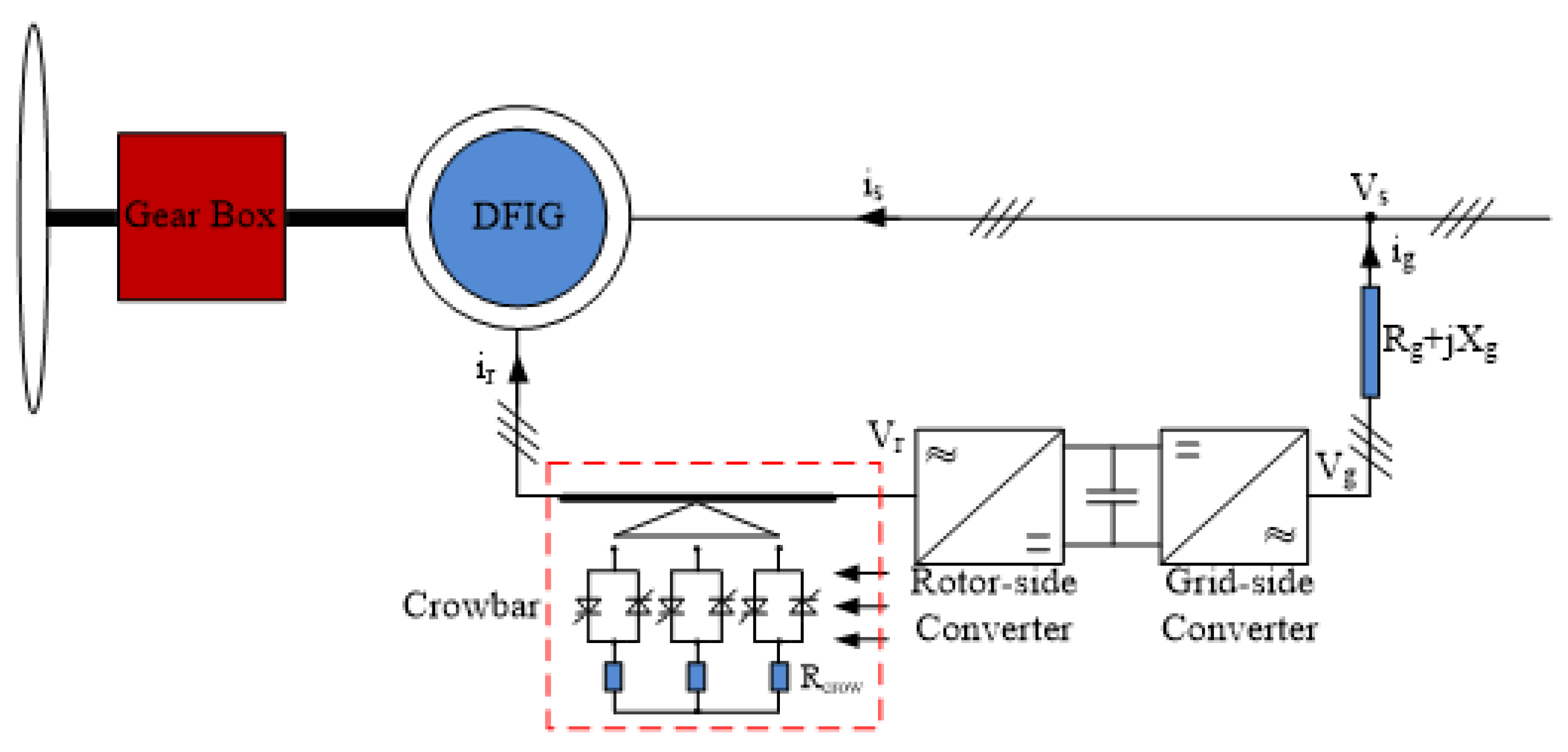
Figure 1. Circuit model of DFIG.
Sustainability 15 02529 g001
Figure 2. Supercapacitor circuit in DFIG.
Sustainability 15 02529 g002
Figure 3. DFIG Basic Circuit Model of the Supercapacitor.
Sustainability 15 02529 g003
Figure 4. STATCOM Equivalent Circuit Modeling.
Sustainability 15 02529 g004
Figure 5. DFIG Stator–Rotor EMF, Lookup-Table-Based Supercapacitor and Decoupled STATCOM Modeling.
Sustainability 15 02529 g005
Figure 6. Test System.
Sustainability 15 02529 g006
Figure 7. Conventional DFIG Model Results During Three-Phase Faults.
Sustainability 15 02529 g007
Figure 8. Developed DFIG Model Results During Three-Phase Faults.
Sustainability 15 02529 g008
Figure 9. Conventional DFIG Model Results During Two-Phase Faults.
Sustainability 15 02529 g009
Figure 10. Developed DFIG Model Results During Two-Phase Faults.
Sustainability 15 02529 g010
Table 1. The basic parameter list used in the wind turbine.
ParametersValue
Power2.3 MW
Constant wind speed8 m/s
Coefficient at rated wind speed0.73
Operating rotational speed range6–9.6 rpm
Maximum pitch angle45 deg
Disclaimer/Publisher’s Note: The statements, opinions and data contained in all publications are solely those of the individual author(s) and contributor(s) and not of MDPI and/or the editor(s). MDPI and/or the editor(s) disclaim responsibility for any injury to people or property resulting from any ideas, methods, instructions or products referred to in the content.