Article

Battery Power Control Strategy for Intermittent Renewable Energy Integrated Modular Multilevel Converter-Based High-Voltage Direct Current Network

by
Md Ismail Hossain
1,
Md Shafiullah
1 and
Mohammad A. Abido
1,2,3,*
1
Interdisciplinary Research Center for Renewable Energy and Power Systems (IRC-REPS), King Fahd University of Petroleum & Minerals, Dhahran 31261, Saudi Arabia
2
K.A. CARE, Energy Research & Innovation Center, Dhahran 31261, Saudi Arabia
3
Electrical Engineering Department, King Fahd University of Petroleum & Minerals, Dhahran 31261, Saudi Arabia
*
Author to whom correspondence should be addressed.
Sustainability 2023, 15(3), 2626; https://doi.org/10.3390/su15032626
Submission received: 17 October 2022 / Revised: 26 January 2023 / Accepted: 29 January 2023 / Published: 1 February 2023
(This article belongs to the Special Issue Smart Grid Technologies and Renewable Energy Applications)

Abstract

:
Modular multilevel converters (MMC) play a dominant role in integrating remotely located renewable energy resources (RER) over the high-voltage direct current (HVDC) transmission network. The fault ride-through capabilities of the MMC-HVDC network during low-voltage faults and the power fluctuation due to RER intermittency are the major obstacles to the effective integration of renewable energy. In response, this article proposes a local voltage-based combined battery energy control scheme for a PV-wind-battery connected MMC-HVDC system to regulate the HVDC-link voltage during low-voltage faults at the point of common coupling of alternating current grids and to reduce the intermittent RER power fluctuation. The proposed technique removes the dynamic braking resistor from the HVDC-link and smoothly integrates the RER without active power reduction of renewable energy under low-voltage faults. Symmetrical and unsymmetrical low-voltage faults have been conducted to validate the effectiveness of the proposed control scheme for the battery in mitigating surplus energy in the HVDC-link. Additionally, wind speed, solar radiation, and temperature have been changed to confirm the improved performance of the battery energy management system. The complete systems have been simulated and tested in a real-time digital simulator (RTDS) and using dSPACE-based controller hardware in a loop setup.

1. Introduction

The MMC-HVDC connection has been identified as one of the most promising technologies for integrating the RER because of its scalability, modularity, and compact footprint [1,2,3]. The AC grid can receive stability support from the MMC-HVDC-connected RER, including frequency regulation [4] and dynamic voltage control [5]. However, the FRT capabilities of the MMC-HVDC network continue to be a significant obstacle. When a grid fault occurs, the active power produced by the onshore MMC is abruptly reduced, making it impossible for wind farms to transmit their generated power to the grid entirely. Due to the aforementioned power imbalance, the DC-link voltage increases quickly as the relevant capacitors are charged. The installation of dynamic brake resistors and quick power reduction of wind farms (WF) are some current practices to prevent overvoltage in the DC-link. The fault is isolated to improve the voltage profile and power transmission capacity of the onshore grid, and the DBR is used to dissipate the excess power [6,7,8,9,10,11]. The benefit of these techniques is that grid faults do not impact WFs, but they require additional hardware, including breakers, braking resistors, and series transformers. Rapid active power reduction can also be accomplished through the utilization of communication-based de-loading control [12], voltage droop control [13,14,15,16,17,18,19,20,21,22,23,24,25,26,27], and frequency modulation [28,29,30]. The DC-link communication channels with wind turbines (WT) eliminate the need for additional offshore converter control, but they also cause reliability and latency issues.
As an alternative, the offshore grid frequency is raised in proportion to the DC voltage variation to perform frequency modulation control. Unfortunately, the delayed active power response of the WF due to poor DF/DT tolerant capability severely restricts this technique. Voltage drop management enables a quick reduction in WF active power to simplify the FRT of coupled offshore MMC-HVDC-connected wind farms. A real power current reduction control is proposed for WTs to contribute to the fault ride-through requirements of the HVDC network, along with a small voltage droop control solution in [13,14,15,16,17,18]. However, this could lead to significant DC overvoltage because of a voltage signal processing delay in filter and bandwidth constraints in the current signal management of WTs. To keep the DC voltage at the required level, the offshore converter quickly reduces the offshore grid voltage to zero in [19,20,21,22,23,24,25,26,27]. The phase lock loop (PLL)-based wind turbine converters may experience synchronization problems using this technology, which does not require any changes to the WT control [31,32,33]. Two-stage droop control is proposed to enhance FRT and post-fault recovery for MMC-HVDC-connected offshore wind farms [34]. However, a simplified current source is used to represent the wind turbine, which ignores the turbine inertia that introduces a delay to the rapid power reduction. Similarly, active power reduction-based DC-link overvoltage control also encounters a delay due to the large inertia of the wind turbine, which prevents rapid change in active power.
In addition to the mentioned control strategy, the RER is highly intermittent and finds it challenging to match users’ demands. Within this context, energy storage systems (ESS), especially battery ESS, have been recognized as a key technology to address such intermittency and facilitate effective penetration of the RER into electricity grids. The demand for light and high-capacity energy storage is rising in many different applications. One such application is the large-scale ESS with different types of renewable generation. To mitigate or smooth out the fast transients due to uncontrollable circumstance changes such as solar radiation, temperature, and wind speed change, more energy storage systems are now deployed along with these renewable generation stations, thus raising the acceptability of such methods of electricity generation to utility companies. Due to its light weight and high energy density, the lithium-ion battery is taking up a large portion of actual storage devices’ role in grid application [35,36,37]. A flywheel energy storage device can rapidly change ample power that can be utilized to control additional energy during a low-voltage disturbance. In a flywheel ESS-based FRT support, excess energy is collected as kinetic energy depending on the rotating speed and mass [38,39,40,41,42,43,44,45,46]. Flywheel energy storage is connected with an HVDC-link through a separate MMC to mitigate wind energy fluctuation [41]. Consequently, it requires similar expensive infrastructure to the grid-connected converter. In addition, a small-scale prototype has been developed to verify the proposed control scheme’s efficacy. In contrast, non-real-time simulation software employed an average model to obtain results. In contrast, the high-power density super-capacitor is a short-duration power source with a fast dynamic response [46,47,48,49,50]. With the assistance of the voltage source converter (VSC)-based HVDC-link during an AC side fault, it offers a similar potential for fault riding [39,51]. Both technologies could be utilized for power smoothing during normal conditions and FRT improvement. Both technologies, however, are costly and suffer from significant energy loss that limits their capability in practical implementation.
The battery is the second highest globally installed ESS capacity after pumped hydro storage [52]. The battery energy storage system (BESS) has a high energy density and can maintain a charge for a prolonged period. As a result, several utilities are turning to BESS for power leveling, voltage and frequency management, and FRT improvement. The BESS is lightweight, and has a high energy density, high power density, quick response time, and high cycle efficiency [45,53]. Additionally, over the passage of time, the cost of battery energy storage systems (BESS) has decreased significantly [54]. However, the BESS size determines how much time it will take to deliver energy to offset the energy deficiency caused by the RER intermittency. The work reported in [55,56] connected the battery with the HVDC-link and onshore AC side through MMC to mitigate wind energy fluctuation. As a result, it requires expensive infrastructure similar to that of the grid-connected converter. In addition, non-real-time simulation software employing an average model was used to perform the simulation. In adddition, AC side faults have not been considered. According to the article [57,58], there are three configurations of battery-connected MMC. A cascaded centralized battery string is placed on the DC-link to provide bidirectional active power [59]. However, this increases loss, and undergoes high-voltage stress and no galvanic isolation. In a cascaded converter with a BESS, the battery forms the DC source with an individual converter, and the HVDC-link forms with a cascaded converter [60]. The literature [61,62,63,64,65] has discussed MMC with an integrated battery connected with a submodule. However, this requires a bidirectional DC-DC converter. Furthermore, the simulation has not considered the complete system with individual MMC submodules and the distributed battery. One submodule with a battery was used to scale and present all submodule dynamics.
Considering the aforementioned notes and challenges, this research proposes a novel local voltage-based battery energy control scheme to control the surplus power in the HVDC-link during the AC side low-voltage faults. In addition, it combines the control of the transient performance enhancement to deal with the intermittent nature of the RER. In summary, the major contributions of this research are:
  • A local voltage-based combined energy control approach for the battery (a) to regulate the HVDC-link voltage during the low-voltage faults at the PCC of AC grids, and (b) to address intermittency caused by the renewable energy generation fluctuation.
  • Simulation and testing of the complete systems in a real-time digital simulator (RTDS) and dSPACE-based controller hardware in the loop (CHIL), with detailed converter models.
The rest of the article is structured as follows. Section 2 presents the framework of the controller employed in the PV-wind-battery-based renewable energy integrated MMC-HVDC system. Section 3 demonstrates the proposed control strategy for the battery energy management system to control the surplus power in the HVDC-link and smooth out the transience caused by solar and wind energy variation. Section 4 provides detailed simulation results for the HVDC-link voltage regulation during low-voltage AC side transient faults and the enhancement of transient performance due to RER intermittency. Finally, Section 5 draws conclusions and provides future research directions.

2. Modeling and Controller Design

The system comprises of PV and wind farms with a BESS, as depicted in Figure 1. The MMC1 manages the HVDC-link voltage, whereas the MMC2 connects the AC grid with the PV-wind-battery system. Scaling the output (Icom) from one unit of energy storage and renewable energy through a controlled current source and multiplier (M10) increases the system’s capacity.

2.1. Battery Modeling and Sizing

Figure 2 shows the equivalent electrical circuit for the Min/Rincón-Mora lithium-ion battery model [66]. In the equivalent circuit, the components (RTransient_S and CTransient_S) determine the short-term transience of the battery; in contrast, the components (RTransient_L and CTransient_L) refer to the long-term transience of the battery. As employed in the model, two RC time constants are the best trade-off between the model’s accuracy and complexity. The non-linear circuit parameters used in the equivalent model are functions of the state of charge (SOC). Therefore, single variable functions are used to describe those parameters’ behavior mathematically.
The following relation defines the state of charge of the battery:
S O C = S O C 0 1 3600 A H 0 t I B a t t e r y d t
where, S O C 0 is the initial state of charge, AH is the nominal ampere-hour of the battery, and I B a t t e r y is the battery charging/discharging current. Equation (1) is known as coulomb counting method or ampere-hour counting and current integration technique for calculating the SOC. This method employs battery current readings mathematically integrated over the usage period to calculate SOC values. The coulomb counting method then calculates the remaining capacity simply by accumulating the charge transferred in or out of the battery. The accuracy of this method resorts primarily to a precise measurement of the battery current and accurate estimation of the initial SOC. With a pre-known capacity, which might be memorized or initially estimated by the operating conditions, the SOC of a battery can be calculated by integrating the charging and discharging currents over the operating periods. The accuracy or tuning of coulomb counting method is improved by adding the open circuit voltage method. Besides the coulomb counting method, a smart battery management system can provide information on the state of charge of the battery. The battery is rated for 4 MW for 15 min, which implies that if a 4 MW steady power injection is maintained for 15 min, the battery will be fully charged. The battery will also be completely discharged after 15 min of draining at a 4 MW rate. Therefore, the energy density = Power capacity × discharge time = 4 MW × 0.25 h = 1 MWh.
The EssProTM Grid from ABB (Switzerland), SIESTORAGE from Siemens (Germany), MaxSineTM eStorage from Alstom (France), AEG BESS from AEG Power Solutions (Netherlands), Battery Energy Storage System from Toshiba (Japan), GE Energy Storage from GE (US), Power Storage Solution from Bosch (Germany), Advancion® 4 Energy Storage from AES (US), and the Eos Aurora® 1000 | 4000 from Eos (US) are some of the commercially available BESS solutions [56].
The EssProTM Grid, according to ABB, can be used for a variety of purposes, including frequency regulation, spinning reserves, smoothing out rapid voltage and power fluctuations brought on by intermittent renewable energy sources, peak shaving and load leveling, improving power quality, acting as an uninterruptible power supply (UPS), and assisting in maintaining grid voltage by injecting or absorbing reactive power. The EssProTM Grid BESS is battery technology independent, which means that based on the application and requirements, the system may be adjusted for different types of batteries. Lithium-ion, sodium–sulfur, nickel–cadmium, lead–acid, or flow batteries are all acceptable types of batteries. The maximum DC voltage of the EssProTM Grid is 1.2 kV, and the output active power ranges from 100 kW up to 30 MW, with a nominal energy capacity from 200 kWh up to 7.2 MWh. More information regarding the EssProTM Grid BESS can be found in the technical brochure on ABB’s website [67]. We require four units of 1 MW discharge power capacity EssProTM Grid containers connected in parallel. The technical specifications for one EssProTM Grid container are presented in Table 1.

2.2. Solar and Wind Energy Grid Integration

The main purpose of converter control for solar and wind energy is integration with an MMC2-supported AC grid. The maximum output power of the photovoltaic panel varies with solar radiation and temperature variation, as is known from the power–voltage (P–V) characteristics curve. Therefore, the PV side converter adjusts the DC-link voltage to extract maximum power from the PV system under any operating condition (temperature and solar irradiation) employing a modified incremental conductance method. The grid integration of solar energy can be found in more detail in References [9,68,69,70]. Similarly, the optimal point of turbine mechanical energy varies with wind speed, as shown in the wind turbine power–generator speed curve. The rotor side converter (RSC) controls the optimal electromagnetic torque set by the optimal point of wind energy which employs field-oriented control. Therefore, the setpoint for electromagnetic torque is varied according to the wind speed to extract optimum wind energy. The detailed design for DFIG-based wind energy grid integration can be found in [9,71].

2.3. Modular Multilevel Converter Control

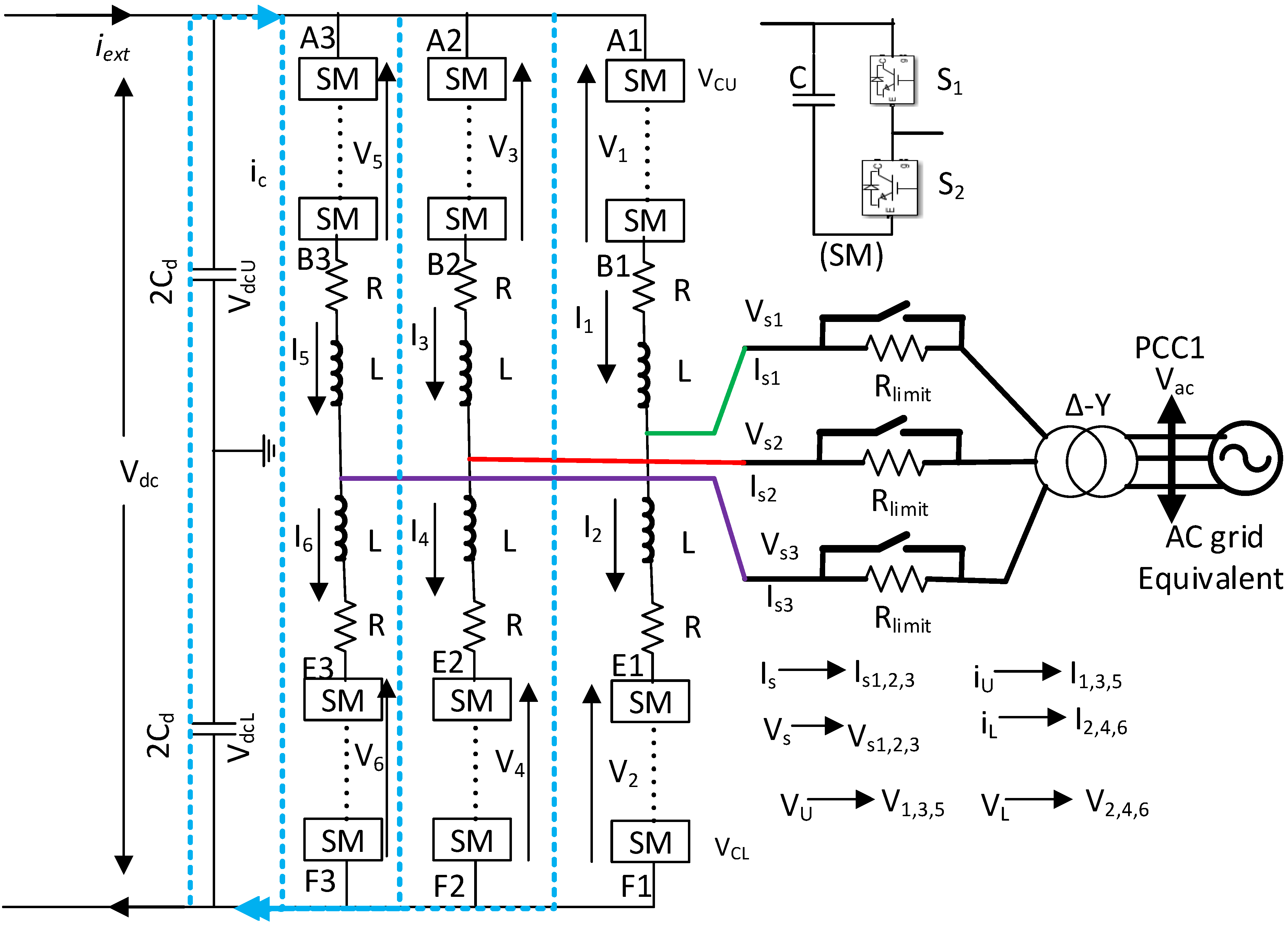
The MMC is the central part of the HVDC transmission system. The equivalent electrical circuits of the MMC1 used in this research are presented in Figure 3. It also requires submodule balancing control and arm-circulating current control in addition to the outer and inner current loops.
The MMC’s current control dynamics in the steady state dq frame are represented by [72,73,74].
L 2 d i s d d t + R 2 i s d = L 2 ω 0 i s q + V d V s d
L 2 d i s q d t + R 2 i s q = L 2 ω 0 i s d + V q V s q
The following equation governs the HVDC-link voltage:
( C d + 6 C N ) d V d c d t = i e x t i s d
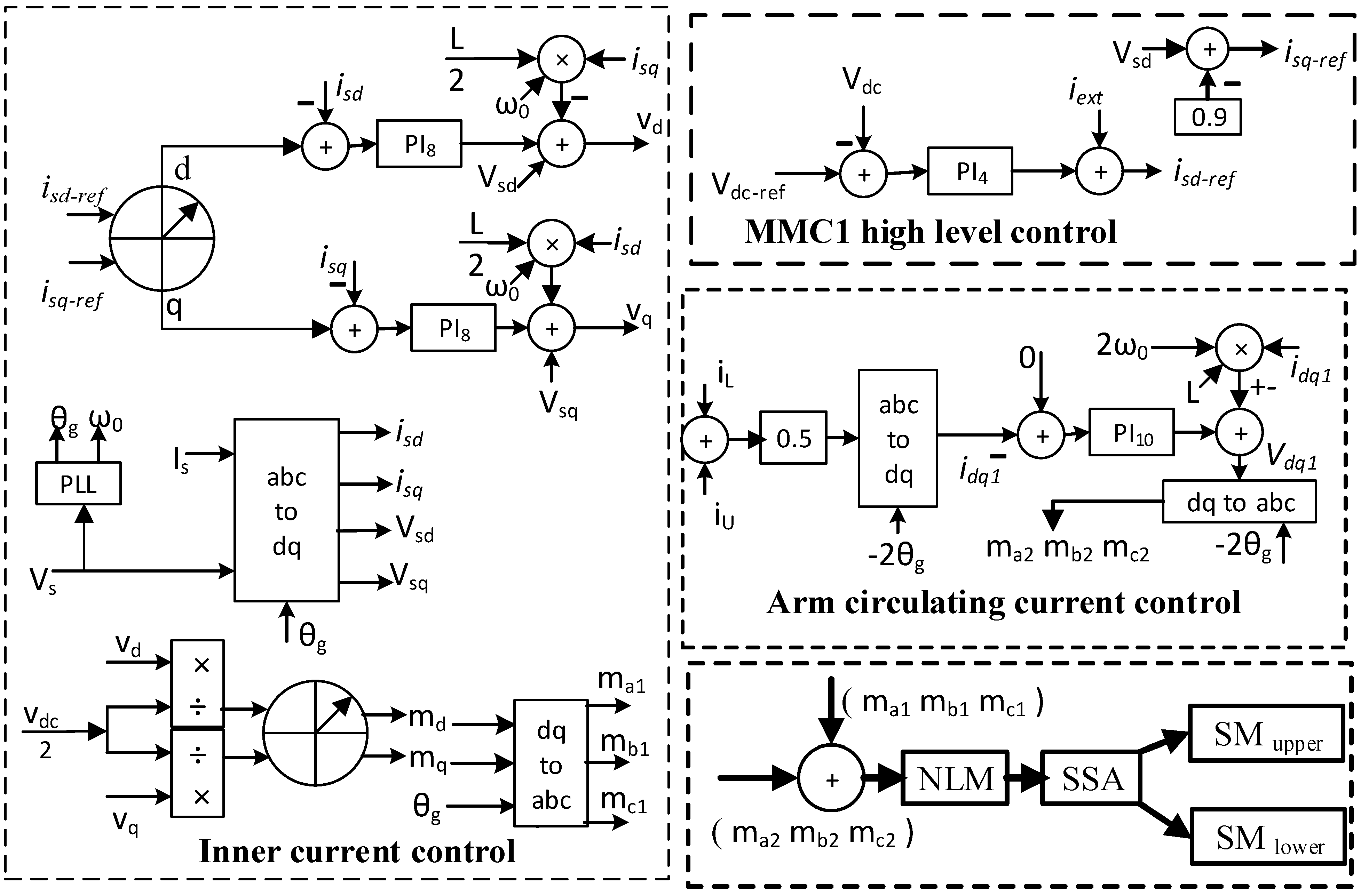
The inner current control loop, which produces the modulating signal for the MMC converter, is formed by Equations (2) and (3). The inner current control loop is shown in Figure 4. The HVDC-link voltage control of MMC1 is also shown in Figure 4, based on Equation (4). A circulating current controller and inner current control are required to ensure a balanced current between the top and bottom arms. The circulating current cycles at 2ω0 Hz, and their dynamics, are governed by the equation below [73]:
d i d 1 d t + R i d 1 = 2 L ω 0 i q 1 + V d 1
d i q 1 d t + R i q 1 = 2 L ω 0 i d 1 + V q 1
In the above Equations (5) and (6), the d-q-current transformed from the MMC’s three arms differential (the arm’s upper and lower) current is i d 1 and i q 1 . The PI controller generates the necessary adjustments in terms of V d 1 and V q 1 , which are then converted into modulating signals. The angle for converting circulating current to dq-frame, and V d q 1 to modulating signal, is −2θg, as shown in Figure 4. Nearest level modulation (NLM) selects the submodule’s number after merging the modulating signals from the inner current control and circulation current control. In addition to the circulating current, the submodule (SM) capacitor voltage within each arm drifts. Such drifts are caused by unregulated charging and discharge. To reduce voltage imbalance between the SMs, a higher voltage SM is placed when the current leaves; in contrast, a lower voltage submodule is placed when the current enters. This article uses a submodule-sorting algorithm (SSA) to insert a suitable submodule from the submodule set in the bottom and top arms, as per the current direction and the submodule capacitor voltage. Figure 4 shows the arm-circulating current control and submodule voltage-balancing control.

3. Proposed Energy Management System

The low-voltage fault at the PCC1 of the MMC1 side limits MMC1′s power transfer capability, which raises the HVDC-link voltage. Usually, the DBR is placed in parallel with the transmission line for dissipation of the surplus energy to regulate the HVDC-link voltage within limits. To dissipate a significant quantity of the HVDC power during the three-line-to-ground (LLLG) low-voltage fault at the PCC1 of the AC grids, several series-parallel combination semiconductor switches are needed. The HVDC connection voltage is subject to multiple switching introduced by the dynamic braking resistor, which may cause variations in the real power flow. Solar and wind energy are highly intermittent and change with the solar radiation, temperature, and wind speed change. Therefore, battery-based energy storage has been considered to address intermittency, smooth out the fast transients, and match users’ demands. Additionally, a battery is utilized to remove the DBR from the system. However, the battery is far away from the HVDC-link and placed with the same AC bus that connects wind and solar energy. This work proposes a battery-based, novel energy management system to protect the HVDC-link voltage and mitigate fluctuation caused by solar and wind energy variation. The purpose of the MMC2 controller is to control the AC link voltage used to integrate renewable energy and energy storage.

3.1. Surplus Energy Control Strategy in the HVDC Link during Low-Voltage Faults at PCC1

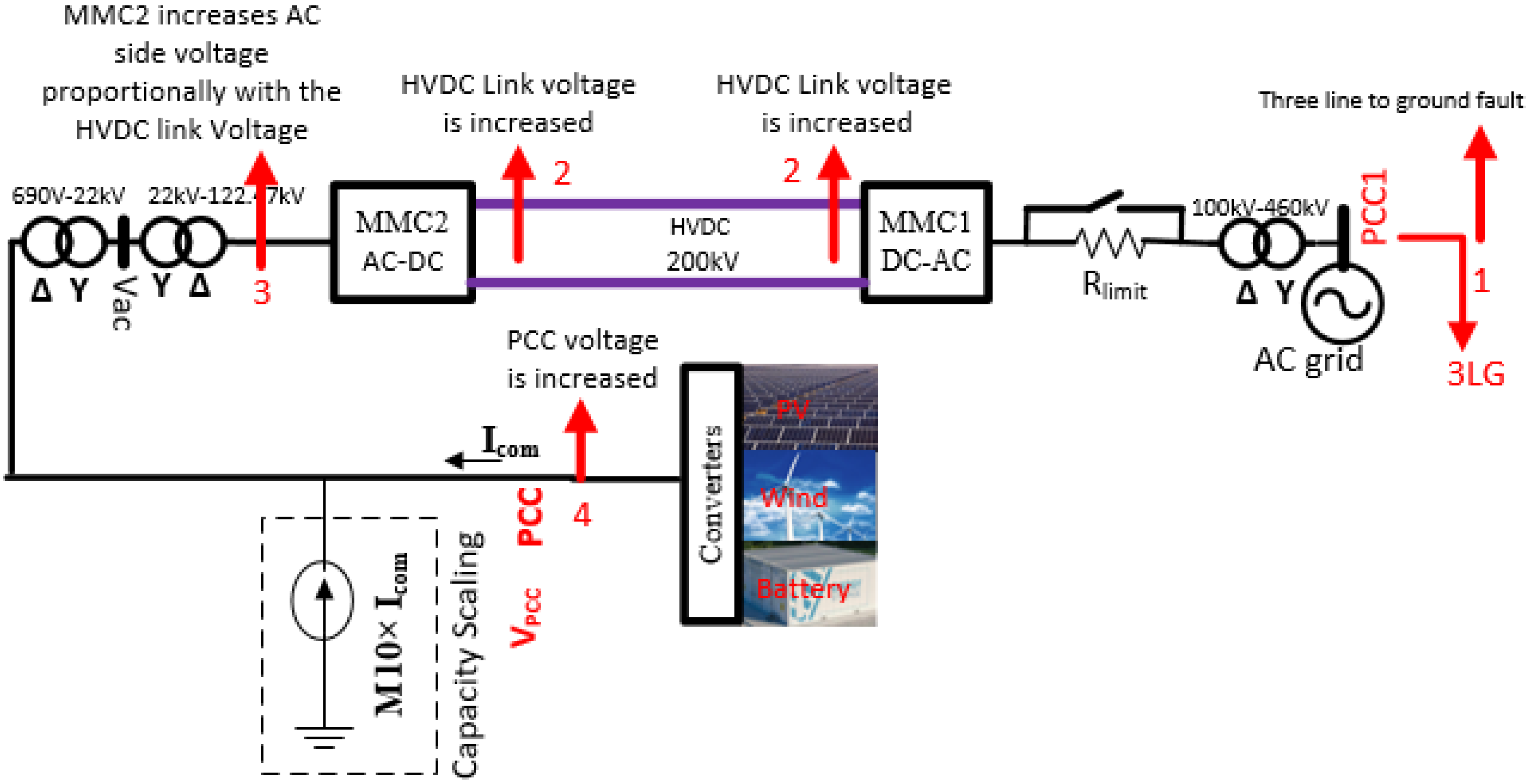
In the event of an unusual HVDC-link voltage rise due to any faults at the PCC1, the MMC2 controller shifts its operation from the constant AC voltage to varying AC voltage control, which increases the PCC voltage. The overall changes in the system are illustrated in Figure 5. The detailed changes are described as follows.
(1)
A Three-phase-to-ground low-voltage fault occurs at PCC1.
(2)
This low-voltage fault reduces the power delivering capacity of MMC1, which in turn increases HVDC link voltage due to excess energy in the HVDC link.
(3)
The reference AC voltage for the MMC2 control loop changes from fixed to variable, and increases with the HVDC-link voltage. Consequently, the AC side voltage of the MMC2 rises. As can be seen from Figure 6a, the reference voltage for MMC2 AC link is changed from 100 kV to V d c 2 if the HVDC link voltage rises more than 210 kV. 200 kV is the nominal voltage for HVDC link (Vdc). During normal operating mode, the reference AC link voltage is 100 kV.
(4)
The rise in the AC link voltage of MMC2 increases the AC voltage of the PCC point or the magnitude of VPCC. It provides the sensing signal for the charging and discharging controller of the BESS. As can be seen from Figure 6b, an increased VPCC (>1.05 pu) provides a negative real current command that means the battery is charged. Therefore, the solar and wind energy is delivered to the battery due to the charging command, instead of going to HVDC-link. Hence, the HVDC-link voltage remains regulated within its limit. The inner current control loop of MMC2 is the same as MMC1.
In summary, during the low-voltage faults at PCC1 of MMC1, the AC voltage control strategy of the MMC2 controller, as shown in Figure 6a, raises the AC side reference voltage (Vsd-ref) slightly with the HVDC-link voltage. As a result, it increases the PCC voltage, which is then used as the battery controller’s input command. To preserve the HVDC-link voltage in the PV-wind-battery-coupled MMC-HVDC system, the excess energy is delivered to the battery if the PCC voltage increases beyond 1.05 pu, as displayed in Figure 6b. The battery side converter (VSC-B) controls the battery charging and discharging. It has an outer loop to generate the reference current, and an inner current control loop to follow the reference current. The constant power reference yields the reference current. The reference real current is obtained by the following [71]:
I g d r e f = P B a t t e r y 1.5 × V g d
Here, V g d is the d-axis voltage of VPCC.
The reactive current of the battery side converter is maintained at zero. PBattery is the reference battery power generated from the VPCC voltage error or from the power fluctuation caused by the wind speed or solar radiation variation. The inner current dynamics of the VSC-B converter in the dq-frame are expressed using the following equation during the steady-state condition [71]:
L d i g d d t + R i g d = L ω 0 i g q + V d V g d
L d i g q d t + R i g q = L ω 0 i g d + V q V g q
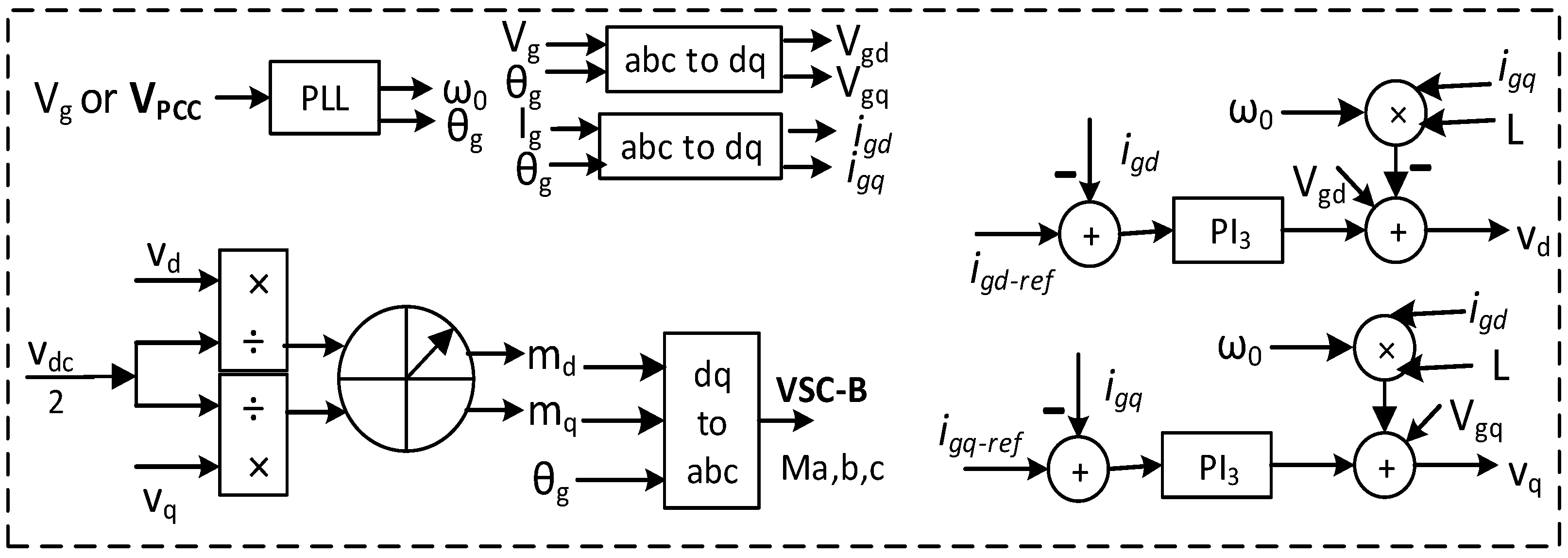
Equations (8) and (9) dictate the current dynamics of VSC-B using the dq voltage of the converter for the generation of the modulating signal (Ma,b,c). The current control loops of the battery side converter are presented in Figure 7. The proportional-integral (PI) controller (PI3) follows the reference current. After comparing the modulating signal with the triangular carrier wave, the PWM gate pulse is produced.

3.2. Renewable Energy Intermittency Improvement Control Strategy

The combined nominal power of the PV and wind generator equals the maximum set point (PSet) for battery’s charging or discharging power. The battery covers any departure from the rated PV power induced by the variable temperature and solar irradiance during normal PCC voltage, as presented in Figure 6c. Similarly, the battery fills any power variation from the nominal wind power induced by wind speed changes. The battery is discharged if it receives a positive power command, and charges if it receives a negative power command. The PV inverter and wind generator side converter operate in peak power tracking in both normal and abnormal conditions at PCC1 and PCC.

3.3. Charging and Discharging Control during Normal Voltage at PCC

The charging and discharging of battery is performed by making the reference power PBattery negative or positive of the outer control loop of VSC, as shown in Figure 6d. The positive value of PBattery indicates that the battery is being discharged, while the negative value refers to battery charging. The battery is rated for 4 MW for 15 min, which implies that if a 4 MW steady power injection is maintained for 15 min, the battery will be fully charged. The battery is generally depleted at night and fully depleted if 4 MW continuous power is delivered for 15 min into the PCC terminal. It is worth noting that the PCC voltage remains constant during battery charging and discharging. Any symmetrical and asymmetrical voltage disturbance affects the PCC voltage, which shifts the battery’s regular power leveling mode to HVDC-link’s excess energy control mode. Furthermore, the battery charging and discharging thresholds are 95 percent and 15 percent, respectively. During symmetrical and asymmetrical faults at PCC1, the battery is kept below 100% charge to facilitate surplus power control in the HVDC-link.

4. Result and Discussion

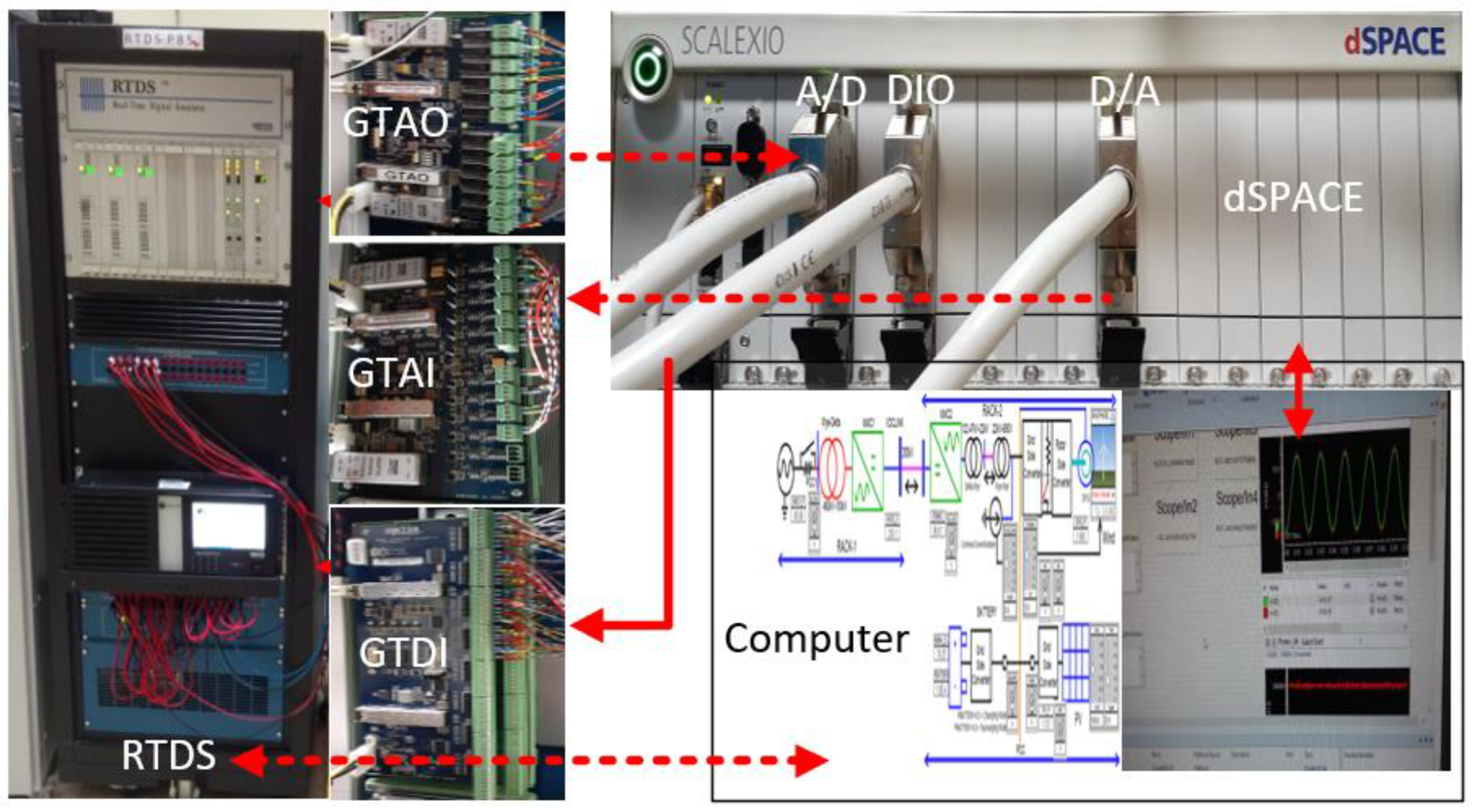
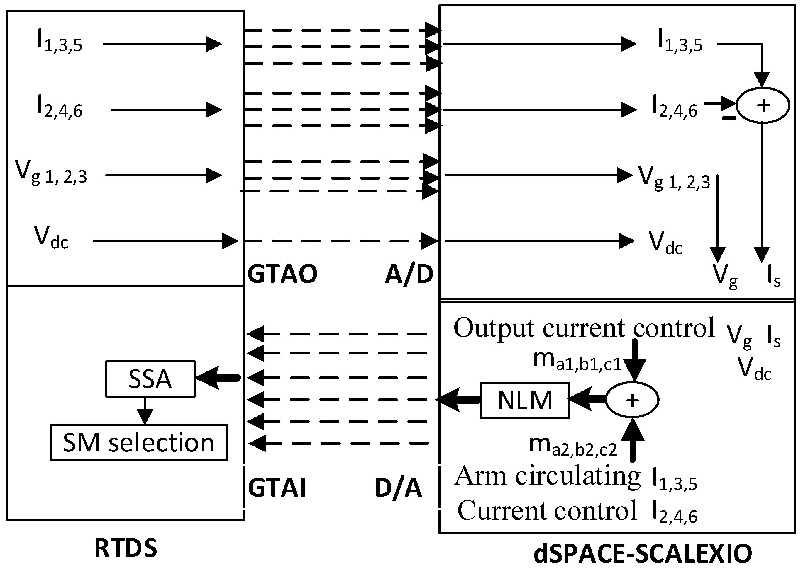
The MMC and dSPACE controllers have a sample time of 100 µs, while the other controller has a sample time of 50 µs. Due to the extensive system’s complexity, a multi-rack RTDS platform was utilized to implement the entire system. The RTDS multi-rack hardware platform was made up of a Nova Core and PB5 CPUs. The Rack-2 has MMC2 with PV, wind, and battery, while the Rack-1 has MMC1. The dSPACE controller was used to implement the MMC1 controller. The dSPACE-RTDS hardware setups, runtime interface, and MMC1 controller signal in the dSPACE controller are shown in Figure 8, Figure 9 and Figure 10, respectively. A 100 MW (megawatts) PV-wind-battery system was modeled by scaling the PCC terminal input current from one entire 1.74 MW PV array and one 2 MW wind generator unit with a battery system. Table 2 and Table 3, as given in the appendix, provide the required information on the MMC-HVDC system used in this article.

4.1. HVDC-Link Voltage Control during Low-Voltage Faults at PCC1

A power system network is large complex network and is subject to low-voltage faults. During low voltage, the power transfer capacity of the converter is reduced significantly, which in turns causes the HVDC link voltage to rise. Therefore, a proper protection scheme is provided to control surplus energy for HVDC voltage regulation. A dynamic braking resistor-based traditional controller for HVDC link voltage regulation during low-voltage faults is presented in Figure 11. It is clearly visible from Figure 12 that the excess energy in the HVDC link is dissipated across the parallelly connected DBR during low-voltage faults. Although DBR controls the HVDC link voltage, it introduces several switches that affects the HVDC voltage as well as the power flow.
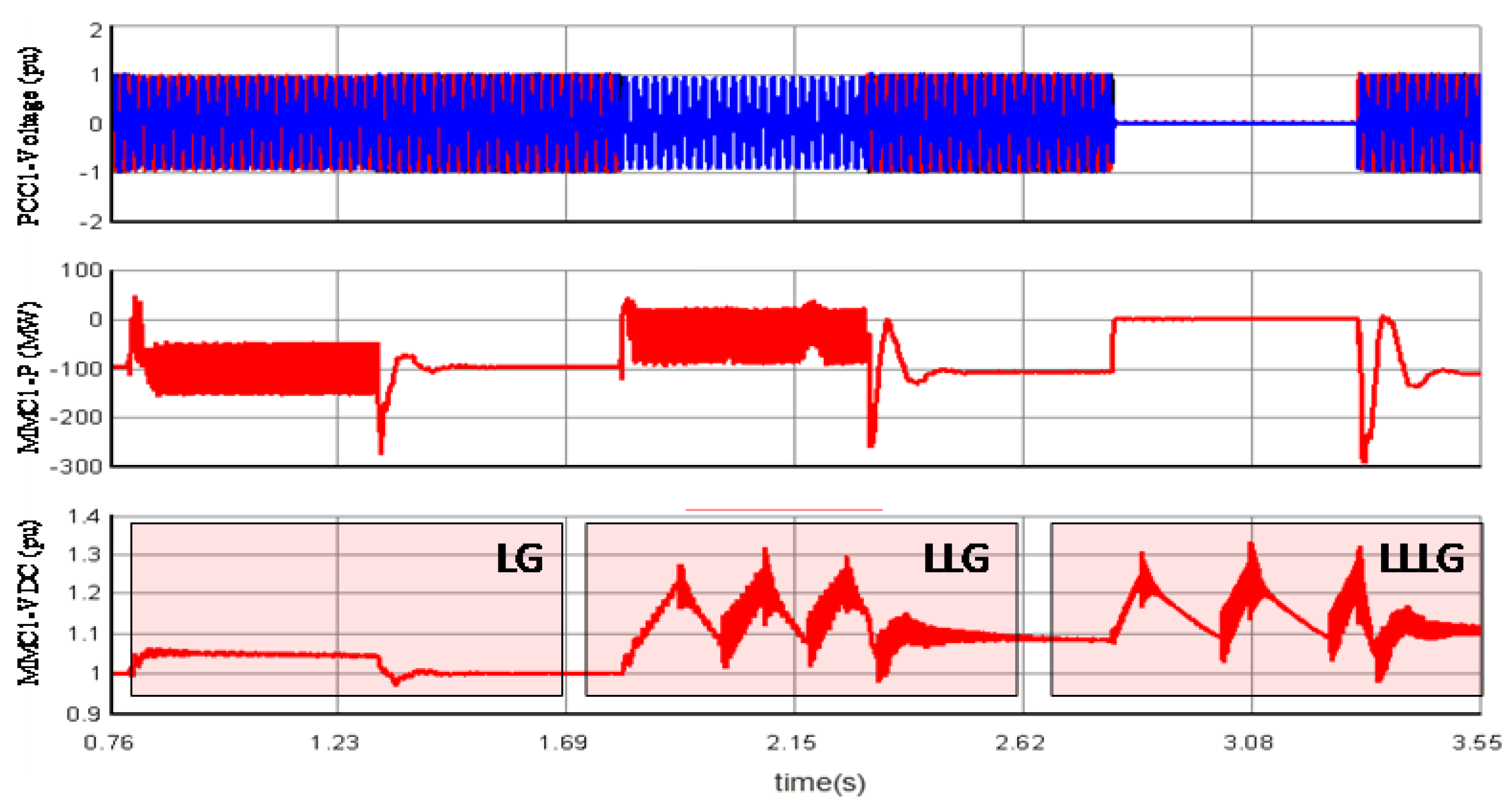
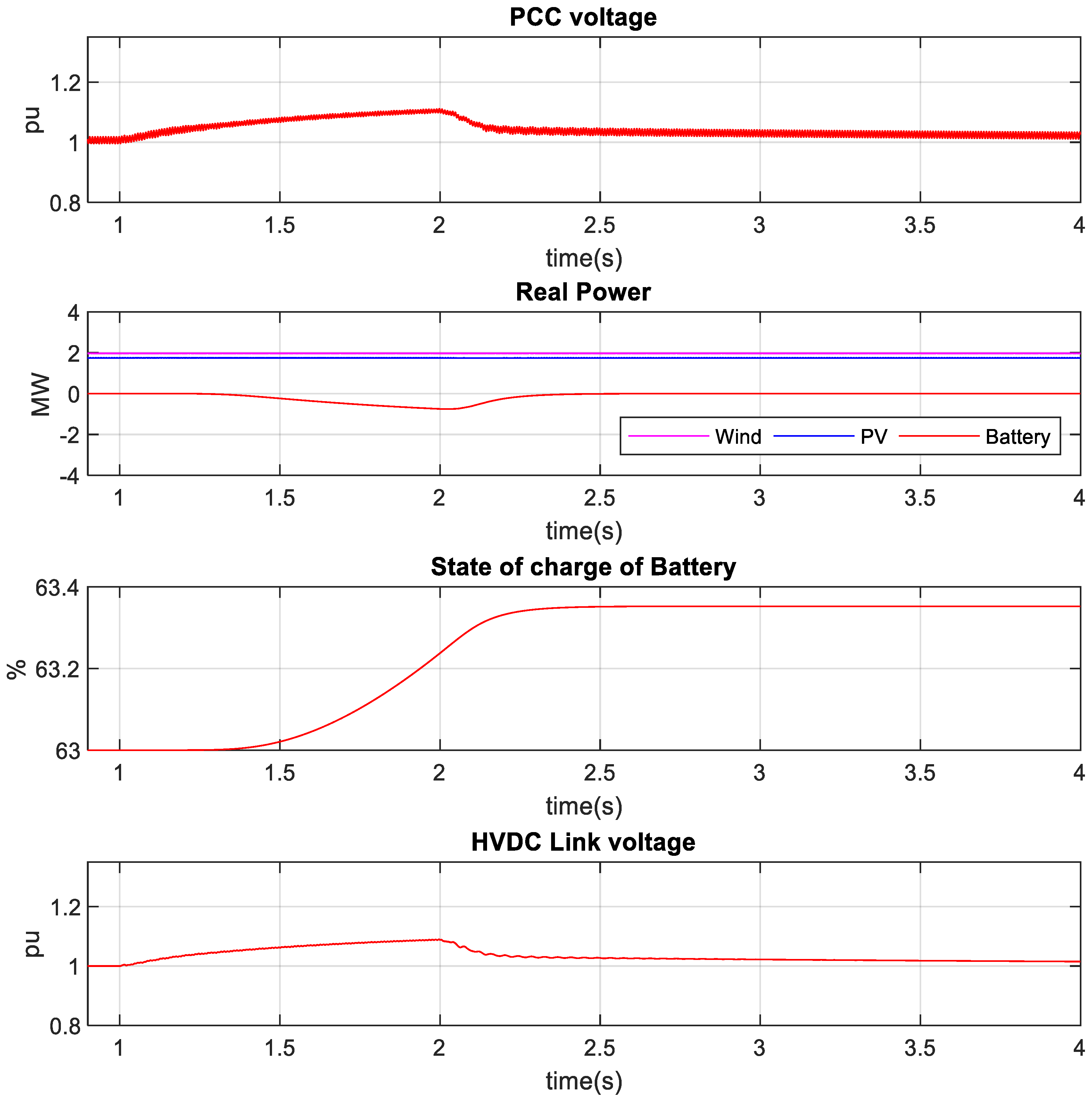
The proposed work controls the HVDC link voltage without the DBR. The severe balanced and unbalanced faults were applied at PCC1 to test the battery controller’s efficacy in controlling the HVDC-link voltage within the threshold for the PV-wind-battery-coupled MMC-HVDC network. During the fault at PCC1, the battery absorbed the surplus energy from the HVDC-link, while PV and wind generation were unaffected. As shown in Figure 13, a one-second duration LLLG fault is introduced to PCC1 at 1 s. During the three-phase-to-ground faults at PCC1, the MMC1’s provided real power decreased to a minimum, as seen in Figure 14. PV and wind power generation stayed stable during the fault by proportionately charging the battery to increase the PCC voltage, as illustrated in Figure 15. The PV and wind energy were transferred to the battery when the PCC voltage surpassed 1.05 pu, keeping the HVDC-link voltage around 1.2 pu. The battery SOC was raised from 60% to 63% throughout this time. The line-to-line-ground (LLG) fault, like the LLLG fault, was a 1 s duration low-voltage fault introduced to PCC1, as illustrated in Figure 16.
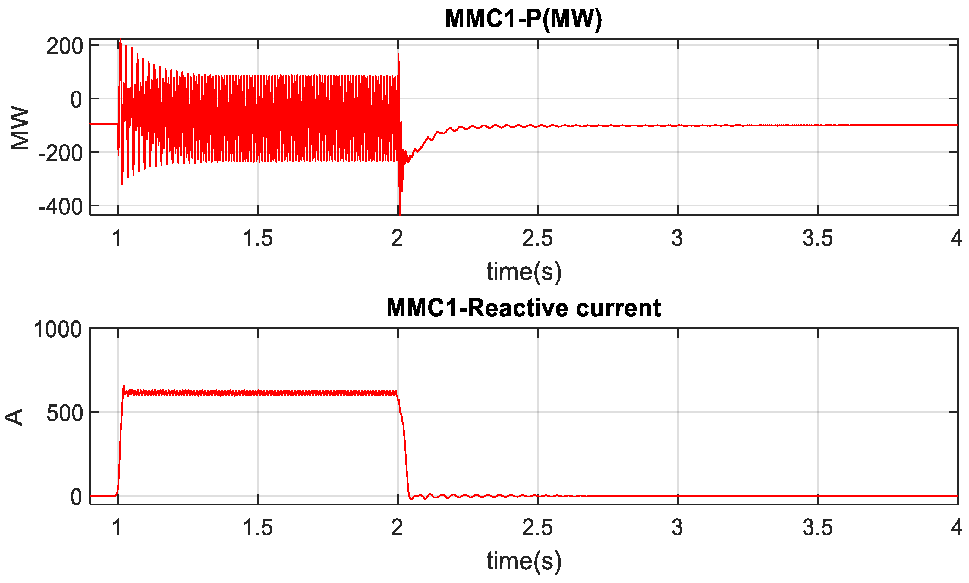
During the LLG fault at PCC1, the MMC1’s provided real power is reduced, whereas the injected reactive current is increased, as seen in Figure 17. As shown in Figure 18, an LLG fault at PCC1 raised the high-voltage transmission line voltage, which increased the AC voltage magnitude of PCC. As a result, when the AC voltage magnitude of PCC surpasses 1.05 pu, the battery was charged, while PV and wind power remain constant. The HVDC-link voltage has been restricted to 1.06 pu due to battery charging. However, compared to the LLLG fault, the energy transferred to the battery was lower. Figure 17, on the other hand, shows that the MMC1 delivered approximately 50 MW to PCC1 during a low-voltage LLG fault, which was more than a low-voltage LLLG fault. The battery SOC rose from 63% to 63.3% during the LLG failure. The battery efficiently controlled the surplus energy from the high-voltage transmission line in all circumstances, protecting the HVDC-link without needing PV and wind power reduction or a dynamic braking resistor. In addition, during low-voltage LLLG and LLG faults at PCC1, the MMC1 injected approximately 720 A and 600 A reactive current, respectively, as can be seen in Figure 14 and Figure 17.

4.2. Power Smoothing for PV System under Solar Irradiance and Temperature Change

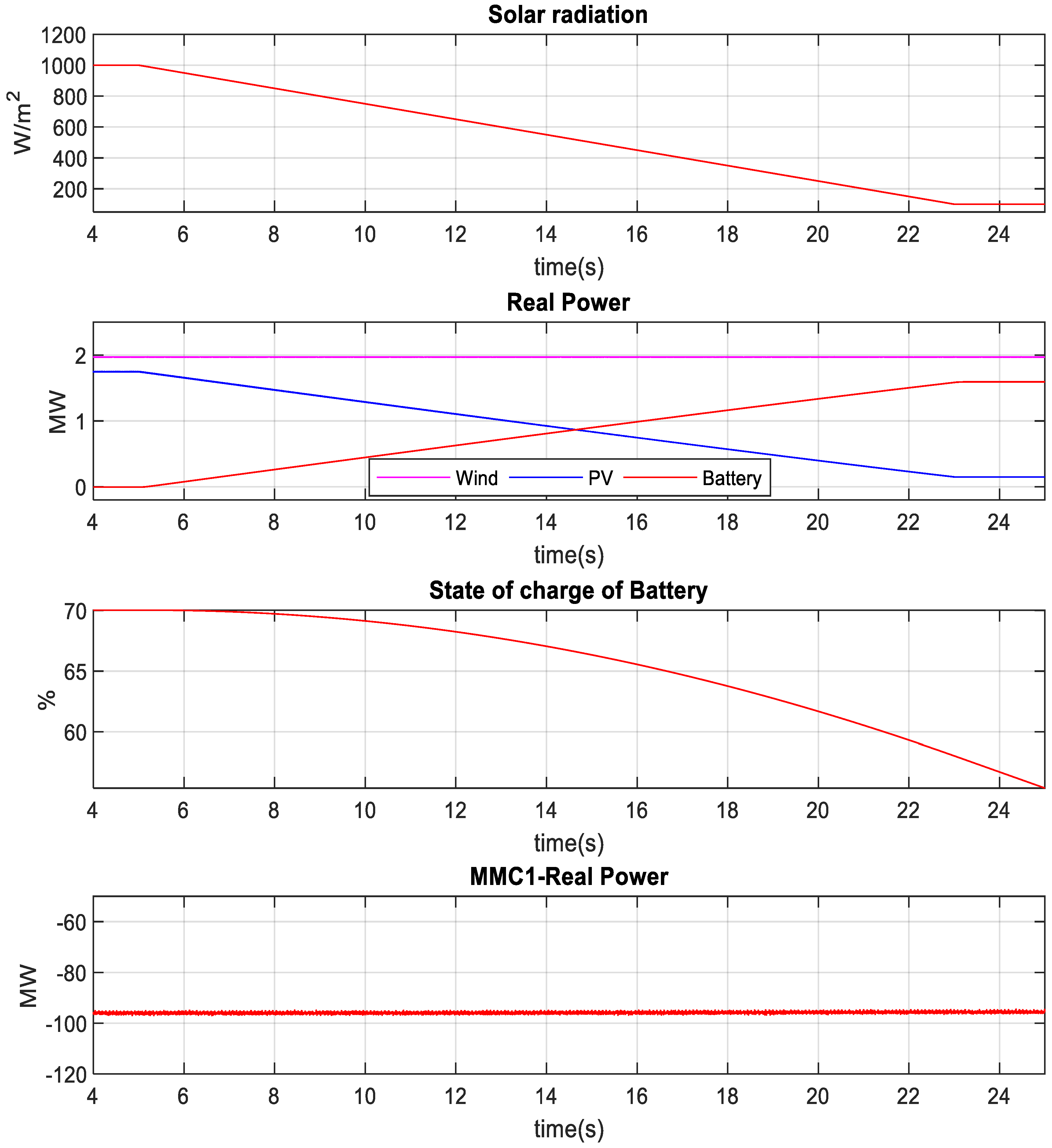
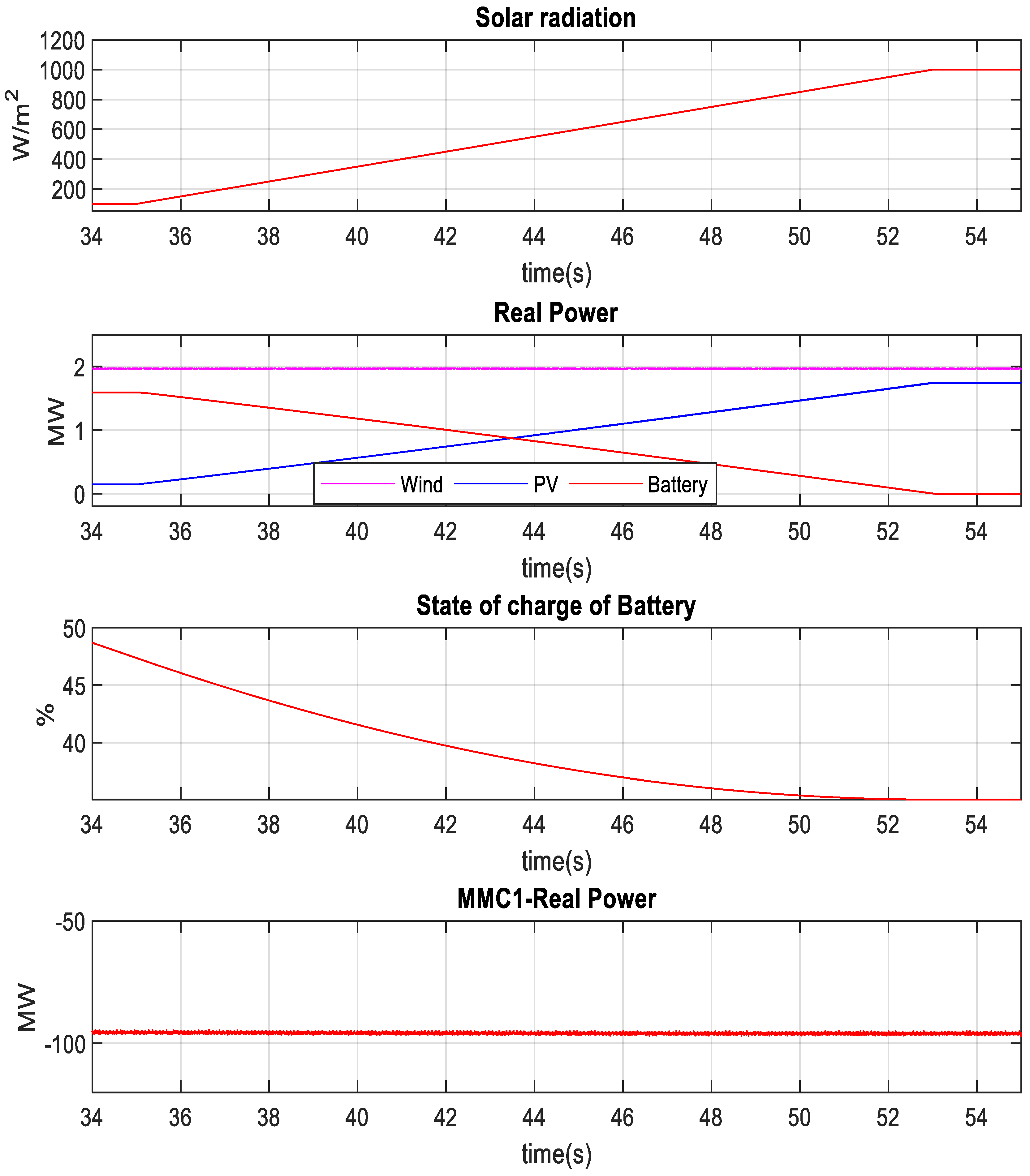
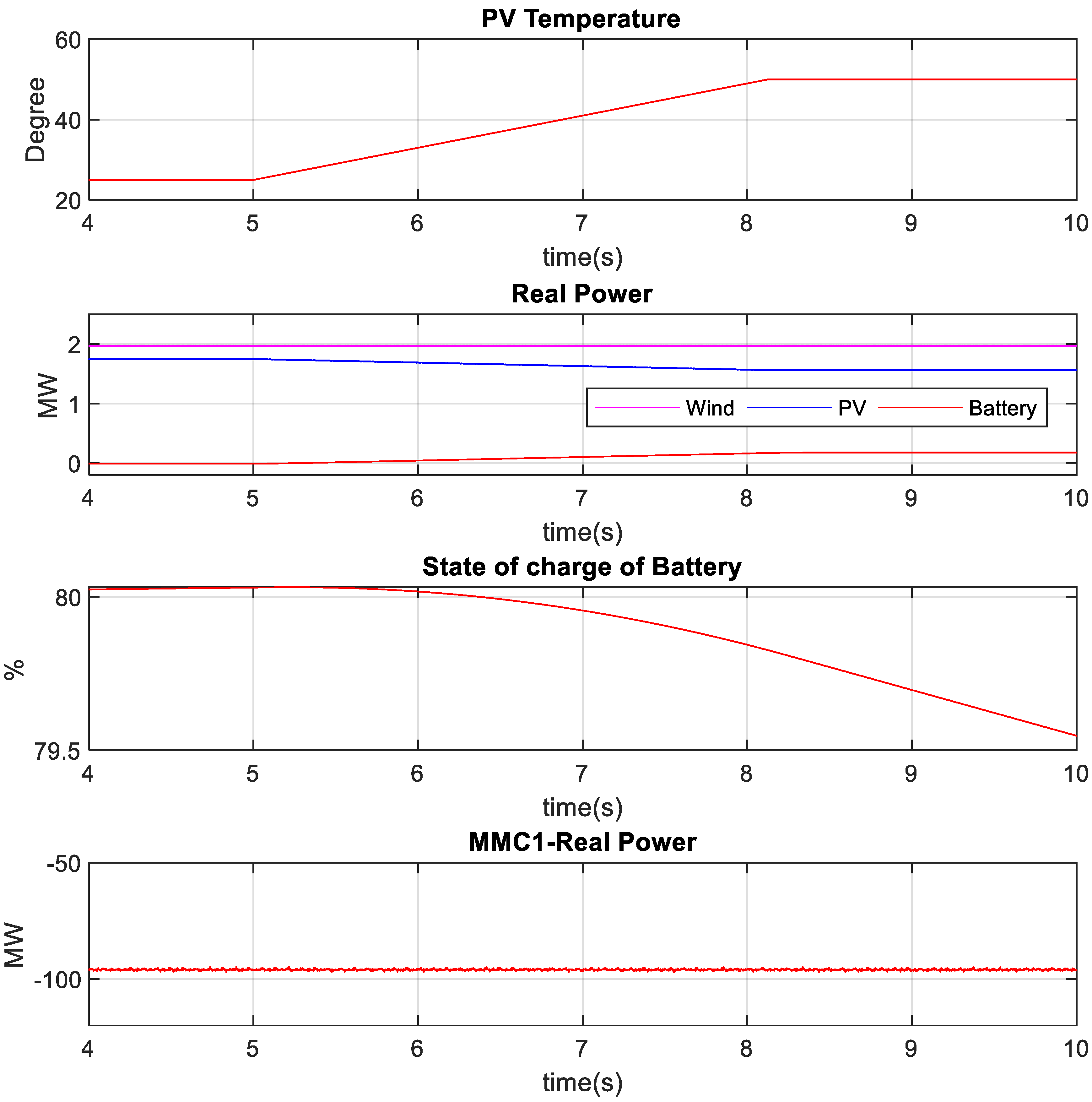
To test the battery controller’s efficacy, solar irradiance was reduced from 1000 Wm−2 to 100 Wm−2. As shown in Figure 19, the battery compensated for the PV power deficit caused by reduced solar radiation. The PV output was reduced to 0.1 MW from 1.74 MW, while the battery power was increased to 1.6 MW from 0 MW. As a result, the battery SOC was reduced to 55% from 70%. The interaction between the PV and BESS kept the MMC1 power delivery almost constant. Likewise, when solar radiation was changed from 100 Wm−2 to 1000 Wm−2, the battery power dropped from 1.6 MW to zero, as seen in Figure 20. As a result, the PV output grew to 1.74 MW from 0.1 MW and battery SOC reduced to 35% from 49%. During the transition, real power delivered by the MMC1 did not experience any overshoot. Figure 21 and Figure 22 show that the battery compensated for the PV power fluctuation induced by temperature variation. As shown in Figure 21, the temperature was increased from 25 to 50 degrees Celsius, lowering the PV output to 1.55 MW from 1.74 MW. As a result, the battery power was raised to 0.2 MW from zero to compensate for the deficit, keeping the MMC1 supplied power constant. Similarly, during the temperature drop from 50 °C to 25 °C, battery power was lowered to zero from 0.2 MW, and PV power was raised to 1.74 MW from 1.55 MW, as shown in Figure 22. During such a transition, the real power delivered by the MMC1 did not experience any overshoot.

4.3. Battery-Based Power Smoothing under Wind Speed Variation

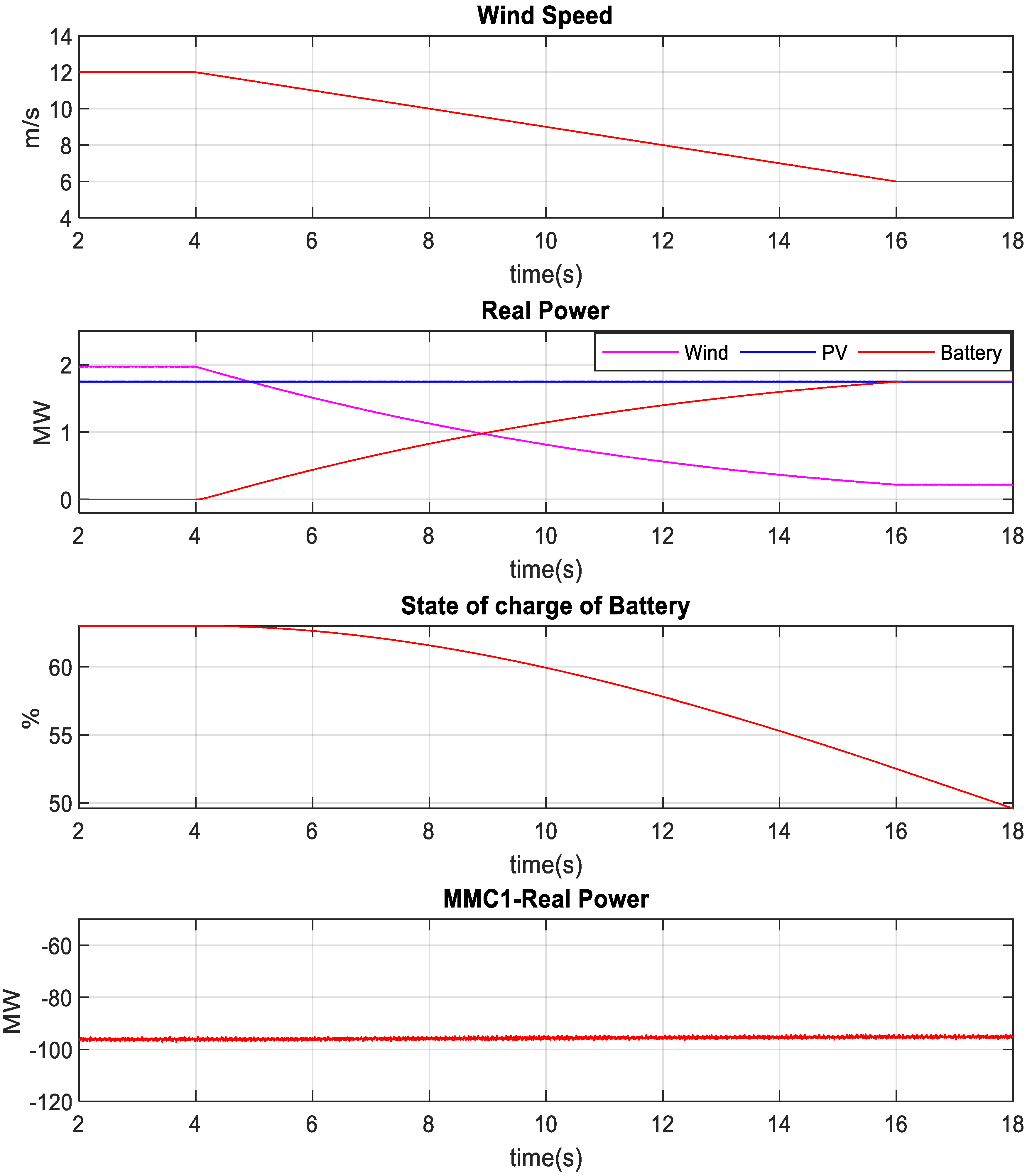
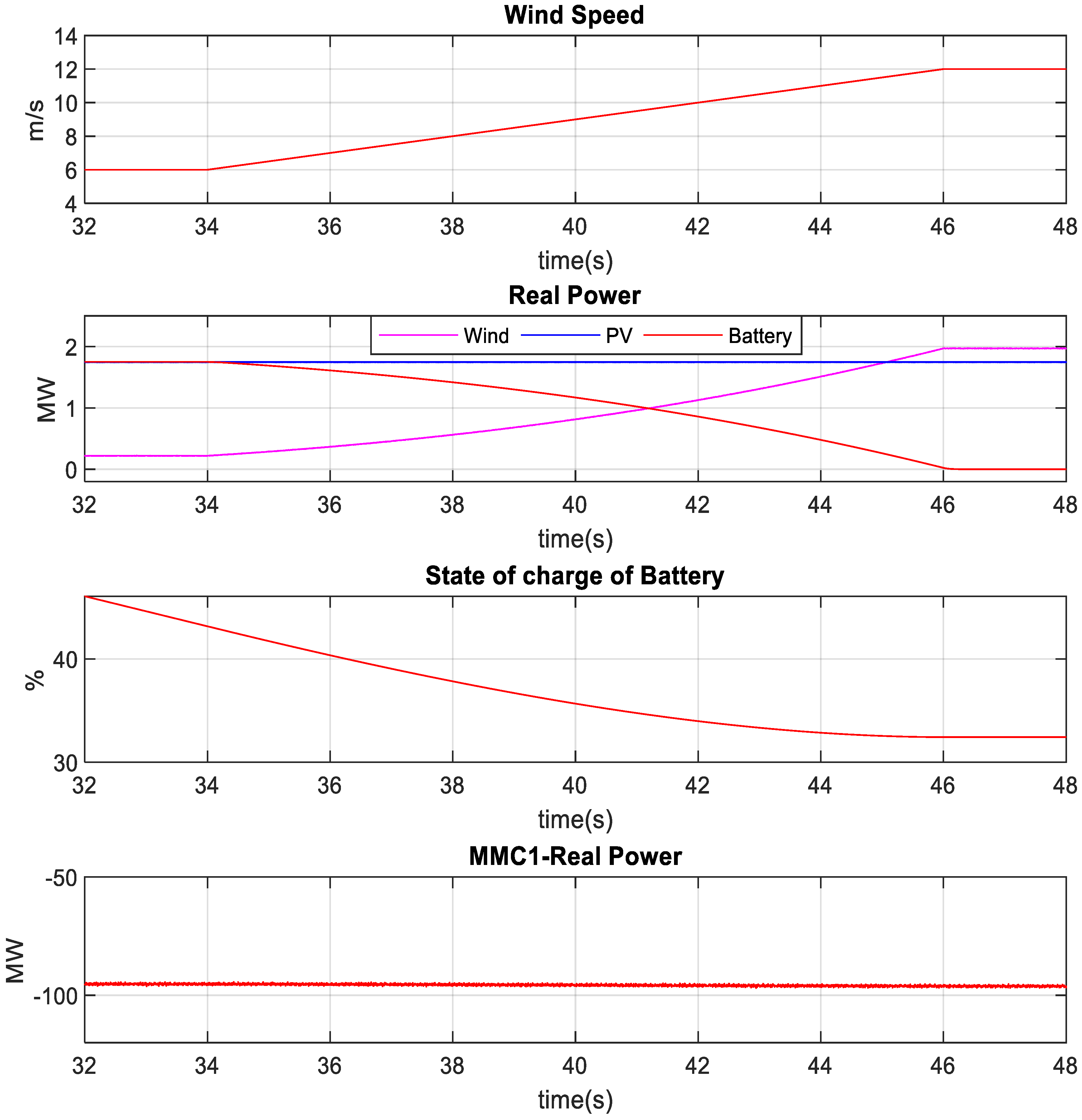
To test the battery controller’s efficacy, the wind speed was varied from 12 ms−1 to 6 ms−1. The battery compensated for the reduced power due to the lower wind speed, as shown in Figure 23. The battery power was raised from zero to 1.75 MW as the wind power was reduced from 2 MW to 0.25 MW. Thus, the battery’s SOC was reduced from 64 percent to 50 percent throughout this time. The active power delivered by the MMC1 was almost constant. Likewise, when the wind speed was changed from 6 ms−1 to 12 ms−1, battery power dropped from 1.75 MW to zero, as seen in Figure 24. Wind power was raised from 0.25 MW to 2 MW during this time, and battery SOC was reduced from 45 percent to 30 percent. During the transition, the MMC1 provided real power and did not experience any overshoot, as the battery controller effectively responded to the change in the wind farm due to wind speed variation.

4.4. Power Smoothing under Solar Irradiance and Wind Speed Variation

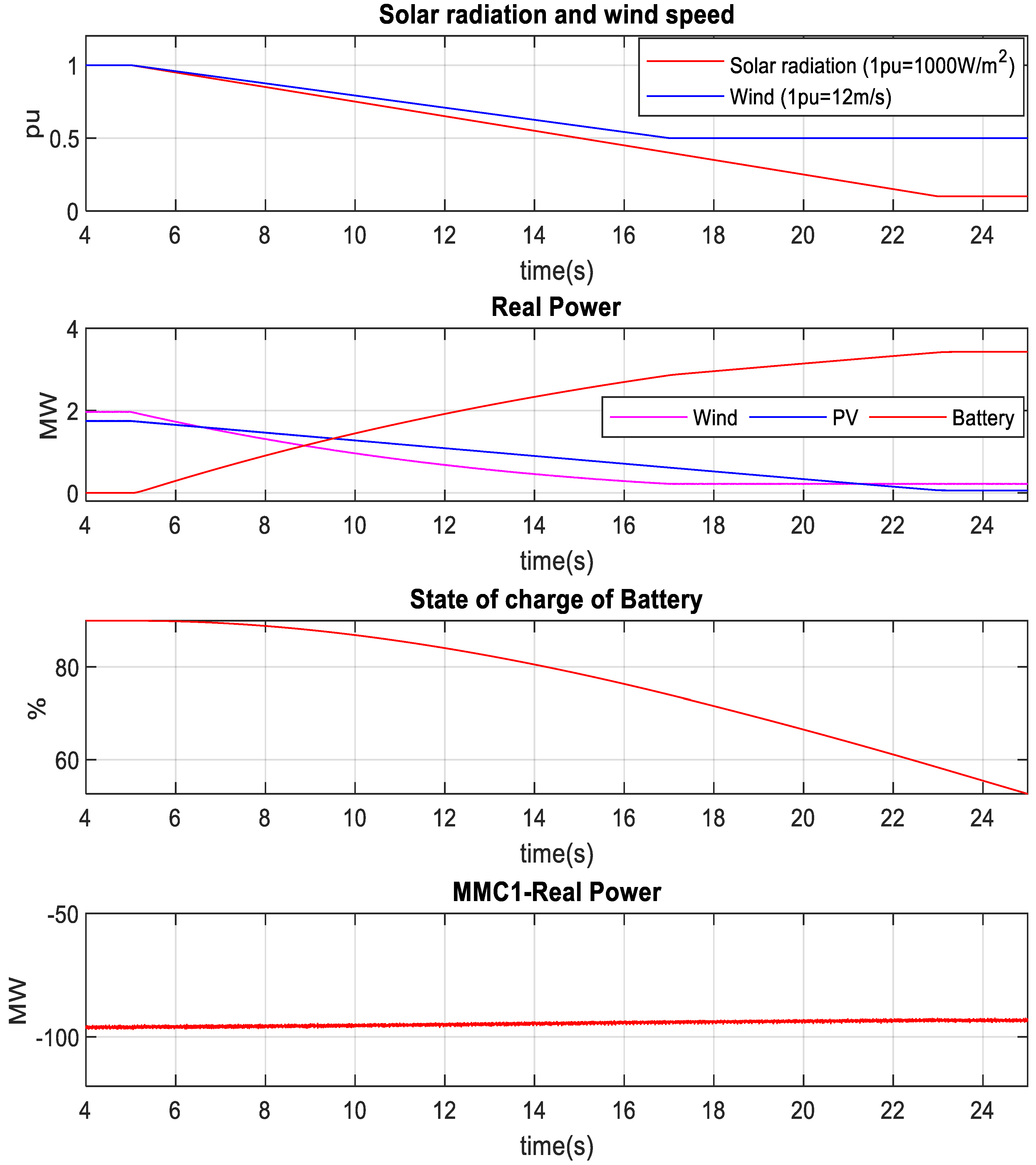
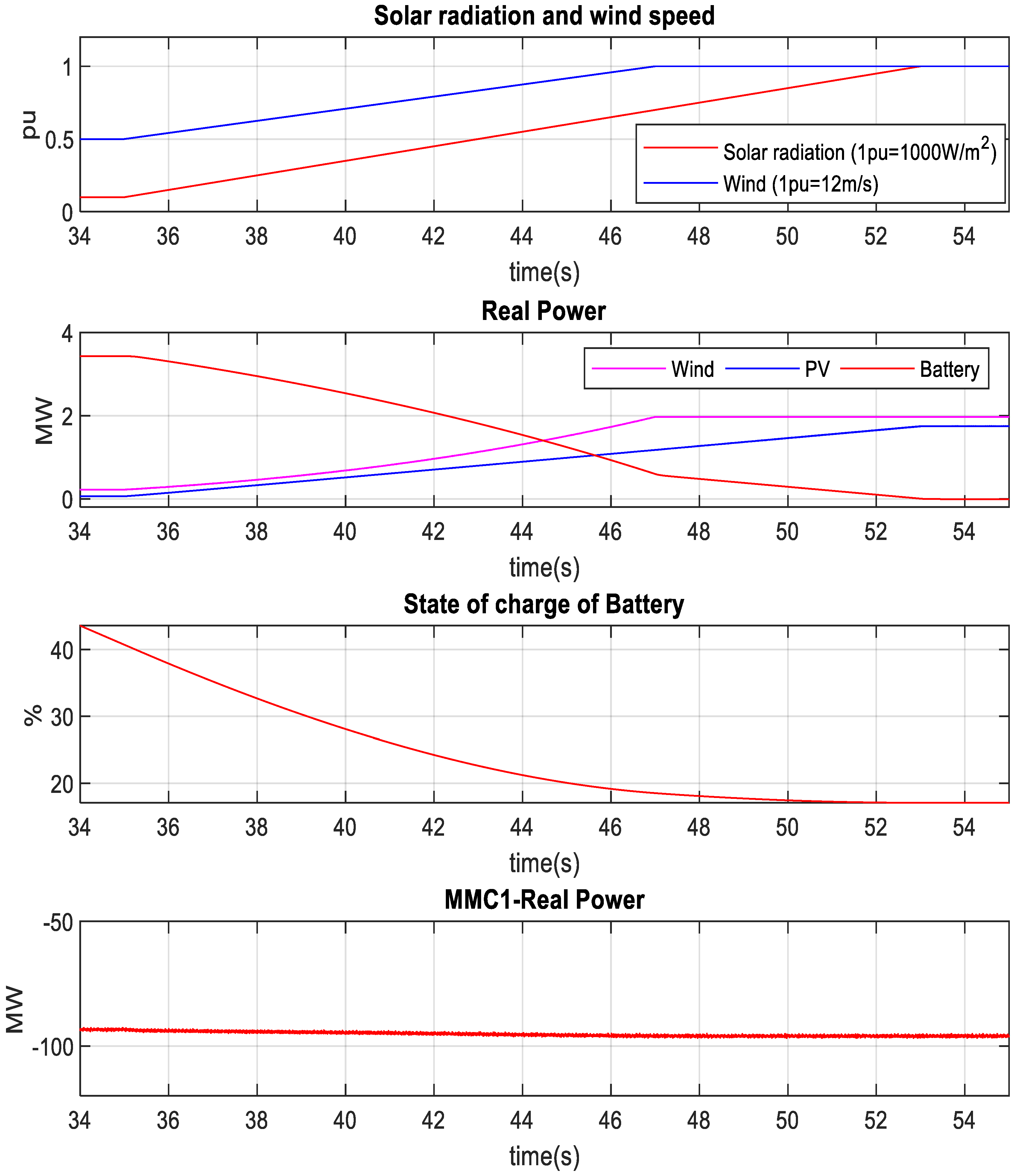
In this section, the solar radiation for the PV system and the wind speed for the wind farm were simultaneously varied to test the effectiveness of the battery controller. The radiation was reduced from 1000 Wm−2 to 100 Wm−2, whereas the wind speed was reduced from 12 ms−1 to 6 ms−1, as shown in Figure 25. Thus, the PV output was dropped from 1.74 MW to 0.1 MW, and the wind farm power was lowered from 2 MW to 0.25 MW. In response to the changes in RER output powers, the BESS injected the required power to keep the MMC1 output constant, lowering the battery SOC from 85 to 56 percent. Likewise, when the wind speed was changed from 6 ms−1 to 12 ms−1, and the solar radiation was varied from 100 Wm−2 to 1000 Wm−2, the power injection from the battery was dropped from 3.4 MW to zero, as shown in Figure 26, as the PV and wind systems outputs reached to their rated power. As a result, the battery SOC was reduced from 44% to 20% during the transition period. Finally, it is evident from Figure 26 that the MMC1 delivered almost the same power without experiencing any overshoot even under simultaneous variations in solar irradiation and wind speed due to the effective operation battery controller.

4.5. Charging of Battery

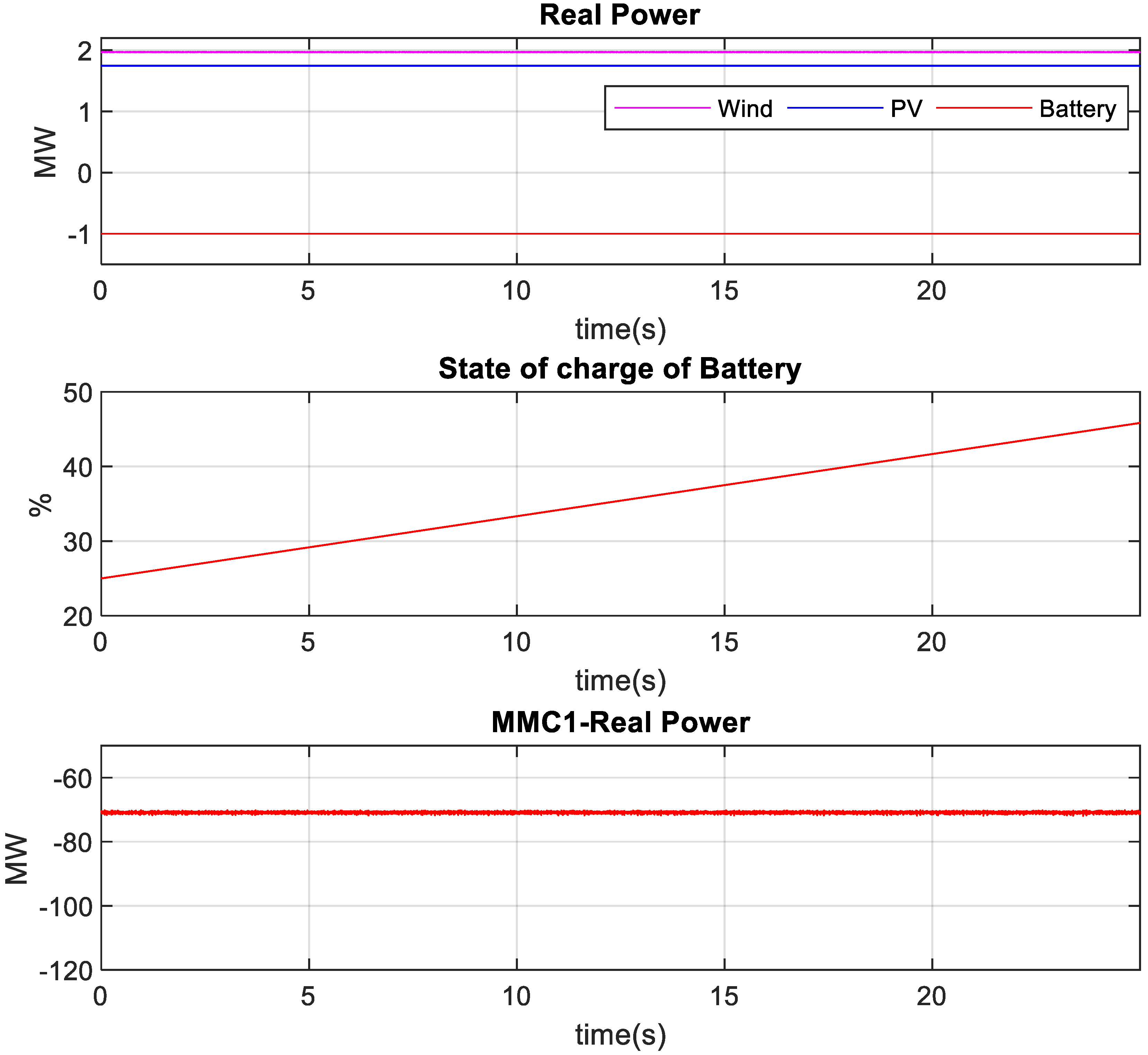
The charging and discharging of battery is performed by making the reference power PBattery negative or positive of the outer control loop of VSC, as shown in Figure 6d. The positive value of PBattery indicates that the battery is being discharged, while the negative value refers to battery charging. The charging of the battery is depicted in Figure 27. The PBattery was set to a constant value (−1 MW), resulting in a net power injection into the BESS. As a result, the power injection at PCC1 from 26 PV units and wind farms fell from roughly 96 MW to 72 MW. The battery is rated for 4 MW for 15 min, which implies that if a 4 MW steady power injection is maintained for 15 min, the battery will be fully charged. However, the duration was set to 30 s for the simulation to highlight the major charging profile change in a short period. During this time, the battery SOC was raised from 25 percent to 45 percent.

5. Conclusions

A battery-based control method was devised to successfully control the HVDC-link surplus power and keep voltage within limits under low-voltage disturbance at the PCC of AC grids. In addition, another control strategy was developed for smoothing power fluctuations due to solar radiation, temperature, and wind speed variation. The entire system, including all switching converter models, was simulated and tested with a real-time platform by connecting the dSPACE controller with the RTDS machine by developing the controller hardware in the loop setup. The findings support the use of battery-based surplus power control to preserve the HVDC-link voltage during low-voltage disturbance situations, and the use of a power smoothing control technique to improve transient performance during variations in irradiance, temperature, and wind speed. Furthermore, MMC1 delivered reactive current at the PCC of the AC grids during symmetrical and unsymmetrical faults, improving the low-voltage FRT capability of the MMC-HVDC system. The combination of renewable energy and batteries can be investigated for the frequency regulation of AC grids. In addition, it can also be further explored for inertia emulation and grid forming converters, due to its large power capacity, similar to that of a synchronous generator.

Author Contributions

Conceptualization, M.I.H.; Methodology, M.I.H.; Software, M.I.H., M.S. and M.A.A.; Validation, M.I.H.; Formal analysis, M.I.H., M.S. and M.A.A.; Investigation, M.I.H., M.S. and M.A.A.; Resources, M.A.A.; Writing—review & editing, M.S.; Supervision, M.A.A.; Project administration, M.A.A.; Funding acquisition, M.A.A. All authors have read and agreed to the published version of the manuscript.

Funding

This research received no external funding.

Acknowledgments

The authors acknowledge the research support of the King Fahd University of Petroleum & Minerals (KFUPM) through Grant No: DF201022. The authors acknowledge the support received from the Interdisciplinary Research Center for Renewable Energy and Power Systems (IRC-REPS), KFUPM, Saudi Arabia. Furthermore, the authors acknowledge the support of K.A.CARE Energy Research & Innovation Center (ERIC), at KFUPM.

Conflicts of Interest

The authors declare no conflict of interest.

Nomenclature

Battery Side Converter:
R, LReactor resistance and inductance
PCCPoint of common coupling
ω 0 PCC angular frequency
i g d & i g q PCC d-q axis current
V g d & V g q PCC d-q axis voltage
V d & V q VSC terminal d-q axis voltage
CDC link capacitance
VDCDC link voltage
I d c DC link current
VSC-BBattery side converter
IcomCombined current of PV, wind and battery
M10Scaling factor
HPFHigh pass filter (LF + RF // CF)
BESSBattery energy storage system
P B a t t e r y Battery power
MMC Converter:
R, LArm reactor resistance and inductance,
PCC1Point of common coupling of AC grid 1
ω 0 Angular frequency at PCC1
V s , I s 3-Ø voltage and current
V s d & V s q d-q axis voltage of PCC1
i s d & i s q d-q axis current of PCC1
V d & V q MMC terminal d-q axis voltage,
VDCHVDC-link voltage
I e x t HVDC-link DC current
CSubmodule capacitance
C d DC link pole-to-pole capacitance
NNumber of submodules
i d 1 & i q 1 Negative sequence d-q axis current
V d 1 & V q 1 Negative sequence d-q axis voltage,
LGSingle-line-to-ground
LLGDouble-line-to-ground
LLLGThree-line-to-ground
DBRDynamic braking resistor
MMCModular multilevel converter
HVDCHigh-voltage DC current
Others:
P P V PV panel array power
P w i n d Wind generator power
F R T Fault ride through
P S e t Combined power of wind generator and solar array
RERRenewable energy resources
CHILController hardware in loop
RTDSReal-time digital simulator

References

  1. Hossain, I.; Abido, M.A. SCIG Based Wind Energy Integrated Multiterminal MMC-HVDC Transmission Network. Sustainability 2020, 12, 3622. [Google Scholar] [CrossRef]
  2. Hossain, I.; Abido, M.A. Positive-Negative Sequence Current Controller for LVRT Improvement of Wind Farms Integrated MMC-HVDC Network. IEEE Access 2020, 8, 193314–193339. [Google Scholar] [CrossRef]
  3. Hossain, I.; Abido, M.A. Active Power Control of PV-Battery Connected MMC-HVDC System for FRT Support. Appl. Sci. 2020, 10, 7186. [Google Scholar] [CrossRef]
  4. Zhang, M.; Yuan, X.; Hu, J. Inertia and Primary Frequency Provisions of PLL-Synchronized VSC HVDC When Attached to Islanded AC System. IEEE Trans. Power Syst. 2017, 33, 4179–4188. [Google Scholar] [CrossRef]
  5. Sakamuri, J.N.; Rather, Z.H.; Rimez, J.; Altin, M.; Goksu, O.; Cutululis, N.A. Coordinated Voltage Control in Offshore HVDC Connected Cluster of Wind Power Plants. IEEE Trans. Sustain. Energy 2016, 7, 1592–1601. [Google Scholar] [CrossRef]
  6. Moawwad, A.; El Moursi, M.S.; Xiao, W. Advanced Fault Ride-Through Management Scheme for VSC-HVDC Connecting Offshore Wind Farms. IEEE Trans. Power Syst. 2016, 31, 4923–4934. [Google Scholar] [CrossRef]
  7. Moawwad, A.; El Moursi, M.S.; Xiao, W. A Novel Transient Control Strategy for VSC-HVDC Connecting Offshore Wind Power Plant. IEEE Trans. Sustain. Energy 2014, 5, 1056–1069. [Google Scholar] [CrossRef]
  8. Egea-Àlvarez, A.; Aragüés-Peñalba, M.; Prieto-Araujo, E.; Gomis-Bellmunt, O. Power reduction coordinated scheme for wind power plants connected with VSC-HVDC. Renew. Energy 2017, 107, 1–13. [Google Scholar] [CrossRef]
  9. Hossain, I.; Shafiullah; Al-Sulaiman, F.A.; Abido, M.A. Comprehensive Analysis of PV and Wind Energy Integration into MMC-HVDC Transmission Network. Sustainability 2022, 15, 253. [Google Scholar] [CrossRef]
  10. Hossain, M.I.; Abido, M.; Pathan, M.I. PMSG Based Wind Energy Integration into MMC Based HVDC Transmission Network in RTDS. In Proceedings of the 2020 IEEE Electric Power and Energy Conference EPEC, Edmonton, AB, Canada, 9–10 November 2020. [Google Scholar] [CrossRef]
  11. Hossain, M.I.; Abido, M.; Pathan, M.I. MMC based PV energy integrated multiterminal HVDC transmission network. In Proceedings of the 2020 IEEE Electric Power and Energy Conference EPEC, Edmonton, AB, Canada, 9–10 November 2020. [Google Scholar] [CrossRef]
  12. Nanou, S.; Papathanassiou, S. Evaluation of a communication-based fault ride-through scheme for offshore wind farms connected through high-voltage DC links based on voltage source converter. IET Renew. Power Gener. 2015, 9, 882–891. Available online: https://digital-library.theiet.org/content/journals/10.1049/iet-rpg.2015.0017 (accessed on 20 September 2019). [CrossRef]
  13. Ndreko, M.; Popov, M.; van der Meijden, M.A. Study on FRT compliance of VSC-HVDC connected offshore wind plants during AC faults including requirements for the negative sequence current control. Int. J. Electr. Power Energy Syst. 2017, 85, 97–116. [Google Scholar] [CrossRef]
  14. Nanou, S.I.; Patsakis, G.N.; Papathanassiou, S.A. Assessment of communication-independent grid code compatibility solutions for VSC–HVDC connected offshore wind farms. Electr. Power Syst. Res. 2015, 121, 38–51. [Google Scholar] [CrossRef]
  15. Ndreko, M.; Bucurenciu, A.; Popov, M.; Van Der Meijden, M.A.M.M. On grid code compliance of offshore mtdc grids: Modeling and analysis. In Proceedings of the 2015 IEEE Eindhoven PowerTech, PowerTech 2015, Eindhoven, The Netherlands, 29 June—2 July 2015. [Google Scholar] [CrossRef]
  16. Yu, Y.; Xu, Z.; An, T. Fault ride-through strategy for fully rated converter wind turbines connected to the grid via MMC-HVDC transmission. IET Conf. Publ. 2016, 2016, CP696. [Google Scholar] [CrossRef]
  17. Liang, J.; Gomis-Bellmunt, O.; Ekanayake, J.; Jenkins, N.; An, W. A multi-terminal HVDC transmission system for offshore wind farms with induction generators. Int. J. Electr. Power Energy Syst. 2012, 43, 54–62. [Google Scholar] [CrossRef]
  18. Sun, W.; Torres-Olguin, R.E.; Anaya-Lara, O. Investigation on Fault-ride through Methods for VSC-HVDC Connected Offshore Wind Farms. Energy Procedia 2016, 94, 29–36. [Google Scholar] [CrossRef]
  19. Erlich, I.; Feltes, C.; Shewarega, F. Enhanced Voltage Drop Control by VSC–HVDC Systems for Improving Wind Farm Fault Ridethrough Capability. IEEE Trans. Power Deliv. 2013, 29, 378–385. [Google Scholar] [CrossRef]
  20. Jing, Y.; Li, R.; Xu, L.; Wang, Y. Enhanced AC voltage and frequency control on offshore MMC station for wind farm. J. Eng. 2017, 2017, 1264–1268. Available online: https://onlinelibrary.wiley.com/doi/full/10.1049/joe.2017.0532 (accessed on 12 October 2019). [CrossRef]
  21. Karaagac, U.; Mahseredjian, J.; Cai, L.; Saad, H. Offshore wind farm modeling accuracy and efficiency in MMC-based mul-titerminal HVDC connection. IEEE Trans. Power Deliv. 2016, 32, 617–627. [Google Scholar] [CrossRef]
  22. Nguyen, M.C.; Rudion, K.; Styczynski, Z.A. Improvement of stability assessment of VSCHVDC transmission systems. In Proceedings of the 2010 5th International Conference on Critical Infrastructure CRIS, Washington, DC, USA, 14–17 March 2010. [Google Scholar] [CrossRef]
  23. Mohammadi, M.; Avendano-Mora, M.; Barnes, M.; Chan, J.Y. A study on Fault Ride-Through of VSC-connected offshore wind farms. In Proceedings of the IEEE Power & Energy Society General Meeting, San Diego, CA, USA, 22–26 July 2013. [Google Scholar] [CrossRef]
  24. Adeuyi, O.D.; Cheah-Mane, M.; Liang, J.; Livermore, L.; Mu, Q. Preventing DC over-voltage in multi-terminal HVDC transmission. CSEE J. Power Energy Syst. 2015, 1, 86–94. [Google Scholar] [CrossRef]
  25. Gomis-Bellmunt, O.; Egea-Alvarez, A.; Junyent-Ferre, A.; Liang, J.; Ekanayake, J.; Jenkins, N. Multiterminal HVDC-VSC for offshore wind power integration. In Proceedings of the IEEE Power and Energy Society General Meeting, Detroit, MI, USA, 24–29 July 2011. [Google Scholar] [CrossRef]
  26. Chen, R.; Jia, K.; Bi, T.; Liu, B.; Sun, Y. Coordinated Fault Ride through Strategy for Offshore Wind Integration System. IOP Conf. Series: Earth Environ. Sci. 2018, 170, 042124. [Google Scholar] [CrossRef]
  27. Arulampalam, A.; Ramtharan, G.; Caliao, N.; Ekanayake, J.; Jenkins, N. Simulated Onshore-Fault Ride through of Offshore Wind Farms Connected through VSC HVDC. Wind. Eng. 2008, 32, 103–114. [Google Scholar] [CrossRef]
  28. Xu, L.; Yao, L.; Sasse, C. Grid Integration of Large DFIG-Based Wind Farms Using VSC Transmission. IEEE Trans. Power Syst. 2007, 22, 976–984. [Google Scholar] [CrossRef]
  29. Hu, X.; Liang, J.; Rogers, D.J.; Li, Y. Power Flow and Power Reduction Control Using Variable Frequency of Offshore AC Grids. IEEE Trans. Power Syst. 2013, 28, 3897–3905. [Google Scholar] [CrossRef]
  30. Silva, B.; Moreira, C.L.; Leite, H.; Lopes, J.A.P. Control Strategies for AC Fault Ride Through in Multiterminal HVDC Grids. IEEE Trans. Power Deliv. 2014, 29, 395–405. [Google Scholar] [CrossRef] [Green Version]
  31. Göksu, Ö.; Teodorescu, R.; Bak, C.L.; Iov, F.; Kjær, P.C. Instability of Wind Turbine Converters During Current Injection to Low Voltage Grid Faults and PLL Frequency Based Stability Solution. IEEE Trans. Power Syst. 2014, 29, 1683–1691. [Google Scholar] [CrossRef]
  32. Penalba, M.A.; Gomis-Bellmunt, O.; Martins, M. Coordinated Control for an Offshore Wind Power Plant to Provide Fault Ride Through Capability. IEEE Trans. Sustain. Energy 2014, 5, 1253–1261. [Google Scholar] [CrossRef]
  33. Ma, S.; Geng, H.; Liu, L.; Yang, G.; Pal, B.C. Grid-Synchronization Stability Improvement of Large Scale Wind Farm During Severe Grid Fault. IEEE Trans. Power Syst. 2017, 33, 216–226. [Google Scholar] [CrossRef]
  34. Li, W.; Zhu, M.; Chao, P.; Liang, X.; Xu, D. Enhanced FRT and Postfault Recovery Control for MMC-HVDC Connected Offshore Wind Farms. IEEE Trans. Power Syst. 2019, 35, 1606–1617. [Google Scholar] [CrossRef]
  35. Ahmed, S.D.; Al-Ismail, F.S.M.; Shafiullah; Al-Sulaiman, F.A.; El-Amin, I.M. Grid Integration Challenges of Wind Energy: A Review. IEEE Access 2020, 8, 10857–10878. [Google Scholar] [CrossRef]
  36. Shafiullah; Ahmed, S.D.; Al-Sulaiman, F.A. Grid Integration Challenges and Solution Strategies for Solar PV Systems: A Review. IEEE Access 2022, 10, 52233–52257. [Google Scholar] [CrossRef]
  37. Ali, M.; Hossain, M.; Shafiullah, M. Fuzzy Logic for Energy Management in Hybrid Energy Storage Systems Integrated DC Microgrid. In Proceedings of the 2022 International Conference on Power Energy Systems and Applications ICoPESA, Virtual, 25–27 February 2022; pp. 424–429. [Google Scholar] [CrossRef]
  38. Nair, S.G.; Senroy, N. Power smoothening using multi terminal DC based DFIG connection and flywheel energy storage system. In Proceedings of the 2016 IEEE 6th International Conference on Power Systems (ICPS), New Delhi, India, 4–6 March 2016; pp. 1–6. [Google Scholar] [CrossRef]
  39. Chen, Z.; Zou, X.; Duan, S.; Wei, H. Power conditioning system of Flywheel Energy Storage. In Proceedings of the 8th International Conference on Power Electronics-ECCE Asia: Green World with Power Electronics, ICPE 2011-ECCE Asia, Jeju, Republic of Korea, 30 May–3 June 2011; pp. 2763–2768. [Google Scholar] [CrossRef]
  40. Gadelrab, R.G.; Hamad, M.S.; Abdel-Khalik, A.S.; El Zawawi, A. Wind farms-fed HVDC system power profile enhancement using solid state transformer based flywheel energy storage system. J. Energy Storage 2015, 4, 145–155. [Google Scholar] [CrossRef]
  41. Daoud, M.I.; Massoud, A.M.; Abdel-Khalik, A.S.; Elserougi, A.; Ahmed, S. A Flywheel Energy Storage System for Fault Ride Through Support of Grid-Connected VSC HVDC-Based Offshore Wind Farms. IEEE Trans. Power Syst. 2015, 31, 1671–1680. [Google Scholar] [CrossRef]
  42. Ahmed, K.H.; Abdel-Khalik, A.S.; Elserougi, A.; Massoud, A.; Ahmed, S. Fault ride-through capability enhancement based on flywheel energy storage system for wind farms connected via VSC high voltage DC transmission. IET Conf. Publ. 2012, 2012, 610 CP. [Google Scholar] [CrossRef]
  43. Gowaid, I.A.; Elserougi, A.A.; Abdel-Khalik, A.S.; Massoud, A.M.; Ahmed, S. A series flywheel architecture for power levelling and mitigation of DC voltage transients in multi-terminal HVDC grids. IET Gener. Transm. Distrib. 2014, 8, 1951–1959. [Google Scholar] [CrossRef]
  44. Daoud, M.I.; Massoud, A.; Ahmed, S.; Abdel-Khalik, A.; Elserougi, A. Ride-through capability enhancement of VSC-HVDC based wind farms using low speed flywheel energy storage system. In Proceedings of the IEEE Applied Power Electronics Conference and Exposition-APEC, Fort Worth, TX, USA, 16–20 March 2014; pp. 2706–2712. [Google Scholar] [CrossRef]
  45. Chen, H.; Cong, T.N.; Yang, W.; Tan, C.; Li, Y.; Ding, Y. Progress in electrical energy storage system: A critical review. Prog. Nat. Sci. 2009, 19, 291–312. [Google Scholar] [CrossRef]
  46. Salkuti, S.R.; Jung, C.M. Comparative analysis of storage techniques for a grid with renewable energy sources. Int. J. Eng. Technol. 2018, 7, 970–976. [Google Scholar] [CrossRef]
  47. Nadeem, F.; Hussain, S.M.S.; Tiwari, P.K.; Goswami, A.K.; Ustun, T.S. Comparative review of energy storage systems, their roles, and impacts on future power systems. IEEE Access 2019, 7, 4555–4585. [Google Scholar] [CrossRef]
  48. Argyrou, M.C.; Christodoulides, P.; Kalogirou, S.A. Energy storage for electricity generation and related processes: Technologies appraisal and grid scale applications. Renew. Sustain. Energy Rev. 2018, 94, 804–821. [Google Scholar] [CrossRef]
  49. Swierczynski, M.; Teodorescu, R.; Rasmussen, C.; Rodriguez, P.; Vikelgaard, H. Overview of the energy storage systems for wind power integration enhancement. In Proceedings of the IEEE International Symposium on Industrial Electronics, Bari, Italy, 4–7 July 2010; pp. 3749–3756. [Google Scholar] [CrossRef]
  50. Ahmed, M.; Kuriry, S.; Shafiullah, M.; Abido, M.A. DC Microgrid Energy Management with Hybrid Energy Storage Systems. In Proceedings of the 2019 23rd International Conference on Mechatronics Technology (ICMT), Salerno, Italy, 23–26 October 2019; pp. 1–6. [Google Scholar] [CrossRef]
  51. Ribeiro, P.; Johnson, B.; Crow, M.; Arsoy, A.; Liu, Y. Energy storage systems for advanced power applications. Proc. IEEE 2001, 89, 1744–1756. [Google Scholar] [CrossRef]
  52. CNESA. Global Energy Storage Market Analysis–2020.Q1 (Summary)—China Energy Storage Alliance. Available online: http://en.cnesa.org/latest-news/2020/5/28/cnesa-global-energy-storage-market-analysis-2020q1-summary (accessed on 10 January 2021).
  53. Suberu, M.Y.; Mustafa, M.W.; Bashir, N. Energy storage systems for renewable energy power sector integration and mitigation of intermittency. Renew. Sustain. Energy Rev. 2014, 35, 499–514. [Google Scholar] [CrossRef]
  54. Battery Storage for Renewables: Market Status and Technology Outlook. Available online: https://www.irena.org/publications/2015/Jan/Battery-Storage-for-Renewables-Market-Status-and-Technology-Outlook (accessed on 22 June 2020).
  55. Hellesnes, M.N.; Sharifabadi, K.; Acevedo, S.A.S.S.; Hellesnes, M.N. Use of Battery Energy Storage for Power Balancing in a Large-Scale HVDC Connected Wind Power Plant. 2017. Available online: https://ntnuopen.ntnu.no/ntnu-xmlui/handle/11250/2454582 (accessed on 10 January 2021).
  56. Reite, I.P. Battery Energy Storage System Connected to a Three-Phase 50 Hz-Grid. NTNU. 2017. Available online: https://ntnuopen.ntnu.no/ntnu-xmlui/handle/11250/2453622 (accessed on 10 January 2021).
  57. Wang, G.; Konstantinou, G.; Townsend, C.D.; Pou, J.; Vazquez, S.; Demetriades, G.D.; Agelidis, V.G. A Review of Power Electronics for Grid Connection of Utility-Scale Battery Energy Storage Systems. IEEE Trans. Sustain. Energy 2016, 7, 1778–1790. [Google Scholar] [CrossRef]
  58. Soong, T.; Lehn, P.W. Evaluation of Emerging Modular Multilevel Converters for BESS Applications. IEEE Trans. Power Deliv. 2014, 29, 2086–2094. [Google Scholar] [CrossRef]
  59. Hagiwara, M.; Akagi, H. Control and Experiment of Pulsewidth-Modulated Modular Multilevel Converters. IEEE Trans. Power Electron. 2009, 24, 1737–1746. [Google Scholar] [CrossRef]
  60. Xiao, B.; Filho, F.; Tolbert, L.M. Single-phase cascaded H-bridge multilevel inverter with nonactive power compensation for grid-connected photovoltaic generators. In Proceedings of the IEEE Energy Conversion Congress and Exposition: Energy Conversion Innovation for a Clean Energy Future, ECCE, Phoenix, AZ, USA, 17–22 September 2011; pp. 2733–2737. [Google Scholar] [CrossRef]
  61. Chen, Q.; Li, R.; Cai, X. Analysis and Fault Control of Hybrid Modular Multilevel Converter with Integrated Battery Energy Storage System. IEEE J. Emerg. Sel. Top. Power Electron. 2016, 5, 64–78. [Google Scholar] [CrossRef]
  62. Lachichi, A. Modular multilevel converters with integrated batteries energy storage. In Proceedings of the 3rd International Conference on Renewable Energy Research and Applications, ICRERA 2014, MilwaNuee, WI, USA, 19–22 October 2014; pp. 828–832. [Google Scholar] [CrossRef]
  63. Trintis, I.; Munk-Nielsen, S.; Teodorescu, R. A new modular multilevel converter with integrated energy storage. In Proceedings of the IECON Proceedings (Industrial Electronics Conference), Melbourne, Australia, 7–10 November 2011; pp. 1075–1080. [Google Scholar] [CrossRef]
  64. Soong, T. Modular Multilevel Converters with Integrated Energy Storage. 2015. Available online: https://tspace.library.utoronto.ca/handle/1807/71617 (accessed on 10 January 2021).
  65. Ma, Y.; Lin, H.; Wang, Z.; Ze, Z. Modified State-of-Charge Balancing Control of Modular Multilevel Converter with Integrated Battery Energy Storage System. Energies 2018, 12, 96. [Google Scholar] [CrossRef] [Green Version]
  66. Chen, M.; Rincon-Mora, G.A. Accurate Electrical Battery Model Capable of Predicting Runtime and I–V Performance. IEEE Trans. Energy Convers. 2006, 21, 504–511. [Google Scholar] [CrossRef]
  67. Cicio, D. EssProTM-Battery Energy Storage. 2017, pp. 1–25. Available online: http://new.abb.com/docs/librariesprovider78/eventos/jjtts-2017/presentaciones-peru/(dario-cicio)-bess---battery-energy-storage-system.pdf?sfvrsn=2 (accessed on 25 December 2022).
  68. Tey, K.S.; Mekhilef, S. Modified incremental conductance MPPT algorithm to mitigate inaccurate responses under fast-changing solar irradiation level. Sol. Energy 2014, 101, 333–342. [Google Scholar] [CrossRef]
  69. Motahhir, S.; El Hammoumi, A.; El Ghzizal, A. The most used MPPT algorithms: Review and the suitable low-cost embedded board for each algorithm. J. Clean. Prod. 2019, 246, 118983. [Google Scholar] [CrossRef]
  70. Yazdani, A.; Dash, P.P. A Control Methodology and Characterization of Dynamics for a Photovoltaic (PV) System Interfaced with a Distribution Network. IEEE Trans. Power Deliv. 2009, 24, 1538–1551. [Google Scholar] [CrossRef]
  71. Yazdani, A.; Iravani, R. Voltage-Sourced Converters in Power Systems: Modeling, Control, and Applications; IEEE Press/John Wiley: Hoboken, NJ, USA, 2010. [Google Scholar]
  72. Sharifabadi, K.; Harnefors, L.; Nee, H.P.; Norrga, S.; Teodorescu, R. Design, Control and Application of Modular Multilevel Converters for HVDC Transmission Systems; Wiley: Hoboken, NJ, USA, 2016. [Google Scholar]
  73. Martinez-Rodrigo, F.; Ramirez, D.; Rey-Boue, A.B.; de Pablo, S.; Lucas, L.C.H.-D. Modular Multilevel Converters: Control and Applications. Energies 2017, 10, 1709. [Google Scholar] [CrossRef]
  74. Hossain, I.; Shafiullah; Abido, M. VSC Controllers for Multiterminal HVDC Transmission System: A Comparative Study. Arab. J. Sci. Eng. 2020, 45, 6411–6422. [Google Scholar] [CrossRef]
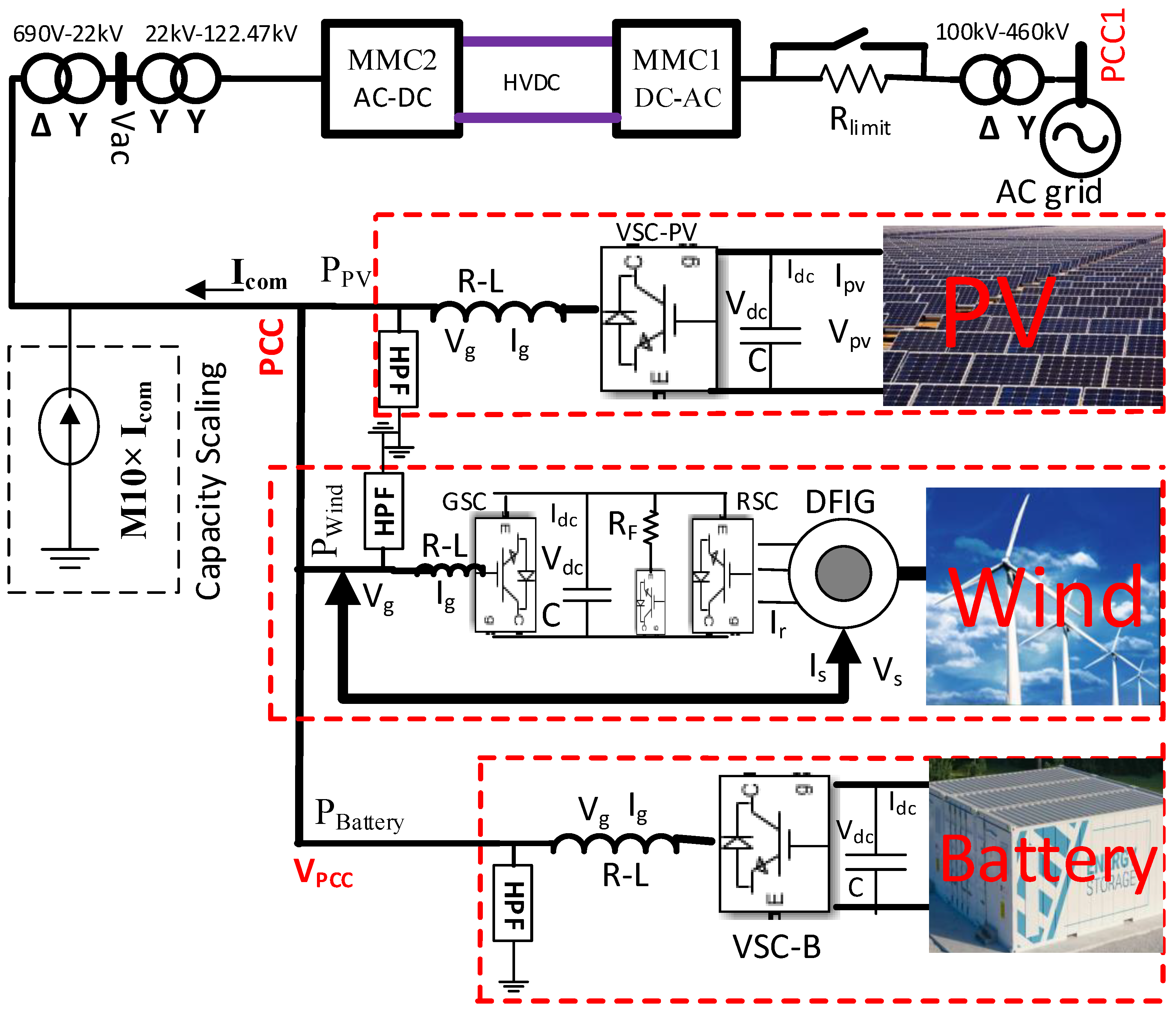
Figure 1. MMC-HVDC system with energy storage and renewable energy resources.
Sustainability 15 02626 g001
Figure 2. Electrical equivalent circuit of Min/Rincón-Mora model [66].
Sustainability 15 02626 g002
Figure 3. Equivalent electrical circuit of MMC1.
Sustainability 15 02626 g003
Figure 4. Outer and inner control loops of MMC.
Sustainability 15 02626 g004
Figure 5. The changes at different points of PV-wind-battery-connected MMC-HVDC network during LLLG fault at the PCC of MMC1 side AC grid (PCC1).
Sustainability 15 02626 g005
Figure 6. Control strategy for excess energy control of HVDC-link and power smoothing (a) MMC2 outer control (b) reference power of battery for the HVDC-link’s surplus energy control (c) power leveling during the change in weather condition (wind speed, solar radiation, and temperature) (d) charging and discharging control of battery.
Sustainability 15 02626 g006
Figure 7. Inner current control loop of battery.
Sustainability 15 02626 g007
Figure 8. RTDS-dSPACE hardware setups.
Sustainability 15 02626 g008
Figure 9. Real-time user interfaces in RTDS.
Sustainability 15 02626 g009
Figure 10. MMC1 controller in dSPACE interfaced with RTDS.
Sustainability 15 02626 g010
Figure 11. DBR-based traditional controller.
Sustainability 15 02626 g011
Figure 12. Traditional controller performance during low-voltage faults.
Sustainability 15 02626 g012
Figure 13. PCC1 voltage for the low-voltage LLLG fault duration.
Sustainability 15 02626 g013
Figure 14. Real power and reactive current of MMC1 during the event of an LLLG fault.
Sustainability 15 02626 g014
Figure 15. PCC voltage, real power change of wind, PV, and battery source, battery SOC, and HVDC-link voltage throughout the LLLG fault.
Sustainability 15 02626 g015
Figure 16. PCC1 voltage for the duration of the low-voltage LLG fault.
Sustainability 15 02626 g016
Figure 17. Real power and reactive current of MMC1 for the interval of LLG fault.
Sustainability 15 02626 g017
Figure 18. PCC voltage, real power change of wind, PV, and battery source, battery SOC, HVDC-link voltage throughout the LLG fault.
Sustainability 15 02626 g018
Figure 19. Solar irradiance, real power change of wind, PV, and battery source, battery SOC, and active power of the MMC1 during solar irradiance reduction.
Sustainability 15 02626 g019
Figure 20. Solar irradiance, real power change of wind, PV, and battery source, battery SOC, and the active power of the MMC1 during solar irradiance increase.
Sustainability 15 02626 g020
Figure 21. PV temperature, real power change of wind, PV, and battery source, battery SOC, and active power of the MMC1 during PV cell temperature increase.
Sustainability 15 02626 g021
Figure 22. PV temperature, real power change of wind, PV, and battery source, battery SOC, and active power of the MMC1 during PV cell temperature reduction.
Sustainability 15 02626 g022
Figure 23. Wind speed, real power change of wind, PV, and battery source, battery SOC, and active power of the MMC1 during wind speed reduction.
Sustainability 15 02626 g023
Figure 24. Wind speed, real power change of wind, PV, and battery source, battery SOC, and active power of the MMC1 during wind speed increase.
Sustainability 15 02626 g024
Figure 25. Solar irradiance and wind speed, real power change of wind, PV, and battery source, battery SOC, and active power of the MMC1 during solar irradiance and wind speed reduction.
Sustainability 15 02626 g025
Figure 26. Solar irradiance and wind speed, real power change of wind, PV, and battery source, battery SOC, and active power of the MMC1 during solar irradiance and wind speed increase.
Sustainability 15 02626 g026
Figure 27. Battery charging illustration.
Sustainability 15 02626 g027
Table 1. Technical specifications for one EssProTM Grid container [67].
ParameterValue
Discharge power1 MW0.5 MW
Maximum DC voltage1.2 kV1.2 kV
Battery current833.3 A416.7 A
Discharge time0.25 h0.25 h
Energy capacity0.25 MWh0.125 MWh
Table 2. PV module, wind turbine, DFIG generator, and converter data.
PV Module ParametersWind Turbine Parameters
QuantityValueQuantityValue
Cells per module 36Nominal wind speed12 m/s
Short circuit current3.35 ANominal generator speed, DFIG1.2 pu
Open circuit voltage21.7 VNominal turbine power 2 MW
Current at MPP3.05 ADFIG and controller parameters
Voltage at MPP17.4 VQuantityValue
Temperature coefficient of Isc0.065%/degreeStator voltage (L-L)690 V
Temperature coefficient of Voc−0.56%/degreeNominal frequency, f50 Hz
PV array parameterNominal power2.2 MVA
Series connected modules per string115Stator resistance, R s 1 mΩ
Parallel strings285Rotor resistance, R r 1.3 mΩ
Grid side VSC parameters for batteryInductance of stator, L s 2.55 mH
QuantityValueInductance of rotor, L r 2.56 mH
Nominal DC-link voltage2 kVMagnetizing inductance, L m 2.44 mH
Rated power2.2 MVAHigh pass filter (HPF) parameters
Resistance, R0.004 puFilter inductance, LF4.3 µH
Inductance, L0.15 puFilter capacitance, CF1.47 mF
PI3 ( 1 + 100 / s )   p u Filter resistance, RF0.054 Ω
Table 3. MMC and battery controller parameters.
ParametersValueParametersValue
Rated power200 MWC16 mF
Rated HVDC-link voltage200 kVCd100 µF
Rated AC voltage (L-L)100 kVSM/arm200
Nominal frequency50 HzDC line resistance per km1.39 mΩ
Reactor resistance, R0.002 puDC line inductance per km0.159 mH
Reactor inductance, L0.2 puDC line capacitance per km0.231 µF
ModulationNearest levelM1026
PI4 ( 4 + 100 / s )   p u Parameters of battery controller
PI70.6+6/s puBattery discharge power capacity4 MW
PI100.8+100/s puDuration15 min
PI80.6+6/s puPI51 ( 20 + 15 / s ) pu
AC grids’ short circuit ratio10PI52(3+10/s) pu
Number of cells in series in a stack325
Number of stacks in parallel834
Capacity of a single cell1.00 AH
Nominal cell voltage3.7 V
Disclaimer/Publisher’s Note: The statements, opinions and data contained in all publications are solely those of the individual author(s) and contributor(s) and not of MDPI and/or the editor(s). MDPI and/or the editor(s) disclaim responsibility for any injury to people or property resulting from any ideas, methods, instructions or products referred to in the content.