Abstract
The evolution of district heating networks is moving toward low temperatures in heat distribution with so called 4th generation networks. However, the lowest heat transfer fluid temperatures in district heating are achieved through ultra-low temperature networks, referred to as 5th generation district heating networks (5GDHNs). Low temperatures in heat distribution results in an extremely different configuration of 5GDHN compared to traditional district heating network, especially in the grid substation due to the inability to directly couple the grid with the buildings. This paper presents a detailed design of a 5th generation substation prototype, which is carried out to verify the proper operation and monitor the performance of this type of substation in a real case study. The prototype is fed by low-temperature waste heat, currently dissipated through evaporative towers, and will be built in the city of Brescia, Italy. The layout of the substation prototype, consisting of a bidirectional pumping system, a reversible water-to-water heat pump, an inertial thermal energy storage and a heat exchanger, is presented. An analysis is performed to figure out which refrigerant offers the best performance of the heat pump. In addition, fixed the refrigerant, the performance of the grid connected heat pump is found to be increased from 29.5% to 55.5% for both heating and cooling compared with a stand-alone air-to-water heat pump solution. Finally, the process flow diagram and the piping and instrumentation diagram of the substation are presented and commented.
1. Introduction
One of the most promising technologies in the heating sector for achieving the transition to more sustainable energy sources is district heating. The heating sector is responsible for about 50% of total energy consumption in Europe. The 75% of heating and cooling demand is covered by fossil fuels and only the 18% by renewable energy [1]. Therefore, in order to meet the European Green Deal agreement to reduce greenhouse gas emissions by at least 55% by 2030, compared to 1990 values, and to eliminate greenhouse gas emissions by 2050 [2], it is essential to change the primary energy sources used in the heating sector.
District heating relies on centralized thermal power generation to increase energy efficiency and reduce the use of fossil fuels [3], compared with independent heat generation at individual users. The heat produced in the centralized plant is distributed by a network, with pressurized water as the heat transfer fluid. District heating networks are typically fed by combined heat and power plants (CHP) to increase the efficiency of energy conversion.
As described by Lund et al. in [4], district heating networks were introduced in the United States in the 1880s to avoid the risk of explosion of domestic boilers. These first-generation networks (1GDHN) used steam above 100 °C as the transport fluid and were consequently characterized by high thermal losses, low efficiency, and high costs for piping and network components.
The second generation of district heating (2GDHN) was developed in the 1930s and it replaced steam with pressurized water as the heat transfer fluid, at temperatures mostly above 100 °C, allowing increased efficiency and the use of CHP plants.
Due to the two oil crises, the first in 1973 and the second in 1979, and the intention to convert CHP plants from oil to different fuels, such as biomass, coal, and waste, third-generation district heating networks (3GDHN) were introduced in the 1970–1980 decade, with pressurized water at temperatures below 100 °C as the heat transfer fluid. This allowed further increases in efficiency and reductions in primary energy consumption; in addition, renewable energies, particularly geothermal and solar thermal collectors, began to be used in some cases. The third generation also allowed other important changes, such as the use of prefabricated and pre-insulated pipes and compact substations.
The subsequent evolution in recent years toward fourth-generation networks, 4GDHN, has been characterized by a further decrease in the temperature of water in the network, below 50–70 °C [4]. 4GDHNs represent the modern district heating networks and enable better resource management by increasing the efficiency of heat distribution, integration of renewable energy, and utilization of thermal waste from industrial processes. The fourth generation thus participates in achieving the goals that the European Union has set for the future in the energy sector and in the areas of digitization, electrification, decarbonization, urbanization, and combating climate change.
At the same time as 4GDHNs, networks of a different type, called either fifth generation (5GDHN) or ultra-low temperature district heating networks, are also being developed [5,6,7]. They use water at temperatures close to room temperature, or ground temperature, with values below 30 °C [8] as the heat transfer fluid, and for this reason they are also called neutral-temperature networks [9].
5GDHNs can be fed by natural low-temperature heat sources, but also by all waste heat from industrial processes, even the heat normally dissipated by evaporative towers, as there are no other recovery alternatives. Natural sources can be low-temperature shallow geothermal energy. Unlike deep geothermal energy, which uses the heat derived from the decay of radioactive elements, shallow geothermal energy is due to the storage of thermal energy from the sun. The soil is able to maintain a constant value through the year from a depth of 10–15 m down, thanks to the thermal inertia of the ground. García-Céspedes et al. [10] conducted a review on the use of shallow geothermal energy in the 5GDHN. Soil and groundwater can also be used to store low-temperature thermal energy through seasonal thermal energy storages, such as boreholes and aquifers (see for example Meibodi et al. [11]). In addition, 5GDHNs can be fed by low temperature heat from sea, lake, and river water or sewage water, which are considered “ambient energy” under EU Directive 2018/2001 [12]. Natural sources with higher temperatures compared with shallow geothermal energy, ambient energy or those that characterise heat distribution in 5GDHNs are solar thermal collectors. Therefore, the temperature of the heat produced by solar thermal collectors must be reduced to the temperature required by the grid. Outside air can also be used as a thermal reservoir from which heat can be transferred to the grid through a centralised air-to-water heat pump.
Buffa et al. [8] describes the most important 5GDHNs installed in Europe: Geneve-Lac-Nation e LaTour-de-Peilz use water from Lake Geneva, whereas in Ohrberg (Germany) is used thermal energy from the Wesen River. In Leuven (Belgium), the Janseniushof project uses the Dijle River and geothermal wells [13]. Saas Fee and REKA village are examples of installing hybrid solar solution through photovoltaic thermal panels [8]. Waste heat from local dairies with a temperature range from 25 to 35 °C is used in Aurich and Herford (Germany), and heat at temperatures from 8 to 18 °C by a chemical industry is used in the Visp-West district in Switzerland [8]. Moreover, data centers and chillers are used as sources of low temperature thermal energy in the Familienheimgenossenschaft’s Swiss 5th generation system, whereas abandoned coal mines are used in Herleen (The Netherlands) since 2008 [14].
The fact that in the 5GDHNs the temperature of the supply line is not sufficient to cover the heat demand of the users has several consequences. First, it is necessary to install a heat pump in order to supply the required heat to the user. This makes it possible to both cover the demand of building with different heating system technologies and satisfy the user’s heating and cooling needs simultaneously. This last feature is particularly important because buildings in Europe are expected to have a 20–30% reduction in heating demand and a tripling of cooling demand by 2050, compared to 2006 values [15].
District cooling networks have also been developed since the early 19th century: the first generation involved centralized condensers and decentralized evaporators in user substations and refrigerants as cooling distribution fluids; since the development of the second generation, which was developed in the 1960s, centralized systems have been replaced by decentralized mechanical chillers and refrigerants have been replaced by chilled water; and with the third generation, absorption chillers and cold accumulators also came into use. Nowadays, 5GDHNs are considered a sustainable way to cover the cooling demand in the building sector.
The dual configuration of the 5GDHNs, gives network users a new role. In fact, users with heating demand absorb heat from the grid, but those with cooling demand provide heat to the grid. In this way, they are not just consumers, but consumers and producers, and are called prosumers [16]. In addition, decentralized heat pumps enable the connection between power grids and district heating networks to create smart thermal grids, and there is the possibility of powering heat pumps through electricity generated in users’ homes from renewable energy. The performance of a heat pump in a 5GDHN and the influence of grid temperature on coefficient of performance (COP) are presented by Reiners et al. [5].
Another feature of the 5GDHNs is the ability to store heat in the grid, as studied by Quirosa et al. [6] for a 5GDHN located in southern Spain. The base load of this network is covered by centralised air-to-water heat pumps, which exploit solar photovoltaic. Thus, the grid operates as a thermal energy storage for renewable energy, for both heating and cooling. In the case of cooling, the substation configuration allows direct cooling through a heat exchanger if the grid temperature is low enough not to require heat pump work. A similar 5GDHN is described by Wirtz et al. [17], who created a mathematical model to optimise the design and sizing of all energy conversion units in the grid, both in buildings and energy hubs. They demonstrated a 42% reduction in energy consumption and 56% reduction in CO emissions with 5GDHN compared to individual heating and cooling systems by comparing thermodynamic, economic, and environmental parameters.
The low-temperature heat distribution and the smaller temperature gradient between supply and return lines result in higher volumetric flow rates, with a 1.5-fold increase in pipes diameter compared to 3GDHN lines [6], and higher pumping costs.
A particularly critical aspect of the 5GDHNs is the complexity of the substations at the users’ site, which must include a heat pump to replace the heat exchanger of the previous generation substation, and a decentralized pumping system. The heat pump can be “simple” or reversible according to the heat demand of the building, while the presence of the decentralized pumping system depends on the pumping solution adopted for the 5th generation network. In traditional district heating, the pumping system is centralized and located in the same plant, where heat is also generated, while in 5GDHNs it may be convenient to integrate hydraulic pumps in the substations. This critical issue also emerges in a techno-economic comparison between 4GDHNs and 5GDHNs by Gudmundsson et al. [18], which shows that the economic advantage of a network without insulated pipes in the case of a 5GDHN cannot counterbalance the high investment and operating costs of the decentralised heat pump of the end users. In fact, the advantages of the economy of scale in centralised heat generation and simpler building interface unit result in a lower levelised cost of energy for 4GDHNs than for 5GDHNs.
The main feature of the different district heating generations and the innovations of the 5th generation are summarised in the Table 1.

Table 1.
Development of district heating across generations (Sources: [4,8,19]).
This paper aims to fill the lack in the literature of a detailed description of the substation in 5GDHNs, which result to be one of the most critical aspects for the new generation networks, but important for enabling the new role of prosumers. The main objective of this paper is to present the design and the configuration of a prototype substation, which can be replicated for the development of a 5GDHN in the city of Brescia (Italy) next to the existing district heating network. The prototype substation will be built and monitored to verify its proper operation and evaluate its performance. Therefore, the local utility company A2A Calore & Servizi could also improve its know-how on 5GDHN and, in particular, prosumer substations. This will give the company an advantage in building 5GDHNs and prosumer substations in the future.
Specifically, Section 2 presents the real case study and the heat pump selection method. Section 3 analyzes the influence of refrigerant type on heat pump performance, and compares the differences between connecting to a 5GDHN and a stand-alone solution consisting of an air-to-water heat pump. Section 3 also shows the result of substation design with piping and instrumentation diagram (P&ID). The conclusions are reported in Section 4.
2. Materials and Methods
2.1. The A2A North Power Plant in Brescia
The design concerns a prototype 5GDHN substation to be installed in the city of Brescia to study its performances. The prototype will be installed in the city of Brescia. Brescia, located in northern Italy, has an extensive traditional district heating network made by more than 670 km of double pipes [20], managed by the local utility company A2A Calore & Servizi. The total heat produced for district heating is about 1.3 TWh per year, generated by waste-to-energy plant, a CHP plant and natural gas boilers used to cover peak demand from the grid [20]. The district heating network of Brescia can be classified as a third generation one, but temperatures can exceed 100 °C during the coldest periods of winter, especially in sections of the network close to the heat generation plants. In line with the transition presented in the introduction, A2A Calore & Servizi intends to move towards a lower temperature in grid heat distribution in order to approach a 4GDHN. Some steps have already been taken to move to a more energy sustainable network, through reducing fossil fuels penetration, using industrial waste heat, and some tests to increase grid efficiency with temperature reduction. With the TEMPO (Temperature Optimisation for Low Temperature District heating across Europe) project [21], the temperature of the supply line in a subgrid of the district heating network has been decreased to 80 °C in order to check the feasibility of a transition to 4th generation for Brescia’s district heating network. In addition, to decrease the utilisation of natural gas boilers and increase the use of waste-to-energy plant, thermal energy storages have been installed in the city, the first with a capacity of 5000 of water, the other two with a capacity of 2200 each. They feature an innovative water supply system, that was designed by A2A Calore & Servizi in collaboration with the University of Brescia [22]. A first performance analysis is reported in the study of Pilotelli et al. [23]. The main source of heat for district heating is covered by the waste-to-energy plant, which generates about 70% of the total heat distributed by the grid (datum refers to 2021–2022 heating season). Recently, waste heat produced by two steel mills in the city has been recovered through the district heating network. With the project Smart Grid Pilot: Banco Energetico [24] in fact, a pilot plant was built on the pipe-to-pipe flue gas exiting the melting furnace to make it possible to feed waste heat into the district heating network. Waste heat from steel mills covers 1.8% of the total heat supplied to the grid in the 2021–2022 heating season. With the same Smart Grid Pilot: Banco Energetico project, a preliminar analysis to evaluate the effect of district heating temperature reduction on the end users was performed [25].
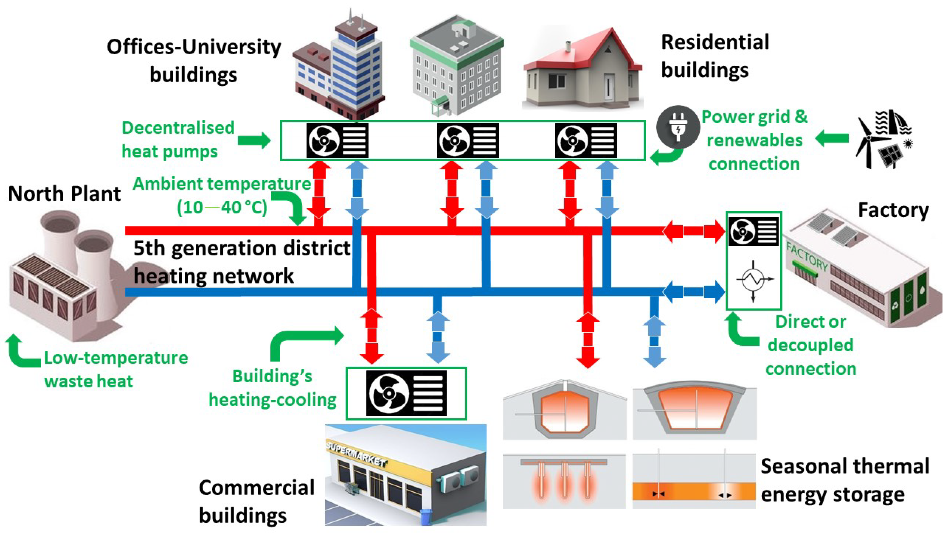
In addition to the optimisation processes of the traditional district heating network in Brescia, A2A Calore & Servizi is evaluating the implementation of a 5GDHN to recover low-temperature waste heat generated in A2A Calore & Servizi’s North Plant. Residential and office buildings, not connected to the traditional district heating network of Brescia, could be connected to this 5GDHN, as well as other prosumers, such as commercial buildings and factories, that generate low-temperature waste heat throughout the year. Another heat source for the 5GDHN could be the return line of the traditional district heating network. Moreover, seasonal thermal energy storage, particularly aquifers, boreholes or pit storages, could also be connected to the grid. Figure 1 shows the pattern of the new 5GDHN with different types of prosumers connected.

Figure 1.
Representation of the 5GDHN that is to be developed in Brescia.
Low-temperature waste heat available at the North Plant is generated by centralised chillers feeding a district cooling network, which covers a year round cooling demand of the nearby hospital and the summer cooling demand of some university buildings.
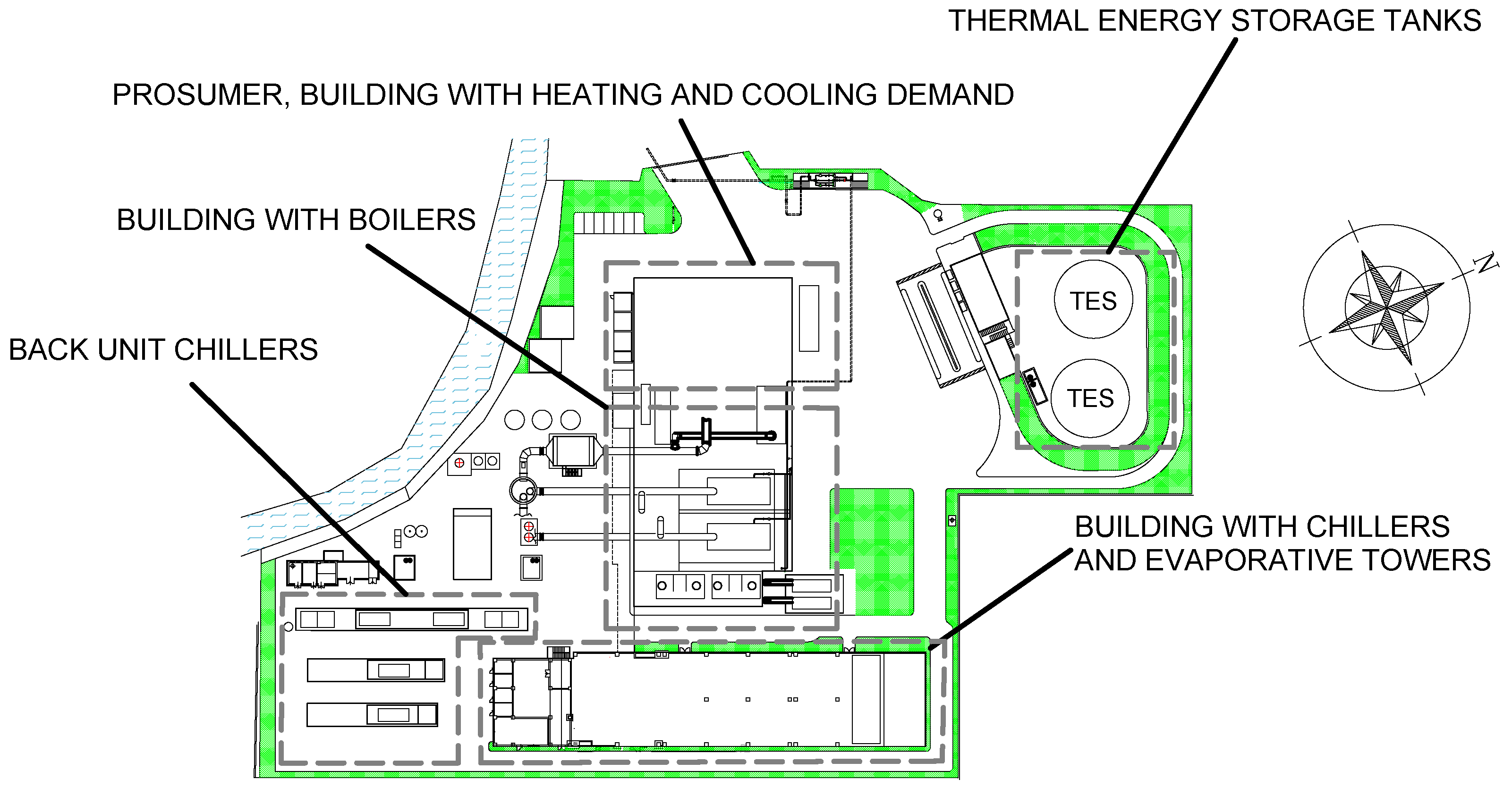
The North Plant houses, in addition to the chillers, the natural gas boilers for the traditional district heating network and two thermal energy storage tanks, as shown in Figure 2.
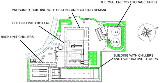
Figure 2.
Map of the North Plant, with the prosumer, the building where prototype substation will be installed and the building housing chillers and evaporative towers.
Some tests are needed before the realization of a real 5GDHN, especially on the 5th generation substation, which is very different and more complex with respect to the traditional one. For this reason, the development of a 5th generation substation prototype is underway.
The idea is to test the prototype substation through a pilot 5GDHN. To recreate a 5GDHN for the testing phase, the waste heat produced by the centralised chillers, currently dissipated through evaporative towers, will be used. The waste heat base load, the energy source, is larger than 1.5 MW throughout the year.
The North Power Plant itself has both heating and cooling requirements, for the building where the offices and control rooms are located (see Figure 2), which are currently covered by the traditional district heating network. Therefore, the substation prototype will be installed at the North Plant in order to use this heating and cooling demand as prosumer to test the 5GDHN substation that will replace the traditional one.
Another important feature in the prototype design is to consider that the configuration will be replicated on a large scale, given the intention of A2A Calore & Servizi to develop a real 5GDHNs in the near future.
2.2. Analysis of Energy Source from Evaporative Towers
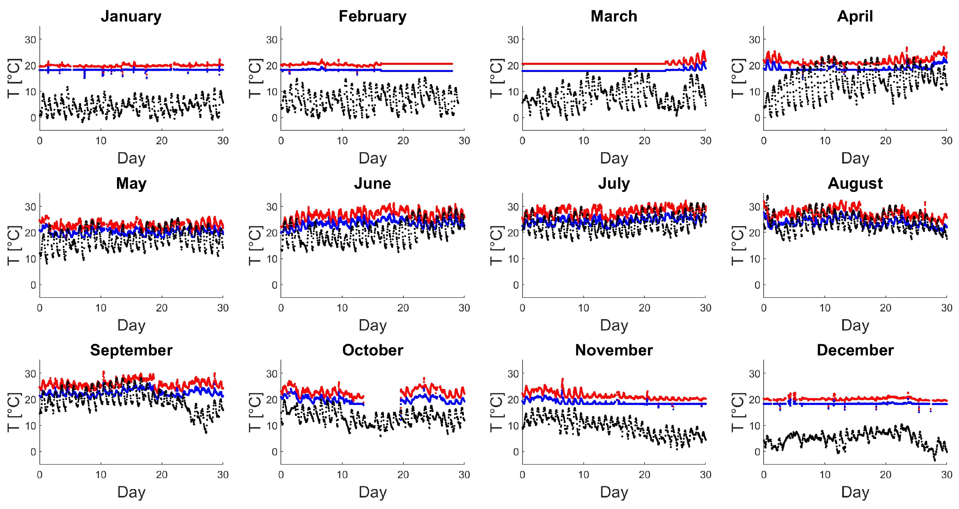
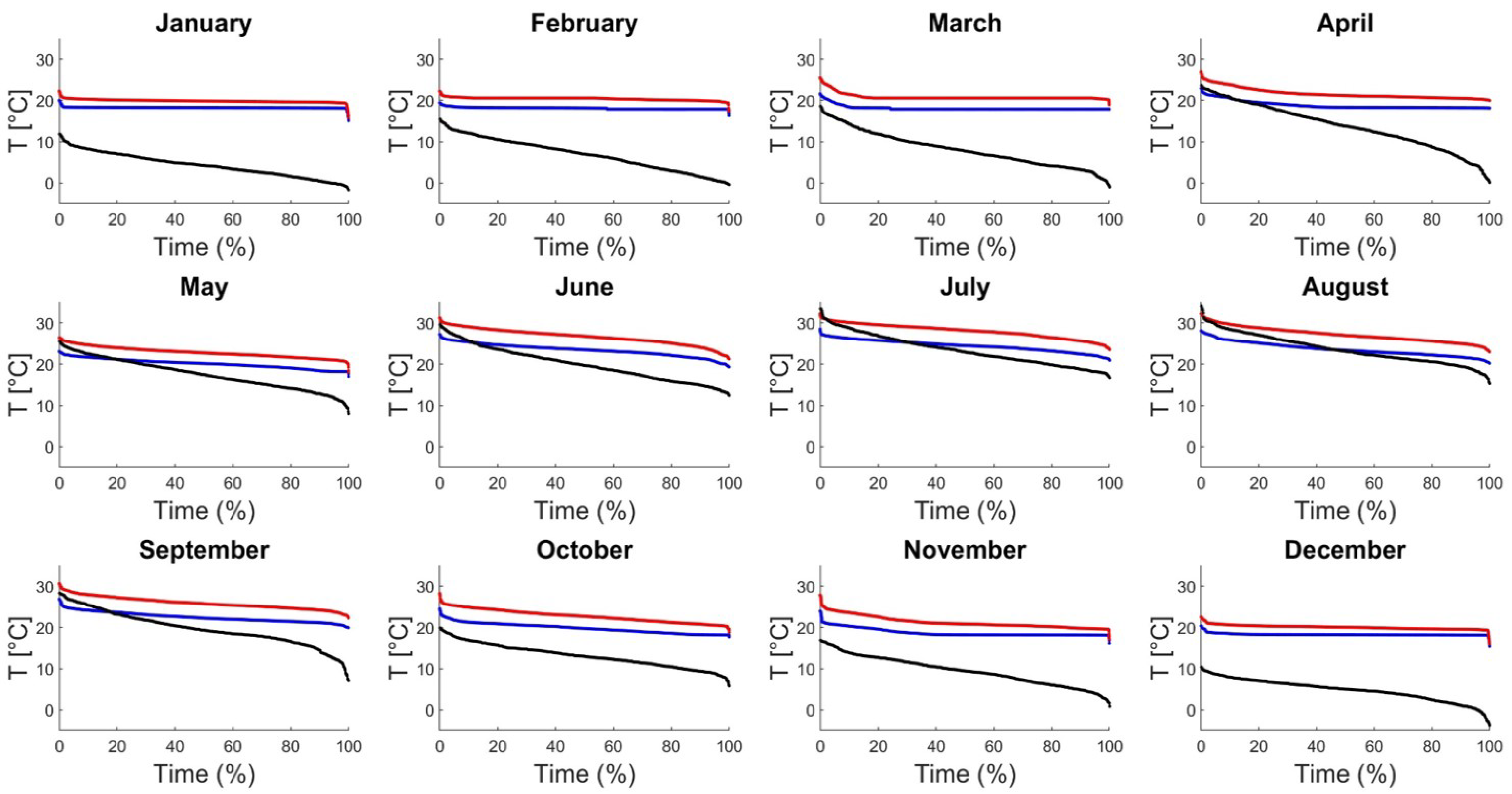
In this subsection, the heat source for the substation prototype is analysed, as well as the temperatures of the evaporative towers circuit. This is made possible by measurements taken continuously for one year by means of Pt100 temperature sensors installed in the evaporative towers circuit. Temperature sensors are placed in the supply line of the evaporative towers right at the outlet of the chillers to the evaporative towers. Moreover, temperature sensors are also installed in the line connecting the outlet of the evaporative towers to the inlet of the chillers. These data were provided by the utility company A2A Calore & Servizi in the form of a spreadsheet file and were post-processed with MATLAB. The summary of these measurements is shown in Figure 3 for the various months, in temporal order. In Figure 3, the red dots represent the measurements of the supply line of the evaporative towers circuit, while the blue dots represent the measurements referring to the return line. Instead, Figure 4 shows the same data rearranged in decreasing order to obtain the temperature duration curves for different months, with the red and blue lines representing the temperatures of the evaporative towers circuit. Measures on some days in February and March are affected by acquisition errors (constant values), while on some central days in October, the flow rate of the evaporative towers circuit was null, so the temperature measurements are invalid. For all other days in the year 2020, temperature values are reliable. The measurement frequency is one measure every 10 minutes.
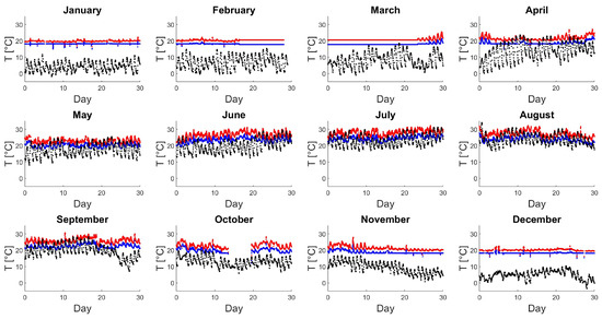
Figure 3.
Evaporative towers: inlet temperature of the supply line (red dots), and outlet temperature of the return line (blue dots). Outdoor air temperature for the city of Brescia (black dots).
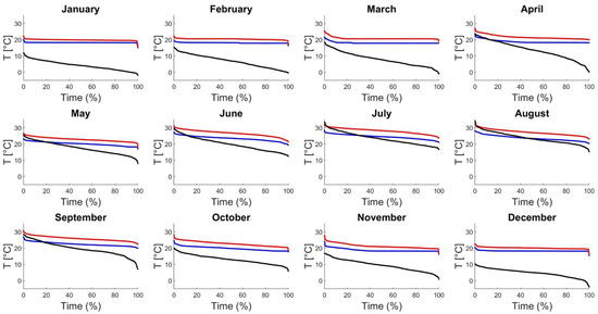
Figure 4.
Red and blue lines: temperature duration curve of the supply and return line of the evaporative towers. Black lines: outdoor air temperature duration curve for the city of Brescia.
2.3. Analysis of Thermal Demand
The power plant building requiring heating is supplied by a thermo-hydraulic circuit consisting of fancoils. To cover the heating requirement, the temperature of the thermo-hydraulic circuit must be 65 °C in the supply line and 60 °C in the return line. For the cooling demand, the supply line must have a temperature of 6 °C and 11 °C in the return line. The substation does not cover domestic hot-water demand, because the building houses offices and a control room.
2.4. Features of 5GDHN and Prototype Substation
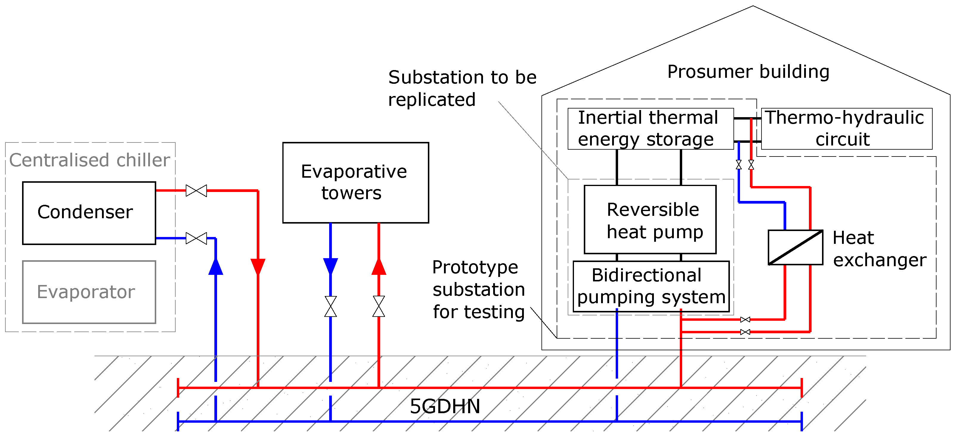
The simplified scheme of the connection between the centralised chillers, the evaporative towers and the substation with the 5GDHN is shown in Figure 5. The low-temperature waste heat produced by the centralised chillers will be used to power the pilot 5GDHN. The evaporative towers absorb heat from the grid dissipating the excess heat. Finally, the building where the prototype substation will be installed is the prosumer, and has both heating and cooling demand. The chillers and the evaporative towers can represent the behaviour of single demand users in a real 5GDHN.
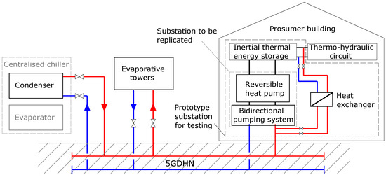
Figure 5.
Scheme of prototype substation, 5GDHN and evaporative towers circuit.
The prototype substation consists of a:
- Reversible heat pump;
- Bidirectional pumping system;
- Inertial thermal energy storage;
- Heat exchanger.
The inertial thermal energy storage allows to decouple heating and cooling demand from the heat pump; this enables higher performance compared with direct coupling of the heat pump with the thermo-hydraulic circuit. In the future, the installation of inertial storages in the substations will depend on the specific case, the heating demand of the building, and the characteristic of the heat pump. The heat exchanger is peculiar of the prototype substation because the intention is to test the performance of the heat pump over a wider temperature range than that of the pilot 5GDHN and will not be incorporated in future 5GDHN substations. In the prototype, the temperature of the 5GDHN will be rise up to 40 °C, at the inlet of the heat pump evaporator, using heat from the thermo-hydraulic circuit. The reason for monitoring heat pump performance over a wider temperature range is due to the possibility of using different low temperature heat sources to feed a 5GDHN, even with higher temperature than those of the evaporative towers circuit. The upper limit of heat sources temperature has been set at 40 °C, as this temperature is believed to be the maximum compatible with a 5GDHN. In Brescia, this temperature can be reach through the return line of the traditional district heating.
One feature of the substation is the decentralised pumping system. In 4GDHN, the pressure on the network is regulated by the centralised pumping system, with higher pressure in the supply line than in the return line to counteract pressure losses. Moreover, the pressure of the supply line increases with the heat demand of the grid. The idea of the decentralised pumping system is completely different: all substations, through a hydraulic pump, cover their heat demand by pumping heat transfer fluid from the grid to the heat pump. Specifically, in heating mode, heat is transferred from the grid to the heat pump. In contrast, in cooling mode, the heat pump operates as a chiller and heat is dissipated from the heat pump onto the network.
The operation just described can be performed by a system consisting of a pair of three-way valves placed between the network and the hydraulic pump. In this way, there is no upper pressure line as in the conventional network, but a higher temperature line (supply line) and a lower temperature line (return line). The pressure result is determined by the decentralised pumping system.
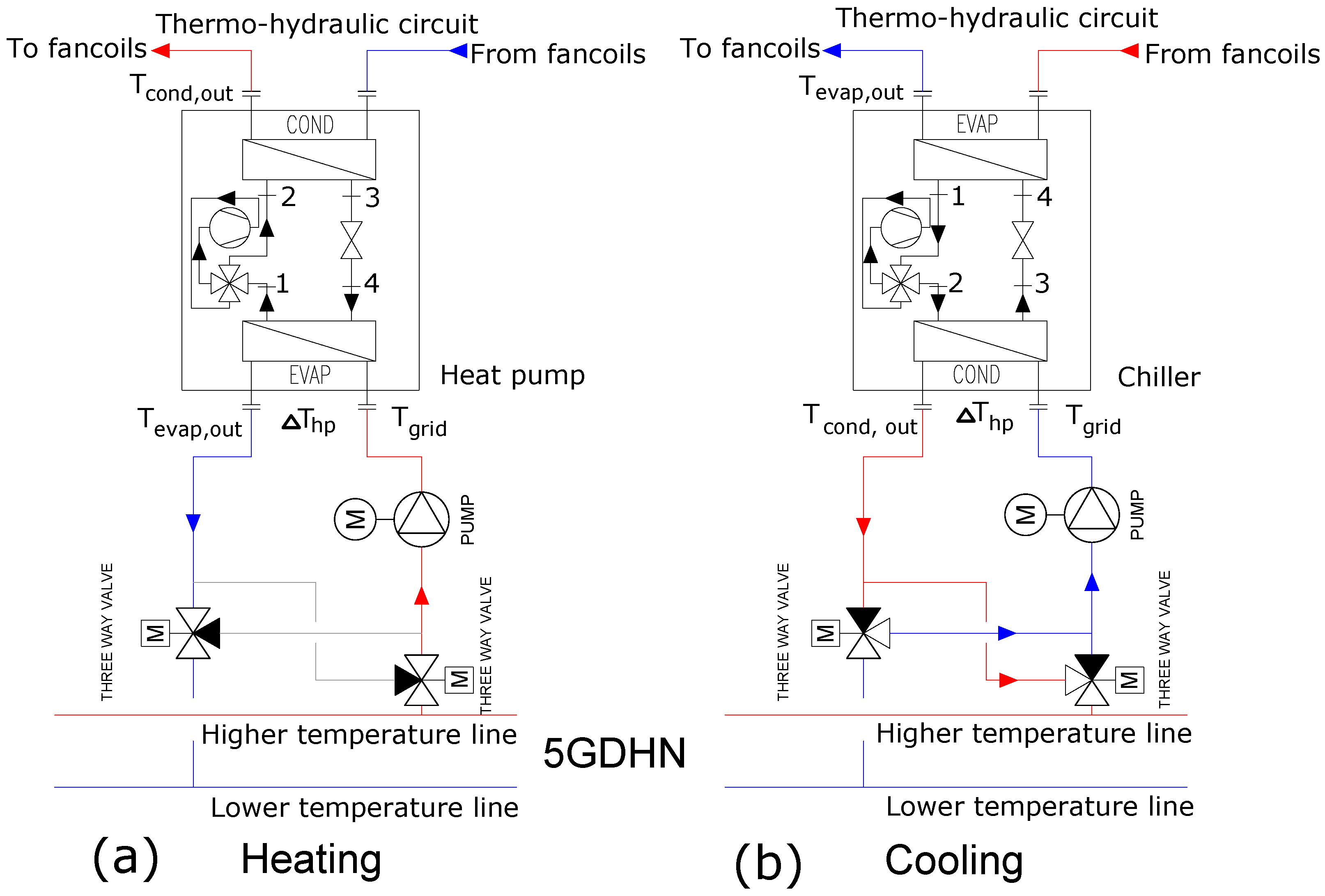
The operation of the bidirectional pumping system based on a couple of three-way valves and selected for the substation prototype is illustrated in Figure 6, where the reversible heat pump is also represented in both heating and cooling configurations. In the same Figure 6, temperature symbols are shown for the performance analysis of the substation prototype presented in the Section 2.5.
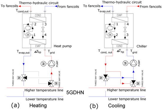
Figure 6.
Prosumer substation layout composed by: decentralised pumping system and heat pump. (a) Heating configuration. (b) Cooling configuration. Numbers 1 to 4 represent the refrigerant conditions at the evaporator inlet and outlet (4 and 1 respectively) and at the condensator inlet and outlet (2 and 3 respectively).
In the substation, the bidirectional pumping system enables efficient coupling of the reversible heat pump and the two-pipe 5GDHN. The left side of Figure 6 shows the heating configuration: in this case, the heat transfer fluid is pumped from the high temperature line of the network to the heat pump evaporator and returned to the low temperature line of the network. While heat is given to the carrier fluid of the thermo-hydraulic circuit through the heat pump condenser. The cooling configuration is presented on the right. In this case, the heat transfer fluid is drawn from the low-temperature line of the grid and heated by the heat pump condenser, which functions as a chiller. The heat transfer fluid is then rejected to the high-temperature grid line. The carrier fluid in the thermo-hydraulic circuit is cooled through the chiller evaporator, which transfers heat to the refrigerant of the chiller. To switch from heating to cooling configuration, the three-way valves reverse their position and the heat pump operates as a chiller. This is made possible by a four-way valve, located inside the heat pump, which decouples the evaporator and condenser from the compressor.
The bidirectional pumping system can also be achieved with another control logic, presented by Licklederer et al. [27]. In this case, the high temperature piping (supply line) also has higher pressure with respect to the low-temperature piping (return line). The pumping system consists of a motorized two-way valve and a variable speed hydraulic pump.
In any case, both pumping system configurations create a passive operation of the 5GDHN, as described by Zeh et al. [19], because the circulation of the carrier fluid in the network is realised only by the feed pumps integrated in the grid substations.
The decentralised pumping system based on the three-way valves is preferable to the other, which consists of a single two-way valve, because it does not require a pressure difference between the high-temperature line and the low-temperature line. Therefore, the pressure in the piping results only from the demand of substations.
2.5. Features of the Reversible Heat Pump
The decentralised heat pumps in 5GDHN substations are water-to-water heat pumps, and the grid is used as a thermal reservoir.
The (COP), defined as the heat power supplied by the condenser divided by the electrical power absorbed by the compressor, is used to monitor the performance of the heat pump in the heating configuration. When the heat pump operates as a chiller, the energy efficiency ratio (EER), defined as the thermal power absorbed by the evaporator divided by the electrical power absorbed by the compressor, describes the efficiency of the chiller. The heat pump of the substation prototype operates between the evaporative towers circuit temperature and the temperature of the thermo-hydraulic circuit. Therefore, both COP and EER are a function of these temperatures. To estimate the performance of the heat pump and which is the best refrigerant in this temperature range, the thermodynamic cycle has been analysed with several simplified assumption. In what follows, subscripts 1, 2, 3, and 4 will refer to the refrigerant inlet and outlet of condenser and evaporator, in accordance with Figure 6.
- COP and EER are calculated as the ratio of the heat and electrical power evaluated as the enthalpy difference in the condenser (or evaporator) and compressor, using the thermodynamic properties of the heat pump refrigerant.
- The temperatures and at the condenser and evaporator outlet are given in Table 2, both for heating and cooling configurations, and refer to Figure 6. On the thermo-hydraulic circuit side, and are set to meet the requirements of fancoils. On the 5GDHN side, is defined from the average values of the July evaporative towers circuit temperatures () with an increase in the value of due to the heat transferred from the heat pump condenser. is defined by the average values of the evaporative towers circuit temperatures of January () with a decrease in value of due to the heat transferred to the heat pump evaporator. To calculate the temperature differences at the condenser and evaporator of the heat pump, , the size of the network piping has been fixed along with the size of the heat pump. The detailed description of the network piping, derived from the sizing procedure, is described and commented upon in the Section 3.3, while the size of the heat pump has been estimated by the company A2A Calore & Servizi from the heat load of the building. In the same Table 2 are also added the heat flux exchanged between the grid and the heat pump, , the grid mass flow rate , the temperature difference due to the heat exchanged with the heat pump for both heating and cooling configurations, and the grid temperature of January for heating and July for cooling.
Table 2. Design points for the real case study.
- At point 1, the evaporator outlet, the refrigerant is in the saturated vapour state at the evaporation temperature, derived from the difference between and the heat exchanger lift , typically on the order of 2 K [9].
- At point 3, the outlet of the condenser, the refrigerant is in a saturated liquid state at the condensation temperature, derived from the sum of the and the heat exchanger lift, also with value of 2 K.
- At point 2, the compressor outlet, the refrigerant is in a superheated vapour state. To account for the non-ideality of the compression phase, the isoentropic efficiency of the compressor is derived from the curve reported by Pascalis et al. [28]. This applies to a scroll compressor, which is used in most cases in heat pumps on the market with a thermal size of about 100 kW. In this way, it is possible to derive the compressor efficiency value as a function of the pressure gap between evaporating and condensing pressure levels.
- The process through the expansion valve is isenthalpic, point 4 is the outlet of the expansion valve.
- Pressure drops are not taken into account in this model.
The CoolProp C++ library, through MATLAB, is used to calculate the thermodynamic properties of different heat pump refrigerants. This make it is possible to compare these fluids and their impact on heat pump performance.
3. Results and Discussion
3.1. Choice of the Heat Pump Refrigerant
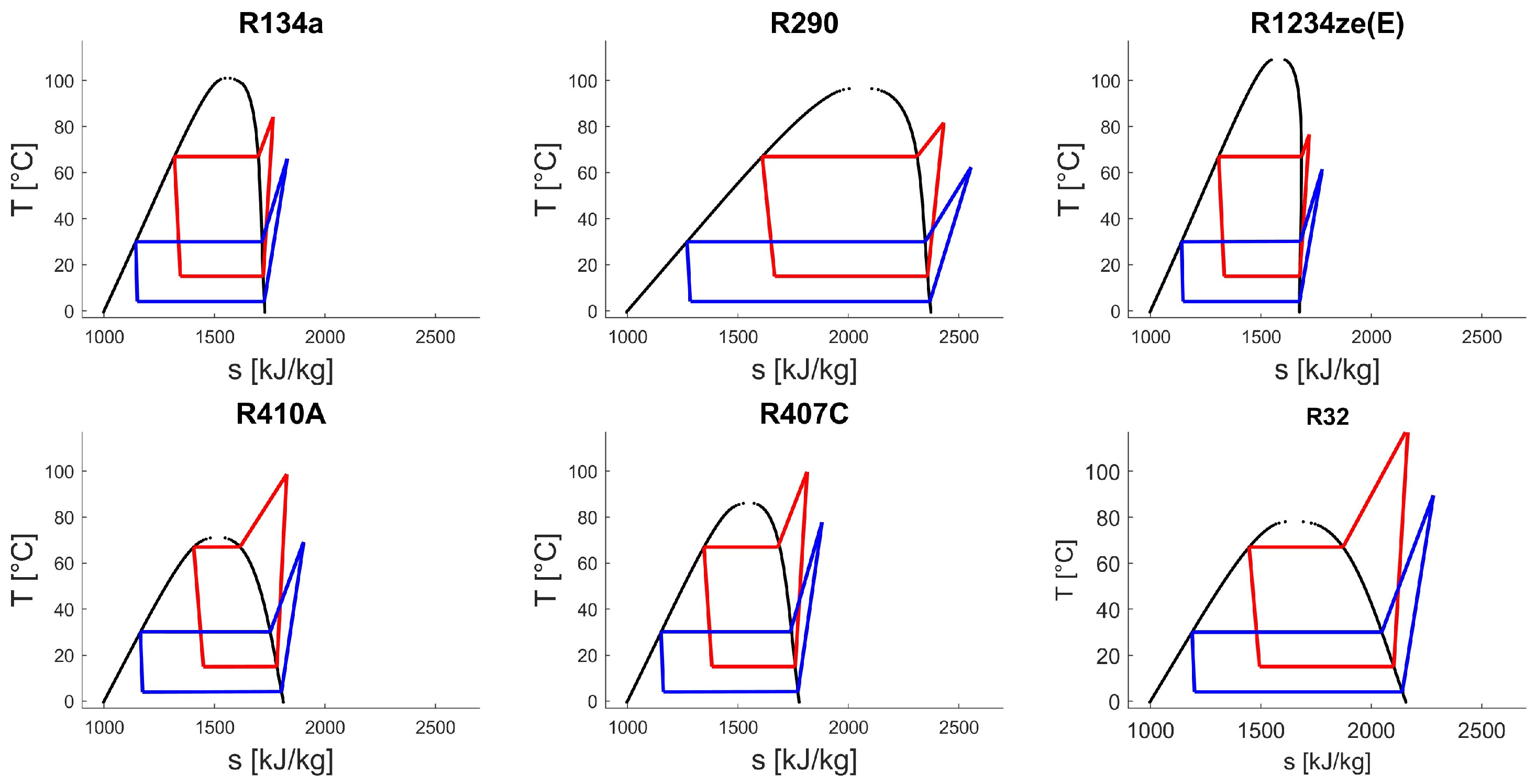
To enable a comparison of different refrigerants, six of the most common refrigerants used in heat pumps have been analysed. The temperature–entropy and pressure–enthalpy diagrams for these six different refrigerants are shown in Figure 7 and in Figure 8, respectively. In the same figures, thermodynamic cycles for heating and cooling are represented with red and blue lines. The values of COP and EER, as explained in Section 2.5 for all the refrigerants analysed, along with the electrical power absorbed by the heat pump compressor ( and ) are reported in Table 3, with the addition of the global warming potential (GWP). In this way, it is possible to figure out which refrigerant obtains the best performances for the substation. Higher performances in heating configuration are more relevant with respect to cooling configuration due to the position of the plant, located in the North of Italy, where heating demand is higher than cooling demand. Therefore, to minimise energy consumption, higher COP values result to have a greater influence with respect to EER values. The analysis obtained by fixing the shows that the best performing refrigerants are R290, R134a, and R1234ze.
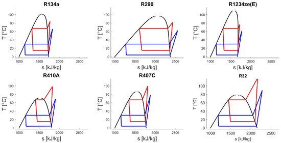
Figure 7.
Comparison of heat pump thermodynamic cycle for heating (red lines) and cooling (blue lines) between different refrigerants for the temperature-entropy plane.
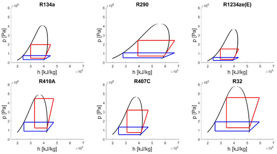
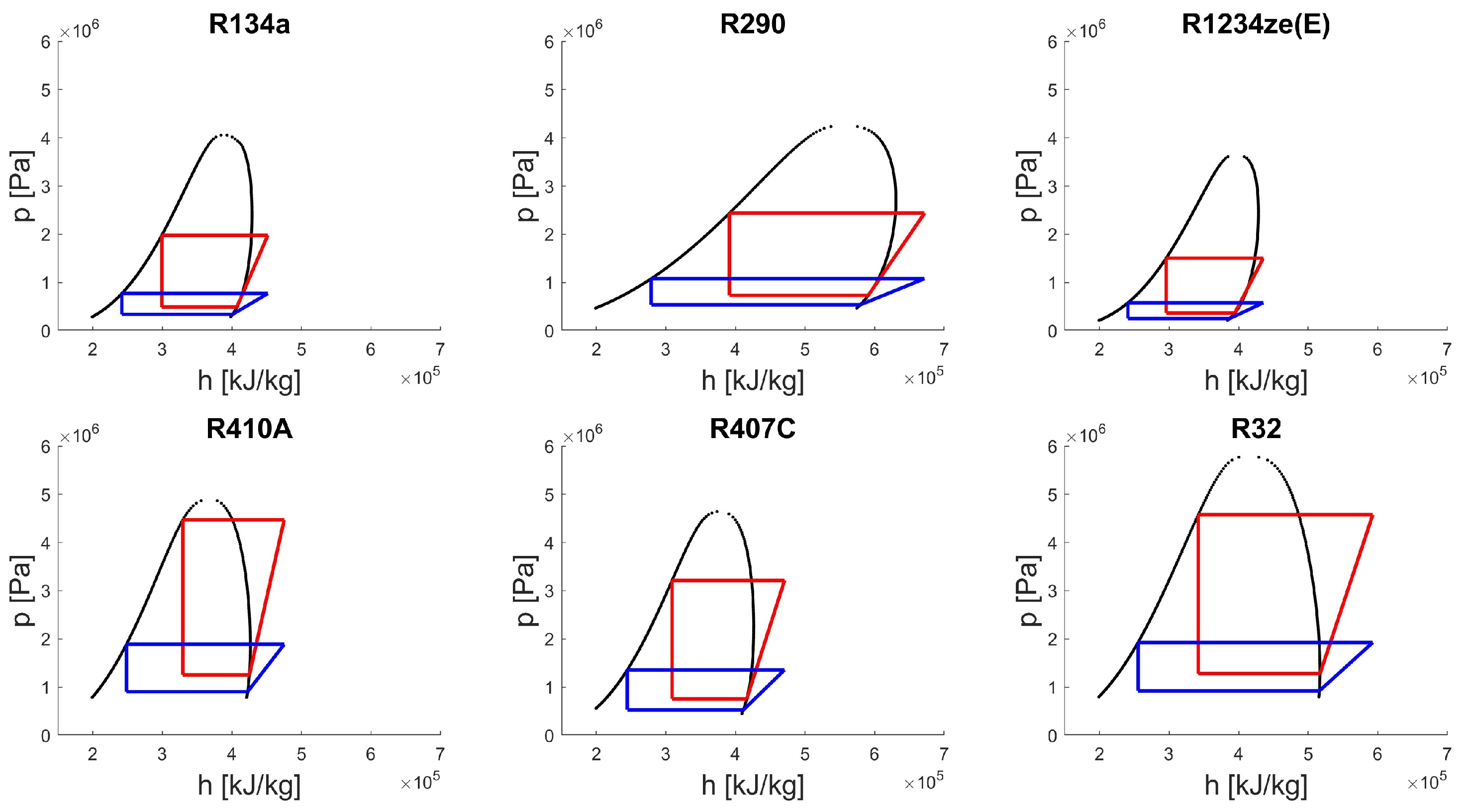
Figure 8.
Comparison of heat pump thermodynamic cycle for heating (red lines) and cooling (blue lines) between different refrigerants for pressure–enthalpy plane.
Table 3.
Comparison of COP, , EER, and GWP among different refrigerants.
An additional issue is the performance of the substation for different inlet temperatures of the heat pump evaporator, higher than those of the evaporative towers circuit, up to 40 °C. In the substation prototype, 40 °C will be reached at the inlet of the heat pump evaporator through the heat exchanger located in the substation. Therefore, a further analysis for selecting the most convenient refrigerant concerns the performance obtained with a heat pump evaporator inlet temperature in the range between 16 and 40 °C. The result of this analysis can be seen in Figure 9, where COP is represented as a function of heat pump evaporator inlet temperature, for different refrigerants.
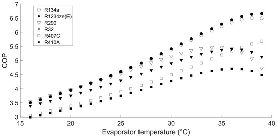
Figure 9.
Comparison of COP values for the six different refrigerants as a function of different evaporator temperature.
For all these reasons, for the prototype substation, it is better to choose a heat pump using R134a or R1234ze as the refrigerant, because they have a high performance even when the evaporator temperature exceeds 25 °C. While R290, propane, has the advantage of having a low value of GWP, being a natural substance and shows the highest performance at heat pump inlet temperatures below 25 °C, so this refrigerant can be used for the substation that will be replicated but not for the prototype, which requires evaporator inlet temperatures up to 40 °C. The latest analysis, in particular, shows that R134a has the best performance, but with a high value of GWP, so R1234ze seems to be an optimal alternative solution to R134a due to the advantage of having a low GWP value. However, the difficulty of finding a reversible water-to-water heat pump of about 100 kW thermal power with R1234ze on the market led to the selection for the prototype of a heat pump with R134a as refrigerant, which provides the best performance but has higher values of GWP.
Future restriction on the refrigerants will likely lead to the banning of R134a in heat pumps as well. Therefore, it will be possible for future 5GDHN substations to use heat pumps with R1234ze with performance close to that of R134a.
3.2. Comparison between Grid Connected and Stand-Alone Heat Pump
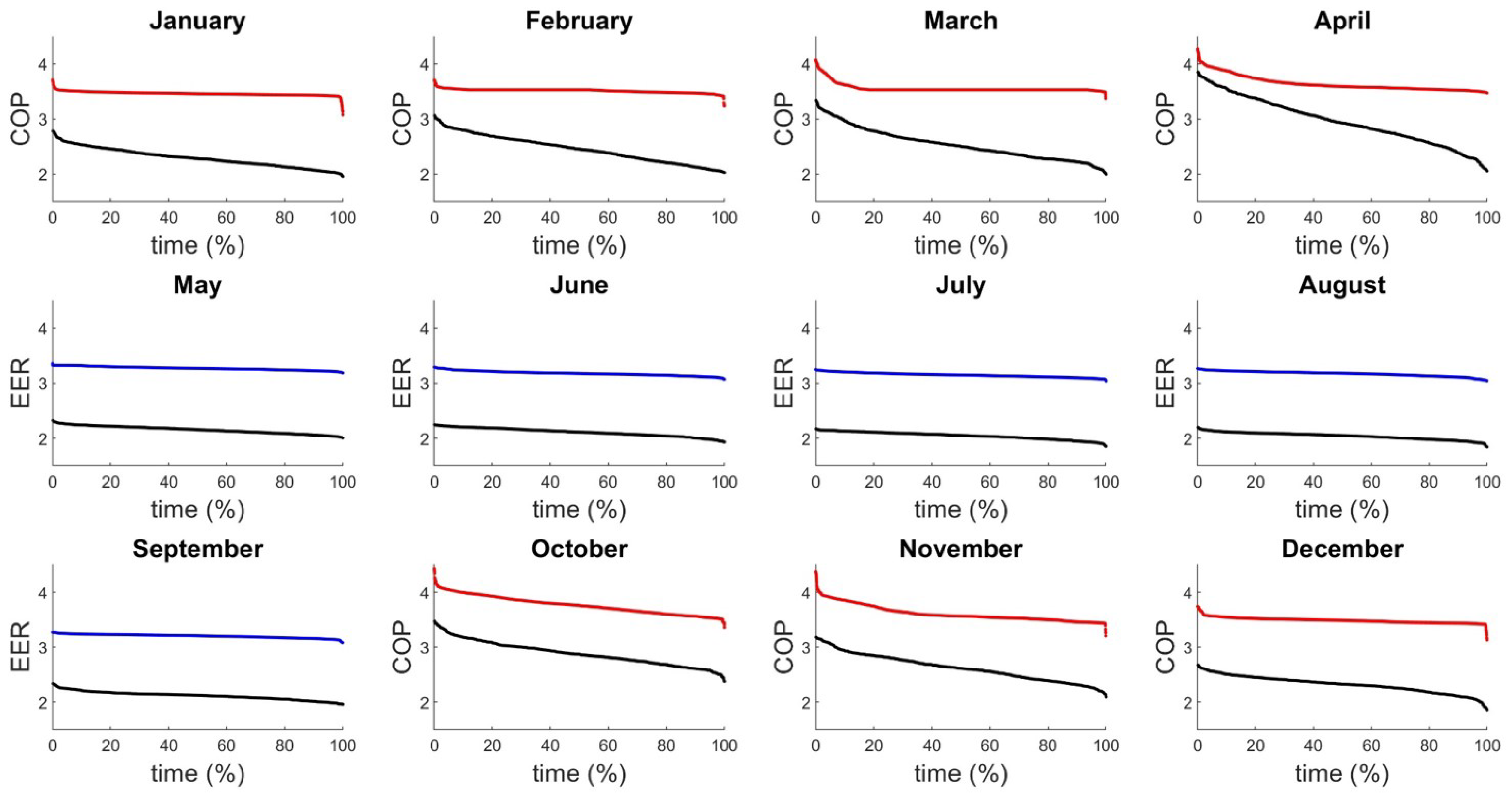
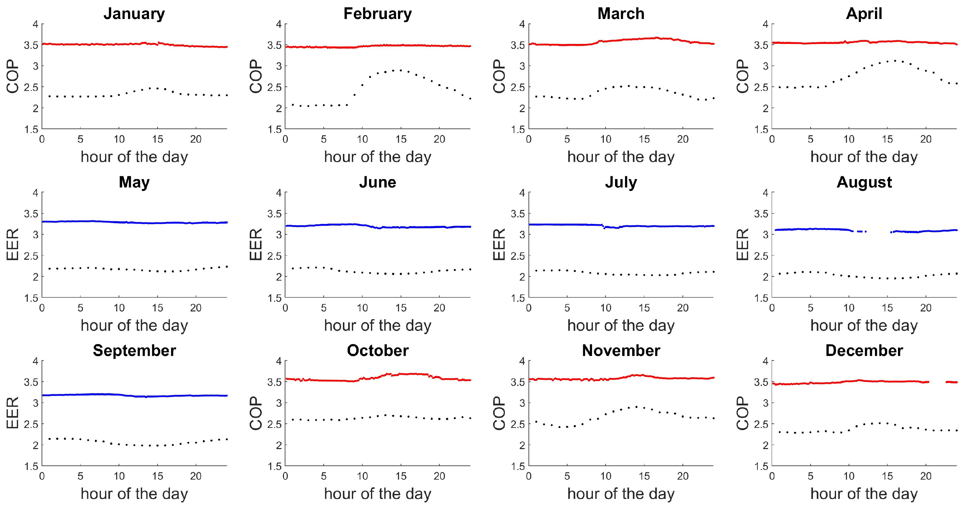
Once the refrigerant is fixed, it is also possible to predict the performance of the heat pump for different temperatures of the evaporative towers circuit without using preheating through the heat exchanger. The results of this study can be seen in Figure 10, where the COP is calculated for the months that have a heating demand from the temperature measurements of the evaporative towers circuit supply line and is indicated through red lines. While the EER, represented with blue lines, is calculated from the temperature measurements of the evaporative towers circuit return line for the months with cooling demand. The values are sorted in decreasing order to generate the heat pump performance duration curves. The black lines in the Figure 10 were added to allow comparison with the performance of an air-to-water heat pump, with R134a as the refrigerant, not connected to a 5GDHN but operating between the outdoor temperature and the temperature of the thermo-hydraulic circuit. In this way, it is possible to quantify the benefits of connecting to 5GDHN to recover waste heat and increase the efficiency of the heat pump compared to a stand-alone solution. A daily comparison between water-to-water heat pump and air-to-water heat pump is presented in Figure 11, where the performance for the characteristic day of different months, the 15th day of each month, is shown. From Figure 11 it can be seen how the water-to-water heat pump performance values (red and blue lines) are more stable during the day, while the air-to-water performance values (black dots) change over time and are lower. In quantitative terms, the increase in average performance for different months of the grid connected heat pump compared with the air-to-water heat pump is shown in Table 4, for the heating mode, and in Table 5, for the cooling mode.
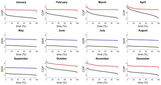
Figure 10.
Red and blue lines: COP and EER, respectively, for a water-to-water heat pump connected to the 5GDHN, using R134a as the refrigerant. Black lines: COP and EER for an air-to-water heat pump not connected to the 5GDHN, using R134a as the refrigerant.
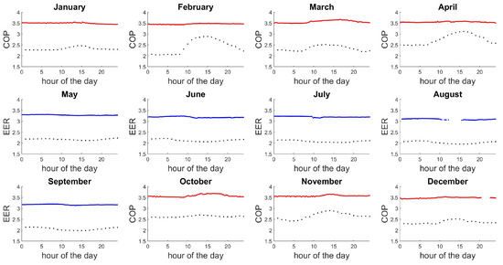
Figure 11.
Daily comparison between 5GDHN and stand alone solution, for each months is considered the 15th day. Red and blue lines: COP and EER, respectively, for a water-to-water heat pump connected to the 5GDHN, using R134a as the refrigerant. Black lines: COP and EER for an air-to-water heat pump, using R134a as the refrigerant.
Table 4.
Increased average performance of the grid connected heat pump compared with the air-to-water heat pump, in heating mode.
Table 5.
Increased average performance of the grid connected heat pump compared with the air-to-water heat pump, in cooling mode.
Connection with 5GDHN decouples heat pump operation from outdoor air temperature. In this way, there is not the disadvantage of an air-to-water heat pump for which an increase in outdoor air temperature also results in higher COP values but a decrease in building heat load. Another advantage of adopting a water-to-water heat pump is that there is no need to reverse the operation from heat pump to chiller to allow evaporator defrosting in winter. This operation involves a decrease in the performance of the heat pump.
3.3. Substation Design
In reality, the actual values of COP and EER may deviate from the values predicted by the method based on the thermodynamic cycle of the heat pump refrigerant. This is because some simplifying assumptions are made with this model. Therefore, to characterise the real performance of the heat pump and thus the behaviour of the entire 5GDHN substation, the installation of the prototype is fundamental. With the prototype, it will be possible to monitor the proper operation of the substation and the real performance. Therefore, careful design, defined by the implementation of the P&ID, is also necessary to enable the future construction of the prototype substation. In addition, it will be possible to take into account the seasonal value of COP by also considering the consumption of the decentralised pumping system.
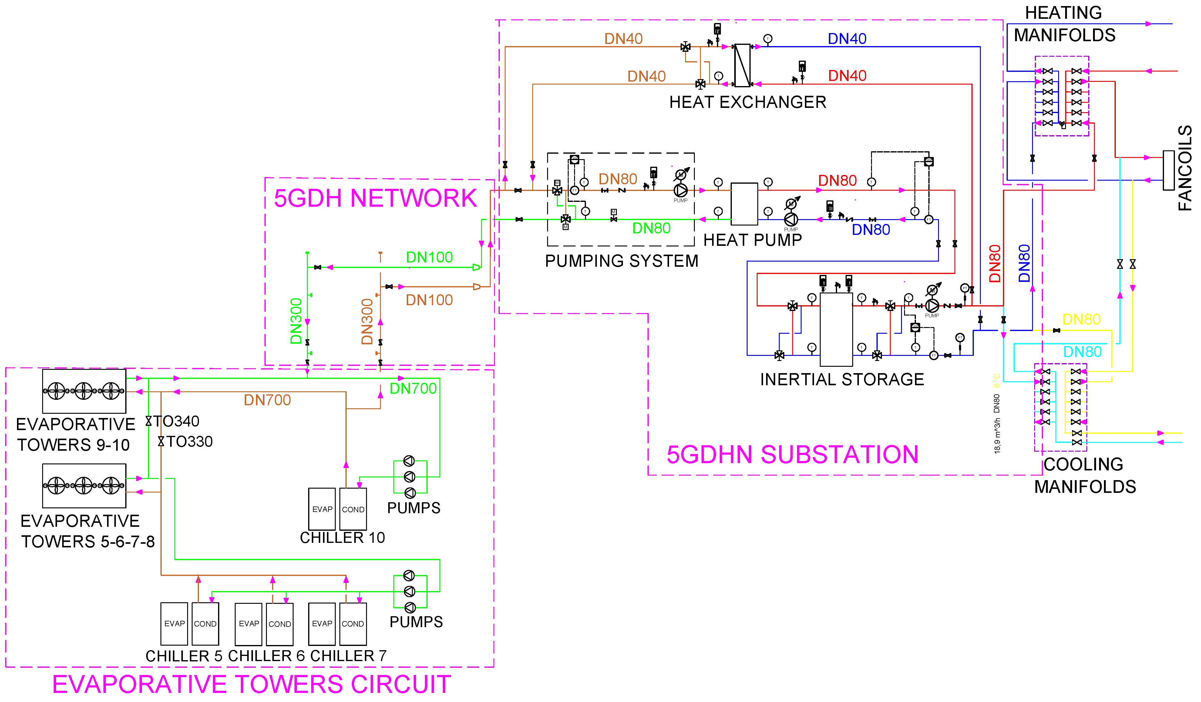
The first step of the prototype design is the realisation of the process flow diagram (PFD). The PFD includes the evaporative towers circuit, the 5GDHN, the substation, and the thermo-hydraulic circuit, consisting of the heating and cooling manifolds and fancoils. Figure 12 shows the PFD with the main components of the plant and piping size.
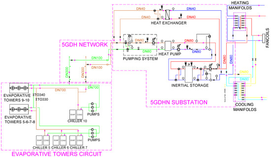
Figure 12.
Process flow diagram of 5GDHN and substation.
In the evaporative towers circuit, the heat produced by the centralised chillers feeding the district cooling network is dissipated. Specifically, chiller 10 employs evaporative towers 9 and 10 to dissipate heat, while chillers 5, 6, and 7 employ evaporative towers 5, 6, 7, and 8. Through the valves TO330 and TO340 evaporative towers 9 and 10 can be connected with the other evaporative towers. The orange lines represent the high temperature lines in the evaporative towers circuit, directed to the evaporative towers, while green lines represent the low-temperature lines, coming from the evaporative towers. The detour for the 5GDHN supply line is realised on the pipe at the condenser outlet of chiller 10, which consists of a 700 mm diameter (DN700) uninsulated carbon steel piping, the high-temperature fluid of the evaporative towers circuit flows in this piping. The return line of 5GDHN is connected to the DN700 uninsulated carbon steel piping at the outlet of evaporative towers 9 and 10, the fluid cooled by the evaporative towers flows into this piping.
The 5GDHN connects the evaporative towers circuit to the substation and consists of two DN300 uninsulated carbon steel piping. This pipeline starts from the two piping of the DN700 evaporative towers circuit and terminates with flanged ends. From the DN300 pipeline, two DN100 piping, also made of uninsulated carbon steel, go to the substation, reduced to DN80 before the bidirectional pumping system.
The main elements of the substation, located at the end of 5GDHN, are:
- The bidirectional pumping system.
- The heat pump.
Only for this prototype and not for a standard substation the following components are added:
- The heat exchanger, to test the performance of the heat pump over a wider temperature range.
- The inertial thermal energy storage, used to maximise heat pump performance by decoupling heating–cooling demand from the heat pump.
The first component of the substation prototype is the bidirectional pumping system, which connects the grid to the heat pump. An intermediate circuit is required between the heat pump and the inertial thermal energy storage, which is made of DN80 insulated carbon steel piping. A secondary circuit, also made of DN80 insulated carbon steel piping, then connects the inertial thermal energy storage to the heating and cooling manifolds. In addition, heat can also be transferred from the thermo-hydraulic circuit to the grid through the heat exchanger. On the 5GDHN side, two DN40 uninsulated carbon steel piping go to the heat exchanger, while, on the thermo-hydraulic circuit side, two DN40 insulated carbon steel piping go to the heat exchanger. The substation ends with the heating and cooling manifolds, where the piping leading to the fancoils begin. The heating and cooling manifolds and fancoils circuit are already installed and currently fed by traditional district heating.
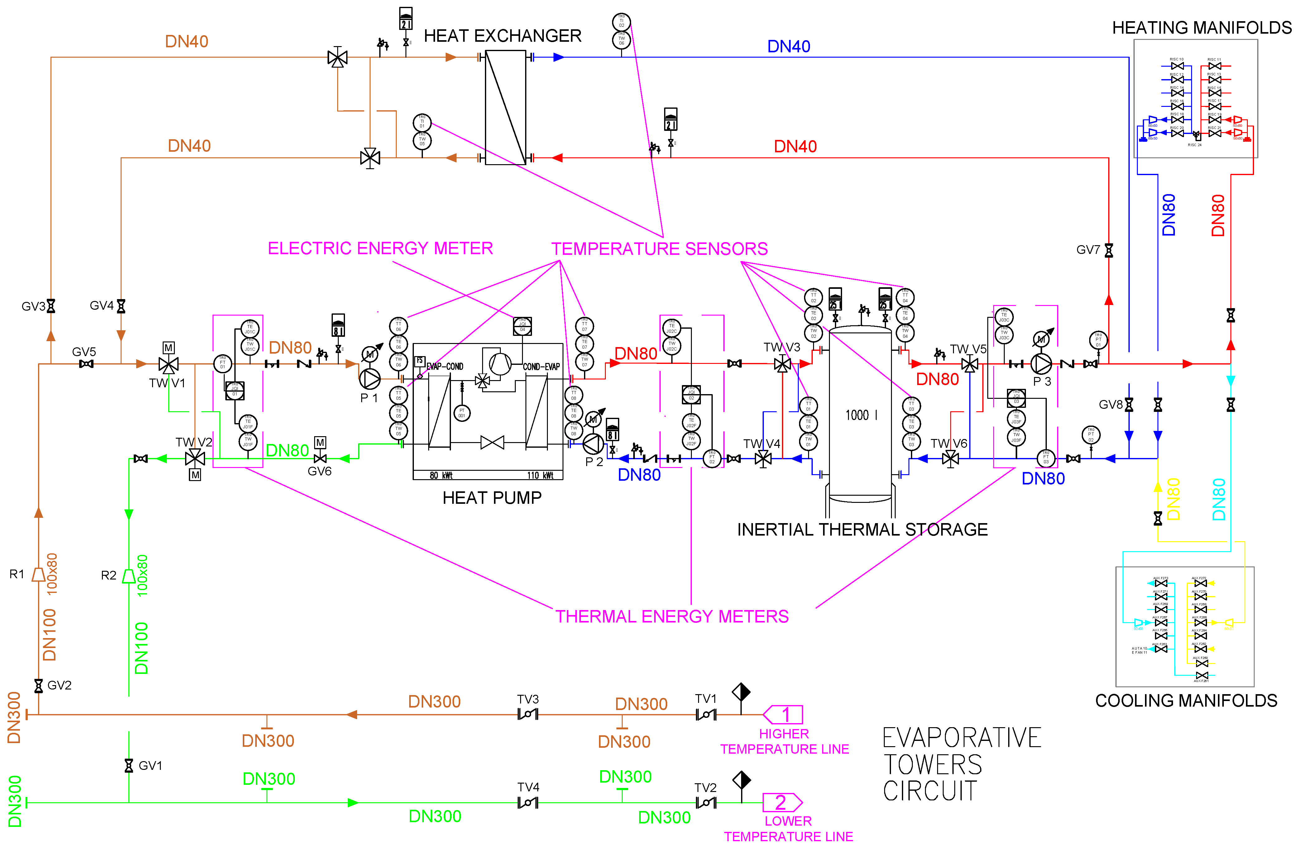
More accurate design is achieved with the P&ID. The P&ID, shown in Figure 13, presents all the components required for the proper operation of the 5GDHN substation. The detachment from the evaporative towers circuit is represented by the orange and green lines. Specifically, the orange line (detachment 1) represents the highest temperature 5GDHN line (supply line). On the other hand, the green line (detachment 2) indicates the lowest temperature 5GDHN line (return line). Valves TV1, TV2, TV3, TV4 are throttle valves of DN300, TV1 and TV2 are valves for detachment from the evaporative towers circuit. GV1 and GV2 valves are two globe valves of DN100, which are necessary for the diverting DN100 piping deviation from DN300 pipeline. Two reductions, R1 and R2, are placed to reduce the diameter of the pipeline from DN100 to DN80. Downstream of the 5GDHN is located the substation, which components are described in detail.
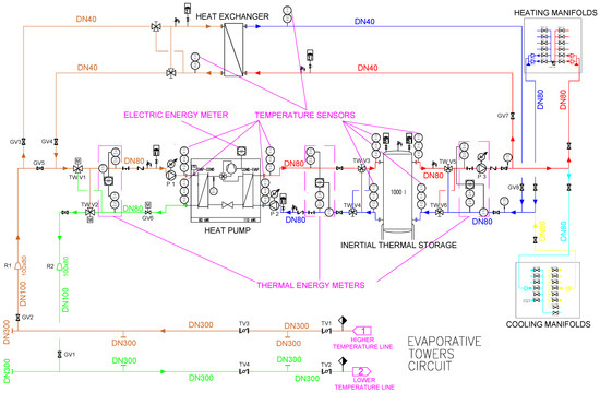
Figure 13.
Piping and instrumentation diagram of 5GDHN and substation.
- The connection between the grid and the heat pump is not direct, as shown in previous sections, but there is the bidirectional pumping system, consisting of a pair of three-way valves TWV1, TWV2, and the network pump P1. These DN80 three-way valves are motorised and maximise the performance of the 5GDHN in the dual heating and cooling configuration. Pump P1 is a variable speed pump, regulated by the pressure of the heat pump evaporator, in heating configuration, or by the pressure of the chiller condenser, in cooling mode. The GV6 valve is a motorised globe valve of DN80, required to enable the proper operation of the pump P1 under all pressure condition of the evaporative towers circuit.
- The water-to-water heat pump chosen for the substation prototype is a gas side reversible heat pump with R134a as the refrigerant. The heat pump employs two scroll compressors with two separate circuits to increase performance even at partial loads, the total heat output is 100 kW.
- To maximise heat pump performance, inertial thermal energy storage with a storage capacity of 1000 liters is required to decouple heating or cooling demand from the heat pump. Thus, there is an intermediate circuit to connect the heat pump to the inertial storage, where pump P2 operates only if the heat pump is on. The inlet and outlet of the storage tank are equipped with manual three-way valves (TWV3, TWV4, TWV5, TWV6) of DN80 to allow the storage tank to be used for both heating and cooling. In heating mode, the higher temperature fluid, reserved for supplying the thermo-hydraulic circuit, is stored in the upper side of the inertial storage. In contrast, in cooling mode, the fluid reserved for supplying the thermo-hydraulic circuit has a lower temperature than the return one, so it is stored in the lower part of the inertial storage. From the outlet of the inertial storage tank, the heat transfer fluid is pumped by pump P3 to the heating manifolds, in the heating configuration. While, in the cooling configuration, the heat transfer fluid is pumped to the cooling manifolds by the same pump P3. Pump P3 is a variable speed pump controlled by the pressure difference in the secondary circuit.
- Globe valves of DN40 GV3 and GV4 are used to connect the supply line of the grid with the heat exchanger, while GV5 is a DN80 globe valve. When valves GV3 and GV4 are open, while valve GV5 is still closed, the heat carrier fluid is heated before the evaporator heat pump inlet. Contrary, when GV3 and GV4 are still closed end GV5 is open, the supply line is directly connected to the heat pump. Valves GV7 and GV8 are globe valves of DN40 that allow the heat exchanger to be connected to the secondary circuit and transfer heat to the carrier fluid of the 5GDHN to heat it up to 40 °C, using heat from the thermo-hydraulic circuit.
To monitor heat pump performance and enable data acquisition, the substation prototype is equipped with several instruments measuring.
- A thermal energy meters is installed in the 5GDHN, which is necessary to store data on the heat exchanged with the heat pump. The thermal energy meter consist of two Pt100 temperature sensors (TE), one installed in the supply line and the other in the return line, an ultrasonic flow sensor (FT) and a meter device (JQI) connected to the temperature and flow sensors.
- In addition, thermal energy meters are placed in the intermediate circuit and secondary circuit, the former is needed to monitor the performance of the heat pump, and the latter to measure the heat demand of the building.
- The power consumed by the heat pump compressors will be measured by an electric energy meter (JQI04) located inside the heat pump.
- To monitor the real temperature of the heat transfer fluid in both the intermediate and secondary circuit, four Pt100 temperature sensors will be placed at the inlets and outlets of the thermal inertial storage: TT01, TT02, TT03, and TT04.
- Pt100 temperature sensors will also be installed at the inlets and outlets of the heat pump (TT05, TT06, TT07, and TT08) to monitor the performance of the heat pump as a function of the heat transfer fluid temperature of the 5GDHN. In this way, the COP of the heat pump can be monitored as a function of 5GDHN temperatures.
- Two pressure sensors, PT01 and PT02, will be installed to measure the pressure difference in the secondary circuit and used to regulate pump P3.
- To keep the operation of the heat exchanger under control, temperature sensors, TI01 and TI02, will be placed at the outlet of the heat exchanger, for both the 5GDHN and the thermo-hydraulic circuit.
All other components, such as valves, check valves, filters, and expansion vessels, are also visible in the P&ID.
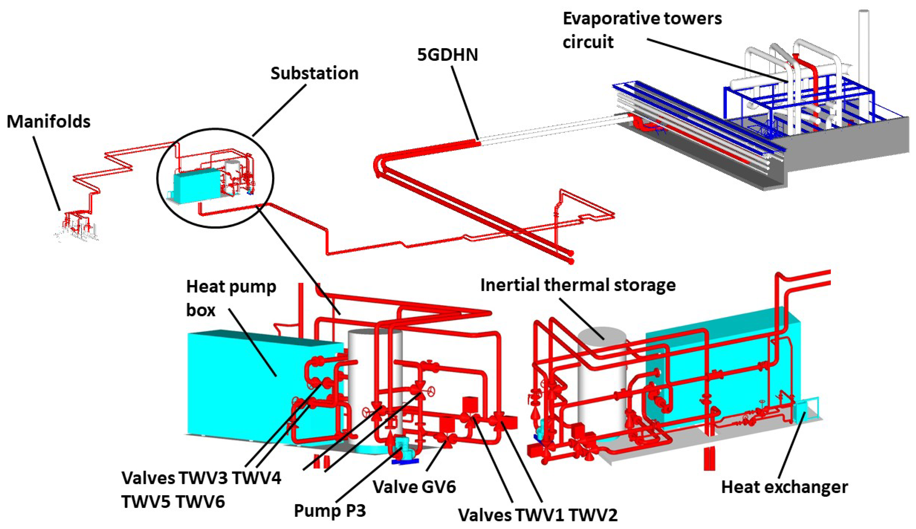
To complete the design phase, the three-dimensional design of the substation is reported in Figure 14. This figure shows the layout and encumbrance of 5GDHN, with the detachment from the evaporative towers circuit, substation, and thermo-hydraulic circuit with manifolds. The pair of three-way valves TWV1 and TWV2, the valve GV6 and pump P3 are represented in the substation enlargement, while the network pump P1 and intermediate circuit pump P2 are incorporated in the heat pump box. Additionally, visible are inertial thermal storage and three-way manual valves TWV3, TWV4, TWV5, and TWV6, which connect the thermal storage to the heat pump and thermo-hydraulic circuit.

Figure 14.
Three-dimensional design of the substation.
4. Conclusions
Among the actions to increase the sustainability and the use of renewable energies in the city of Brescia, A2A Calore & Servizi is planning to realise a 5th generation district heating network. In this paper, the design of a 5GDHN substation prototype is illustrated. The implementation of the prototype is required to verify the proper operation and test the performance of a 5th generation substation because of substantial difference with respect to the case of direct connection between the grid and buildings, as in traditional district heating networks. The prototype is powered by low-temperature waste heat produced in an energy hub, specifically centralised chillers are used to recreate a 5GDHN to which the prototype substation is connected. The substation enables the operation as a prosumer for a building with heating and cooling demand and consists of a bidirectional pumping system, a reversible water-to-water heat pump, a heat exchanger, and an inertial thermal storage. The layout of the bidirectional pumping system required to efficiently couple a reversible heat pump and a two-pipe 5GDHN is described in detail. In addition, for the heat pump, an analysis is conducted to determine the refrigerant that offers the best heat pump performance. A pumping system based on a couple of motorized three-way valves and a reversible water-to-water heat pump using R134a as the refrigerant has been selected for the prototype substation. R134a appear as the refrigerant with the best performance for the temperature range of the specific case study, but a high value of GWP characterises this refrigerant. An interesting alternative solution is the R1234ze, which, with similar performance but a lower GWP value, could replace R134a in the future. The difficulty of finding a 100 kW reversible heat pump on the market has influenced the choice of R134a as the refrigerant. In the future, in the first half of 2023 the substation prototype will be built at the A2A Calore & Servizi North Plant in Brescia, through the careful design described with the PFD and P&ID. To enable accurate analysis of the prototype substation through the acquired data, the prototype is equipped with sensors and instruments, as shown in the P&ID. With all these data, it will be possible to determine the COP and EER of the heat pump and the seasonal COP and EER, which include the energy absorbed by the pumping system. In this way, the validation of the numerical estimations for the definition of the COP and EER and the verification of the proper operation of the bidirectional pumping system will be carried out.
Author Contributions
Conceptualization, G.M. and D.P.; software, G.M.; writing—original draft preparation, G.M.; writing—review and editing, A.M.L., G.M. and M.P.; supervision, A.M.L., D.P. and M.P.; project administration, D.P.; funding acquisition, A.M.L. and M.P. All authors have read and agreed to the published version of the manuscript.
Funding
This research was funded by MUR, fund PON “Ricerca e Innovazione” 2014–2020, Azione IV.4 “Dottorati e contratti di ricerca su tematiche dell’innovazione” and Azione IV.5 “Dottorati su tematiche green”.
Institutional Review Board Statement
Not applicable.
Informed Consent Statement
Not applicable.
Data Availability Statement
The data used are confidential.
Acknowledgments
The authors thank the other people who are working on the development of the 5GDHN and the substation prototype. In particular: Paola Alessandrini, Andrea Coppedè, Silvia Tosato and Gabriele Vespa.
Conflicts of Interest
The authors declare no conflict of interest.
Abbreviations
The following abbreviations are used in this manuscript:
| 1GDHN | 1st Generation District Heating Network |
| 2GDHN | 2nd Generation District Heating Network |
| 3GDHN | 3rd Generation District Heating Network |
| 4GDHN | 4th Generation District Heating Network |
| 5GDHN | 5th Generation District Heating Network |
| CHP | Combined heat and power |
| COP | Coefficient of performance |
| EER | Energy efficiency ratio |
| GWP | Global warming potential |
| PFD | Process flow diagram |
| P&ID | Piping and instrumentation diagram |
| DNXX | XX mm diameter piping |
References
- Commission, E. Communication from the Commission to the European Parliament, the Council, the European Economic and Social Committee and the Committee of the Regions an EU Strategy on Heating and Cooling. 2016. Available online: https://energy.ec.europa.eu/topics/energy-efficiency/heating-and-cooling_en (accessed on 20 July 2022).
- A European Green Deal. Available online: https://ec.europa.eu/info/strategy/priorities-2019-2024/european-green-deal_en (accessed on 20 July 2022).
- Lund, H.; Moller, B.; Mathiesen, B.; Dyrelund, A. The role of district heating in future renewable energy systems. Energy 2010, 35, 1381–1390. [Google Scholar] [CrossRef]
- Lund, H.; Werner, S.; Wiltshire, R.; Svendsen, S.; Thorsen, J.E.; Hvelplund, F.; Mathiesen, B.V. 4th Generation District Heating (4GDH). Integrating smart thermal grids into future sustainable energy systems. Energy 2014, 68, 1–11. [Google Scholar] [CrossRef]
- Reiners, T.; Gross, M.; Altieri, L.; Wagner, H.J.; Bertsch, V. Heat pump efficiency in fifth generation ultra-low temperature district heating networks using a wastewater heat source. Energy 2021, 236, 121318. [Google Scholar] [CrossRef]
- Quirosa, G.; Torres, M.; Chacartegui, R. Analysis of the integration of photovoltaic excess into a 5th generation district heating and cooling system for network energy storage. Energy 2022, 239, 122202. [Google Scholar] [CrossRef]
- Hermansen, R.; Smith, K.; Thorsen, J.E.; Wang, J.; Zong, Y. Model predictive control for a heat booster substation in ultra low temperature district heating systems. Energy 2022, 238, 121631. [Google Scholar] [CrossRef]
- Buffa, S.; Cozzini, M.; D’Antoni, M.; Baratieri, M.; Fedrizzi, R. 5th generation district heating and cooling systems: A review of existing cases in Europe. Renew. Sustain. Energy Rev. 2019, 104, 504–522. [Google Scholar] [CrossRef]
- Calixto, S.; Cozzini, M.; Manzolini, G. Modelling of an existing neutral temperature district heating network: Detailed and approximate approaches. Energies 2021, 14, 379. [Google Scholar] [CrossRef]
- García-Céspedes, J.; Herms, I.; Arnó, G.; de Felipe, J.J. Fifth-Generation District Heating and Cooling Networks Based on Shallow Geothermal Energy: A review and Possible Solutions for Mediterranean Europe. Energies 2023, 16, 147. [Google Scholar] [CrossRef]
- Meibodi, S.S.; Loveridge, F. The future role of energy geostructures in fifth generation district heating and cooling networks. Energy 2022, 240, 122481. [Google Scholar] [CrossRef]
- Directive (EU) 2018/2002 of the European Parliament and of the Council of 11 December 2018 Amending Directive 2012/27/EU on Energy Efficiency. Available online: https://eur-lex.europa.eu/legal-content/EN/TXT/?uri=uriserv:OJ.L_.2018.328.01.0210.01.ENG (accessed on 21 January 2023).
- Pattijn, I.P.; Baumans, A. Fifth-generation thermal grids and heat pumps: A pilot project in Leuven, Belgium. HPT Mag. 2017, 35, 53–57. [Google Scholar]
- Verhoeven, R.; Willems, E.; Harcouët-Menou, V.; Boever, E.D.; Hiddes, L.; Op’t Veld, P.; Demollin, E. Minewater 2.0 project in Heerlen The Netherlands: Transformation of a geothermal mine water pilot project into a full scale hybrid sustainable energy infrastructure for heating and cooling. Energy Procedia 2014, 46, 58–67. [Google Scholar] [CrossRef]
- Joint Research Centre and Institute for Environment and Sustainability; Mutka, K.; Papillon, P.; Kalf, R.; Stryi-Hipp, G.; Weiss, W.; Sanner, B.; Land, A. 2020–2030–2050, Common Vision for the Renewable Heating and Cooling Sector in Europe: European Technology Platform on Renewable Heating and Cooling; Publications Office of the European Union: Luxembourg, 2011. [Google Scholar] [CrossRef]
- Pipiciello, M.; Caldera, M.; Cozzini, M.; Ancona, M.A.; Melino, F.; Pietra, B.D. Experimental characterization of a prototype of bidirectional substation for district heating with thermal prosumers. Energy 2021, 223, 120036. [Google Scholar] [CrossRef]
- Wirtz, M.; Kivilip, L.; Remmen, P.; Müller, D. 5th Generation District Heating: A novel design approach based on mathematical optimization. Appl. Energy 2020, 260, 114158. [Google Scholar] [CrossRef]
- Gudmundsson, O.; Schmidt, R.R.; Dyrelund, A.; Thorsen, J.E. Economic comparison of 4GDH and 5GDH systems–Using a case study. Energy 2022, 238, 121613. [Google Scholar] [CrossRef]
- Zeh, R.; Ohlsen, B.; Philipp, D.; Bertermann, D.; Kotz, T.; Jocic, N.; Stockinger, V. Large-scale geothermal collector systems for 5th generation district heating and cooling networks. Sustainability 2021, 13, 6035. [Google Scholar] [CrossRef]
- A2A Calore & Servizi. Available online: https://www.a2acaloreservizi.eu/teleriscaldamento/impianti-e-reti/area-brescia (accessed on 20 July 2022).
- TEMPO. Available online: https://cordis.europa.eu/project/id/768936 (accessed on 20 July 2022).
- Pilotelli, M.; Grassi, B.; Lezzi, A.M.; Beretta, G.P. Flow models of perforated manifolds and plates for the design of a large thermal storage tank for district heating with minimal maldistribution and thermocline growth. Appl. Energy 2022, 322, 119436. [Google Scholar] [CrossRef]
- Pilotelli, M.; Grassi, B.; Pasinelli, D.; Lezzi, A.M. Performance analysis of a large TES system connected to a district heating network in Northern Italy. Energy Rep. 2022, 8, 1092–1106. [Google Scholar] [CrossRef]
- Smart-Grid-Pilot. Available online: https://www.a2acaloreservizi.eu/teleriscaldamento/progetti/smart-grid-pilot (accessed on 20 July 2022).
- Grassi, B.; Piana, E.A.; Beretta, G.P.; Pilotelli, M. Dynamic Approach to Evaluate the Effect of Reducing District Heating Temperature on Indoor Thermal Comfort. Energies 2021, 14, 25. [Google Scholar] [CrossRef]
- PVGIS. Available online: https://re.jrc.ec.europa.eu/pvg_tools/en/ (accessed on 20 July 2022).
- Licklederer, T.; Hamacher, T.; Kramer, M.; Peric, V.S. Thermohydraulic model of Smart Thermal Grids with bidirectional power flow between prosumers. Energy 2021, 230, 120825. [Google Scholar] [CrossRef]
- De Pascalis, L.; Starace, G. Un nuovo metodo di scelta dei compressori scroll a velocità variabile. Tekneco 2011, 4, 76–80. Available online: https://www.researchgate.net/publication/304897331 (accessed on 20 July 2022).

Disclaimer/Publisher’s Note: The statements, opinions and data contained in all publications are solely those of the individual author(s) and contributor(s) and not of MDPI and/or the editor(s). MDPI and/or the editor(s) disclaim responsibility for any injury to people or property resulting from any ideas, methods, instructions or products referred to in the content. |
© 2023 by the authors. Licensee MDPI, Basel, Switzerland. This article is an open access article distributed under the terms and conditions of the Creative Commons Attribution (CC BY) license (https://creativecommons.org/licenses/by/4.0/).