
Applicability Evaluation of Energy Slabs Installed in an Underground Parking Lot


Abstract
:1. Introduction
2. Construction of Energy Slabs in Underground Parking Lot
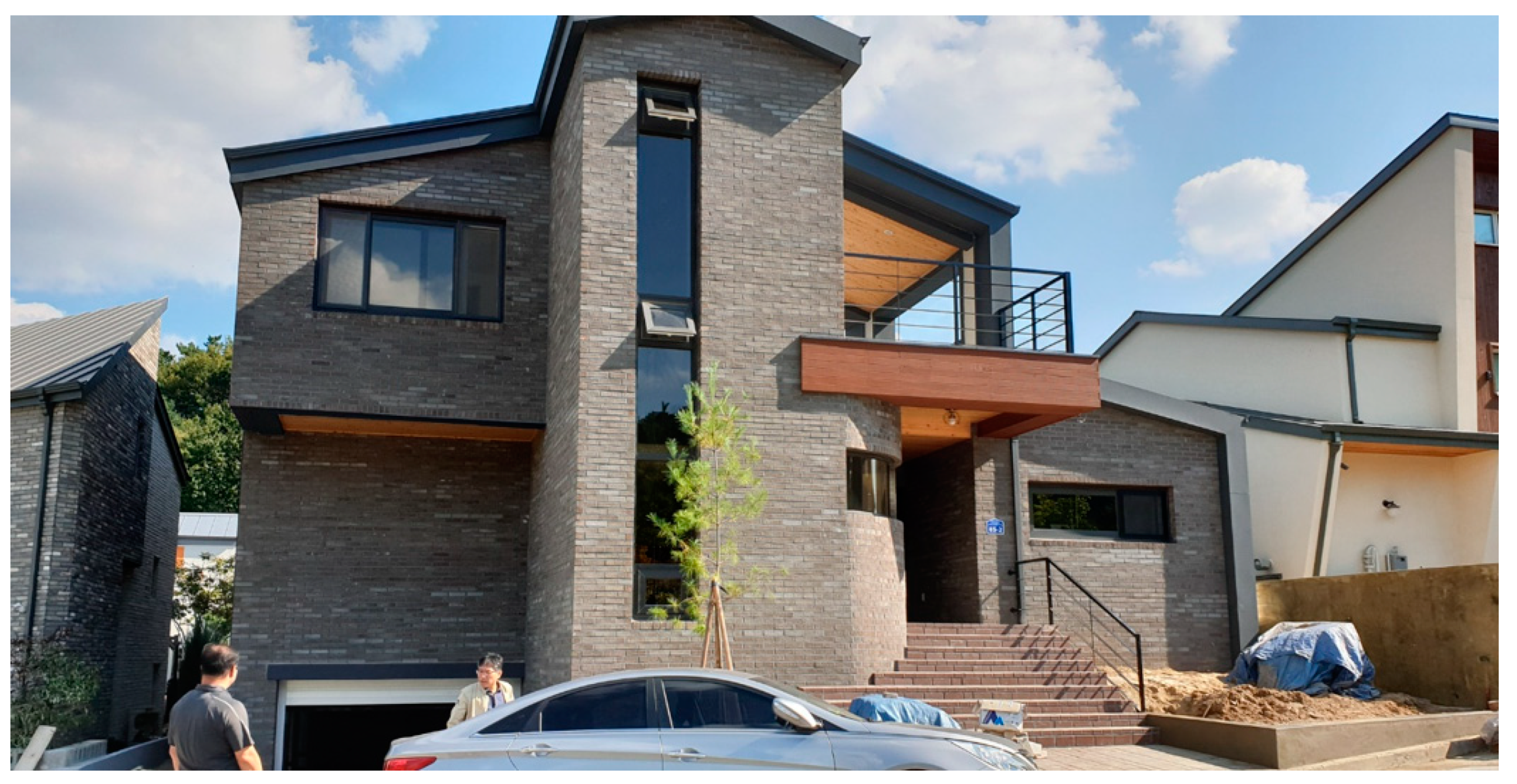
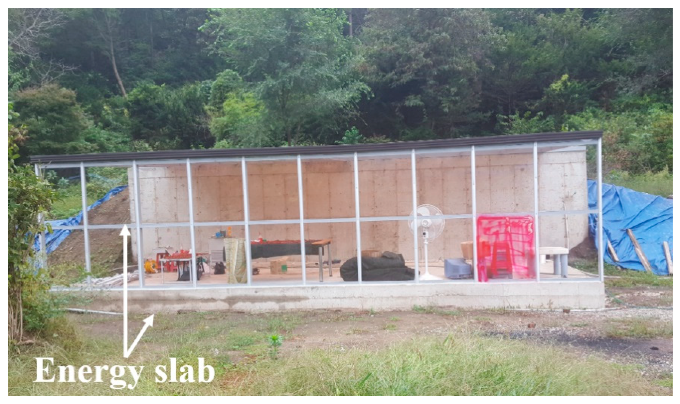
2.1. Overview of Construction Site
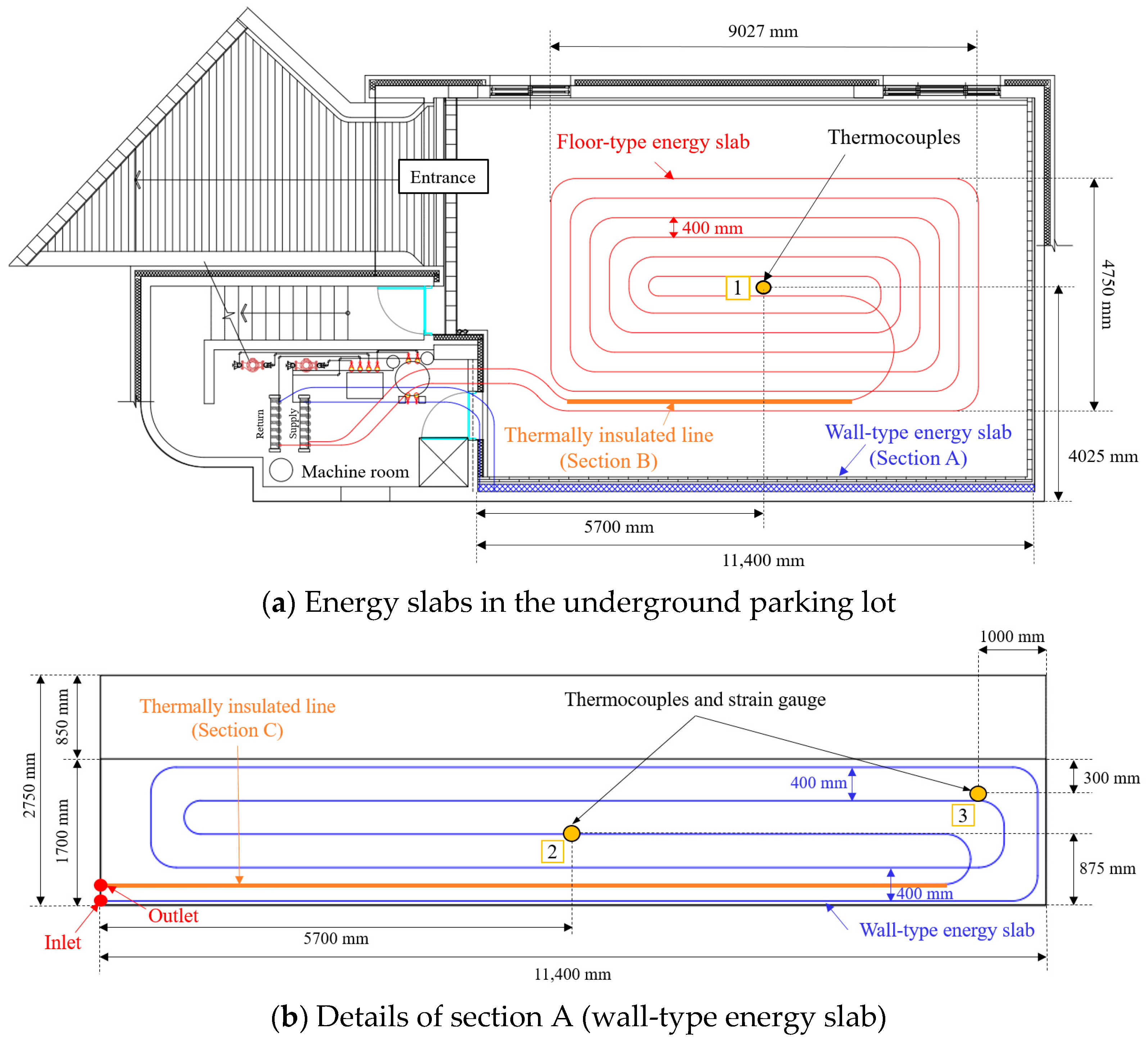
2.2. Design of Energy Slab in Underground Parking Lot
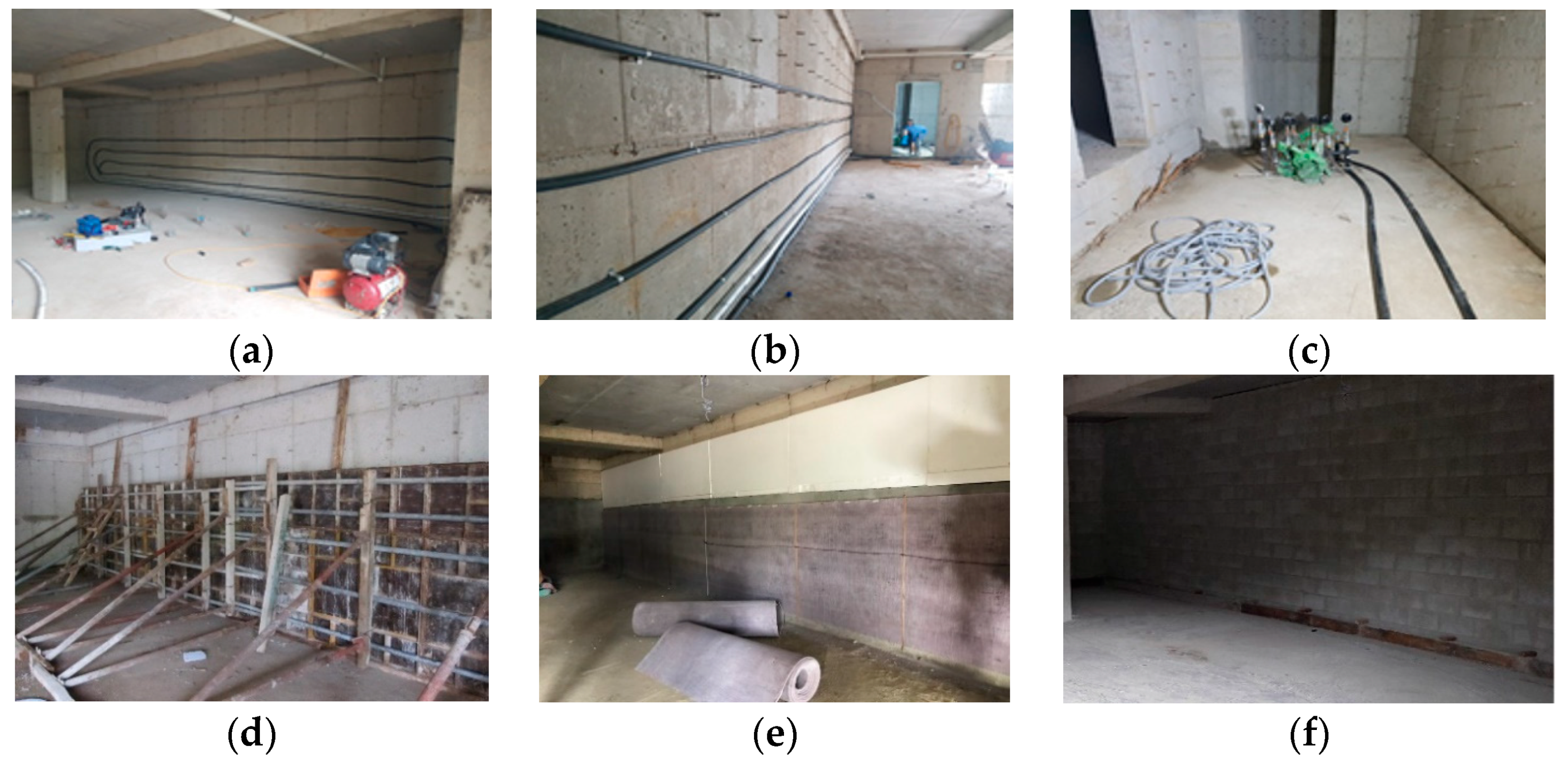
2.3. Construction Procedure of Energy Slabs
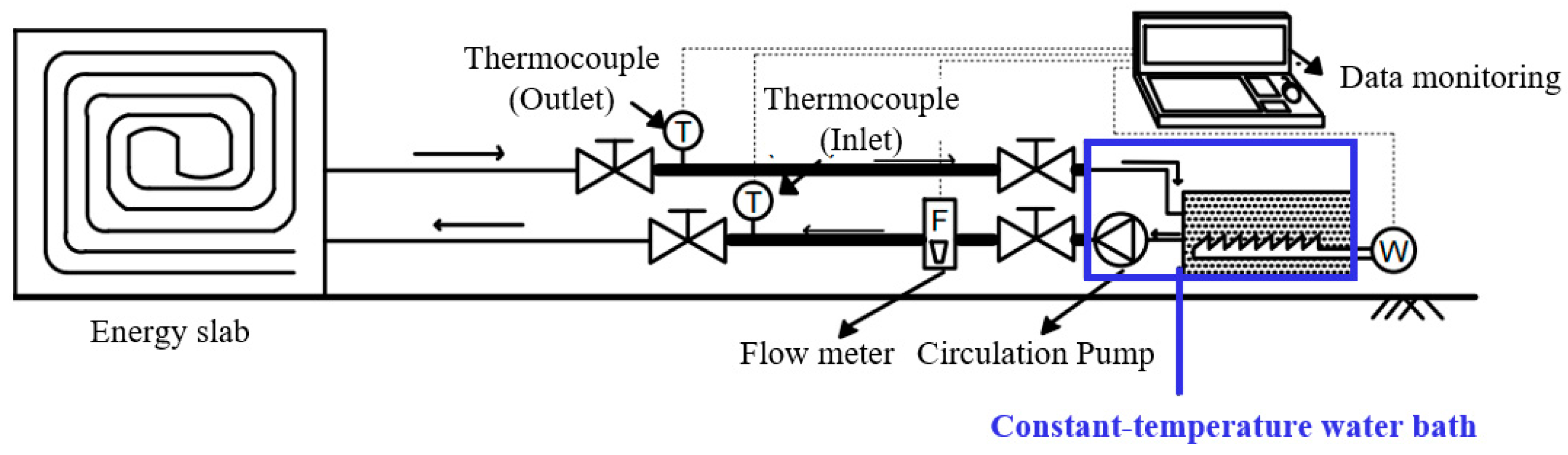
3. In Situ Thermal Performance Test (TPTs) with Constructed Energy Slabs
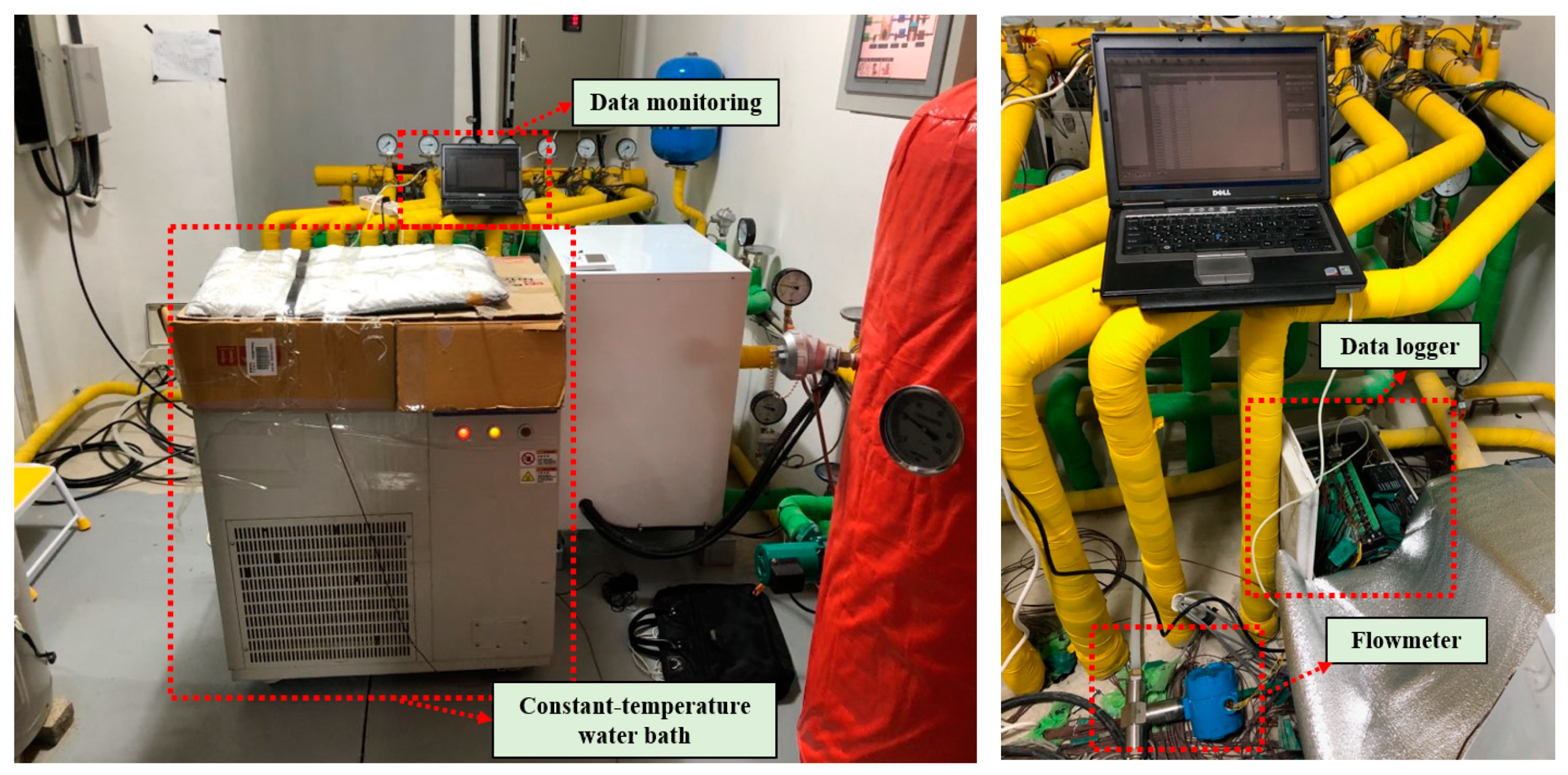
3.1. Experimental Conditions for In Situ TPT
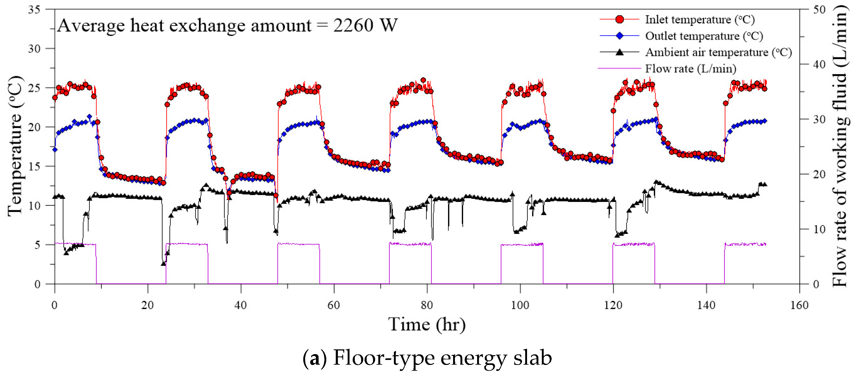
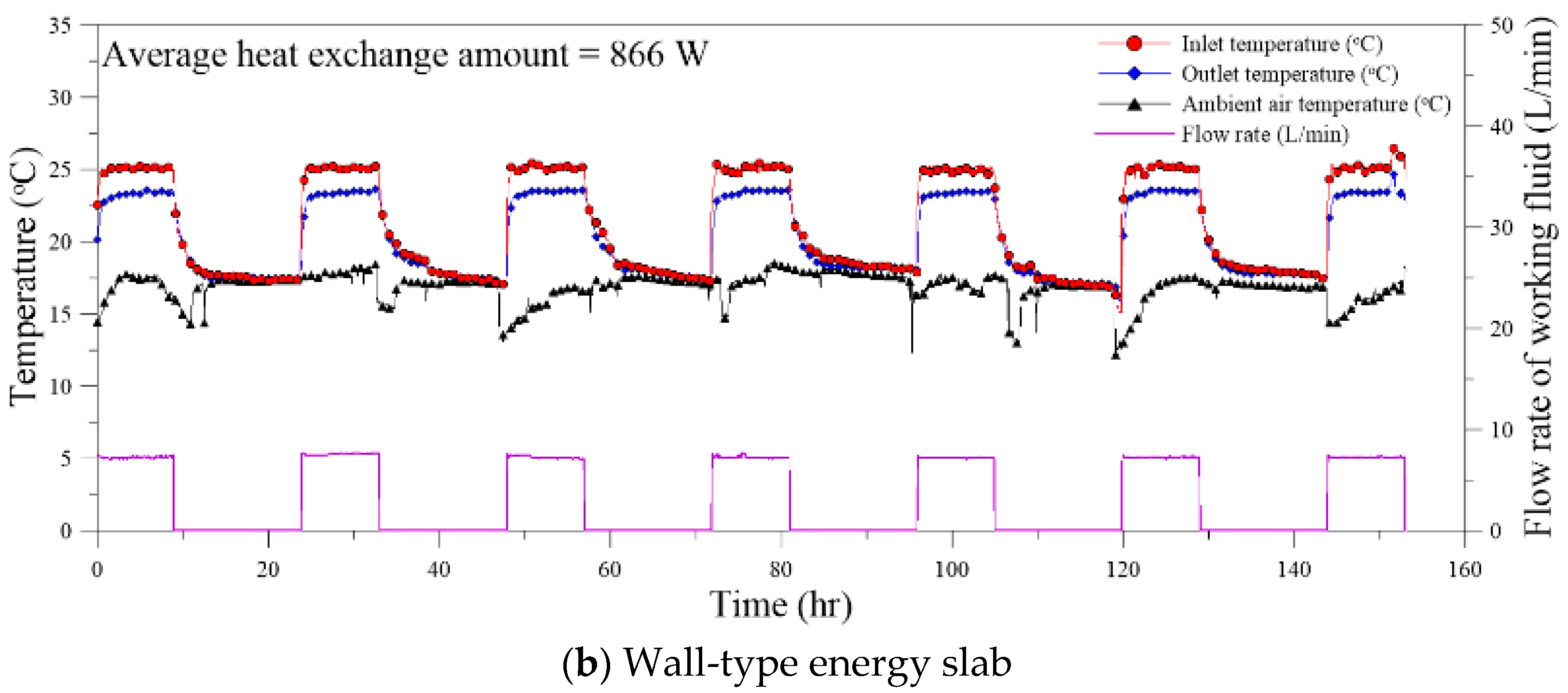
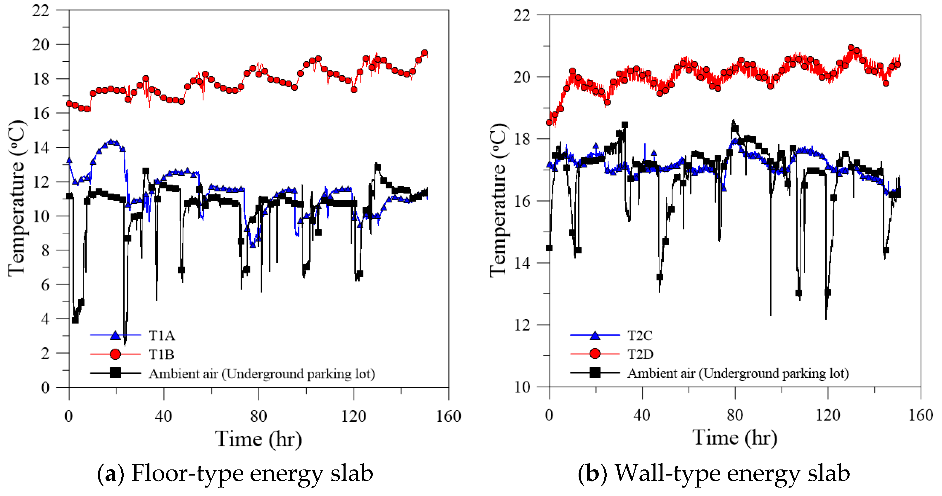
3.2. Result of TPTs
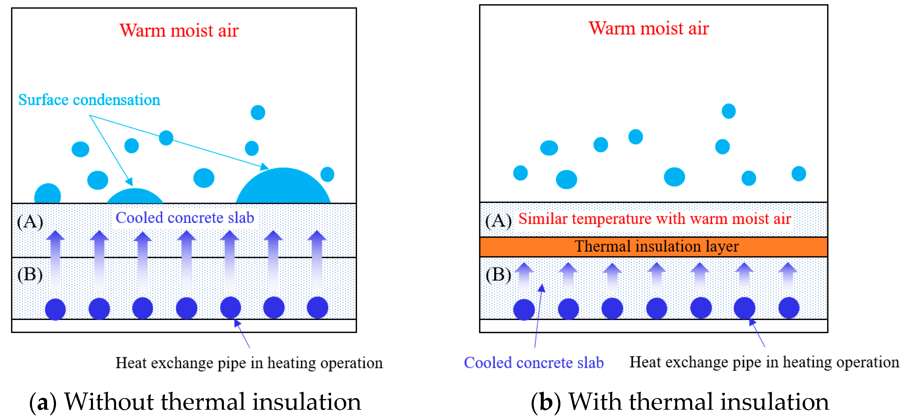
3.3. Investigation of Surface Condensation
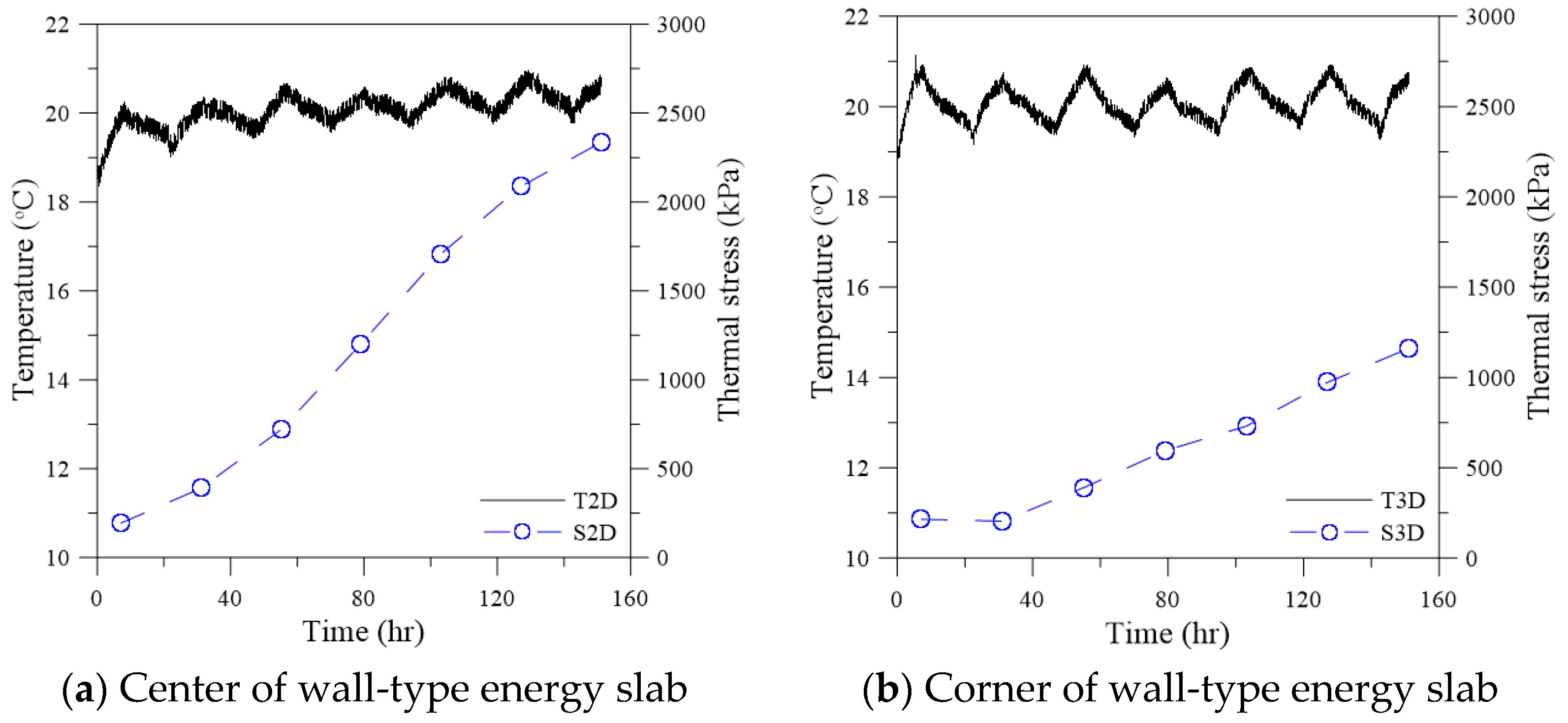
4. Structural Stability of Energy Slab in Underground Parking Lot
5. Conclusions
- The floor- and wall-type energy slabs equipped with aerogel-type thermal insulation showed a stable thermal performance in the underground parking lot. In particular, the energy slabs in this study increased the average heat exchange amount per unit area by 265% in comparison with the previous study, by reducing the thermal interference induced by the ambient air temperature.
- The aerogel-type thermal insulation layer thermally isolated the concrete slabs with the heat exchange pipes from the ambient air refrained from surface condensation. This is especially critical when the temperature in the concrete slab encasing the heat exchange pipes becomes lower than the ambient air temperature during the heating operation of the GSHP system.
- The maximum thermal stress was estimated to be approximately 2350 kPa at the end of the TPT. Therefore, it is necessary to secure enough tensile strength of the cement mortar for the energy slab, specially to manage the thermal stress induced by the cooling operation.
- The present study’s limitations are that the structural stability of the energy slab installed in the underground parking lot was investigated only in the cooling operation of the thermal performance tests (TPTs), and the tests were performed for seven days in accordance with the previous study. In future works, to overcome such limitations, the TPT in the heating operation should be performed to comprehensively quantify the effect of thermal stress on the structural stability of the energy slab. Furthermore, the maximum thermal stress is also necessary to be checked by performing a long-term TPT.
Author Contributions
Funding
Institutional Review Board Statement
Informed Consent Statement
Data Availability Statement
Conflicts of Interest
References
- Conti, J.; Holtberg, P.; Diefenderfer, J.; LaRose, A.; Turnure, J.T.; Westfall, L. International Energy Outlook 2016 with Projections to 2040; USDOE Energy Information Administration (EIA): Washington, DC, USA, 2016. [Google Scholar]
- Liu, R.; Salem, M.; Rungamornrat, J.; Al-Bahrani, M. A Comprehensive and Updated Review on the Exergy Analysis of Ground Source Heat Pumps. Sustain. Energy Technol. Assess. 2023, 55, 102906. [Google Scholar] [CrossRef]
- Huang, B.; Mauerhofer, V. Life Cycle Sustainability Assessment of Ground Source Heat Pump in Shanghai, China. J. Clean. Prod. 2016, 119, 207–214. [Google Scholar] [CrossRef]
- Hepbasli, A.; Akdemir, O. Energy and Exergy Analysis of a Ground Source (Geothermal) Heat Pump System. Energy Convers. Manag. 2004, 45, 737–753. [Google Scholar] [CrossRef]
- Kumar, S.; Murugesan, K. Optimization of Geothermal Interaction of a Double U-Tube Borehole Heat Exchanger for Space Heating and Cooling Applications Using Taguchi Method and Utility Concept. Geothermics 2020, 83, 101723. [Google Scholar] [CrossRef]
- Blum, P.; Campillo, G.; Kölbel, T. Techno-Economic and Spatial Analysis of Vertical Ground Source Heat Pump Systems in Germany. Energy 2011, 36, 3002–3011. [Google Scholar] [CrossRef]
- Esen, H.; Inalli, M.; Esen, M.; Pihtili, K. Energy and Exergy Analysis of a Ground-Coupled Heat Pump System with Two Horizontal Ground Heat Exchangers. Build. Environ. 2007, 42, 3606–3615. [Google Scholar] [CrossRef]
- Tarnawski, V.R.; Leong, W.H.; Momose, T.; Hamada, Y. Analysis of Ground Source Heat Pumps with Horizontal Ground Heat Exchangers for Northern Japan. Renew. Energy 2009, 34, 127–134. [Google Scholar] [CrossRef]
- Dinh, B.H.; Kim, Y.-S.; Yoon, S. Experimental and Numerical Studies on the Performance of Horizontal U-Type and Spiral-Coil-Type Ground Heat Exchangers Considering Economic Aspects. Renew. Energy 2022, 186, 505–516. [Google Scholar] [CrossRef]
- Xia, C.; Sun, M.; Zhang, G.; Xiao, S.; Zou, Y. Experimental Study on Geothermal Heat Exchangers Buried in Diaphragm Walls. Energy Build. 2012, 52, 50–55. [Google Scholar] [CrossRef]
- Peterson, E.L.; Shafagh, I. Evaluation of Diaphragm Wall Heat Exchanger Potential. Energy Build. 2022, 266, 112107. [Google Scholar] [CrossRef]
- Sterpi, D.; Tomaselli, G.; Angelotti, A. Energy Performance of Ground Heat Exchangers Embedded in Diaphragm Walls: Field Observations and Optimization by Numerical Modelling. Renew. Energy 2020, 147, 2748–2760. [Google Scholar] [CrossRef]
- Barla, M.; di Donna, A.; Santi, A. Energy and Mechanical Aspects on the Thermal Activation of Diaphragm Walls for Heating and Cooling. Renew. Energy 2020, 147, 2654–2663. [Google Scholar] [CrossRef]
- Bidarmaghz, A.; Narsilio, G.A. Heat Exchange Mechanisms in Energy Tunnel Systems. Geomech. Energy Environ. 2018, 16, 83–95. [Google Scholar] [CrossRef]
- Lee, C.; Park, S.; Choi, H.-J.; Lee, I.-M.; Choi, H. Development of Energy Textile to Use Geothermal Energy in Tunnels. Tunn. Undergr. Space Technol. 2016, 59, 105–113. [Google Scholar] [CrossRef]
- Barla, M.; di Donna, A.; Insana, A. A Novel Real-Scale Experimental Prototype of Energy Tunnel. Tunn. Undergr. Space Technol. 2019, 87, 1–14. [Google Scholar] [CrossRef]
- Insana, A.; Barla, M. Experimental and Numerical Investigations on the Energy Performance of a Thermo-Active Tunnel. Renew. Energy 2020, 152, 781–792. [Google Scholar] [CrossRef]
- Ma, C.; di Donna, A.; Dias, D. Numerical Study on the Thermo-Hydro-Mechanical Behaviour of an Energy Tunnel in a Coarse Soil. Comput. Geotech. 2022, 151, 105003. [Google Scholar] [CrossRef]
- Kayaci, N.; Demir, H.; Kanbur, B.B.; Atayilmaz, Ş.O.; Agra, O.; Acet, R.C.; Gemici, Z. Experimental and Numerical Investigation of Ground Heat Exchangers in the Building Foundation. Energy Convers. Manag. 2019, 188, 162–176. [Google Scholar] [CrossRef]
- Nam, Y.; Chae, H.-B. Numerical Simulation for the Optimum Design of Ground Source Heat Pump System Using Building Foundation as Horizontal Heat Exchanger. Energy 2014, 73, 933–942. [Google Scholar] [CrossRef]
- Choi, J.-M.; Sohn, B.-H. Performance Analysis of Energy-Slab Ground-Coupled Heat Exchanger. Korean J. Air-Cond. Refrig. Eng. 2012, 24, 487–496. [Google Scholar]
- Moon, C.-E.; Choi, J.M. Heating Performance Characteristics of the Ground Source Heat Pump System with Energy-Piles and Energy-Slabs. Energy 2015, 81, 27–32. [Google Scholar] [CrossRef]
- Lee, S.; Park, S.; Kang, M.; Choi, H. Field Experiments to Evaluate Thermal Performance of Energy Slabs with Different Installation Conditions. Appl. Sci. 2018, 8, 2214. [Google Scholar] [CrossRef]
- Lee, S.; Park, S.; Won, J.; Choi, H. Influential Factors on Thermal Performance of Energy Slabs Equipped with an Insulation Layer. Renew. Energy 2021, 174, 823–834. [Google Scholar] [CrossRef]
- Adinolfi, M.; Loria, A.F.R.; Laloui, L.; Aversa, S. Experimental and Numerical Investigation of the Thermo-Mechanical Behaviour of an Energy Sheet Pile Wall. Geomech. Energy Environ. 2021, 25, 100208. [Google Scholar] [CrossRef]
- Sterpi, D.; Coletto, A.; Mauri, L. Investigation on the Behaviour of a Thermo-Active Diaphragm Wall by Thermo-Mechanical Analyses. Geomech. Energy Environ. 2017, 9, 1–20. [Google Scholar] [CrossRef]
- Miyara, A.; Tsubaki, K.; Inoue, S.; Yoshida, K. Experimental Study of Several Types of Ground Heat Exchanger Using a Steel Pile Foundation. Renew. Energy 2011, 36, 764–771. [Google Scholar]
- Yurtdas, I.; Burlion, N.; Skoczylas, F. Experimental Characterisation of the Drying Effect on Uniaxial Mechanical Behaviour of Mortar. Mater. Struct. 2004, 37, 170–176. [Google Scholar] [CrossRef]
- Chen, X.; Wu, S.; Zhou, J. Influence of Porosity on Compressive and Tensile Strength of Cement Mortar. Constr. Build. Mater. 2013, 40, 869–874. [Google Scholar] [CrossRef]
- Singh, S.B.; Munjal, P.; Thammishetti, N. Role of Water/Cement Ratio on Strength Development of Cement Mortar. J. Build. Eng. 2015, 4, 94–100. [Google Scholar] [CrossRef]


| Type | Details |
|---|---|
| Location | Daejeon City, Korea |
| Purpose/Structure | Detached house/reinforced concrete |
| Land/Construction area | 410 m2/193 m2 |
| Total floor area | 386 m2 |
| Building scale | One basement floor (parking lot and machine room), two ground floors |
| Height | 9 m |
| Depth (m) | Division | Type | N-Value (Count/cm) |
|---|---|---|---|
| 0.0~2.7 | Buried layer | Silty sand with gravel | 4/30~13/30 |
| 2.7~3.7 | Sedimentary layer | Silty sand | 5/30 |
| 3.7~11.0 | Weathered soil | Silty sand | 17/30~50/13 |
| 11.0~15.3 | Weathered rock | Silty sand | 50/7~50/10 |
| Type of Energy Slab | Pipe Material | Pipe Diameter (mm) | Pitch (mm) | Installation Area (m2) | Total Length (m) |
|---|---|---|---|---|---|
| Floor type | High-density polyethylene (HDPE) | 25 | 400 | 49.5 | 123 |
| Wall type | 18.5 | 55 |
| Type of Energy Slab | Locations | Sensor Type | Name | |
|---|---|---|---|---|
| Floor Plan | Slab Type | |||
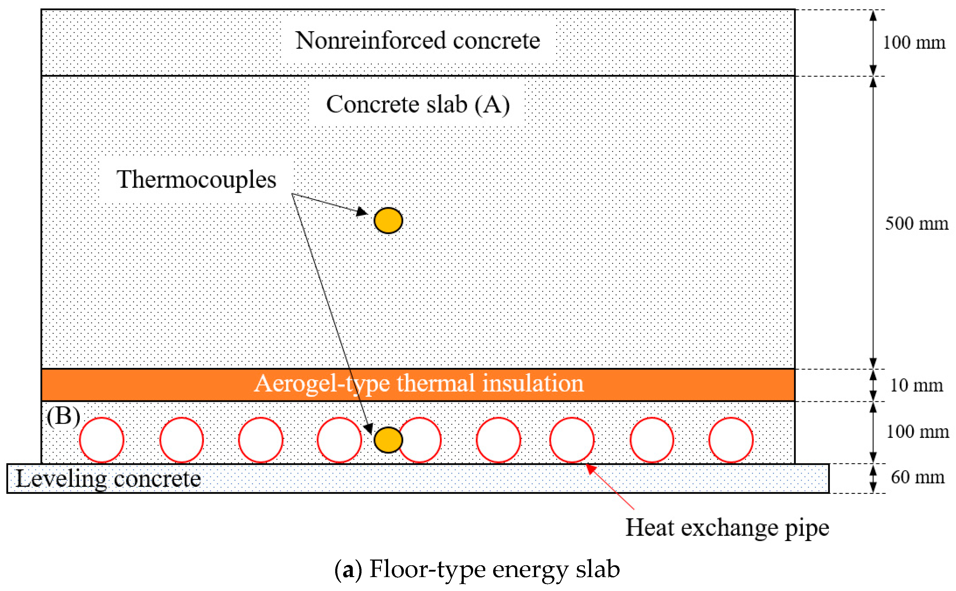
| Floor-type energy slab | 1 (Figure 3a) | Concrete slab above aerogel-type thermal insulation ((A) in Figure 5a) | T-type thermocouple | T1A |
| Concrete slab possessing heat exchange pipe ((B) in Figure 5a) | T-type thermocouple | T1B | ||
| Wall-type energy slab | 2 (Figure 3b) | Concrete slab above aerogel-type thermal insulation ((C) in Figure 5b) | T-type thermocouple | T2C |
| Concrete slab possessing heat exchange pipe ((D) in Figure 5b) | T-type thermocouple | T2D | ||
| Strain gauge | S2D | |||
| 3 (Figure 3b) | Concrete slab possessing heat exchange pipe ((D) in Figure 5b) | T-type thermocouple | T3D | |
| Strain gauge | S3D | |||
| Type | Details |
|---|---|
| Bath capacity | 42 L |
| Power of heater/cooler | 4.0 kW/0.6 kW |
| Range of temperature capacity | −10 °C~98 °C |
| Temperature uniformity | 1 °C |
| Capacity of circulation pump | 20 L/min |
| Electric requirement | 220 VAC, 60 Hz |
| Type | Floor-Type Energy Slab in This Study | Floor-Type Energy Slab in Previous Study [23] |
|---|---|---|
| Heat exchange pipe material (diameter) | HDPE (25 mm) | |
| Total length of heat exchange pipe | 123 m | 85 m |
| Pitch | 400 mm | 300 mm |
| Installation area | 49.5 m2 | 25 m2 |
| Density of heat exchange pipe (Total length of heat exchange pipe/ Installation area) | 2.73 m/m2 | 3.4 m/m2 |
| Thermal conductivity of ground formation | 1.2 W/(m·K) | 2.05 W/(m·K) |
| Thermal conductivity of thermal insulation material | 0.02 W/(m·K) (Aerogel) | 0.018 W/(m·K) (Phenol foam (PF) board) |
| Average heat exchange amount (7 days) | 2260 W | 430 W |
| Average heat exchange amount per unit area | 45.7 W/m2 | 17.2 W/m2 |
Disclaimer/Publisher’s Note: The statements, opinions and data contained in all publications are solely those of the individual author(s) and contributor(s) and not of MDPI and/or the editor(s). MDPI and/or the editor(s) disclaim responsibility for any injury to people or property resulting from any ideas, methods, instructions or products referred to in the content. |
© 2023 by the authors. Licensee MDPI, Basel, Switzerland. This article is an open access article distributed under the terms and conditions of the Creative Commons Attribution (CC BY) license (https://creativecommons.org/licenses/by/4.0/).
Share and Cite
Lee, S.; Park, S.; Han, T.H.; Won, J.; Choi, H. Applicability Evaluation of Energy Slabs Installed in an Underground Parking Lot. Sustainability 2023, 15, 2973. https://doi.org/10.3390/su15042973
Lee S, Park S, Han TH, Won J, Choi H. Applicability Evaluation of Energy Slabs Installed in an Underground Parking Lot. Sustainability. 2023; 15(4):2973. https://doi.org/10.3390/su15042973
Chicago/Turabian StyleLee, Seokjae, Sangwoo Park, Taek Hee Han, Jongmuk Won, and Hangseok Choi. 2023. "Applicability Evaluation of Energy Slabs Installed in an Underground Parking Lot" Sustainability 15, no. 4: 2973. https://doi.org/10.3390/su15042973
APA StyleLee, S., Park, S., Han, T. H., Won, J., & Choi, H. (2023). Applicability Evaluation of Energy Slabs Installed in an Underground Parking Lot. Sustainability, 15(4), 2973. https://doi.org/10.3390/su15042973