Article

A Novel Modeling Approach for Soil and Rock Mixture and Applications in Tunnel Engineering

1
School of Civil Engineering, Guangdong Communication Polytechnic, Guangzhou 510650, China
2
Guangdong Province Communications Planning & Design Institute Group Co., Ltd., Guangzhou 510507, China
3
Ningxia Center for Research on Earthquake Protection and Disaster Mitigation in Civil Engineering, Ningxia University, Yinchuan 750021, China
4
School of Civil Engineering, The Guilin University of Technology, Guilin 541000, China
5
Civil Engineering College, North Minzu University, Yinchuan 750021, China
6
School of Civil Engineering, Qingdao University of Technology, Qingdao 266000, China
7
School of Management Science, Guizhou University of Finance and Economics, Guiyang 550025, China
8
College of Mining Engineering, Guizhou University of Engineering Science, Bijie 551700, China
*
Author to whom correspondence should be addressed.
Sustainability 2023, 15(4), 3077; https://doi.org/10.3390/su15043077
Submission received: 18 December 2022 / Revised: 30 January 2023 / Accepted: 2 February 2023 / Published: 8 February 2023
(This article belongs to the Special Issue The Development of Underground Projects in Urban Areas)

Abstract

:
Soil and rock mixtures are complicated geomaterials that are characterized by both continuity and discontinuity. A homogeneous model cannot take into consideration the interactions between rocks and soil, which could lead to misjudgments of the mechanical properties. To simulate the mechanical responses of soil and rock mixtures accurately, a stochastic generation approach to soil and rock mixtures was developed systematically in this study. The proposed approach includes the following three major steps: (1) a combined image filtering technique and multi-threshold binarization method were developed to extract rock block files from raw images. (2) The shapes and sizes of block profiles were controlled and reconstructed randomly using Fourier analysis. (3) A fast-overlapping detection strategy was proposed to allocate the rock blocks efficiently. Finally, models of soil and rock mixtures with a specific rock proportion can be generated. To validate the proposed approach, numerical models were established in tunnel engineering using the conventional homogeneous method and the proposed numerical method, respectively. In addition, a series of field tests on tunnel deformation and stress were conducted. The results showed that the proposed heterogeneous numerical model can model the mechanical response of the soil and rock mixtures well and is much more effective and accurate than the conventional homogeneous approach. Using the proposed numerical approach, the failure mechanism of a tunnel in a soil and rock mixture is discussed, and a reinforcement strategy for the surrounding rocks is proposed. The field tests results indicate that tunnel lining stress can be well controlled within the strength criterion by the proposed reinforcement strategy.

1. Introduction

Soil and rock mixture is a complicated and problematic geomaterial, which has distinguishable physical and mechanical properties from those of pure rocks and soils. The mixtures are widely distributed in nature and bring a lot of difficulties to project constructions due to their complicated inner structures and mechanical properties [1,2,3]. Previous research validates that the mechanical properties of soil and rock mixtures are affected by multiple factors such as rock block proportions, rock block shapes, rock size distributions, etc. [4]. Thus, their mechanical properties cannot be determined by either pure rock or soils [5]. At present, most numerical models consider soil and rock mixtures to be homogeneous geomaterials. However, these simple numerical models cannot accurately present the effects of irregular rock blocks, which may lead to misunderstandings about their mechanical properties [6]. Thus, it is necessary to develop a detailed numerical approach that could better consider rock inclusions to model the mechanical responses of soil and rock mixtures accurately.
To consider the influence of rock blocks, researchers have proposed various methods to reconstruct the microstructure of the soil-rock mixture. Napoli et al., [4,7] and Wang X et al., [8] used regular shapes, such as circles, triangles, or rectangles to simulate gravel blocks. Xu et al., [9] used arbitrary convex polygon and ellipse shapes instead. In contrast, Nie et al., [10] developed a stochastic algorithm to model irregular rock blocks by combining circular function and Fourier functions. Some other researchers used digital image processing technology to obtain block profiles directly [1,11]. Even though a solid foundation has been laid by current research results [11,12,13], there are two urgent problems to be solved. First, simple mathematical functions and regular polygons cannot well represent the profiles of realistic rock blocks [1,13]. Second, it is hard to conduct systematic parameter analysis through digital image processing [11]. The critical parameters, such as block content, particle size distribution and roughness cannot be quantitatively controlled during the digital image process.
As for the numerical analysis method, various approaches to modeling the mechanical responses of soil and rock mixtures have been taken, such as the Discrete Element Method (DEM), Finite Discrete Element Method (FDEM) and Finite Element Method (FEM). DEM uses bonded particle assembly to simulate the rock or soil mass, in which the failure and mechanical responses are modeled by the bonding status between particles. Wang X et al. [8,14,15] have validated the efficiency of DEM in simulating soil and rock mixtures with consideration of irregular block shapes. Nevertheless, the contact search, diagnosis, and updating of particles will significantly increase computing costs [16]. In addition, the fully discrete and discontinuous assumption may not be appropriate to characterize the soil and rock mixture [17,18,19,20]. FDEM is capable of retaining both the continuity and discontinuity of the geomaterials. In recent years, it has been considered a very promising numerical method to model the complex mechanical and failure processes of soil and rock mixtures [21,22,23,24]. With appropriate modeling, the mechanical and fracturing behaviors of complicated geomaterials can be simulated [12,25]. However, calibration of the micro-mechanical parameters of the FDEM can be rather tedious and time consuming. Lots of parameters can only be obtained by using the trial-and-error method, which is not rigorous [26]. Zhang P et al., [13,27] have managed to model the failure process of soil and rock mixture by introducing the concept of an equivalent fracturing zone into the FEM program. The realistic failing process can be also presented by using a continuum-based model. In addition, mechanical parameters adopted in the FEM program can be obtained directly from experimental tests. However, the realistic shape of rock blocks is still not well considered in the presented research [13].
From the above-mentioned research, it is apparent that two critical issues need to be appropriately addressed to model the mechanical responses of soil and rock mixtures accurately. First, realistic block profiles need to be considered and obtained for modeling. Second, a systematic program to generate soil and rock mixtures with controllable characteristics (i.e., rock proportion etc.,) should be developed to build a heterogeneous numerical model, such that the mechanical characteristics of soil and rock mixtures can be well presented. Thus, in this study, a combined algorithm is first designed to extract the block profile from real rock blocks efficiently and effectively by digital image processing technology. Then, discrete Fourier transform theory is employed to represent and control the shape characteristics of block profiles. By developing the overlapping the detection algorithm and FEM approach, the stochastic heterogeneous numerical model of soil and rock mixtures can be generated. Last but not least, the proposed numerical model is applied in tunnel engineering and validated through the field tests.

2. Methodology

2.1. Strategy to Obtain Realistic Block Profiles from Raw Images

To obtain realistic block profiles, digital image processing technology was adopted to extract block profiles from images that are taken on sites. However, the quality of raw images of soil and rock mixtures is hard to control. Many factors, such as light, spots, and vegetative cover could affect the quality of images, which increases the difficulty of extracting block profiles. In addition, the single-pixel threshold may not be able to distinguish the realistic block profiles from a background whose color is close to that of the rock block. Therefore, a series of image computational algorithms were designed in this study to better extract the block profiles from the raw images.
  • Combined image filtering technique
Traditional noise filtering techniques, such as the averaging filtering method, median filtering, and Gaussian filtering method, cannot eliminate the noise of raw images effectively during the block profile extraction process. For instance, the Gaussian filtering method cannot preserve the boundary information of rock blocks when filtering the image noise. To obtain better noise filtering results, a combined noise filtering method is proposed in this study. The filtering process is usually conducted within calculation regions, as shown in Figure 1. First, the pixel value g ( i 0 , j 0 ) is calculated using a bilateral filtering approach, which can be expressed by [28,29]:
g ( i 0 , j 0 ) = ( i , j ) R w ( i , j ) f ( i , j ) ( i , j ) R w ( i , j )
where f ( i , j ) is the original pixel value, R represents the filtering regions and w ( i , j ) is the weight indexes, which are determined by [29]:
w ( i , j ) = w r ( i , j ) × w f ( i , j )   ; w r ( i , j ) = exp [ ( i i 0 ) 2 + ( j j 0 ) 2 2 σ r 2 ]   ; w f ( i , j ) = exp [ f ( i i 0 ) 2 + f ( j j 0 ) 2 2 σ f 2 ]   ;
where σ r 2 is the square difference of pixel distances and σ f 2 is the square difference of pixel values.
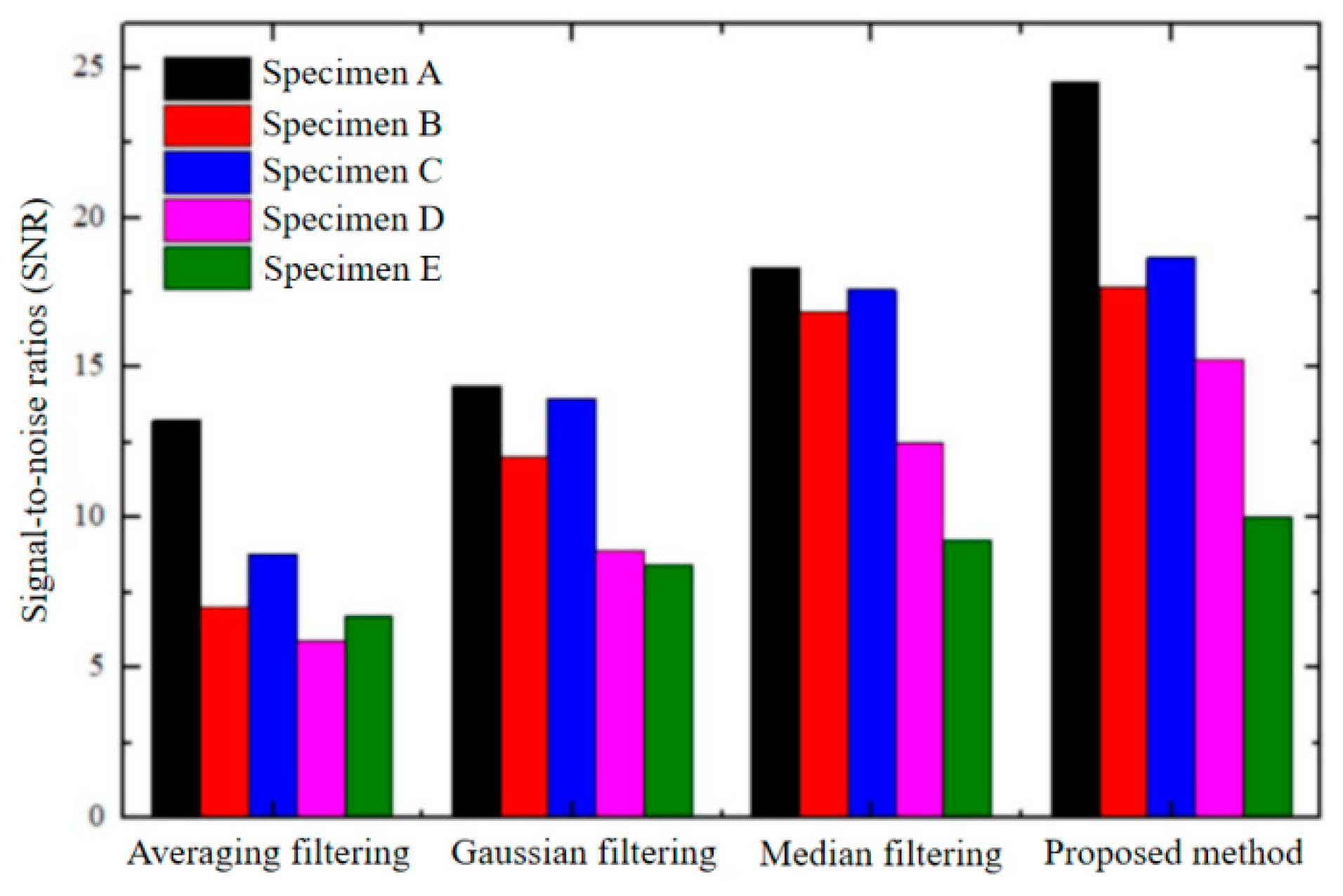
Test results indicate that the bilateral filtering approach can eliminate Gaussian noise with the block profiles being well retained because the pixel distance and pixel differences are both considered during the filtering process. However, it is still insensitive to the noise near pixel value of 255 or 0. To address this problem, the Median filtering method was combined with the bilateral filtering approach. Therefore, both noises can be effectively filtered. Five block images were adopted to verify the efficiency of the proposed combined filtering strategy. The signal-to-noise ratio was adopted as representative of the filtering effectiveness, which is calculated by [30]:
S N R = 10 log 10 [ i = 1 M j = 1 N f ( i , j ) 2 i = 1 M j = 1 N [ f ( i , j ) f ( i , j ) ] 2 ]   ;
where f ( i , j ) is the pixel value after filtering calculations.
The signal-to-noise ratios of the five images are presented in Figure 2. Test results indicate that noises would be effectively eliminated when the raw images undergo the combined filtering process. The combined filtering method has a better performance compared with those of the other conventional filtering methods.
2.
Method of image segmentation using multi-thresholds
After the noise filtering process, the next step is to identify the block profiles out of the images. This step is achieved by binarization according to the pixel values. However, it is hard to obtain the ideal block profiles with only one segmentation threshold, as the pixel differences are not consistent throughout the whole image. To obtain realistic block profiles from images, a local binarization strategy is proposed. The images were segmented evenly into nine small regions first. Then, binarization was conducted in each small region using its own segmentation threshold obtained using the Otsu method [31]. In this case, the influence of uneven light and shadows on rock block profile extractions can be greatly reduced. The extraction process of rock block profiles is presented in Figure 3. As can be seen, by combing the filtering technique and the image segmentation strategy, the proposed rock profile extraction methodology can obtain realistic profiles of the rock blocks effectively and efficiently. Note that, it is suggested to place the rock block in the center of the images to obtain an ideal extraction results. Therefore, the raw images should be appropriately prepared and selected when conducting the proposed profile extraction method.

2.2. Methodology to Generate Stochastic and Realistic Soil and Rock Mixture

To generate stochastic and realistic soil and rock mixture, several methodologies need to be developed. First, massive stochastic and realistic rock profiles need to be generated to offer the basic block profile data for model generation. Second, the size distribution of rock profiles should be quantitatively controlled. Third, an efficient overlap detection method is required to allocate the rock block into the specific domain. In this section, each method is introduced in detail.

2.2.1. Mathematical Representation of Rock Profile Using Fourier Analysis

To control the block sizes and generate massive similar block profiles, Fourier analysis was adopted to continuously present and reconstruct the block profiles. To conduct Fourier analysis, the block profile was discretized into a number of discrete segments, as shown in Figure 4. The original point was determined by the centroid of the block profile. A polar coordinate was adopted to represent the position of each point on the profile. Therefore, the block profiles can be transformed into a one-dimensional signal with the polar angle being the X-axis and the polar diameter being the Y-axis, which is presented on the right of Figure 4.
By conducting the Fourier analysis, the rock block can be presented by:
r i ( θ i ) = r 0 + n = 1 N / 2 [ A n cos ( n θ i ) + B n sin ( n θ i ) ]
where r 0 is the average of polar diameters, N is the total number of discrete points, n is the order of harmonics, A n and B n are Fourier harmonics, which determine the amplitude of the harmonics, which can be calculated by:
A n = 1 N i = 1 N [ r i cos ( n θ i ) ] B n = 1 N i = 1 N [ r i sin ( n θ i ) ]
Equation (4) can be rewritten as:
r i ( θ i ) r 0 = 1 + n = 1 N / 2 [ D n sin ( n θ i + φ n ) ]
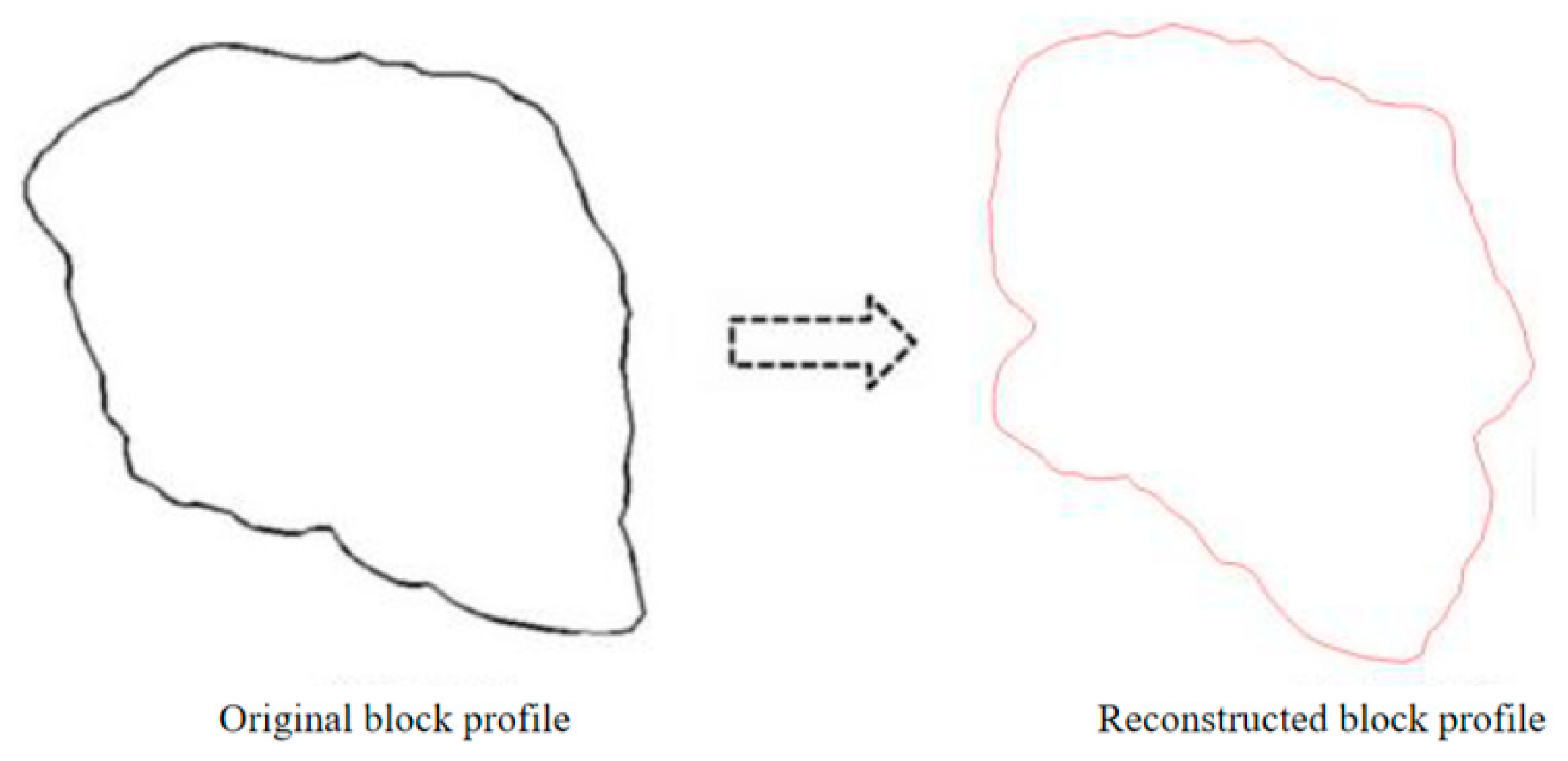
where D n = A n 2 + B n 2 / r 0 , sin φ n = A n / A n 2 + B n 2 , cos φ n = B n / A n 2 + B n 2 . The index Dn controls the main characteristics of the block profiles; whereas, φ n will influence the local features of the block profiles. Equation (6) will normalize the block size with the average diameter being 1. In this case, the block size can be controlled using a scaling parameter. In addition, stochastic block profiles with main characteristics being retained can be generated by replacing the φ n with a random value between [ π , π ] . The reconstructed and original block profiles are presented in Figure 5. Then, using the proposed method, massive similar rock blocks can be generated effectively and efficiently. In addition, a block morphology database of stochastic rock block profiles with various shape characteristics can be established.

2.2.2. Methodology to Approach Real Size Distribution of Rock Blocks

To control the size distribution of rock blocks, the probability density distributions of the target gradation of rock blocks should be given first, as shown in Figure 6. For each rock block, the block shape was first chosen from the established block morphology database. Then, the block size was randomly determined based on the obtained probability density distribution of the target size distribution (as shown in Figure 6). The fetch process of block morphology will be terminated when the target void proportion is reached. Then, the collected rock blocks would share the consistent size distribution of the target one, as shown in Figure 6.

2.2.3. Strategy to Conduct Overlap Detection among Rock Blocks

To allocate the block profiles into a specific domain, overlap detection among the block profiles should be conducted. To accelerate the allocation process, the rock blocks are enveloped with circles. As the overlap detection among particles only needs one calculation, the existing rock blocks that are close to the newly generated rock blocks are identified through the overlap detection among the circles, as shown in Figure 7.
The overlapped circles indicate that the existing rock blocks have the potential to overlap with the newly generated rock block. Thus, further overlap detection should be conducted among the irregular rock blocks. A quick example is presented in Figure 8. Owing to the Fourier analysis, both newly generated rock A and existing rock B can be presented with functions R A ( φ )   and   R B ( φ ) , respectively. As shown in Figure 8, if the length O A P B is larger than R i A ( φ i ) for each point on rock B, rock A has no contact with rock B. Once there is a point on rock B that satisfies O A P B < R i A ( φ i ) , rock A overlaps with rock B, as shown on the right of Figure 8. In this case, a random position would be generated once again for rock A to conduct a second round of overlap detection until the newly generated rock block is allocated within the domain. The same overlap detection method can be also be adopted to judge the relative position between the newly generated rock block and the boundaries. The allocation and overlap detection will be terminated once the desired rock block proportion is archived.

2.2.4. Systematic Approach to Generate Soil and Rock Mixtures with Specific Characteristics

  • Based on the obtained realistic block profiles, Fourier analysis, and overlap detection algorithm, the models of soil and rock mixture with a specific rock proportion and gradation can be generated effectively and efficiently. The process is listed as follows.
  • Given the shape features of target block inclusions, appropriate block morphology can be chosen from the block morphology database. Considerable stochastic block morphology can be generated efficiently using Fourier analysis.
  • Taking a rectangular region for instance, the volume of total blocks is determined based on a given inclusion content and a region’s volume. By referring to the gradation calculation method proposed in Section 2.2.2, sizes for each irregular inclusion can be obtained. Then, the chosen inclusions are scaled to approach the target size distribution.
  • The obtained rock blocks are then allocated to the rectangular regions from large to small with the help of the designed overlap detection method proposed in Section 2.2.3. A quick example and flowchart are presented in Figure 9.

2.3. Application of the Developed Method in Numerical Analysis of Tunnel Engineering

2.3.1. Generation of Numerical Models Using Proposed Method

In this section, the developed numerical method is applied to analyzing the mechanical responses of tunnel engineering. In addition, both the conventional FEM model and field tests were also conducted to offer a comparison to the proposed method. A tunnel in the southwest of China was adopted as the modeling object, which is located to the east of Lake Chenghai in Yunnan province at an altitude of 1869.95 m. The entrance and exit of the tunnel are covered by thick residual soils and rock mixtures, which are illustrated in Figure 10. As can be seen, massive rock blocks can be observed at the entrance and exits of the tunnel. Since the rock blocks found in the field are almost all limestone, the mechanical properties of the rock blocks adopted the same parameters as shown in Table 1. The variance in material properties of rock blocks is not considered in this study. The soil is mainly red clay that is moderately wet. Details of the mechanical properties of the rock mixture are presented in Table 1.
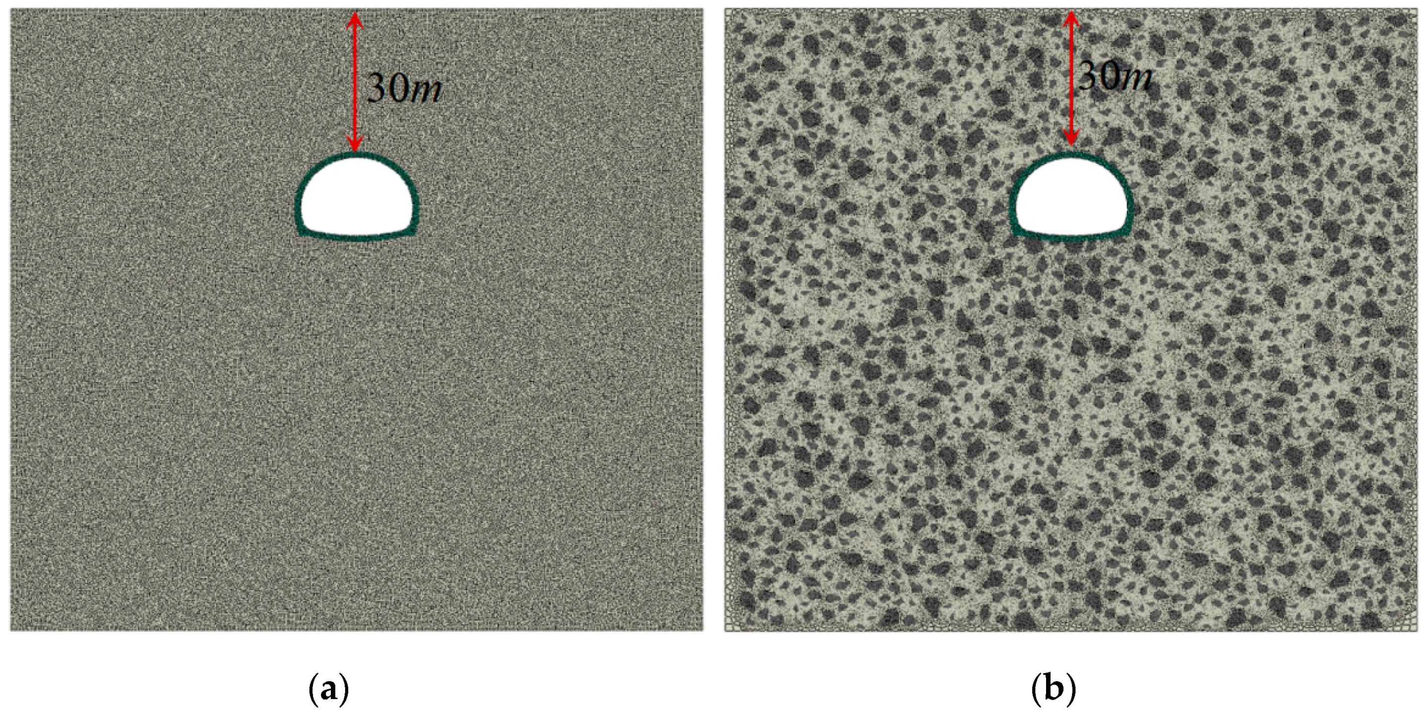
The numerical models generated by the conventional FEM and the proposed method are presented in Figure 11. The buried depth is 30 m. The boundaries on the left and right are fixed in the X direction; whereas, the bottom of the model is fixed in the Y direction. Because the soil and rock mixture is loosely packed, tectonic stress was not considered during the numerical analysis.
The parameters for the different numerical models are presented in Table 1. Mechanical properties of soil, rocks, lining structures, etc., were obtained from the field tests. The equivalent homogeneous parameters for the soil and rock mixture are referred to in existing studies conducted by Zhang et al., [27]. The Coulomb friction model was adopted to address the interactions between the lining and the soil.

2.3.2. Field Monitoring and Testing for Model Validation

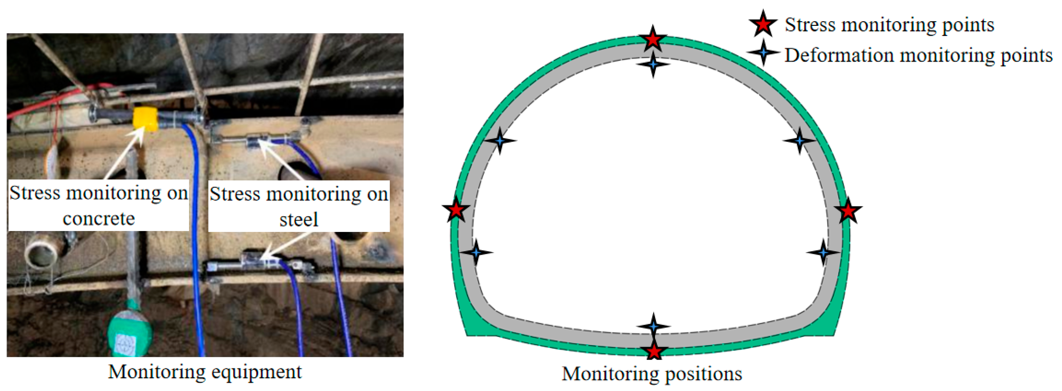
To understand the real deformation characteristics and stress distribution of the tunnel structures, field tests were also conducted on the initial support of the tunnel. The monitoring equipment and positions are presented in Figure 12. The sensors were fixed on the I-shaped steel and reinforcing steel mesh to monitor the stress of the steel and the concrete, respectively. Both sensors consist of vibrating wire stress meters, which have a measuring range of ±1500 μ ε and a sensitivity of 1 μ ε . The sensors for testing I-shaped steel were placed on the surface of the steel; whereas, the sensors for testing concrete are designed to be buried inside concrete. Four critical monitoring points were selected, as shown on the right of Figure 12. In addition, the deformations of critical positions of initial support were also tested in the field. The detailed monitoring positions are also presented on the right of Figure 12.

3. Results and Discussion

3.1. Deformation Comparison between Numerical Models

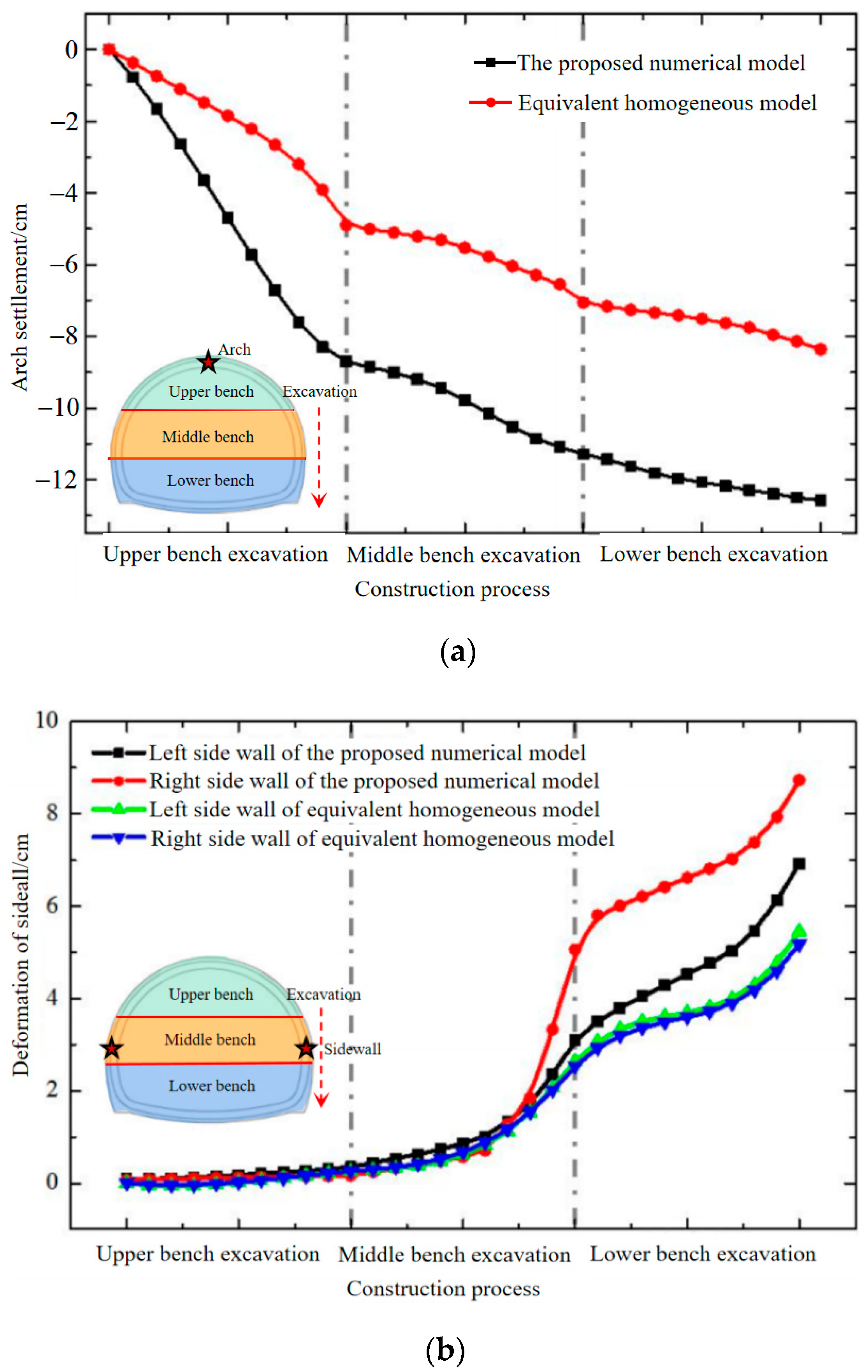
To compare the numerical results of the equivalent homogeneous model and the proposed heterogeneous model, deformations of surrounding rocks are both presented in Figure 13. The tunnel arch of both numerical models is presented in Figure 13a, and the deformations of the side walls are presented in Figure 13b. The tunnel excavation process is divided into three stages (i.e., excavation of upper, middle and lower bench), as shown in Figure 13. As it can be seen, notable increases in deformations are observed in both numerical models. However, the deformation results of the proposed heterogeneous model are much larger than those of the homogeneous model either at the tunnel arch or on the side walls. As shown in Figure 13a, the arch settlement in the heterogeneous model shows faster development and a more nonlinear evolution trend. Furthermore, unlike the symmetrical deformations on the side walls obtained from the homogeneous model, the deformations on the left and right side walls are rather different and asymmetric in the heterogeneous model due to the stochastic distribution of rock blocks, as shown in Figure 13b. In general, large deformations are observed for each construction process using the proposed heterogeneous model. This indicates that the equivalent homogeneous model would underestimate deformations of surrounding rock as it overestimates the strengthening effects of rock blocks. The calculation results of the heterogeneous model are much more conservative compared with those of the equivalent homogeneous model.

3.2. Comparison of Plastic Zones between Numerical Models

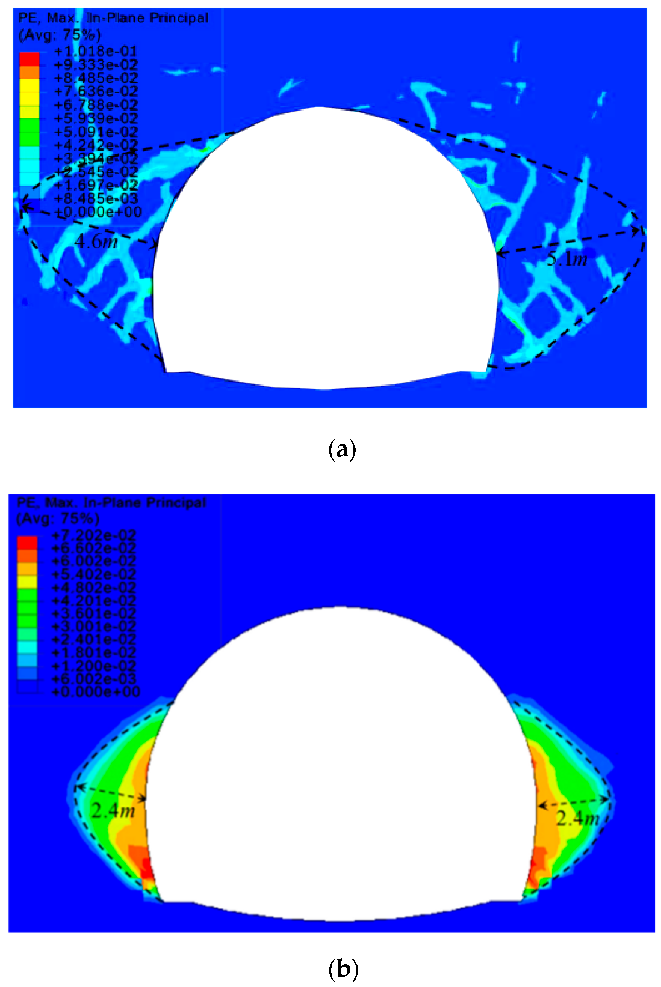
The final plastic zones of the proposed heterogeneous model are presented in Figure 14a. Various plastic shearing bands are observed in the heterogeneous numerical model, which offers multiple failure paths for the surrounding rocks. The connected plastic shearing bands concentrate on the side wall of the tunnel, which would lead to final collapse. It was noticed that the plastic strain concentrates on the interface between the rock block and the soil, which is mainly caused by the distinctive difference in stiffness between the rock block and the soil. It is inferred that the proposed heterogeneous model can accurately simulate interactions among rock blocks and soil which are directly ignored by the equivalent homogeneous model. In addition, the sliding and shearing characteristics are much more prevalent in the proposed heterogeneous models than in those of the equivalent homogeneous model. As the influence of the rock blocks is well considered, the plastic zones and depth obtained from the proposed model are 58.2 m2 and 5.1 m, respectively. However, the plastic zones and depth obtained from the homogeneous model are only 19.2 m2 and 2.4 m, respectively, which are much smaller.
Field investigations also validate that side walls are vulnerable structures that may be damaged by extensive deformations. Large deformations and local failure of the initial support are observed on the side walls of the real tunnel, as shown in Figure 15. Due to the stochastic distribution of rock blocks, the damage degree also varies between the left and right side walls, which is consistent with the numerical findings of the proposed heterogeneous model. It has been proved that the numerical results obtained from the proposed method are closer to the realistic deformation and failure characteristics of tunnel engineering buried in soil and rock mixtures.
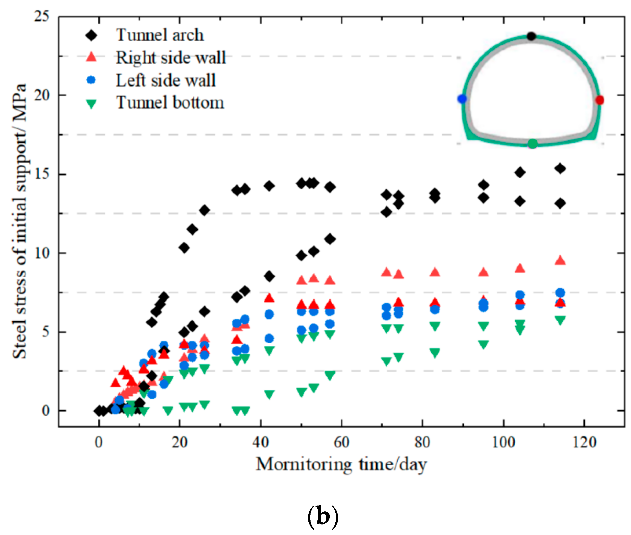
Stresses on initial support are also monitored during the construction process, which is illustrated in Figure 16. As mentioned in Section 2.3.2, two kinds of vibrating wire stress meter were installed in the lining structure to monitor stress evolution. In general, the stresses on the tunnel arch were highest; whereas, the stresses on the tunnel bottom are lowest. The stresses on the left and right side walls are inconsistent, and the stresses on the right side are larger in general. This proves that rock blocks would cause asymmetric stress distribution in the tunnel, which is unfavorable to tunnel stability. The same phenomenon can also be inferred from the deformation characteristics of the proposed heterogeneous numerical model, which proves the efficiency of the proposed numerical method from another aspect.

3.3. Comparison with the Field Monitoring Results

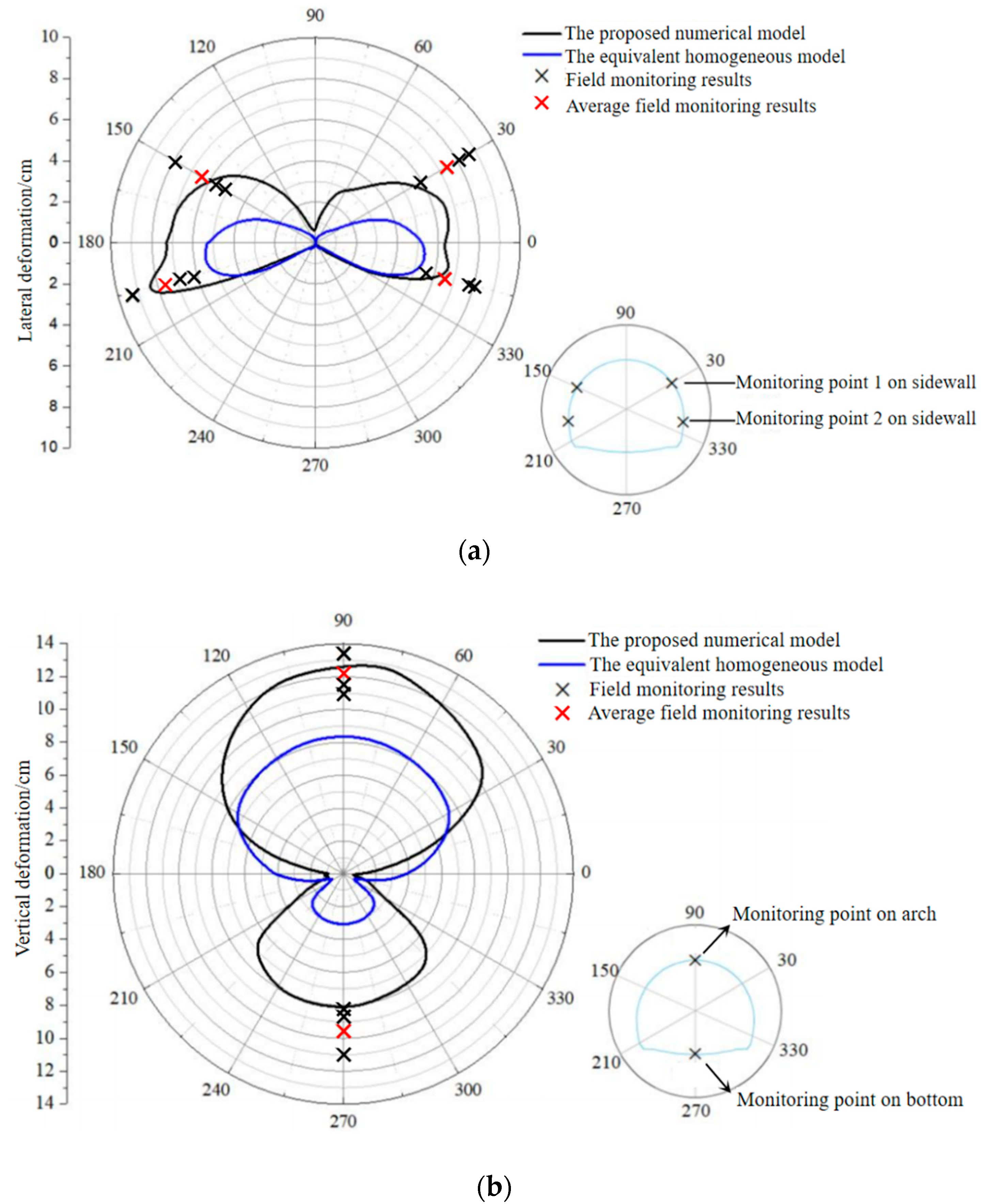
Final lateral and vertical deformations of surrounding rocks of the proposed heterogeneous numerical model, equivalent homogeneous model, and the field tests are illustrated in Figure 17. As can be seen, the deformation results obtained from the proposed numerical model are closer to the field test results. The average relative errors are 11.9% in lateral deformation and 10.2% in vertical deformation. Based on the test and numerical analysis, the two ends of the side walls show extensive deformation during the tunnel excavation, which should be closely monitored and strengthened to guarantee tunnel safety. The settlement of the tunnel arch and bump of the tunnel bottom is also overwhelming in both the numerical and the test results. It was noticed that the tunnel bottom deformations of the proposed numerical method are much larger than those of the homogeneous model. Field investigation also validates that the rise of the tunnel bottom would cause the fracturing of the filling layer on the tunnel bottom, which should also be closely monitored.
Based on the comparison between numerical results and field test results, it can be concluded that the proposed heterogeneous numerical model can accurately model the mechanical response of the soil and rock mixtures. It is much more effective and accurate than the conventional homogeneous approach. As a result, the validated numerical models are considered to be valid and will be used in the following simulations.

3.4. Failure Mechanism and Reinforcement Strategy of the Tunnel in Soil and Rock Mixture

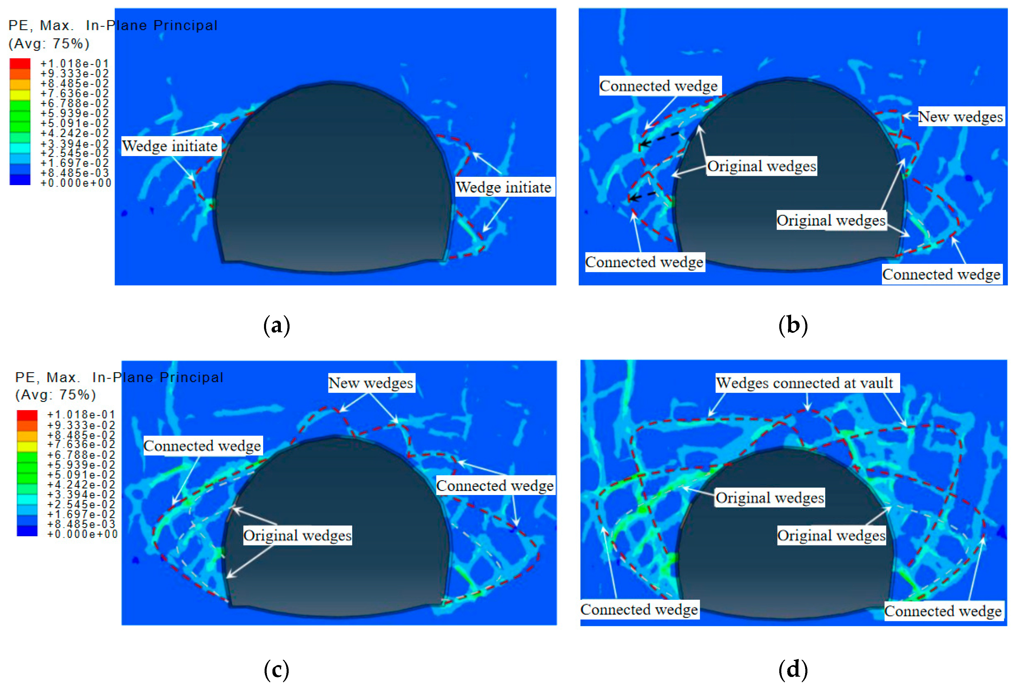
To investigate the failure mechanism of the tunnel in soil and rock mixtures, four numerical models considering various support stiffnesses were generated using the proposed method. The stiffness was set at 1.5, 1, 0.5, and 0 (i.e., no support) times the designed stiffness. The plastic deformations of surrounding rocks were analyzed for each model using the proposed method, which are illustrated in Figure 18. It is inferred that the failure of the tunnel in soil and rock mixtures consists of four stages.
  • As shown in Figure 18a, the plastic deformation is observed only in limited regions of the side walls when the stiffness of support is 1.5 times the designed value. Most plastic deformations initiate at the interfaces between soil and rocks and have a great tendency to expand and connect with each other. Only some small wedges are formed by the limited plastic deformations at this stage. Note that these wedges are loose and have a great tendency to collapse. The maximum plastic deformation is only 0.08, which indicates that the surrounding rocks are still stable at this stage.
  • With decreasing stiffness, the plastic deformation would develop rapidly along the interfaces between blocks and matrix. A larger wedge is formed based on the original small wedges. The plastic strain increases to 0.1 with a larger area of surrounding rocks being loosened. As with the different spatial distribution of rock blocks, the plastic deformation is also asymmetric. The loosened area of surrounding rocks on the left is much larger than that of those on the right of the tunnel.
  • With the support stiffness further weakened, the plastic deformation at the side walls develops further, and a larger shear wedge structure begins to form. In addition, the plastic shear deformation extends to the vault, which has a chance to connect the left and right plastic zones. At this time, the peak value of plastic strain is raised to 0.14, and the local shear failure already appears at the side wall of the tunnel.
  • As the initial support is completely removed, the plastic zones of the left and right surrounding rocks have been connected, and the failure zone around the tunnel is completely formed. At this time, the peak value of plastic strain rapidly increases to 0.19. At this stage, the shearing failure paths are well-developed, and the overall failure of the surrounding rock is inevitable.
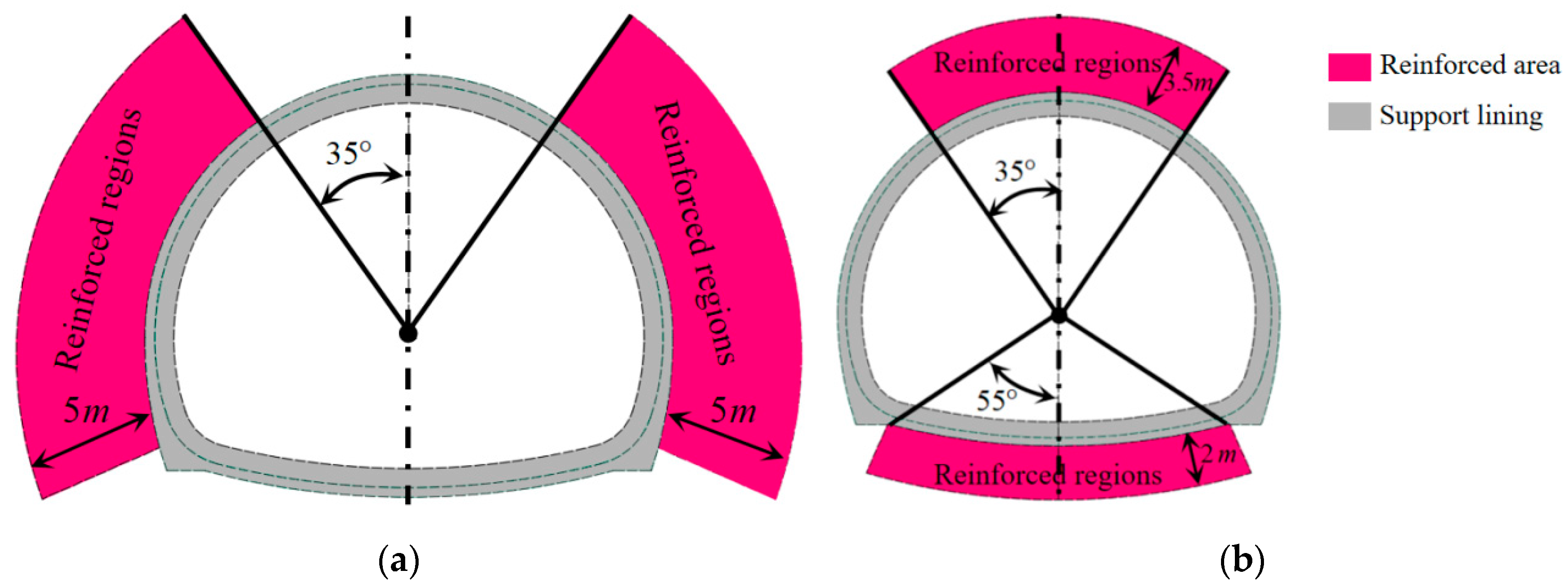
Based on the failure analysis above, it can be concluded that plastic deformation of the soil-rock mixture initiates first at the tunnel side walls and arch waist. Shearing failure would be observed at the side walls first and then develop rapidly if the support system decays, which would lead to the overall collapse of the tunnel in the end. However, if the critical regions, such as surrounding rocks at the tunnel side walls and vault, can be protected in advance, the development of surrounding rock plastic deformation would be effectively controlled. Therefore, considering both the distribution characteristics of plastic deformation of surrounding rock and the field investigations, reinforced regions have been suggested and defined to improve the stability of the tunnel during excavation, which are illustrated in Figure 19. As shown in Figure 19, the reinforced depth at the side walls is 5 m; whereas, the reinforced depths at the vault and the bottom of the tunnel are 3.5 m and 2 m, respectively.
By adopting the reinforced strategy proposed in Figure 19, the surrounding rocks of the real tunnel were reinforced by grouting in the defined regions during the construction process. To evaluate the effectiveness of the strengthening, the concrete stress of the initial support was monitored after the reinforcements were conducted. The monitoring results are illustrated in Figure 20. It was noticed that the stress remained stable quickly after the support was constructed. In addition, the concrete stress was lower after reinforcements. This indicates that a defined reinforcing strategy can effectively increase the stability and safety of the tunnel during the construction process. In practice, it was also found that tunnel deformation could be more controllable if the heading face among the benches was within 3 m. Feet-lock bolts with a length of 5 m and a diameter of 25 mm are suggested to be adopted after the excavation of the middle and lower benches. In addition, double-layer support could be considered when the deformation is hard to control.

4. Conclusions

In this study, a systematic stochastic approach was developed to simulate soil and rock mixture. A series of computational algorithms were developed to obtain and reconstruct realistic block profiles first. With help of a designed overlap detection method, a model of soil and rock mixtures with specific characteristics can be generated conveniently. The results showed that the proposed model can accurately model the mechanical response of soil and rock mixtures. Then, the failure mechanism of a tunnel in soil and rock mixture and a reinforcement strategy were discussed. The conclusions drawn are as follows:
  • Realistic rock block files can be obtained from raw images by combining the designed image filtering technique and multi-threshold binarization method. Using Fourier analysis and the fast-overlapping detection strategy, a numerical model of soil and rock mixture with specific internal characteristics can be generated effectively and efficiently.
  • The proposed heterogeneous numerical model has been verified as being effective in modeling the mechanical and failure characteristics of soil and rock mixtures by comparing it with the conventional homogeneous numerical model. In addition, the numerical results of the proposed numerical method were in good agreement with the field test results from deformation characteristics to failure patterns, wherein the rock blocks mainly consisted of limestone.
  • Considering the distribution characteristics of plastic deformation in surrounding rock and field investigations, reinforced regions of surrounding rocks were suggested and defined. The reinforced depth at the side walls was 5 m; whereas, the reinforced depths at the vault and the bottom of the tunnel were 3.5 m and 2 m, respectively. The reinforcement strategy was proven to be effective by the field test results.
  • It is admitted that the obtained conclusions are mainly for areas in the west of China such as the Ningxia area and Yunnan province. In addition, the interface effects among the rock blocks and matrix have not been considered in the proposed method. Thus, the proposed model would not be suitable to model situations wherein interface effects cannot be neglected. In future work, the effects of interfaces would be considered by introducing zero-thickness cohesive elements to model the interfaces so that the proposed model could be further improved.

Author Contributions

Conceptualization, X.Z., H.L. and K.X.; Methodology, X.Z.; Software, H.L., R.Y., Z.M. and Y.W.; Validation, X.Z. and H.L.; Formal analysis, X.Z., H.L., K.X., Z.S. and H.W.; Investigation, H.L., K.X., R.Y., Z.M., Y.W. and Z.S.; Resources, X.Z., W.Y., Z.M. and H.W.; Data curation, H.L., W.Y. and Z.M.; Writing—original draft, X.Z.; Writing—review & editing, H.L., K.X., W.Y., Y.W., Z.S. and H.W.; Supervision, H.L. and R.Y.; Project administration, W.Y. and R.Y. All authors have read and agreed to the published version of the manuscript.

Funding

This work was financially supported by the Ningxia Key Research and Development Program of China (Grant No. 2021BEG03118).

Institutional Review Board Statement

Not applicable.

Informed Consent Statement

Not applicable.

Data Availability Statement

Data is available by contacting the corresponding author.

Conflicts of Interest

The authors declare no conflict of interest.

References

  1. Lin, Y.; Yin, Z.-Y.; Wang, X.; Huang, L. A systematic 3D simulation method for geomaterials with block inclusions from image recognition to fracturing modelling. Theor. Appl. Fract. Mech. 2021, 117, 103194. [Google Scholar] [CrossRef]
  2. Lin, Y.; Wang, X.; Ma, J.; Huang, L. A finite-discrete element based appoach for modelling the hydraulic fracturing of rocks with irregular inclusions. Eng. Fract. Mech. 2022, 261, 108209. [Google Scholar] [CrossRef]
  3. Ma, J.; Chen, J.; Guan, J.; Lin, Y.; Chen, W.; Huang, L. Implementation of Johnson-Holmquist-Beissel model in four-dimensional lattice spring model and its application in projectile penetration. Int. J. Impact Eng. 2022, 170, 104340. [Google Scholar] [CrossRef]
  4. Napoli, M.L.; Barbero, M.; Ravera, E.; Scavia, C. A stochastic approach to slope stability analysis in bimrocks. Int. J. Rock Mech. Min. Sci. 2018, 101, 41–49. [Google Scholar] [CrossRef]
  5. VTran, D.; Meguid, M.; Chouinard, L. A fifiniteediscrete element framework for the 3D modeling of geogride soil interaction under pullout loading conditions. Geotext. Geomembranes 2013, 37, 1–9. [Google Scholar] [CrossRef]
  6. Zheng, K.; Shi, C.; Lin, Y.; Lei, M.; Liu, J. Transfer station cracks induced by cutting anchor cables and crack stabilization: A case study. Eng. Fail. Anal. 2021, 126, 105460. [Google Scholar] [CrossRef]
  7. Napoli, M.L.; Milan, L.; Barbero, M.; Scavia, C. Identifying uncertainty in estimates of bimrocks volumetric proportions from 2D measurements. Eng. Geol. 2020, 278, 105831. [Google Scholar] [CrossRef]
  8. Wang, X.; Nie, Z.; Gong, J.; Liang, Z. Random generation of convex aggregates for DEM study of particle shape effect. Constr. Build. Mater. 2021, 268, 121468. [Google Scholar] [CrossRef]
  9. Xu, W.-J.; Hu, L.-M.; Gao, W. Random generation of the meso-structure of a soil-rock mixture and its application in the study of the mechanical behavior in a landslide dam. Int. J. Rock Mech. Min. Sci. 2016, 86, 166–178. [Google Scholar] [CrossRef]
  10. Nie, Z.; Fang, C.; Gong, J.; Liang, Z. DEM study on the effect of roundness on the shear behaviour of granular materials. Comput. Geotech. 2018, 121, 103457. [Google Scholar] [CrossRef]
  11. Clarke, A.P.; Vannucchi, P. Structural anisotropy: Using image analysis to quantify block-in-matrix fabrics. J. Struct. Geol. 2020, 131, 103939. [Google Scholar] [CrossRef]
  12. Wang, P.; Yin, Z.-Y.; Wang, Z.-Y. Micromechanical Investigation of Particle-Size Effect of Granular Materials in Biaxial Test with the Role of Particle Breakage. J. Eng. Mech. 2022, 148, 04021133. [Google Scholar] [CrossRef]
  13. Zhang, P.; Lu, D.; Du, X.; Qi, J. A division method for shallow tunnels and deep tunnels considering soil stress path dependency. Comput. Geotech. 2021, 135, 104012. [Google Scholar] [CrossRef]
  14. Wang, X.; Liang, Z.; Nie, Z.; Gong, J. Stochastic numerical model of stone-based materials with realistic stone-inclusion features. Constr. Build. Mater. 2018, 197, 830–848. [Google Scholar] [CrossRef]
  15. Wang, X.; Gong, J.; An, A.; Zhang, K.; Nie, Z. Random generation of convex granule packing based on weighted Voronoi tessellation and cubic-polynomial-curve fitting. Comput. Geotech. 2019, 113, 103088. [Google Scholar] [CrossRef]
  16. Zheleznyakova, A.L. A cost-effective computational approach based on molecular dynamics for generating 3D packs of irregularly-shaped grains in a container of complex geometry. Powder Technol. 2021, 394, 403–423. [Google Scholar] [CrossRef]
  17. Yin, Z.-Y.; Wang, P.; Zhang, F. Effect of particle shape on the progressive failure of shield tunnel face in granular soils by coupled FDM-DEM method. Tunn. Undergr. Space Technol. 2020, 100, 103394. [Google Scholar] [CrossRef]
  18. Huang, G.; Zhang, S.; Xu, Y. A sphere-triangle contact model with complex boundary face problems. Appl. Math. Model. 2020, 93, 395–411. [Google Scholar] [CrossRef]
  19. Huang, G.; Tong, C.; Zhang, S.; Chen, X. A thermo-solid coupling model for disk discontinuous deformation analysis to simulate heating and stirring particles in rotary drums. Powder Technol. 2022, 402, 117326. [Google Scholar] [CrossRef]
  20. Wang, P.; Yin, Z.-Y.; Zhou, W.-H.; Chen, W.-B. Micro-mechanical analysis of soil–structure interface behavior under constant normal stiffness condition with DEM. Acta Geotech. 2021, 17, 2711–2733. [Google Scholar] [CrossRef]
  21. Lin, Y.; Wang, X.; Ma, J.; Huang, L. A systematic framework for the 3D finite-discrete modelling of binary mixtures considering irregular block shapes and cohesive block-matrix interfaces. Powder Technol. 2021, 398, 117070. [Google Scholar] [CrossRef]
  22. Lin, Y.; Li, C.; Ma, J.; Lei, M.; Huang, L. Effects of void morphology on fracturing characteristics of porous rock through a finite-discrete element method. J. Nat. Gas Sci. Eng. 2022, 104, 104684. [Google Scholar] [CrossRef]
  23. Yan, C.; Zheng, Y.; Huang, D.; Wang, G. A coupled contact heat transfer and thermal cracking model for discontinuous and granular media. Comput. Methods Appl. Mech. Eng. 2021, 375, 113587. [Google Scholar] [CrossRef]
  24. Yan, C.; Wei, D.; Wang, G. Three-dimensional finite discrete element-based contact heat transfer model considering thermal cracking in continuous–discontinuous media. Comput. Methods Appl. Mech. Eng. 2022, 388, 114228. [Google Scholar] [CrossRef]
  25. Yan, C.; Guo, H.; Tang, Z. Three-dimensional continuous-discrete pore-fracture mixed seepage model and hydro-mechanical coupling model to simulate hydraulic fracturing. J. Pet. Sci. Eng. 2022, 215, 110510. [Google Scholar] [CrossRef]
  26. Montoya-Araque, E.A.; Suarez-Burgoa, L.O. Automatic generation of tortuous failure surfaces in block-in-matrix materials for 2D slope stability assessments. Comput. Geotech. 2019, 112, 17–22. [Google Scholar] [CrossRef]
  27. Zhang, P.; Jin, L.; Du, X.; Lu, D. Computational homogenization for mechanical properties of sand cobble stratum based on fractal theory. Eng. Geol. 2018, 232, 82–93. [Google Scholar] [CrossRef]
  28. Luerkens, D.W. Theory and Applications of Morphological Analysis: Fine Particles and Surfaces; CRC Press: London, UK, 1991. [Google Scholar]
  29. Sudeep, P.; Niwas, S.I.; Palanisamy, P.; Rajan, J.; Xiaojun, Y.; Wang, X.; Luo, Y.; Liu, L. Enhancement and bias removal of optical coherence tomography images: An iterative approach with adaptive bilateral filtering. Comput. Biol. Med. 2016, 71, 97–107. [Google Scholar] [CrossRef]
  30. Russ, J.C. Computer Assisted Microscopy: The Measurement and Analysis of Images; Plenum Press: New York, NY, USA, 1990. [Google Scholar]
  31. Feng, Y.; Zhao, H.; Li, X.; Zhang, X.; Li, H. A multi-scale 3D Otsu thresholding algorithm for medical image segmentation. Digit. Signal Process. 2017, 60, 186–199. [Google Scholar] [CrossRef] [Green Version]
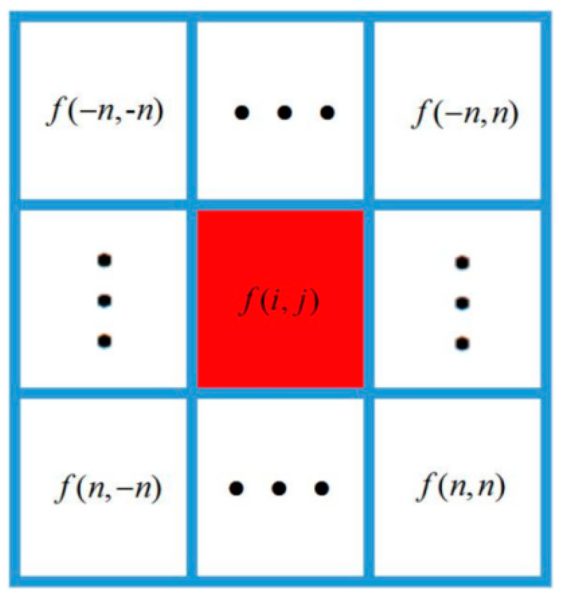
Figure 1. Calculation regions during the filtering process.
Sustainability 15 03077 g001
Figure 2. Test results of signal-to-noise ratio.
Sustainability 15 03077 g002
Figure 3. Extraction process of rock block profiles.
Sustainability 15 03077 g003
Figure 4. Discretization of block profile process.
Sustainability 15 03077 g004
Figure 5. Original and reconstructed block profiles.
Sustainability 15 03077 g005
Figure 6. Size distribution of rock blocks.
Sustainability 15 03077 g006
Figure 7. General overlap detection among rock blocks.
Sustainability 15 03077 g007
Figure 8. Detailed overlap detection between two rock blocks.
Sustainability 15 03077 g008
Figure 9. Two-dimensional stochastic soil-rock mixed model.
Sustainability 15 03077 g009
Figure 10. Soil and rock stratum of the tunnel in southwest China.
Sustainability 15 03077 g010
Figure 11. Two-dimensional tunneling model using conventional FEM and the proposed numerical method. (a) model using conventional FEM; (b) model using proposed numerical method.
Sustainability 15 03077 g011
Figure 12. Field test of the initial support structure.
Sustainability 15 03077 g012
Figure 13. The comparison of the numerical analysis. (a) Deformation analysis at the vault; (b) Deformation analysis at sidewalls.
Sustainability 15 03077 g013
Figure 14. Comparison of plastic zones. (a) Plastic zones of the proposed heterogeneous model; (b) Plastic zones of the homogeneous model.
Sustainability 15 03077 g014
Figure 15. Large deformations and failures of initial support on side walls.
Sustainability 15 03077 g015
Figure 16. Stress characteristics of initial support. (a) Steel stress of initial support; (b) Concrete stress of initial support.
Sustainability 15 03077 g016aSustainability 15 03077 g016b
Figure 17. Comparison of deformation of initial support. (a) Comparison of lateral deformation of initial support; (b) Comparison of vertical deformation of initial support.
Sustainability 15 03077 g017
Figure 18. Plastic deformation of surrounding rocks under various support stiffnesses. (a) Reinforced initial support (1.5 times); (b) Designed initial support (1 times); (c) Weakened initial support (0.5 times); (d) No support.
Sustainability 15 03077 g018
Figure 19. Reinforcing strategy. (a) Side walls; (b)Vault and bottom.
Sustainability 15 03077 g019
Figure 20. Evolution of concrete stress of initial support.
Sustainability 15 03077 g020
Table 1. Physical and mechanical parameters of numerical models.
MaterialElastic Modulus/MPaPoisson’s RatioCohesion
/MPa
Friction Angle/°
Model of the proposed heterogeneous model
Soil580.320.1228
Limestone20,0000.21040
Reinforcement area15000.20.430
Lining structures20,0000.2--
Model of the equivalent homogeneous model
Equivalent surrounding rocks750.30.1533
Reinforcement area15000.20.430
Initial support system20,0000.2--
Disclaimer/Publisher’s Note: The statements, opinions and data contained in all publications are solely those of the individual author(s) and contributor(s) and not of MDPI and/or the editor(s). MDPI and/or the editor(s) disclaim responsibility for any injury to people or property resulting from any ideas, methods, instructions or products referred to in the content.