Research on the Integration of a Natural Gas-Distributed Energy System into the Oilfield Facility in China


Abstract
:1. Introduction
2. Methodology
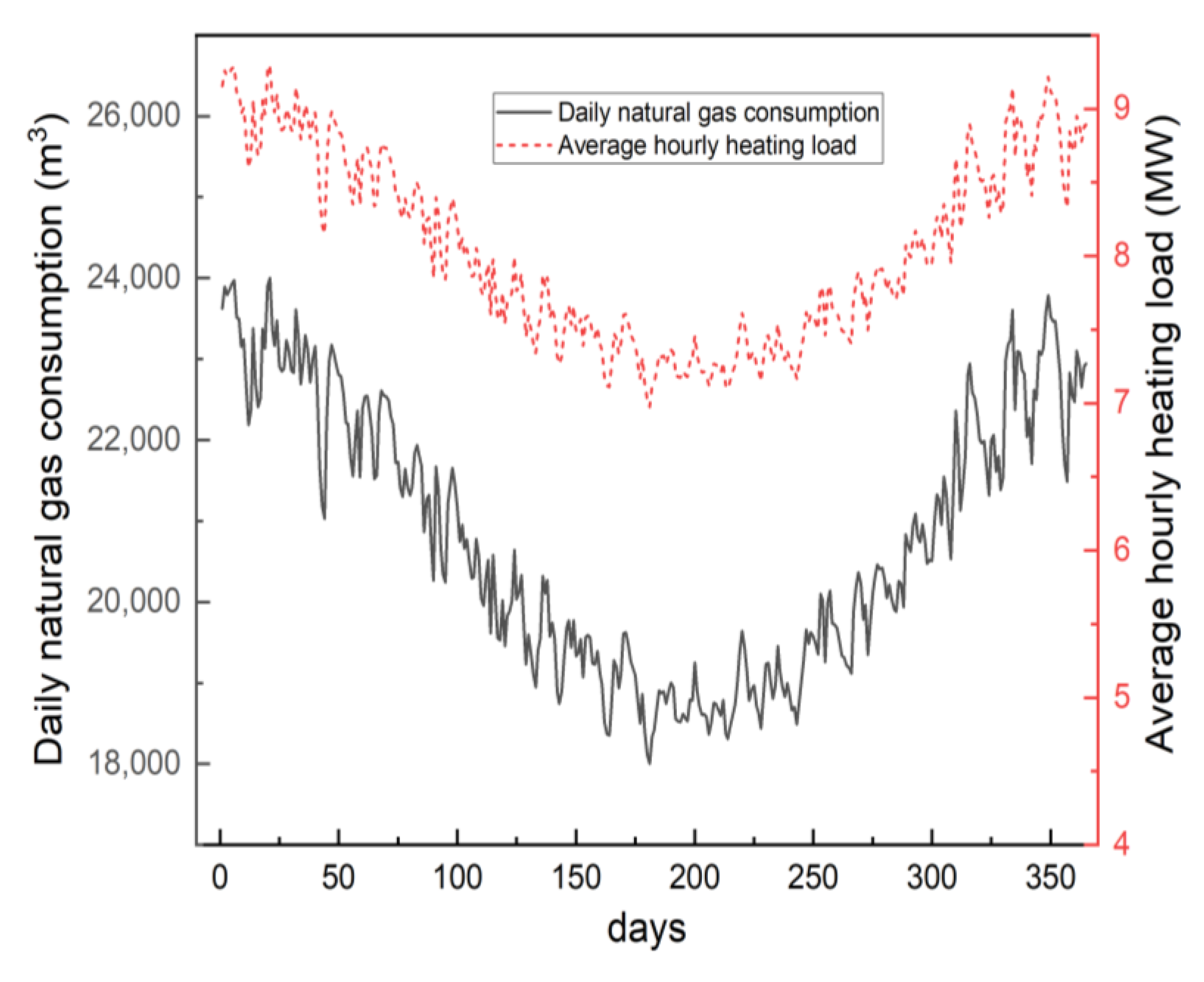
2.1. The Status of Energy Consumption of the Oilfield Facility
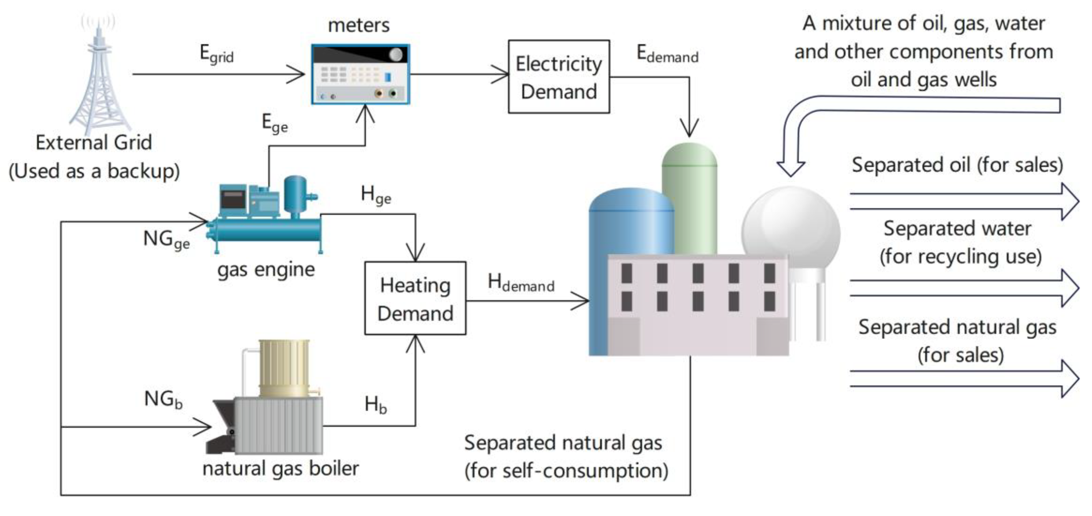
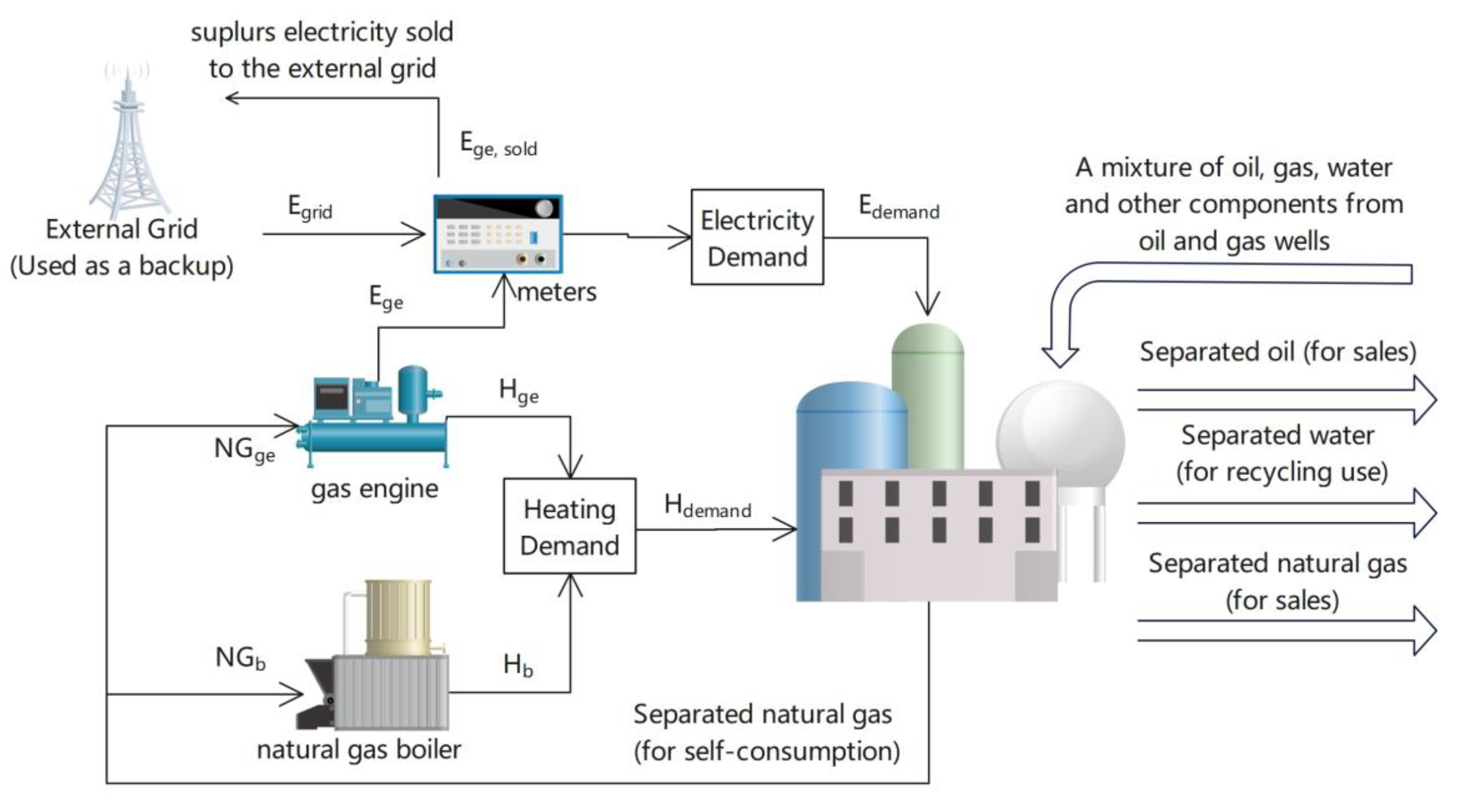
2.2. Energy Supply Method 1: Following the Electric Load (FEL)
2.3. Energy Supply Method 2: Following the Heating Load (FHL)
2.4. Natural Gas Components
3. Results and Discussion
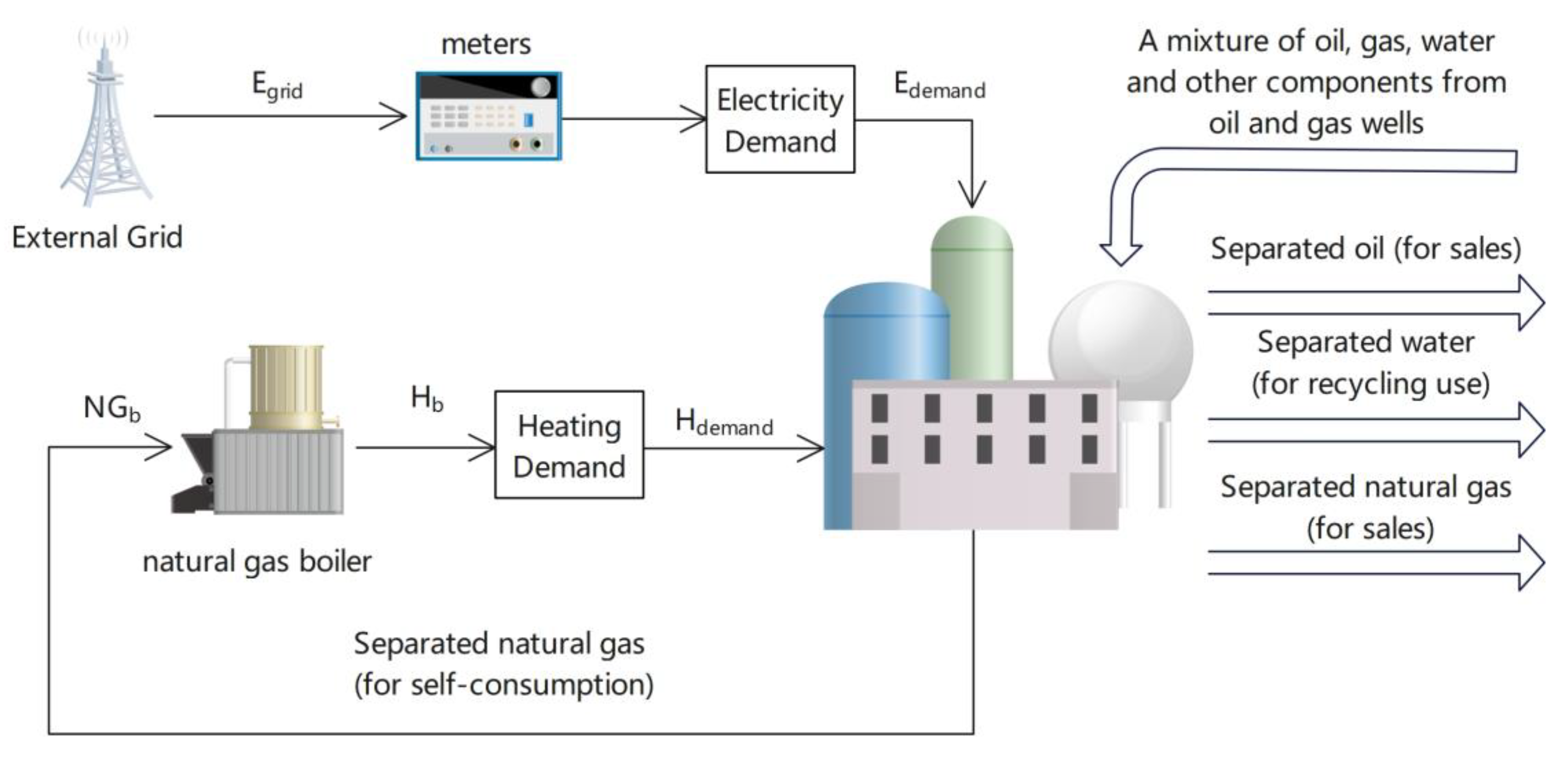
3.1. Basic Energy Supply Method
3.2. FEL
3.3. FHL
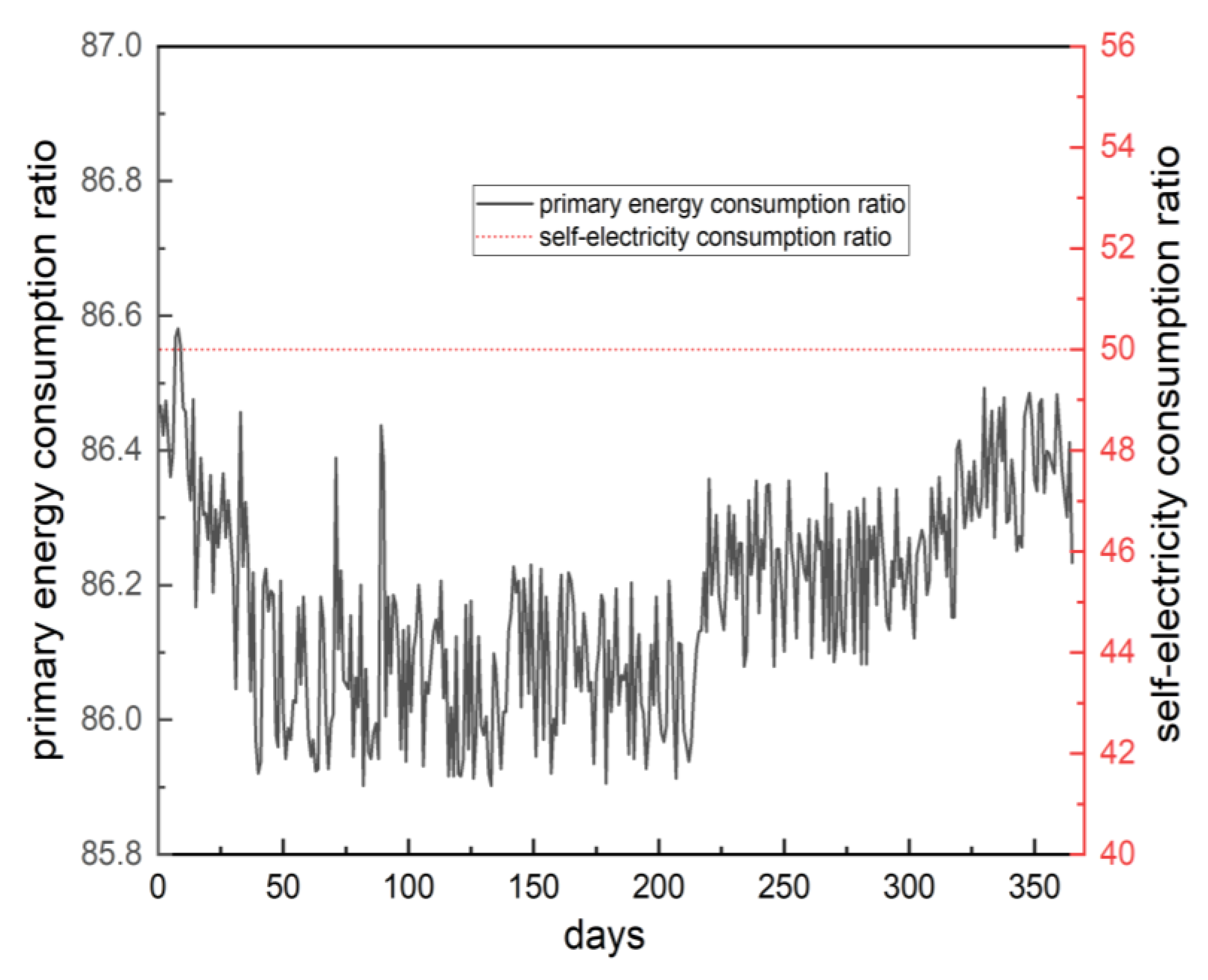
3.4. FHL-Restricted
4. Conclusions
- (1)
- The natural gas distributed energy system can significantly reduce the operating cost because the oilfield facility has a prominent price advantage over self-produced natural gas.
- (2)
- The economic performance of distributed energy systems is optimal when electricity can be sold to the external grid (FHL). However, distributed energy systems in China are subject to policy constraints and must simultaneously meet the requirements of the self-electricity and primary energy consumption ratios. Therefore, under the FHL-restricted mode, when the self-electricity consumption ratio of the gas engine is kept at 50%, the natural gas-distributed energy systems can meet policy requirements while achieving optimal carbon emission reductions and minimizing operating costs.
- (3)
- The increase in carbon emissions from the oilfield facility is mainly due to the gas engine’s sales of electricity to the external grid. The carbon emissions of the power supply by the gas engine are lower than the carbon emission from the grid supply. Therefore, although the operational carbon emissions of the oilfield facility increase, it can effectively reduce the carbon emissions of the grid supply.
Author Contributions
Funding
Institutional Review Board Statement
Informed Consent Statement
Data Availability Statement
Conflicts of Interest
References
- International Energy Agency. Gas. Available online: https://www.iea.org/fuels-and-technologies/gas (accessed on 2 January 2023).
- Son, Y.; Oh, B.; Acquah, M.A.; Fan, R.; Kim, D.; Kim, S. Multi Energy System with an Associated Energy Hub: A Review. IEEE Access 2021, 9, 127753–127766. [Google Scholar]
- Yang, W.; Liu, W.; Chung, C.Y.; Wen, F. Coordinated Planning Strategy for Integrated Energy Systems in a District Energy Sector. IEEE Trans. Sustain. Energy 2020, 11, 1807–1819. [Google Scholar] [CrossRef]
- Xu, D.; Wu, Q.; Zhou, B.; Li, C.; Bai, L.; Huang, S. Distributed Multi-Energy Operation of Coupled Electricity, Heating, and Natural Gas Networks. IEEE Trans. Sustain. Energy 2020, 11, 2457–2469. [Google Scholar] [CrossRef]
- Mathur, S.; Gosnell, G.; Sovacool, B.K.; Furszyfer Del Rio, D.D.; Griffiths, S.; Bazilian, M.; Kim, J. Industrial decarbonization via natural gas: A critical and systematic review of developments, socio-technical systems and policy options. Energy Res. Soc. Sci. 2022, 90, 102638. [Google Scholar] [CrossRef]
- Chaoquan, L.; Xuefeng, J.; Mouyuan, W. Domestic and International Oil and Gas Industry Development Report in 2021. Available online: http://etri.cnpc.com.cn/etri/zkzx_cbw/zkzx_cbw.shtml (accessed on 2 January 2023).
- International Energy Agency. Flaring Emissions. Available online: https://www.iea.org/reports/flaring-emissions (accessed on 2 January 2023).
- Cassar, C.; Mouret, A.; Salaun, M.; Klopffer, M.H. Effect of Enhanced-Oil-Recovery Chemicals on Oil/Water-Separation Processes, from Laboratory Scale to Flow-Loop Scale. SPE Prod. Oper. 2021, 36, 57–69. [Google Scholar]
- Rashid, K.; Speck, A.; Osedach, T.P.; Perroni, D.V.; Pomerantz, A.E. Optimized inspection of upstream oil and gas methane emissions using airborne LiDAR surveillance. Appl. Energy 2020, 275, 115327. [Google Scholar] [CrossRef]
- Klemz, A.C.; Damas, M.S.P.; González, S.Y.G.; Mazur, L.P.; Marinho, B.A.; Weschenfelder, S.E.; de Oliveira, D.; Da Silva, A.; Valle, J.A.B.; de Souza, A.A.U.; et al. The use of oilfield gaseous byproducts as extractants of recalcitrant naphthenic acids from synthetic produced water. Sep. Purif. Technol. 2020, 248, 117123. [Google Scholar]
- Wanasinghe, T.R.; Trinh, T.; Nguyen, T.; Gosine, R.G.; James, L.A.; Warrian, P.J. Human Centric Digital Transformation and Operator 4.0 for the Oil and Gas Industry. IEEE Access 2021, 9, 113270–113291. [Google Scholar] [CrossRef]
- Cheng, Q.; Wang, R.; Sun, W.; Meng, L.; Gao, W.; Li, Y. Study of the Comprehensive Evaluation of Energy Efficiency of an Oilfield Heating Furnace Based on Combination Weighting Method. J. Therm. Sci. Eng. Appl. 2020, 13, 011016. [Google Scholar]
- Li, Z.; Guo, Y.; Xu, N.; Wang, B.; Zhong, R.; Li, W.; Liang, Y. Integration of a novel distributed water and energy system in the oilfield. Chem. Eng. Res. Des. 2022, 186, 350–361. [Google Scholar]
- Guo, T.; Zhang, Y.; He, J.; Gong, F.; Chen, M.; Liu, X. Research on geothermal development model of abandoned high temperature oil reservoir in North China oilfield. Renew. Energy 2021, 177, 1–12. [Google Scholar]
- Zhang, Q.; Zhang, H.; Yan, Y.; Yan, J.; He, J.; Li, Z.; Shang, W.; Liang, Y. Sustainable and clean oilfield development: How access to wind power can make offshore platforms more sustainable with production stability. J. Clean. Prod. 2021, 294, 126225. [Google Scholar] [CrossRef]
- Li, Z.; Zhang, H.; Meng, J.; Long, Y.; Yan, Y.; Li, M.; Huang, Z.; Liang, Y. Reducing carbon footprint of deep-sea oil and gas field exploitation by optimization for Floating Production Storage and Offloading. Appl. Energy 2020, 261, 114398. [Google Scholar] [CrossRef]
- Ren, F.; Wei, Z.; Zhai, X. A review on the integration and optimization of distributed energy systems. Renew. Sustain. Energy Rev. 2022, 162, 112440. [Google Scholar]
- Gurbanov, S. Role of Natural Gas Consumption in the Reduction of CO2 Emissions: Case of Azerbaijan. Energies 2021, 14, 7695. [Google Scholar] [CrossRef]
- Broesicke, O.A.; Yan, J.; Thomas, V.M.; Grubert, E.; Derrible, S.; Crittenden, J.C. Combined Heat and Power May Conflict with Decarbonization Goals Air Emissions of Natural Gas Combined Cycle Power versus Combined Heat and Power Systems for Commercial Buildings. Environ. Sci. Technol. 2021, 55, 10645–10653. [Google Scholar]
- Kang, L.; Wu, X.; Yuan, X.; Wang, Y. Performance indices review of the current integrated energy system: From history and projects in China. Sustain. Energy Technol. 2022, 53, 102785. [Google Scholar] [CrossRef]
- Ge, Y.; Han, J.; Ma, Q.; Feng, J. Optimal configuration and operation analysis of solar-assisted natural gas distributed energy system with energy storage. Energy 2022, 246, 123429. [Google Scholar] [CrossRef]
- Wen, Q.; Liu, G.; Wu, W.; Liao, S. Performance evaluation of distributed energy system integrating photovoltaic, ground source heat pump, and natural gas-based CCHP. Energy Convers. Manag. 2022, 252, 115039. [Google Scholar]
- Sheng, B.; Xu, B.; Pan, Y.; Chen, H. How to efficiently promote distributed energy resources in China: Using a nonparametric econometric method. J. Clean. Prod. 2021, 285, 125420. [Google Scholar] [CrossRef]
- Tooryan, F.; HassanzadehFard, H.; Dargahi, V.; Jin, S. A cost-effective approach for optimal energy management of a hybrid CCHP microgrid with different hydrogen production considering load growth analysis. Int. J. Hydrog. Energy 2022, 47, 6569–6585. [Google Scholar] [CrossRef]
- Wu, Z.; Sun, Q.; Lu, Y.; Gu, W.; Liu, P.; Dai, R.; Wei, S. Distributed chance-constrained based total energy supply capability evaluation method for integrated power and natural gas system. Int. J. Electr. Power Energy Syst. 2022, 141, 108193. [Google Scholar] [CrossRef]
- Yang, H.; You, P.; Shang, C. Distributed planning of electricity and natural gas networks and energy hubs. Appl. Energy 2021, 282, 116090. [Google Scholar] [CrossRef]
- Song, X.; Wang, Y.; Zhang, Z.; Shen, C.; Peña-Mora, F. Economic-environmental equilibrium-based bi-level dispatch strategy towards integrated electricity and natural gas systems. Appl. Energy 2021, 281, 116142. [Google Scholar]
- Rezapour, K.; Effatnejad, R.; Salehi, F.A.; Abdollahshirazi, A.; Ghorbani, M. Techno-economic and environmental appraisal of a hybrid distributed generation system for a hospital building. Int. J. Glob. Warm. 2020, 22, 72–90. [Google Scholar] [CrossRef]
- Li, H.; Sun, B.; Zhang, C. Capacity design of a distributed energy system based on integrated optimization and operation strategy of exergy loss reduction. Energy Convers. Manag. 2021, 231, 113648. [Google Scholar] [CrossRef]
- Hu, J.; Liu, X.; Shahidehpour, M.; Xia, S. Optimal Operation of Energy Hubs With Large-Scale Distributed Energy Resources for Distribution Network Congestion Management. IEEE Trans. Sustain. Energy 2021, 12, 1755–1765. [Google Scholar] [CrossRef]
- Mateo, C.; Frías, P.; Tapia-Ahumada, K. A comprehensive techno-economic assessment of the impact of natural gas-fueled distributed generation in European electricity distribution networks. Energy 2020, 192, 116523. [Google Scholar]
- Xing, K.; Guan, W.; Guo, X.; Wang, Y.; Tu, Z.; Huang, H. Potential of high compression ratio combined with knock suppression strategy for improving thermal efficiency of spark ignition stoichiometric natural gas engine. Energy Convers. Manag. 2023, 276, 116544. [Google Scholar]
- China Electricity Council. The Annual Development Report of China Electricity Industry 2021. Available online: https://cec.org.cn/detail/index.html?3-298424 (accessed on 2 January 2023).
- China State Grid Corporation Grid Connection Specification of Distributed Energy. Available online: http://www.china-nengyuan.com/news/91914.html (accessed on 2 January 2023).


| No. | Item | Unit | Value |
|---|---|---|---|
| 1 | Methane | % | 85.5 |
| 2 | Ethane | % | 7.23 |
| 3 | Propane | % | 4.51 |
| 4 | Isobutane | % | 0.20 |
| 5 | n-Butane | % | 0.19 |
| 6 | isopentane | % | 0.02 |
| 7 | pentane | % | 0.01 |
| 8 | hydrogen | % | 0 |
| 9 | Oxygen | % | 0.10 |
| 10 | Nitrogen | % | 0.92 |
| 11 | carbon monoxide | % | 0 |
| 12 | carbon dioxide | % | 1.32 |
| Fgrid | Fb | Fge | Pgrid | Pgrid,sold | Pgas | ηb |
|---|---|---|---|---|---|---|
| g CO2/kWh | g CO2/m3 | g CO2/m3 | CNY/kWh | CNY/kWh | CNY/m3 | % |
| 565 | 2066.09 | 2066.09 | 0.5866 | 0.374 | 0.76 | 90 |
| Egrid (GWh) | Ege,sold (GWh) | NGb (106 m3) | NGge (106 m3) | OCE (tons) | Cost (106 CNY) | |
|---|---|---|---|---|---|---|
| Basic method | 6.88 | 0 | 7.58 | 0 | 19,541.13 | 9.79 |
| FEL | 0 | 0 | 6.59 | 1.76 | 17,241.79 | 6.34 |
| FHL | 0 | 69.38 | 0 | 15.41 | 31,821.38 | −14.24 |
| FHL-restricted | 0 | 6.88 | 6.16 | 3.02 | 18,975.62 | 4.41 |
| Item | Loading Rate (%) | ||
|---|---|---|---|
| 100% | 75% | 50% | |
| power generation (kW) | 1053 | 787 | 519 |
| power generation efficiency (%) | 39% | 37.90% | 35.80% |
| recoverable heat (kW) | 1324 | 1054 | 773 |
| thermal efficiency (%) | 49.07% | 50.77% | 53.31% |
| Item | Loading Rate (%) | ||
|---|---|---|---|
| 100% | 75% | 50% | |
| power generation (kW) | 10,400 | 7800 | 5200 |
| power generation efficiency (%) | 48.70% | 47.30% | 45.10% |
| recoverable heat (kW) | 9674 | 6992 | 5016 |
| thermal efficiency (%) | 45.30% | 42.40% | 43.50% |
| Item | Loading Rate (%) | ||
|---|---|---|---|
| 100% | 75% | 50% | |
| power generation (kW) | 2002 | 1501.5 | 1001 |
| power generation efficiency (%) | 45.10% | 43.80% | 41.60% |
| Recoverable heat (kW) | 1847 | 1450 | 1042 |
| thermal efficiency (%) | 41.60% | 42.30% | 43.30% |
Disclaimer/Publisher’s Note: The statements, opinions and data contained in all publications are solely those of the individual author(s) and contributor(s) and not of MDPI and/or the editor(s). MDPI and/or the editor(s) disclaim responsibility for any injury to people or property resulting from any ideas, methods, instructions or products referred to in the content. |
© 2023 by the authors. Licensee MDPI, Basel, Switzerland. This article is an open access article distributed under the terms and conditions of the Creative Commons Attribution (CC BY) license (https://creativecommons.org/licenses/by/4.0/).
Share and Cite
Wang, P.; Zhang, S.; Chen, L. Research on the Integration of a Natural Gas-Distributed Energy System into the Oilfield Facility in China. Sustainability 2023, 15, 3135. https://doi.org/10.3390/su15043135
Wang P, Zhang S, Chen L. Research on the Integration of a Natural Gas-Distributed Energy System into the Oilfield Facility in China. Sustainability. 2023; 15(4):3135. https://doi.org/10.3390/su15043135
Chicago/Turabian StyleWang, Pengying, Shuo Zhang, and Limei Chen. 2023. "Research on the Integration of a Natural Gas-Distributed Energy System into the Oilfield Facility in China" Sustainability 15, no. 4: 3135. https://doi.org/10.3390/su15043135
APA StyleWang, P., Zhang, S., & Chen, L. (2023). Research on the Integration of a Natural Gas-Distributed Energy System into the Oilfield Facility in China. Sustainability, 15(4), 3135. https://doi.org/10.3390/su15043135