Abstract
The mining-induced ground response (MIGR) has a critical impact on safety management, the mining plan, and entry support. A clear understanding of the characteristics is the foundation of the MIGRs scientific control. This study is the result of the MIGRs development of the non-pillar mining panel with gob-side entry by roof cutting (GSERC). Comprehensive research of the in situ measurements, numerical simulation, and theoretical analysis to determine the ground response characteristics, including mining panel and GSERC, were implemented. The results indicate that the MIGR presents the characteristic of asymmetric development and that the ground response near the non-roof cutting side is more significant than that near the roof cutting side. The development stage of the entry convergence of GESRC can be divided into seven stages; the primary rapid development stage should be paid more attention to in the support process. The entry convergence rapidly increases to 275 mm, 380 mm, 410 mm, and 525 mm, respectively, for the roof cutting rib to the virgin coal rib, the roof near the virgin coal side, the roof of the middle section, and the roof near the cutting side. The hydraulic support end cycle resistance at the roof cutting side and the middle section of the mining panel with the value of more than 30.8 MPa is greater than that at the non-roof cutting side with the value of less than 26 MPa, which presents the asymmetric feature. The numerical simulation results regarding vertical stress development, vertical displacement, and horizontal displacement also presents the asymmetric feature. The MIGR division is divided into five divisions. Division II (the middle section of the panel) and division IV (the entry range near the roof cutting side) should be paid more attention to in the panel mining process. The results of this study can provide technical guidance and theoretical reference for similar engineering practices.
1. Introduction
Underground coal seam extraction causes a disturbance and redistribution of the in situ stress field [1,2,3]. Hence, the mining-induced ground response (MIGR), including roof caving, surrounding rock fracturing, and ground subsidence, may occur around the extracted area. Because of this, when minable coal seams exist with the condition of the non-coal pillar mining method (NPMM), the MIGR, such as entry deformation and roof caving, is frequently encountered due to mining operations. The mining-induced ground pressure problems significantly impact the safety and economy of the NPMM, and their solution is of paramount importance to the NPMM. In order to realize safety mining, the mining-induced ground response is a foundation. However, there are few specialized studies on the mining-induced ground response regarding the entire period which includes the first mining stage and the adjacent panel mining stage. There is no clear understanding of the mining-induced ground response of the non-coal pillar mining panel. Therefore, this study presents the result of the mining-induced ground response of the non-coal pillar mining panel.
The NPMM has been widely applied for its benefits, including low excavation, high recovery rates, and a high efficiency [4,5,6,7,8]. Compared with the traditional mining method, roof-cutting entry automation eliminates coal pillars between two panels [9]. The directional pre-splitting blasting technology is conducted near the gob-side, then the stress transmission between the gob and the gob-side entry is cut off. After the panel is mined, the roof collapses in the gob, and the collapsed gangue fills the gob, to realize the entry automatic formation [10]. As reported by He [11], roof cutting decreases the stress concentration and changes the roof movement. Hence, the MIGR will change as there is a change in the mining process. Regarding the MIGR, the most widely used theories including “masonry beam”, “transferred rock beam”, “key strata”, and “internal and external stress field” have guided engineering practice [12,13,14,15]. As for the NPMM, the theory of “short wall beam by roof cutting” was proposed to understand the movement of the roof cutting structure [16]. Furthermore, relevant studies have been conducted to investigate the MIGR of the NPMM by using theoretical analysis, an in situ measurement, and numerical simulation [17,18,19]. Specifically, the strata behavior characteristics and control measures, zone features, and influence factors, and the comparison between the NPMM and traditional mining methods, were studied [20]. For example, Wang et al. found that mining pressure distribution presented an asymmetric feature along the dip direction of the panel [21]. Chi et al. divided the evolution process of entry deformation into the initial stable stage, severe deformation stage, slow transition stage, and stable compaction stage [22]. Wang et al. proposed a structural mechanics model, including “load-bearing structure” and “load-releasing structure” [23]. Zhen et al. compared the stress field distributions of non-coal pillar mining patterns, large coal pillar mining patterns, and minor coal pillar mining patterns. The above results have been obtained to clarify a deep understanding of the MIGR for the NPMM [24].
However, there are few specialized studies on the MIGR in the entire period. Existing studies mainly concentrated on the first panel mining stage. However, the interaction between the first panel mining stage and the adjacent panel mining stage significantly influences the MIGR, including the ground pressure features and gob-side entry deformation response. So, one point is needed to study further. The MIGR in the process of the first and adjacent panel mining stage should be explored in detail. This study is to develop a deep understanding of the MIGR, thus it will have a practical significance in the adjustment control of the MIGR. In this study, taking Dadougou coal mine as a typical study, the geological and mining conditions, as well as the rock mass mechanical properties, were introduced. The evolution characteristics of the entry convergence in the mining process of the first panel and adjacent panel were the in situ measurement. The ground pressure feature, including the roof movement pressure, roof weighting step, and pressure development, were also explored. Finally, the control strategy aiming at the MIGR was elaborated in this study. The MIGRs features and its control strategy may provide reliable technical guidance for similar conditions.
2. Case Study
2.1. Geological Conditions
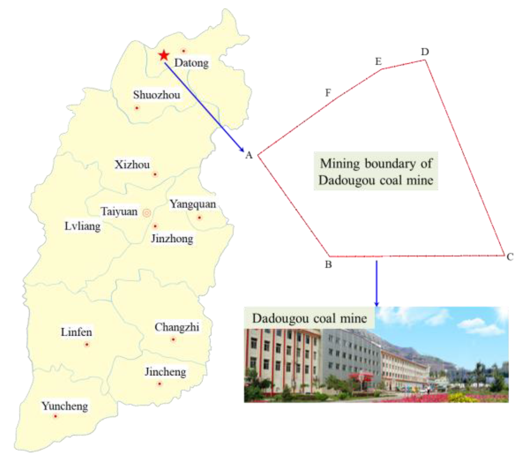
Dadougou coal mine is located in Datong City, Shanxi Province, China (Figure 1), covers a mining area of 12.3 km2, and adopts the NPMM. The minable coal seam is 2# with an average thickness of 2.4 m, a dig angle of 3°, and a burial depth of approximately 400 m. Ten mining panels were arranged in the coal seam extraction area. Based on the geological survey report, the rock lithology of the immediate roof, the main roof, and the floor are silty mudstone, coarse sandstone, and fine sandstone, respectively. The thicknesses are 2.0 m, 13.6 m, and 5.8 m, respectively. The geological stratigraphy column of coal seam 2# is presented in Figure 2. The shearer with the type of MG300/700-AWD, the scraper transfer machine with the type of SGZ800/800, the transfer machine with the type of SZZ830/200, and the crusher with the type of PCM-160 were equipped with mining panels. The mining sequence is panel 5201 → panel 5202 → panel 5203. The entry support adopts a comprehensive scheme of “anchor cable + anchor bolt + anchor net”.

Figure 1.
Location of Dadougou coal mine.
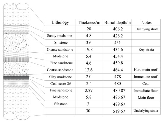
Figure 2.
The geological stratigraphy column of the coal seam 2#.
This study was implemented in mining panel 5202 and its tailgate 5202. The mining panel’s striking and inclination lengths are 1726 m and 180 m, respectively. The mining panel 5202 adopts a fully mechanized mining method. The average mining speed is 3.6 m per day. The entry retained mode is to retain entry along the gob-side by roof cutting. Based on the geological conditions, the average mining height ranges from 2.0 m to 3.0 m. After mining panel 5202 was extracted, the tailgate 5202 was retained as the headgate 5203 of mining panel 5203 for ventilation, material transportation, and pedestrian (Figure 3). The entry was designed as a semi-coal-rock mode with a rectangular shape; the height and the width were 3.6 m and 5.2 m, respectively. Furthermore, the support scheme adopted a combined support mode with anchor bolts, cables, steel belts, and metal meshes. Regarding the mining panel 5202, its recoverable reserves and recoverable period are 1158 million tons and ten months, respectively. One hundred and sixteen hydraulic supports were arranged with a type of ZZ10000/17/35. Its working resistance, setting load, and maximum support height was 7755 kN, 10000 kN, and 3.5 m, respectively.
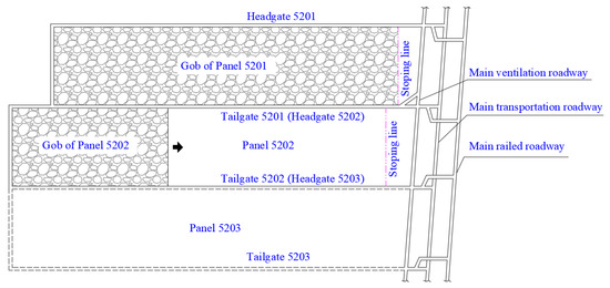
Figure 3.
Layout of 5201 and 5202 panels.
The pre-splitting blasting roof cutting technology adopts the energy-gathered blasting method with two specified directions. The energy-gathered tube with an external diameter, internal diameter, and length of 42 mm, 36.5 mm, and 1.5 m was used for pre-splitting blasting. The tertiary emulsion explosive with a diameter of 35 mm and a length of 30 cm was embedded in an energy-gathered tube based on the charge structure of “4 + 4 + 3 + 3 + 2”. The sealing length with yellow mud was 2.5 m. The roof cutting length was 10 m, the roof cutting angle was 15°, and the spaced distance between the blasting holes was 0.5 m.
2.2. Field Measurement Scheme
The field measurement of the MIGR includes the MIGR of the gob-side entry and the MIGR of the mining panel. To comprehensively study the MIGRs characteristics, a comprehensive measurement program was conducted to obtain sufficient data for assessing the entry convergence, roof fracture development, and advanced abutment pressure and for determining the roof weighting step, hydraulic support working resistance, and hydraulic support end cycle resistance. The detailed monitoring scheme was described as follows.
2.2.1. Entry Convergence
The entry convergence is an important index to assess the surrounding rock stability state [24]. The roof-to-floor convergence and rib-to-rib convergence was field measured by using a laser range finder, tape measure, and lining rope. The monitoring process can be divided into three steps: (1) step 1. Six iron nails were placed in the roof. The position of two iron nails was 1.5 m away from the roof cutting rib, the position of the other two iron nails was 1.5 m away from the virgin coal rib, and the position of the last two iron nails was in the middle section of tailgate 5202. Two iron nails were placed in the roof cutting rib and virgin coal rib; the position was 1.5 m away from the floor. (2) Step 2. The roof-to-floor convergence was assessed using a field test by a laser range finder and tape measure, while the rib-to-rib convergence was assessed using a field test by a tape measure and lining rope. (3) Step 3. The monitoring work was conducted every three days until the mining panel approached the monitoring station. The monitoring data were analyzed for ten days to grasp the evolution law of the entry convergence.
2.2.2. Advanced Abutment Pressure Distribution
The peak value and affection range of the advanced abutment pressure is key to the surrounding rock control. The surrounding rock stress sensor with a type of GYW25 was used for monitoring. The monitoring work can be described as follows: (1) step 1. Two monitoring stations were arranged every 50 m. Each station includes three monitoring points with a length of 6 m, 10 m, and 13 m, respectively. The distance between the monitoring points was 5 m. The monitoring point was placed 1.5 m away from the floor, and the drilled boreholes for installing the surrounding rock stress sensor were perpendicular to the roof cutting rib (Table 1). (2) Step 2. The surrounding rock stress sensor was installed into the borehole with a diameter of 42 mm. After the borehole was drilled, the boreholes were flushed with pressurized water. The stress surface of the surrounding rock stress sensor was kept closed with the surface of the boreholes, and the surrounding rock stress sensor was placed in the specified measuring position. (3) Step 3. The monitoring system used by the infrared ray monitor was used to complete the data collection.

Table 1.
Layout of advanced abutment pressure measuring station.
2.2.3. Mining-Induced Ground Pressure Response
The MIGR is an essential basis for analyzing the roof movement law and has an important guiding significance for optimizing the MIGRs management of the mining panel [25]. The non-coal pillar mining-induced pressure monitoring system with a type of KJ21 was adopted in mining panel 5202. The MIGR includes a hydraulic support working resistance and a hydraulic support end cycle resistance. The monitoring scheme was described as follows: (1) 116 mining intrinsically safe wireless pressure sensors with a type of GPD60W was installed with a number note of 1#, 2#, 3#,……, 117#, and 118# along the inclination direction of mining panel 5202. The mining intrinsically safe wireless pressure sensors with number notes of 1#, 9#, 17#, 25#, and 33# were placed in the range near the non-roof cutting side, mining intrinsically safe wireless pressure sensors with number notes of 86#, 94#, 102#, 110#, and 118# were placed near the roof cutting side, and mining intrinsically safe wireless pressure sensors with a number note of 43#, 51#, 59#, 67#, and 75# were placed in the middle range of mining panel 5201. Mining intrinsically safe wireless pressure sensors of mining panel 5202 were also arranged as mining panel 5201. (2) The monitoring data were collected and transmitted to the terminal system to analyze the roof movement law.
3. Measurement Results and Discussions
3.1. Entry Convergence Analysis
The entry convergence is closely related to the MIGR, such as the lateral and advanced abutment pressure [26]. Considering the MIGRs affection area, the monitoring range in the gob-side entry retained by the roof cutting (GSERC) primary used stage is from −50 m to 150 m (from the mining location of panel 5202 to the monitoring station). The monitoring range in GSERC secondary reused stage is from −50 m to 50 m (from the mining location of panel 5203 to the monitoring station). After applying the monitoring scheme, the entry convergence of the whole period process was obtained. It is noted that the positive value of the monitoring range indicates that the monitoring station is ahead of the mining location of the panel; otherwise, the value of the monitoring range is negative. The development law of the entry convergence is illustrated in Figure 4.
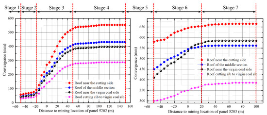
Figure 4.
The development stages of entry convergence in the entire process.
According to the mining stage of panel 5202 and panel 5203, the development stages of the entry convergence can be divided into seven stages; that is, the initial development stage (stage 1), primary slow development stage (stage 2), primary rapid development stage (stage 3), primary stable development stage (stage 4), transition stage from mining panel 5202 to mining panel 5203 (stage 5), secondary rapid development stage (stage 6), and the secondary stable development stage (stage 7). The development features of the seven stages are analyzed as follows:
- The range of stage 1 is greater than 50 m behind the mining location of panel 5202. In stage 1, the surrounding rock is in a stable state under the condition of the combined support, and the entry convergence is mainly the initial deformation under the extraction affection. The maximal value of the initial deformation of stage 1 is 57.6 mm. The range of stage 2 ranges from 20 m to 50 m behind the mining location of panel 5202, and the entry deformation increases slowly in this stage. When panel 5202 moves forward, the mining location of panel 5202 continuously approaches the monitoring station, and the monitoring station is affected by the mining-induced extraction increasingly. The range of stage 2 ranges from −20 m to 50 m away from the monitoring station. The entry convergence develops rapidly because of advanced abutment pressure. The convergence of the middle section, the cutting side, the virgin coal side, and the roof cutting rib to the virgin coal rib rapidly increases to 411 mm, 528 mm, 380 mm, and 274 mm, respectively. The range of stage 4 ranges from 50 m to 150 m ahead of the mining location of panel 5202. In this stage, the entry convergence is stable because of the pre-splitting blasting roof cutting action. Because the action disconnects the stress transfer path between the main roof in the gob and the main roof above the entry, the surrounding rock is little affected by the mining-induced stress field, so the entry convergence decreases, as shown in Figure 4.
- Stage 5 is the transition stage from mining panel 5202 to mining panel 5203. In this stage, the roof collapses and compacts in the gob gradually, and the overlying strata moves stably. The entry convergence changes little. When panel 5203 has retreated, the entry convergence increases rapidly again under the combined affection of the main roof activated movement and advanced abutment pressure of the panel 5203 mining in stage 6. The entry convergence of the middle section, near the cutting side, the virgin coal side, and the roof cutting rib to the virgin coal rib, increased to 558 mm, 654 mm, 572 mm, and 370 mm. After stage 6, the development of the entry convergence tends towards stability.
Overall, the ultimate convergence of tailgate 5202 is caused by the combined action of the mining-induced affection of panel 5202 and panel 5203. In these stages, the entry convergence increases rapidly under the affection of the advanced abutment pressure and the lateral abutment pressure of panel 5202 and the advanced abutment pressure of panel 5203.
3.2. Advanced Abutment Pressure Distribution Analysis
The advanced abutment pressure can provide theoretical guidance for determining the advanced support range of the entry. The measured curve of advanced abutment pressure distribution is shown in Figure 5. As the advancing position of panel 5202 continues to approach the monitoring station, the measured curves of the boreholes with a length of 6 m for monitoring stations 1 and 2 increase slowly, and the change in the advanced abutment pressure is not apparent. The peak value is retained at about 14 MPa and 12 MPa, respectively. As with the boreholes with a length of 6 m, the advanced abutment pressure grows continuously when the distance between the monitoring station and the advancing position ranges from 40 m to 200 m. When the distance between the monitoring station and the advancing position is approximately 30 m, the advanced abutment pressure achieves a peak value of 26.3 MPa and 25.6 MPa, respectively. According to the above analysis, the influence range of the advanced abutment pressure is about 50 m, and the peak influence range is about 35 m ahead of panel 5202.
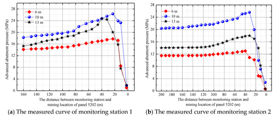
Figure 5.
The advanced abutment pressure distribution.
3.3. Mining-Induced Ground Pressure Response Analysis
3.3.1. Development Law of Hydraulic Support Working Resistance
According to the arrangement of mining intrinsically safe wireless pressure sensors, the maximum value of the hydraulic support working resistance for 1#, 9#, 17#, 25#, and 33# (near the non-roof cutting side) and 86#, 94#, 102#, 110#, and 118# (near the roof cutting side) was statistically analyzed. As shown in Figure 6, the maximum working resistance of the hydraulic support near the non-roof cutting side ranges from 24 MPa to 32 MPa, and the maximum working resistance of most hydraulic supports is greater than 28 MPa. Additionally, the maximum working resistance reaches 34.21 MPa and the average value is 25.7 MPa. Regarding the maximum working resistance of the hydraulic support near the roof cutting side, the value ranges between 18 MPa and 26 MPa, the maximum working resistance of most hydraulic supports is about 26 MPa, the maximum working resistance is 27.4 MPa, and the average value is 23.5 MPa. Compared with the maximum working resistance of the hydraulic support near the non-roof cutting side, the maximum working resistance and changing amplitude near the roof cutting side is gentler. It shows that the roof cutting can effectively cut off the stress transmission, fully release the elastic energy accumulated in the roof, and effectively reduce the loading of the hydraulic support.
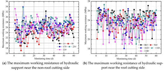
Figure 6.
The measured curve of maximum working resistance of hydraulic support.
3.3.2. Development Law of Hydraulic Support End Cycle Resistance
The measured data within 180 m of the panel 5202 mining were obtained to clarify the development law of the hydraulic support end cycle resistance (Figure 7). The end cycle resistance at the roof cutting side and in the middle of panel 5202 is mostly greater than 30.8 MPa, and the weighting pressure is evident. As for the non-roof cutting side, the end cycle resistance is relatively small with a value of less than 26 MPa. The end cycle resistance shows that the MIGR of panel 5202 is asymmetric. That is, the ground pressure response near the roof cutting side is relatively weak, while the ground pressure response near the non-roof cutting side is severe.
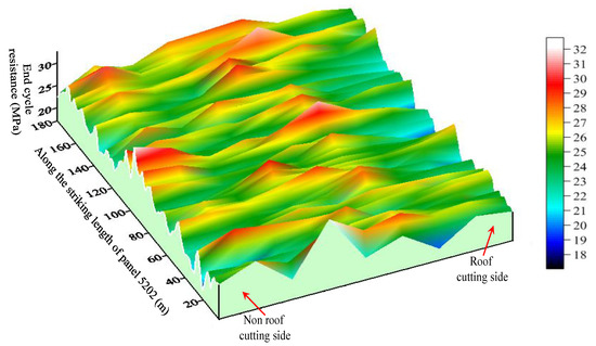
Figure 7.
End cycle resistance development of panel 5202 within the striking length of 180 m.
Based on the measured result of the working resistance and end cycle resistance of the hydraulic support, combined with the analysis of the roof weighting step distance, the development law of the MIGR can be summarized as follows:
- (1)
- As illustrated in Table 2, the average value of the periodic weighting length in the section of panel 5202 near the non-roof cutting side, in the middle section of panel 5202, and the section of panel 5202 near the roof cutting side is 32.1 m, 34.2 m, and 29.05 m, respectively. Moreover, the dynamic loading coefficients are 1.17, 1.33, and 1.07, respectively. The periodic weighting length and the dynamic loading coefficient can be characterized by the section of panel 5202 near the non-roof cutting side > the middle section of panel 5202 > the section of panel 5202 near the roof cutting side.
Table 2. Result analysis of mining-induced ground response.
- (2)
- Regarding the roof weighting magnitude, it is most significant in the middle section of panel 5202, followed by the section of panel 5202 near the non-roof cutting side, and the smallest in the section of panel 5202 near the roof cutting side. It can be concluded that the MIGR has significant asymmetric characteristics. That is, the MIGR in the section of panel 5202 is significantly smaller than that of the middle section and section near the non-roof cutting side. The reason is that the roof cutting action has changed the roof’s structure. In detail, the key block of the main roof has been cut off into two sections; one section collapses in the gob and the other remains above the entry. Hence, the stress transmission path is cut off, so the ground response near the roof cutting side is relatively small.
As shown in Figure 8, the distribution of the end cycle resistance along the inclination length presents the characteristic of “large in the middle section and small at both ends” with the shape of a parabolic curve. Unlike the panel with traditional longwall mining, the end cycle resistance distribution is not symmetrical in the middle section of the panel, but it is asymmetrical at both ends. According to the measured data, the end cycle resistance is in a lower state with the value of 24.98 MPa~26.55 MPa near the roof cutting side. When the inclination length ranges from 65 m to 130 m, the end cycle resistance is more remarkable than 32.93 MPa with a maximum value of 37.22 MPa.
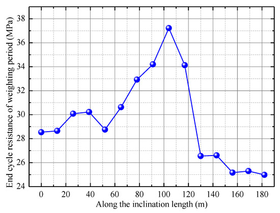
Figure 8.
End cycle resistance development along the inclination length.
4. Numerical Simulation Analysis
4.1. Numerical Simulation Model
Due to the limitations of the field measurement for the MIGR, the numerical simulation method is used to clarify the development law of the MIGR in the mining process of panels 5202 and panel 5203. The numerical simulation model covers a size of 470 m × 600 m × 160 m (Figure 9). The mesh along the x, y, and z directions and the element numbers of the numerical simulation model are 4,586,400 and 4,689,500, respectively. The boundary of the numerical simulation model which can be described as the top is a free boundary, and other boundaries were constrained. A vertical compressive stress of 10 MPa was imposed on the top surface based on the burial depth of 450 m. Vertical and horizontal model boundaries are subjected to horizontal boundary stresses that simulate major and minor in situ stresses, and the lateral pressure coefficient was set as 1.25.
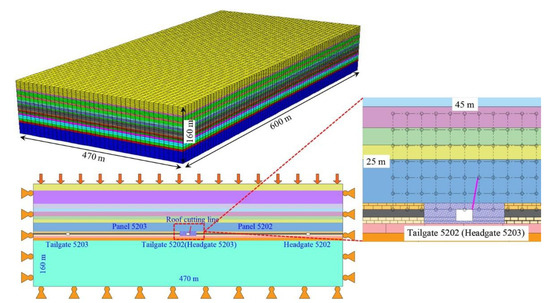
Figure 9.
The numerical simulation model and monitoring points arrangement.
The numerical simulation process can be presented as follows: the excavation of tailgate 5202 and headgate 5202 → the roof cutting of tailgate 5202 → panel 5202 advances → tailgate 5203 excavation → panel 5203 advances. The roof cutting height and angle are 9 m and 15°, respectively. A total of six monitoring lines were placed vertically above the roof. Furthermore, to clarify the influence law of roof cutting on the surrounding rock mass state of the roof above the GSERC, the stress and displacement of the overlying roof within 25 m above the GSERC are monitored. The monitoring points are presented in Figure 9.
The Mohr–Coulomb failure criterion was selected for the numerical simulation. The reasonable determination of the physical and mechanical parameters is the base of acquiring reliable numerical results. Combined with the existing reference [27,28,29], the bulk modulus, shear modulus, tensile strength, and cohesion are 0.25 times the measured results. The physical and mechanical parameters of the coal and rock mass are determined based on the laboratory test results, as shown in Table 3. The null unit is used to simulate panel mining and roof cutting. The panel mining adopts stepped excavation with a step of 10 m.
Table 3.
Rock mass mechanical parameters for the numerical model.
4.2. Numerical Simulation Result Analysis
4.2.1. Influence of Roof Cutting on Displacement Development
The mining-induced vertical stress development above 15 m of the overlying roof is obtained based on the numerical simulation results. The vertical stress distribution range is divided into the section near the roof cutting side, the middle section, and the section near the non-roof cutting side. As panel 5202 continually advances, the vertical stress constantly changes. As presented in Figure 10, the vertical stress distribution still presents asymmetric characteristics. That is, the value of vertical stress in the section near the roof cutting side is less than that near the non-roof cutting side. The vertical stress ranges from −8.6 MPa to −27.2 MPa in the section near the roof cutting side, while the vertical stress ranges from −10.3 MPa to 43.6 MPa. Regarding the variation amplitude, the vertical stress distribution in the section near the roof cutting side is gentler than near the non-roof cutting side. The numerical simulation result of the vertical stress development law is consistent with the field measurement results of the end cycle resistance development law.
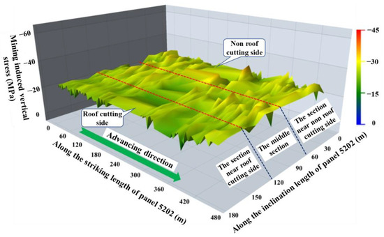
Figure 10.
Mining-induced vertical stress development.
Roof cutting has a significant influence on the displacement [30,31]. For analyzing the development law of stress and displacement near the roof cutting range, vertical stress, vertical displacement, horizontal stress, and horizontal displacement were expounded. The vertical and horizontal displacement was within 25 m above the entry roof, as shown in Figure 11. As for the horizontal distance of the roof, it should be noted that the positive value indicates that the range belongs to the gob of panel 5202. Otherwise, the negative value indicates that the range belongs to the virgin coal of panel 5203. It can be seen that within the scope of −22.5~22.5 m, the vertical displacement of the roof within 0~10 m above the entry presents a changing trend of a slow increase in the initial stage → rapid increase in the middle stage → decline in the later stage, with prominent zoning characteristics.
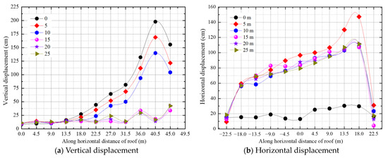
Figure 11.
Development of vertical displacement and horizontal displacement under the influence of roof cutting.
(1) According to the vertical displacement development (Figure 11a), it can be divided into three divisions: slowly increasing division (along the horizontal distance of -22.5~0 m), rapid increasing division (along the horizontal distance of 0~18 m), and decreasing division (along the horizontal distance of roadway 18~22.5 m). The vertical displacement in the slowly increasing division ranges from 8.32 cm to 27.14 cm, and the vertical displacement gradually increases as it approaches the entry. A rapid increase characterizes the vertical displacement development in the rapidly growing division. The vertical displacement rapidly rises from the minimum value of 13.92 cm to the maximum value of 197.9 cm. The vertical displacement in the decreasing division decreased from the maximum value to 13.83 cm.
(2) From the view of the horizontal direction, with the central axis of x = 22.5 m as the symmetry axis, the vertical displacement has a noticeable “asymmetric development” feature; that is, the vertical displacement of the roof near the roof cutting side is significantly greater than that near the non-roof cutting side. Along the vertical direction, the vertical displacement within the range above the roof has the characteristics of “polarization”. That is, the vertical displacement of the roof within the range of 0~15 m above the entry increases slowly at the non-roof cutting side but it increases rapidly at the roof cutting side. The maximum vertical displacement of the roof at the roof cutting side is 7.3 times the maximum vertical displacement of the roof at the non-roof cutting side, which indicates that the roof cutting plays a vital role in the significant subsidence of the roof above the entry. Regarding the roof within 15~25 m above the entry, the vertical displacement shows a slowly increasing trend. The maximum vertical displacement of the roof at the roof cutting side is 2.56 times that at the non-roof cutting side. It shows that the full influence range of the roof cutting is within the range of 0~15 m above the entry, and the influence on the roof within the range of 15~25 m above the entry is little. The effect of roof cutting on the lower level of the main roof is significant, while the impact on the upper level of the main roof is weak.
(3) From the view of the horizontal direction, the fluctuation range of horizontal displacement development is more prominent as it is closer to the roof cutting side, and the horizontal displacement increases accordingly. The maximum horizontal displacement value is 59.45 cm at the horizontal distance of −18 m and 147.2 cm at the horizontal distance of 18 m. It can be seen that the horizontal displacement at the roof cutting side is generally more prominent than that at the non-roof cutting side, and the horizontal displacement also has a significant “asymmetric development” feature.
(4) From the view of the vertical direction, the horizontal displacement of the roof at 0 m above the entry is always at a low value, and the maximum value of the horizontal displacement is 18.39 cm, which is much smaller than the horizontal displacement at 5~25 m above the entry. It is mainly because the roof within this range is the direct roof. It is the horizontal displacement of the crushed stone after it is caved. However, the horizontal displacement still has the characteristic of “asymmetric development”. The horizontal displacement at the roof cutting side is more significant than at the non-roof cutting side.
4.2.2. Influence of Roof Cutting on Stress Development
The vertical stress is along the horizontal distance of −22.5~22.5 m above the roof, as shown in Figure 12a. It can be seen that the vertical stress shows a gradually decreasing trend.
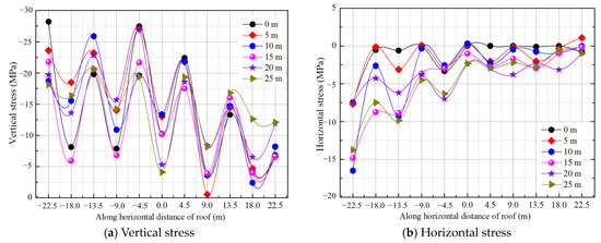
Figure 12.
Development of vertical stress and horizontal stress under the influence of roof cutting.
(1) From the view of the horizontal direction, with the central axis of the roadway as the symmetry axis, the vertical stress at the roof cutting side is generally significant, and the maximum and minimum values are −28.2 MPa and −6.79 MPa, respectively. The vertical stress at the roof cutting side is significantly smaller than the non-roof cutting side. The maximum and minimum values are −22.4 MPa and −0.5259 MPa, respectively. It can be seen that the roof cutting releases the rock mass stress at the roof cutting side, so the vertical stress also decreases correspondingly. Roof cutting reduces the stress transmission and plays an essential role in pressure relief.
(2) From the view of the vertical direction, the maximum vertical stress of the roof at 0 m, 5 m, 10 m, 15 m, 20 m, and 25 m above the entry is −13.3 MPa, −14.43 Mpa, −14.72 Mpa, −16 Mpa, −14.5 Mpa, and −16.79 MPa, respectively, along the horizontal distance of 0~22.5 m (i.e., the roof above roof cutting side). The minimum vertical stress is −3.79 MPa, −0.5259 MPa, −3.611 MPa, −3.893 MPa, −8.394 MPa, and −8.16 MPa, respectively. It can be seen that the stress release area caused by roof cutting is mainly concentrated in the lower level of the main roof, while the stress release effect on the upper level of the main roof is limited.
The horizontal stress is along the horizontal distance of −22.5~22.5 m above the roof, as shown in Figure 12b. The results can be described as follows:
- (1)
- From the view of the horizontal direction, with the central axis of the roadway as the symmetry axis, the horizontal stress along the horizontal distance of −22.5~0 m is generally more significant than the horizontal stress along the horizontal distance of 0~22.5 m. In particular, the horizontal stress with a horizontal distance of −22.5~0 m is mainly distributed at −3.6~0.5 MPa, while the horizontal distance of 0~22.5 m is primarily distributed at −16.8~0 MPa. It can be seen that the horizontal stress also presents the characteristics of “asymmetric development”.
- (2)
- From the view of the vertical direction, the fluctuation in the horizontal stress along the horizontal distance of −22.5~0 m is more significant than that along the horizontal distance of 0~22.5 m. The fluctuation in the horizontal stress at 10~25 m above the entry is substantial, but the horizontal stress at the roof cutting side is relatively small.
5. Mining-Induced Ground Response Division
After analyzing the field measurement and numerical simulation results, it is indicated that the MIGR presents a prominent “asymmetric development” feature. Specifically, the mining-induced ground response, including the end cycle resistance and working resistance, presents a feature of asymmetric development, and entry convergence also has a characteristic of asymmetric development. Hence, the mining-induced ground response along the inclination length can be divided into five divisions of I, II, III, IV, and V, as shown in Figure 13. The feature of each division is described as follows.
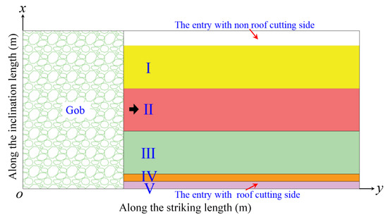
Figure 13.
Zone division of mining-induced ground response.
Division I: this division is near the entry with the non-roof cutting side. The ground response is relatively weak within a specific range along the inclination length of tens of meters. The working and end cycle resistance of the hydraulic support do not rise significantly in the incoming pressure period. The stress distribution is relatively gentle, and the low-stress range is slightly large than that of the conventional mining mode.
Division II: this division is located in the middle section of the panel. The mining-induced ground response appears obvious, and the vertical stress is more significant than in other regions. The working and end cycle resistance of the hydraulic support is more significant than that of other regions. The dynamic loading coefficient is high because of the apparent incoming ground pressure. Therefore, the monitoring works should be strengthened according to the state of the hydraulic supports, to prevent the hydraulic support from damaging and the roof from collapsing.
Division III: this division is near the entry with the roof cutting side. The mining-induced ground pressure within a specific range from the entry with the roof cutting side is weak, and the end cycle resistance and working resistance of the hydraulic support also do not rise significantly when the panel is approached. The front region of the panel is affected by advanced abutment pressure, but its value is lower than that of divisions I and II. Based on comprehensive analysis, the mining-induced ground response is the smallest. Hence, regarding the mining-induced ground pressure degree, the comprehensive rank is division II > division I > division III.
Division IV: this division is the entry near the roof cutting side, mainly the gangue rib, and the roof near the roof cutting side. The entry convergence including roof-to-floor convergence, and gangue rib extrusion deformation, is more significant than in other regions. Hence, the asymmetric arrangement of the supporting structures, such as anchor bolts and cables, should be strengthened to increase the supporting density.
Division V: this is the entry near the virgin coal side, mainly the virgin coal rib and the roof near the virgin coal side. Compared with division IV, the roof and virgin coal rib deformation are relatively small. However, the supporting intensity should be improved when the adjacent panel is mined.
6. Discussion
With the demand for coal reserves, the non-coal pillar mining method has been widely applied to eliminate the coal pillar between mining panels. After reviewing the literatures, the mining-induced ground response regarding the entire period, including the first mining panel and the adjacent mining panel, still suffers from some limitations; accordingly, there is no targeted management reply and approach for the mining-induced ground response.
Based on the field investigation, the mining-induced ground response of the mining panel and its corresponding entry was studied by a field measurement, numerical simulation, and theoretical analysis. It is concluded that roof cutting action is a key factor. The mining-induced ground response of entry presents the asymmetrical feature; that is, the convergence near the roof cutting side is greater than that near the non-roof cutting side. The mining-induced ground response of the mining panel also represents the asymmetrical feature; that is, the ground pressure near the roof cutting side is less than that near the non-roof cutting side. The results can provide a reliable reply for ground response management and safety mining.
It needs to be pointed out that the study was based on a specific coal mine; the detailed, changeable response depends on actual geological and mining conditions. More studies are needed to be promoted according to different conditions. However, the results presented in the study can provide reply schemes for other coal mines.
7. Conclusions
This study aimed to obtain the characteristics of the mining-induced ground response of the non-coal pillar mining panel and adopted a comprehensive method of an in situ measurement, numerical simulation, and theoretical analysis, to provide targeted guidance for the control reply of the mining-induced ground response. The results acquired are as follows:
- Entry convergence, the hydraulic support working resistance, the hydraulic support end cycle resistance, and the main roof periodic weighting distance present the characteristics of “asymmetric development”. The mining-induced ground pressure along the inclination length of the panel shows the asymmetric development. The entry convergence near the roof cutting side is more significant than near the non-roof cutting side.
- The roof cutting action released the stress of the surrounding rock near the roof cutting side. The roof cutting which influences the range is within 10 m above the roof, and the pressure relief effect of the lower level for the main roof is better than the upper level for the main roof. The distribution of the stress and displacement fields is asymmetric due to the roof cutting action.
- The primary rapid development stage and the second rapid development stage are vital stages that need to be controlled. The mining-induced response division can be divided into five divisions, and divisions II and IV should be paid more attention.
Author Contributions
Conceptualization, H.Z. and H.W.; methodology, H.Z.; software, H.Z.; validation, H.Z., formal analysis, H.Z.; investigation, H.Z.; resources, H.Z.; data curation, H.Z.; writing—original draft preparation, H.Z.; writing—review and editing, H.Z.; visualization, H.Z.; supervision, H.W; project administration, H.Z.; funding acquisition, H.Z. All authors have read and agreed to the published version of the manuscript.
Funding
This research was funded by National Natural Science Foundation of China (51974317), Open Fund of State Key Laboratory of Water Resource Protection and Utilization in Coal Mining (WPUKFJJ2019-19).
Institutional Review Board Statement
Not applicable.
Informed Consent Statement
Not applicable.
Data Availability Statement
The data used to support the findings of this research are included within the paper.
Acknowledgments
The authors are grateful to China Jinneng Holding Group for helping with the collected data in this study. The authors also thank engineers and workers for their constructive suggestions and valuable assistance in the process of the research program.
Conflicts of Interest
The authors declare that there are no conflicts of interest.
References
- He, F.L.; Zhu, R.J.; Zhu, H.Z. Numerical insights into stress redistribution in protected seam mining with coal pillars and an application to methane control. Acta Geodyn Geomater 2019, 2, 169–182. [Google Scholar] [CrossRef]
- Yang, W.; Lin, B.Q.; Yan, Q.; Zhai, C. Stress redistribution of longwall mining stope and gas control of multi-layer coal seams. Int. J. Rock Mech. Min. Sci. 2014, 72, 8–15. [Google Scholar] [CrossRef]
- Yu, B.; Zhang, Z.Y.; Kuang, T.J.; Liu, J.R. Stress changes and deformation monitoring of longwall coal pillars located in weak ground. Rock Mech. Rock Eng. 2016, 49, 3293–3305. [Google Scholar] [CrossRef]
- Zhang, X.Y.; He, M.C.; Yang, J.; Wang, E.Y.; Zhang, J.B.; Sun, Y. An innovative non-pillar coal-mining technology with automatically formed entry: A case study. Engineering 2020, 6, 1315–1329. [Google Scholar] [CrossRef]
- Wang, Y.J.; He, M.C.; Yang, J.; Wang, Q.; Liu, J.N.; Tian, X.C.; Gao, Y.B. Case study on pressure-relief mining technology without advance tunneling and coal pillars in longwall mining. Tunn. Undergr. Space Technol. 2020, 97, 103236. [Google Scholar] [CrossRef]
- Yang, J.; He, M.C.; Cao, C. Design principles and key technologies of gob side entry retaining by roof pre-fracturing. Tunn. Undergr. Space Technol. 2019, 90, 309–318. [Google Scholar] [CrossRef]
- Tao, Z.G.; Song, Z.G.; He, M.C.; Meng, Z.G.; Pang, S.H. Principles of the roof cut short-arm beam mining method (110 method) and its mining-induced stress distribution. Int. J. Min. Sci. Technol. 2018, 28, 391–396. [Google Scholar] [CrossRef]
- Wang, Q.; He, M.C.; Li, S.C.; Jiang, Z.H.; Wang, Y.; Qin, Q.; Jiang, B. Comparative study of model tests on automatically formed roadway and gob-side entry driving in deep coal mines. Int. J. Min. Sci. Technol. 2021, 31, 591–601. [Google Scholar] [CrossRef]
- Zhang, X.Y.; Hu, J.Z.; Xue, H.J.; Mao, W.B.; Gao, Y.B.; Yang, J.; He, M.C. Innovative approach based on roof cutting by energy-gathering blasting for protecting roadways in coal mines. Tunn. Undergr. Space Technol. 2020, 99, 103387. [Google Scholar] [CrossRef]
- Gao, Y.B.; Wang, Y.J.; Yang, J.; Zhang, X.Y.; He, M.C. Meso- and macro effects of roof split blasting on the stability of gateroad surroundings in an innovative non pillar mining method. Tunn. Undergr. Space Technol. 2019, 90, 99–118. [Google Scholar] [CrossRef]
- He, M.C.; Song, Z.Q.; Wang, A.; Yang, H.H.; Qi, H.G.; Guo, Z.B. Theory of longwall mining by using roof cuting shortwall team and 110 method-the third mining science and technology reform. Coal Sci. Technol. Mag. 2017, 1, 1–9+13. [Google Scholar]
- Qian, M.G.; Zhang, D.L.; Li, L.J.; Kang, L.X.; Xu, J.L. “S-R” stability for voussoir beam and its application. J. Min. Saf. Eng. 1994, 3, 6–11. [Google Scholar]
- Song, Z.Q.; Jiang, Y.J.; Liu, J.K. Theory and model of “practical method of mine pressure control”. Coal Sci. Technol. Mag. 2017, 2, 1–10. [Google Scholar]
- Miao, X.X.; Qian, M.G. Advance in the key strata theory of mining rockmass. J. China Univ. Min. Technol. 2000, 29, 25–29. [Google Scholar]
- Shi, H.; Jiang, F.X. Structural theories of overlying strata in longwall faces and their new development. J. Shandong Univ. Sci. Technol. 2005, 24, 22–25. [Google Scholar]
- Han, X.; Zhang, S.Y.; Wang, J.; Ma, X.G.; Yu, G.Y. Law behind surrounding rock deformation in retaining roadway based on theory of cut-wall short-wall beam. J. Heilongjiang Univ. Sci. Technol. 2019, 2, 138–142. [Google Scholar]
- Hua, X.Z.; Liu, X.; Huang, Z.G.; Yang, P.; Ma, Y. Stability mechanism of non-pillar gob-side entry retaining by roof cutting under the coupled static-dynamic loading. J. China Coal Soc. 2020, 45, 3696–3708. [Google Scholar]
- Gao, H.N.; Gao, Y.B.; Wang, J.; Fu, Q.; Qiao, B.W.; Wei, X.J.; Zhang, X.Y. Study on bidirectional blasting technology for composite sandstone roof in gob-side entry-retaining mining method. Appl. Sci. 2021, 11, 7524. [Google Scholar] [CrossRef]
- Wang, Q.; Wang, Y.; He, M.C.; Li, S.C.; Zhang, Z.H.; Jiang, B.; Xu, S.; Wei, H.Y. Experimental study on the mechanism of pressure releasing control in deep coal mine roadways located in faulted zone. Geomech. Geophys. Geo-Energy Geo-resour. 2022, 8, 50. [Google Scholar] [CrossRef]
- Zhen, E.Z.; Wang, Y.J.; Yang, J.; He, M.C. Comparison of the macroscopical stress field distribution characteristics between a novel non-pillar mining technique and two other current methods. Adv. Mech. Eng. 2019, 11, 1–15. [Google Scholar] [CrossRef]
- Wang, Y.J.; He, M.C.; Zhang, K.X.; Yang, J.; Zhen, E.Z.; Zhu, Z.; Gao, Y.B.; Ma, Z.M. Strata behavior characteristics and control countermeasures for the gateroad surroundings in innovative non-pillar mining method with gateroad formed automatically. J. Min. Saf. Eng. 2018, 35, 677–685. [Google Scholar]
- Chi, B.S.; Wang, J.W.; Liu, H.; Ming, C.; Li, K. Study on law of full—Period mine pressure behavior of entry retaining method of self—Contained entry without coal pillar. Coal Sci. Technol. 2020, 48, 123–129. [Google Scholar]
- Wang, Y.J.; He, M.C.; Yang, J.; Fu, Q.; Gao, Y.B. The structure characteristics and deformation of “short cantilever beam” using a non-pillar mining method with gob-side entry formed automatically. J. China Univ. Min. Technol. 2019, 48, 718–726. [Google Scholar]
- Zhang, Y.; Zhu, H.Z.; Zhu, J.B.; Ou, Z.B.; Shen, T.; Sun, J.J.; Feng, A.N. Experimental study on separation of lumpish coal and gangue using X-ray. Energy Sources Part A Recovery Util. Environ. Eff. 2022, 1976325. [Google Scholar] [CrossRef]
- Zhao, M.Y.; Huang, Q.X.; Huang, K.J.; Xue, W.F.; ANDJi, R.J. Pressure behavior of gob-side entry retaining with roof cutting and nonpillar mining. J. Xi’an Univ. Sci. Technol. 2019, 39, 597–602. [Google Scholar]
- Ma, X.G.; He, M.C.; Wang, J.; Gao, Y.B.; Zhu, D.Y.; Liu, Y.X. Mine strata pressure characteristics and mechanisms in gob-side entry retention by roof cutting under medium-thick coal seam and compound roof conditions. Energies 2018, 11, 2539. [Google Scholar] [CrossRef]
- Sun, X.M.; Li, G.; Zhao, J.Q.; He, M.C.; Song, P.; Miao, C.Y. Numerical investigation of gob-side entry retaining through precut overhanging hard roof to control rockburst. Adv. Civ. Eng. 2018, 2018, 8685427. [Google Scholar] [CrossRef]
- Wang, Y.X.; Ma, D.; Qi, Q.X. Study on determining of the mechanical parameters of rock mass used in numerical simulation. J. China Coal Soc. 2003, 28, 594–597. [Google Scholar]
- Chen, X.X.; Xie, W.B.; Jing, S.G.; Wei, W.Z. Determination of mechanics parameters of mining induced rock mass for numerical simulation. J. Min. Saf. Eng. 2006, 23, 341–345. [Google Scholar]
- Khan, N.M.; Ahmad, M.; Cao, K.; Ali, I.; Liu, W.; Rehman, H.; Hussain, S.; Rehman, F.U.; Ahmed, T. Developing a new bursting liability index based on energy evolution for coal under different loading rates. Sustainability 2022, 14, 1572. [Google Scholar] [CrossRef]
- Chen, J.H.; Tao, K.M.; Zeng, B.Q.; Liu, L.; Zhao, H.B.; Zhang, J.W.; Li, D.Q. Experimental and numerical investigation of the tensile performance and failure process of a modified Portland cement. Int. J. Concr. Struct. Mater. 2022, 16, 1–14. [Google Scholar] [CrossRef]


Disclaimer/Publisher’s Note: The statements, opinions and data contained in all publications are solely those of the individual author(s) and contributor(s) and not of MDPI and/or the editor(s). MDPI and/or the editor(s) disclaim responsibility for any injury to people or property resulting from any ideas, methods, instructions or products referred to in the content. |
© 2023 by the authors. Licensee MDPI, Basel, Switzerland. This article is an open access article distributed under the terms and conditions of the Creative Commons Attribution (CC BY) license (https://creativecommons.org/licenses/by/4.0/).