Article

Research into the Mechanism and Application of Liquid CO2 Phase-Transition Fracturing in a Coal Seam to Enhance Permeability

1
School of Mine and Coal, Inner Mongolia University of Science and Technology, Baotou 014010, China
2
State Key Laboratory of Gas Disaster Monitoring and Emergency Technology, Chongqing 400037, China
3
China Coal Technology and Engineering Group Chongqing Research Institute, Chongqing 400037, China
Sustainability 2023, 15(4), 3308; https://doi.org/10.3390/su15043308
Submission received: 21 November 2022 / Revised: 23 January 2023 / Accepted: 8 February 2023 / Published: 10 February 2023
(This article belongs to the Special Issue Green and Scientific Design of Deep Underground Engineering)

Abstract

:
The geological structures of the coal fields in China are complex. With a continuous increase in the mining depth, the coal seams show the characteristics of high gas and low permeability, and the disaster potential for a coal and gas outburst intensifies in the process of coal mining. Gas drainage is one of the primary measures used to prevent and control gas disasters. Effectively improving the permeability of a coal seam requires urgent attention. Currently, the method of loose blasting is used in engineering to enhance the permeability of coal seams. However, the technology of loose blasting easily leads to the poor development of coal fractures or the severe crushing of coal, which will affect the gas drainage. Thus, this paper studied the technology of liquid CO2 phase-transition fracturing in a coal seam. COMSOL was used to determine the influence radius of the liquid carbon-dioxide phase-transition cracking, which was 13.4 m, and to design the scheme of the borehole. The field test was carried out in the 81,506th working face of the Baode Coal Mine. From the onsite-monitoring data, the results showed that the drainage effect increased by 293.9%, the gas-drainage concentration increased by 242.4%, the permeability coefficient of the coal seam increased by 3–7.75 times, and the permeability enhancement effect was good.

1. Introduction

For a long time, gas has seriously restricted the safe production of coal-mine enterprises [1,2,3]. With an increase in the mining depth, the permeability of the coal seam becomes lower and lower. Enhancing the permeability of a coal seam is a prerequisite for gas extraction and the safe production of coal mines. At present, hydraulic-fracturing technology is widely used in gas extraction [4,5,6]. However, the effect of the coal-seam-permeability improvement is poor for the downward layer through the borehole. The influence of the different thicknesses and hardness of a coal seam on the effect of permeability enhancement has been studied less. An understanding of the coal-breaking mechanism of hydraulic punching and the mechanism of increasing permeability and pressure relief are lacking. The process and technical parameters of hydraulic punching need to be further studied. The common punching process can easily cause problems such as holding holes, plugging holes, sticking, and running water. In particular, the coal–water mixture flushed from the upward hole tends to accumulate at the upper opening of the casing, which directly affects the drilling and flushing process [7,8,9]. Therefore, there is an urgent need to find a penetration-enhancement method with a good penetration effect and high safety. This paper analyzes and evaluates the technology of the liquid CO2 phase-transition fracturing in a coal seam to enhance permeability.
The liquid-carbon-dioxide phase-transition cracking device uses a heating tube to heat the liquid carbon dioxide in the fluid-storage tube, changing it from a liquid state to a gas state, and increasing the pressure sharply [10,11,12]. Then the high-pressure gas smashes the constant-pressure energy sheet and generates stress waves that propagate. The generated gas passes through the release channel of the exhaust pipe and reaches the coal mass in a short time to form an explosive airflow. Stress waves and high-energy gas not only generate new cracks in the coal mass but can also make the original cracks expand [13,14,15].
The liquid-carbon-dioxide phase-change fracturing technology was first proposed by the Cardox International, UK, called the Cardox Tube System [16]. Singh introduced the main structure and application method of the device and pointed out that the device can be used for large-scale mining and excavation of a quarry. Due to its high safety profile, the device can be used for underwater operation and for fast and safe blasting near reservoirs and dams [17]. In Turkey, coal mines use the Cardox device in the working face to split the coal mass by the high-pressure carbon dioxide gas generated instantly, thus, improving the lump coal rate [18]. Lekontsev compared several explosion-proof rock fracture technologies and suggested that the Cardox device does not belong to the scope of explosion but only to a high-pressure gas generator [19]. Therefore, it is not limited by the control of explosives, which have a limited scope of use. With its safety and stability, the liquid-carbon-dioxide phase-change cracking can be applied to the cleaning of large storage tank walls. As carbon dioxide gas is an inert gas, the device can be applied to the treatment of flammable and combustible materials. Lisienko studied the carbon dioxide cannon by simulating coal blasting on the ground and stated that the liquid-carbon-dioxide blasting was a slow and expansive diffusing and shearing process, which caused the released carbon dioxide gas to cut along the natural cracks of coal or explosives and was most suitable for the blasting of porous brittle materials [20]. Xiang Cheng tested carbon-dioxide blasting in the working face of Luling Coal Mine. After blasting, the effect of the coal briquetting was good, the amount of coal thrown was large, and the ratio of fine coal was significantly reduced [21].
The phase-change fracturing technology of liquid carbon dioxide is a new technology for the coal industry, which uses the huge energy released by liquid carbon dioxide in the process of the liquid-gas two-phase transformation in a confined space to act on the original fractures, and the fracturing effect of the high-energy gas expands the original fractures [22]. At the same time, the impact force generated during fracturing breaks the hole in the wall, creating new cracks, which increases the crack development of materials, improves the permeability of materials, and even breaks materials.

1.1. Effect of the Stress Wave on the Coal Mass

When high-pressure carbon dioxide gas is ejected from the fluid-storage pipe, it is accompanied by the generation of stress waves. When the coal mass is regarded as an ideal elastomer, the motion equation of the coal-rock particle when the elastic wave propagates is as follows:
( λ + G ) θ x i + G 2 u i = ρ 2 u i t 2 i   =   1 ,   2 ,   3
where ui is the displacement of the particle in the coordinate direction; θ = εij = uij is the volumetric strain; ∇2 is the Laplace operator; λ, G is the lame elastic constant; ρ is the density of coal-rock mass; and t is time.

1.2. High-Pressure-Gas-Gathering Cutting by the Phase Change of Liquid Carbon Dioxide

The unique design of the end of the release pipe in the liquid-carbon-dioxide phase-transition equipment can solve the problem of the blasting energy dispersion and dilution. The exhaust hole of the release pipe allows the gas to be discharged in a fixed direction, so that the energy is gathered and fractures the coal mass. When the high-pressure liquid-carbon-dioxide gas impacts the coal in the form of jet, the high-pressure gas radiates from the center of the jet.
The impact of the high-pressure carbon dioxide gas that fractures the coal mass is divided into the following categories: the cavitation damage, the impact cutting effect of the high-pressure gas, the dynamic pressure effect of high-pressure gas, and the gas-wedge effect formed by high pressure gas. Under the impact of high-pressure carbon dioxide gas, the internal-stress distribution of the coal mass is similar to the half-space elastomer under the concentrated load. When the compressive stress generated by the impact of high-pressure gas reaches or exceeds the compressive strength of the coal body, the original coal body is damaged, and cracks are formed in the coal body. When the compressive stress generated by the impact of high-pressure gas exceeds the compressive strength of the coal mass, the original coal mass is damaged, and cracks are formed. The high-pressure gas entering the cracks causes the cracks to develop and expand rapidly, resulting in the fracture of the coal seam.

1.3. Coal Seams Fractured by the Liquid Carbon Dioxide Phase-Change Expansion Force

The liquid carbon dioxide in the liquid-storage pipe gradually changes into gaseous carbon dioxide after heating, the volume expands continuously, and the pressure of the carbon dioxide gas increases continuously [23,24,25]. When the carbon dioxide gas breaks through the constant pressure valve and is ejected through the release pipe, the carbon dioxide gas still expands and increases, generating expansion work [26,27,28]. The high-pressure carbon dioxide gas exerts pressure on the wall of the fracturing boreholes, forcing new fractures to form in the coal seam. Otherwise, the high-pressure carbon dioxide gas enters the coal seam and expands the original fractures in the coal seam.

2. Methods

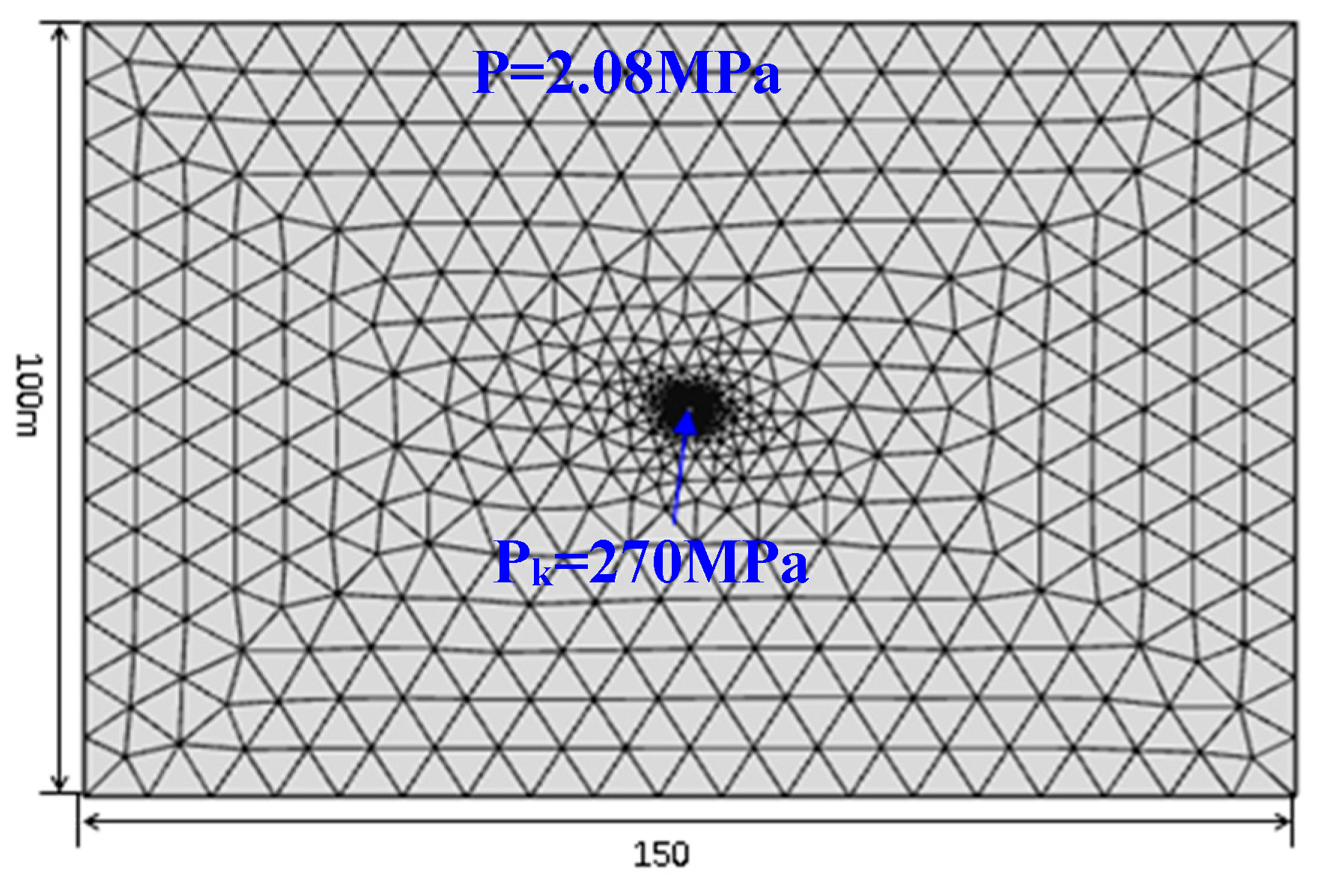
2.1. Numerical Model

To study the influence radius of the liquid-carbon-dioxide phase-transition cracking, taking the #8 coal seam of Baode Coal Mine China as the engineering background, COMSOL was used for analysis. In the numerical calculations, a gas pressure of 270 MPa was applied to simulate the cracking gas pressure generated during the phase transition of liquid carbon dioxide. The parameters of the coal mass are shown in Table 1.
The model was constructed with the 81,506th working face of Baode Coal Mine as the engineering background, and the model is shown in Figure 1. The size of the model was 150 m × 100 m, and the fracturing boreholes were in the middle of the calculation model. To facilitate the calculation, the mesh size was differentiated [29,30,31]. The mesh size near the fracturing boreholes was small and dense, and the mesh size away from the fracturing boreholes was large and sparse [32,33,34]. The boundary of the model was fixed, and the diameter of the borehole was 113 mm. The boundary condition of the orifice was Darcy’s law, and the pressure used to simulate the fracturing gas pressure generated during the phase change of liquid CO2 was 270 MPa. The upper boundary of the model was subject to a uniformly distributed, original rock stress of 2.08 MPa.

2.2. Theoretical Calculation

According to the theory of elastic mechanics and fracture mechanics [35], the fracturing radius of the coal mass of the gas phase transition can be calculated using the following formula:
r c = r h × ( P max K t S t ) 1 α
where rc is the fracturing radius of the coal mass of the gas phase transition in m; rh is the radius of the borehole in mm; Pmax is the pressure peak of the gas phase transition in MPa; Kt is the improving coefficient of tensile strength with dynamic load; St is the tensile strength of coal mass with static load in MPa; and α is the attenuation index.
The static stress of the coal mass around the borehole can be calculated using the following formula:
σ r = P × ( r r c ) α
where P is the gas pressure in the initial crack area in MPa; Kb is the bulk modulus of the coal mass in MPa; σr is the static stress of the coal mass around the borehole, MPa; and r is the distance from the borehole, m.
When the value of σr is equal to the extreme tensile strength of the coal mass, the value of r is the crack radius of the gas phase transition. According to the actual conditions of the Baode coal mine, the field parameters were chosen as follows: rh = 113 mm, Pmax = 270 MPa, Kt = 6.6, St = 5 MPa, α = 1.5, P = 150 MPa, and Kb = 10.5 × 10³ MPa.
According to the aforementioned theoretical calculation, when the σr = 0.9 MPa, which is equal to the extreme tensile strength of the coal mass, the crack radius of the gas phase transition is 13.8 m.

3. Results and Discussion

According to the numerical model and the stress applied to the model, as shown in Figure 2a, the plastic-deformation characteristics of the coal mass around the borehole after phase-transition cracking were simulated. To analyze the area damage by high pressure gas on the coal mass, as shown in Figure 2b, a section was made in the middle of the coal mass.
Increasing the pore pressure was equivalent to applying tensile stress to the coal matrix. Due to the tensile stress, cracks in the coal matrix began to develop and expand, and plastic deformation occurred in the coal mass. With the condition that the gas pressure of 270 MPa was applied at the orifice, fail = 0 meant it was in a critical state of destruction; fail < 0 meant that plastic deformation had occurred; and fail > 0 meant it was in a stable state. The numerical simulation results showed that the radius of the plastic deformation of the coal mass was 23 m. According to the numerical simulation, the plastic deformation region of the coal mass was divided as follows: the area of fail < 1.0 × −108 Pa was the broken circle, and the radius r1 was 4.6 m; the area of 1.0 × −108 Pa < fail < 0.5 × −108 Pa was the fissured circle, and the radius was 4.6 m < r2 < 13.4 m; and the area of 0.5 × −108 Pa < fail < 0 was the disturbance circle, and the radius was 13.4 m < r3 < 23.1 m. The area was divided as shown in Figure 3.
As shown in Figure 3, the plastic damage of the broken circle (Region 1) was the most serious, the plastic damage of the fracture circle (Region 2) was smaller, and the plastic damage of the disturbance circle (Region 3) was the smallest and still had a promotion effect on the gas drainage. For the borehole to have a good gas-drainage effect, the borehole should be arranged within the range of the fissured circle. According to the numerical simulation, the influence radius of the fissured circle was 13.4 m, which was basically consistent with the results of the aforementioned theoretical calculation.

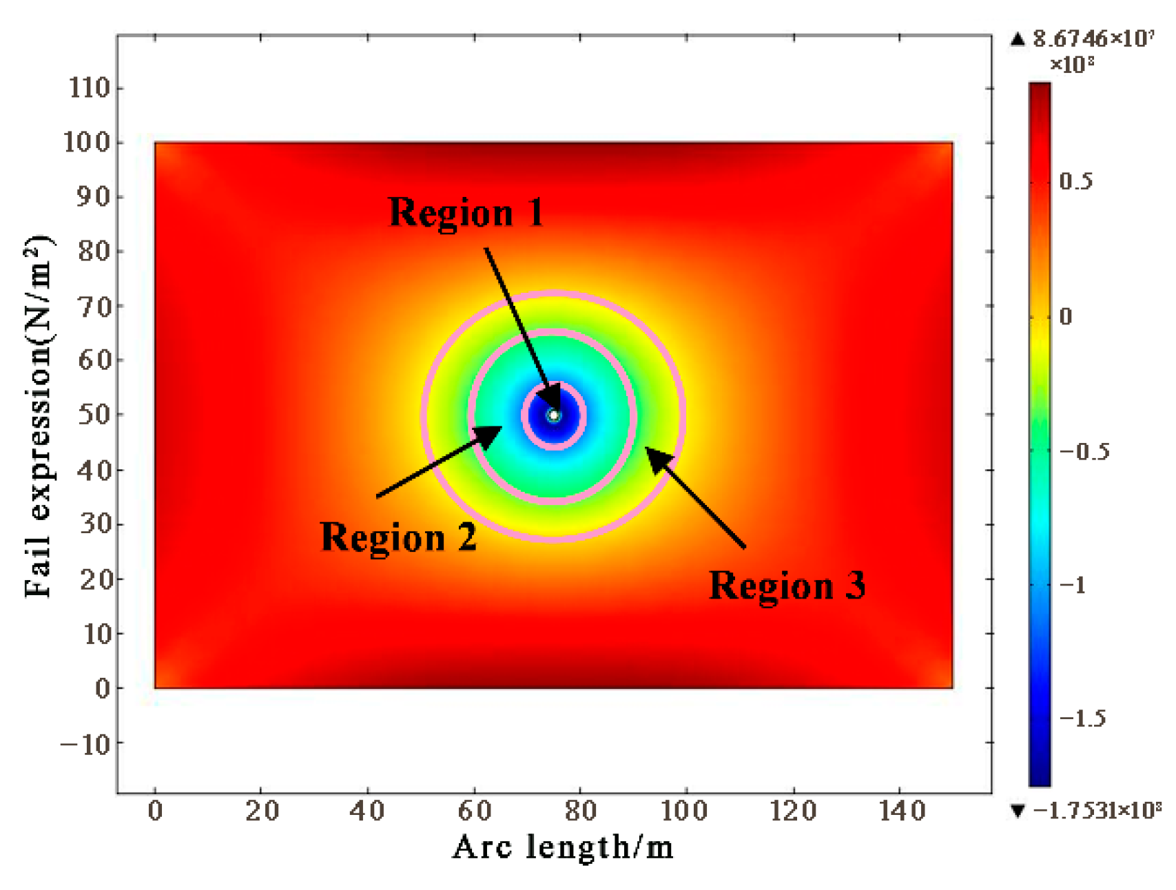
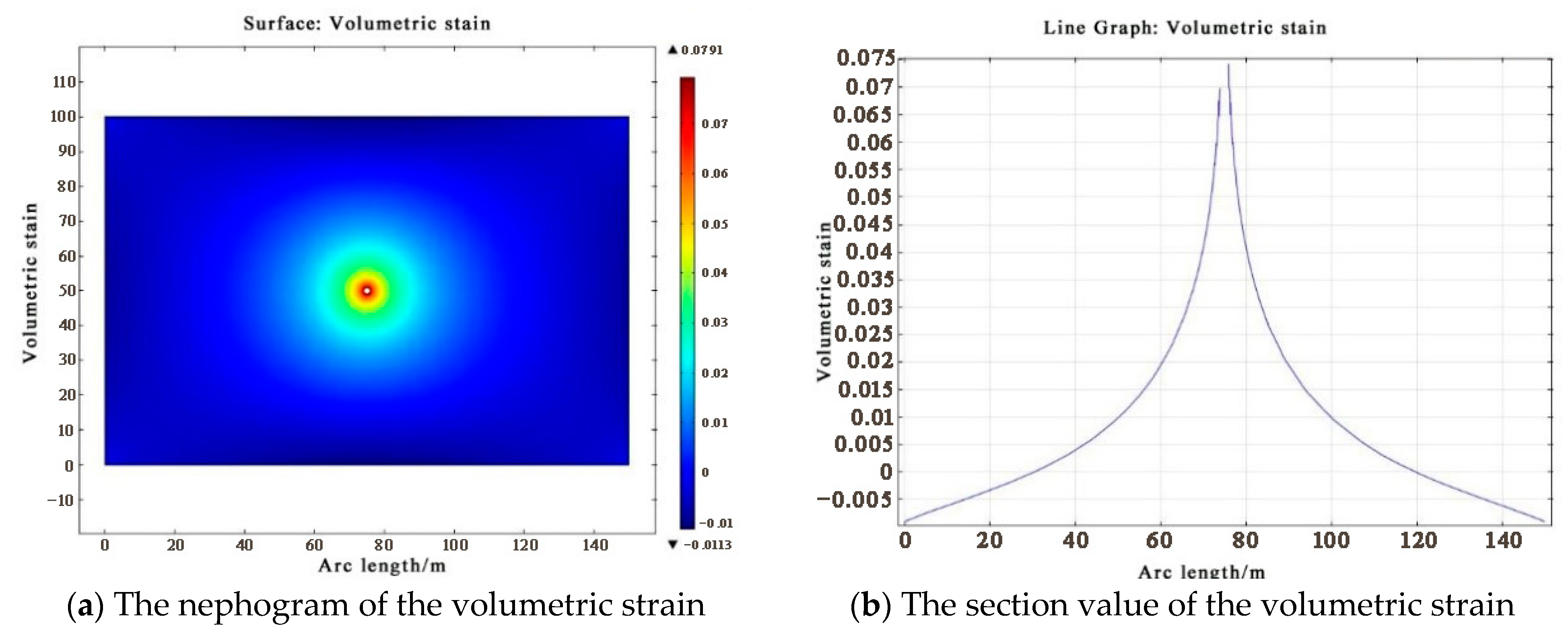
3.1. Features of the Volumetric Strain

To improve the accuracy of the division of different regions, the volumetric strain was obtained during the simulation process by COMSOL, as shown in Figure 4a. According to the position of the section line in Figure 3, the volumetric-strain contour in Figure 4a was cross-sectioned, and the result is shown in Figure 4b.
As shown in Figure 4, a gas pressure of 270 MPa was applied at the orifice, and the volumetric strain of the coal mass showed that the closer the distance to the orifice, the larger the volumetric strain. The distribution of the volumetric strain was consistent with the distribution of the plastic deformation of the coal mass. The volumetric strain in the broken circle was the largest, followed by the fissured circle, and the disturbance circle was the smallest.

3.2. Engineering Background

According to the current situation of the Baode Coal Mine, the 81,506th working face in the five-panel area was selected as the field test site for the liquid-carbon-dioxide fracturing and permeability enhancement. The 81,506th working face had a buried depth of 375 m~450 m, the original gas content was 4.6 m3/t~6.8 m3/t, the average gas content was 5.7 m3/t, and the maximum gas pressure was 1.7 MPa. The structure of the coal seam was complex, with 3–4 layers of gangue, and the average coal thickness was 8.4 m. The roof and floor strata of the coal seam are shown in Table 2.

3.3. Test Scheme

According to the numerical simulation, combined with field-construction experience, the fracturing test was carried out in the 81,506th working face. As shown in Figure 5, two types of drilling holes (fracturing boreholes and contrast boreholes) were arranged in the 81,506th working face. The fracturing boreholes were placed at intervals of 20 m in the reserved area of the 81,506th working face. The borehole depths were 220 m, 140 m, 144 m, 142 m, 125 m, and 125 m, respectively, and the borehole diameter was 113 mm. The contrast boreholes were placed in the 100 m area on both sides of the fracturing area.

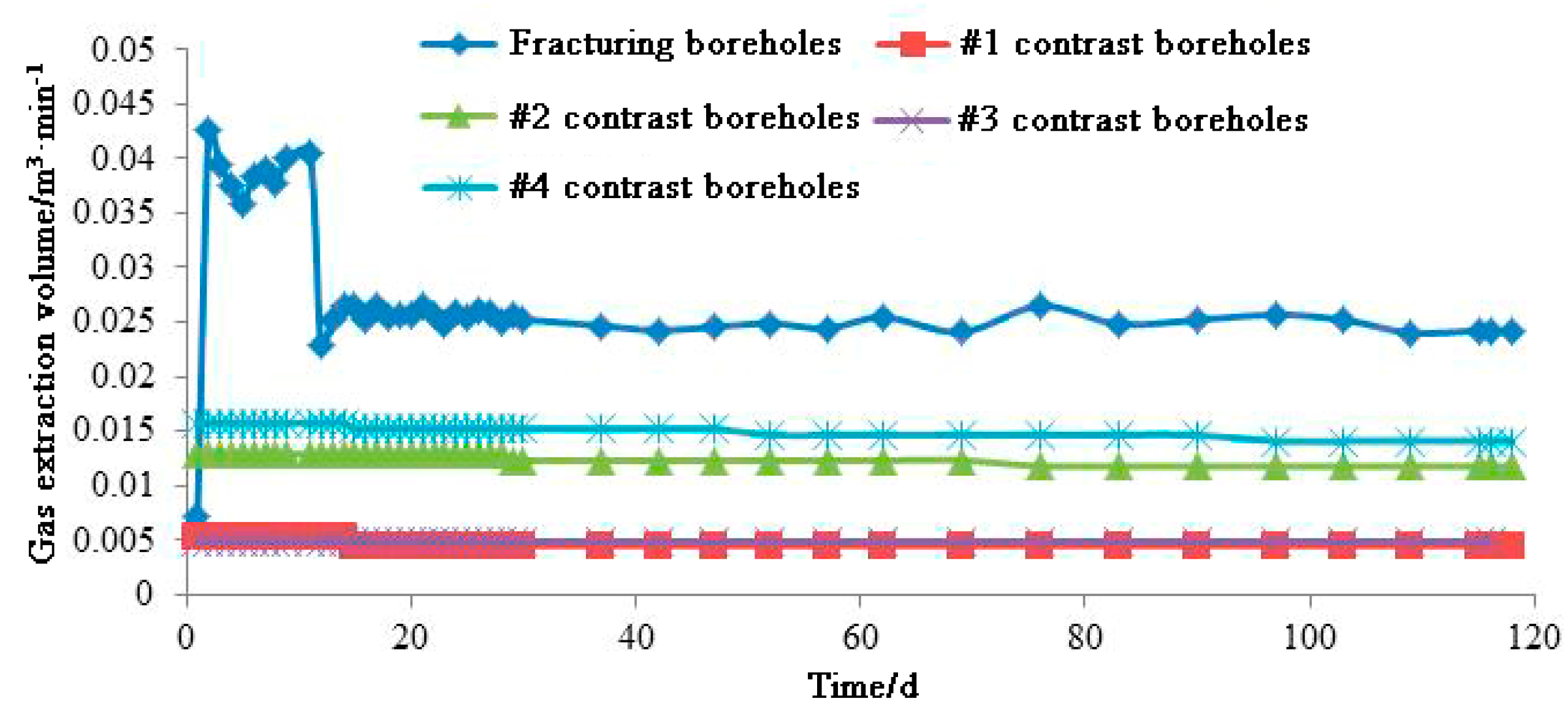
3.4. The Effect of the Fracturing

(1) The gas-extraction volume and gas-extraction concentration
The onsite-monitoring curves of the gas-extraction volume of the fracturing boreholes and contrast boreholes are shown in Figure 6.
As shown in Figure 6, the gas-drainage volume of the fracturing boreholes was significantly higher than that of the contrast boreholes during the same period. According to the onsite-monitoring data, the maximum and average values of gas drainage in the fracturing boreholes and contrast boreholes are shown in Table 3.
As shown in Table 3, the gas-extraction volume of the fracturing boreholes was 186–600% of the gas-extraction volume of the contrast boreholes, with an average of 393.9%, and the extraction effect of the fracturing boreholes was 293.9% higher than that of the contrast boreholes on average. The monitoring curves of the gas-drainage concentration in the fracturing boreholes and contrast boreholes are shown in Figure 7.
As shown in Figure 7, the gas-drainage concentration of the fracturing boreholes was close to that of the contrast boreholes with a higher gas-drainage concentration. It was significantly higher than that of the contrast boreholes with a lower gas concentration. According to the onsite-monitoring data, the maximum and average values of the gas drainage in the fracturing boreholes and contrast boreholes are shown in Table 4.
As shown in Table 4, the maximum gas-extraction concentration of the fracturing boreholes was 113.4~633.9% of the contrast boreholes, and the average value was 101.6~632.3%. The maximum and average of the gas extraction concentration of the fracturing boreholes were higher than those of the contrast boreholes, and the concentration of the gas drainage increased by 242.4% on average.
(2) The index of the amount of gas desorption
In the 81,506th haulage roadway, the value of the amount of gas desorption (K1) was determined in the fracturing zone and the contrast zone. The onsite monitoring data are shown in Table 5.
As shown in Table 5, the values of K1 of the coal mass in the fracturing zone and the contrast zone were all reduced. The maximum value of the K1 was reduced by 0.11 mL/g·min1/2, a decrease of 64.7%, after 3 months of gas discharge in the coal mass in the fracturing zone. However, the maximum value of the K1 was reduced by 0.04 mL/g·min1/2, a decrease of 19.1%, after 3 months of gas discharge in the coal mass in the contrast zone. The onsite data showed that the decreased degree of the value of the K1 of the coal mass in the fracturing zone was significantly larger than in the contrast zone. It showed that the fracture effect of the liquid CO2 phase transition was significant.
(3) Coal-seam permeability coefficient
The coal-seam gas content was measured before and after fracturing, and the natural gas flow rate of the borehole was measured. The coal-seam permeability coefficient before and after fracturing the coal seam in the #3 and #5 panels are shown in Table 6.
As shown in Table 6, the permeability coefficient of the coal seam increased by 3–7.75 times after fracturing, and the effect of increasing the permeability coefficient of the coal seam by liquid-carbon-dioxide fracturing was obvious.

3.5. Analysis of the Test Results

According to the field test data, the conclusions were as follows:
(1) In the first month after carbon-dioxide fracturing in the 81,506th working face of the #5 panel, the gas-extraction volume increased by 306% compared with the contrast boreholes; four months after fracturing, the gas-drainage volume of the fracturing boreholes increased by 293.9% compared with the contrast boreholes.
(2) The maximum and average values of the gas extraction concentration in the fracturing boreholes were both greater than those in the contrast boreholes. The average gas concentration of the fracturing boreholes was 1.76 times that of the contrast boreholes, constituting an average increase of 242.4%.
(3) The maximum value of the K1 was reduced by 0.11 mL/g·min1/2, a decrease of 64.7%, after 3 months of gas discharge in the coal mass in the fracturing zone. However, the maximum value of the K1 was reduced by 0.04 mL/g·min1/2, showing a decrease of 19.1%, after 3 months of gas discharge in the coal mass in the contrast zone.
(4) After fracturing, the permeability coefficient of the coal seam increased by 3–7.75 times, and the effect of the increase in the permeability coefficient of the coal seam by carbon-dioxide fracturing was obvious.

4. Conclusions

In this paper, the mechanism of the liquid-carbon-dioxide fracturing of the coal seam to enhance permeability was studied. The COMSOL software was used to numerically analyze the influence radius of the liquid-carbon-dioxide phase-transition fracturing, which provided a basis for reasonable field-distribution parameters and an analysis of the effect of the onsite liquid-carbon-dioxide fracturing. The main conclusions were as follows:
(1) The technology of liquid-carbon-dioxide fracturing of the coal seam enhanced the permeability through three aspects. First, the action of stress waves caused new cracks in the coal mass, and stress concentration occurred at the tip of the crack, which promoted the expansion and development of tiny cracks. Second, the intrusion of the high-pressure liquid-carbon-dioxide gas into the coal, resulted in cutting, impact, and a gas wedge. Third, the carbon dioxide gas broke through the constant pressure valve, and a large expansion thrust was generated, which acted on the coal mass, generating new cracks and disturbing the primary cracks in the coal seam.
(2) The COMSOL software was used to simulate the influence radius of the liquid carbon dioxide cracking, and it was determined that with the geological conditions of the #8 coal seam in the Baode Coal Mine, the influence radius of the carbon-dioxide phase transition cracking was 13.4 m.
(3) The gas-extraction volume, gas concentration, index of the amount of gas desorption and coal-seam permeability coefficient of the fracturing hole and the contrast hole were monitored onsite. The results showed that the fracturing effect was good.

Funding

This research was financially supported by the Higher Educational Scientific Research Projects of Inner Mongolia Autonomous Region (No. NJZY21291).

Institutional Review Board Statement

Not applicable.

Informed Consent Statement

Not applicable.

Data Availability Statement

All data included in this study are available upon request by contacting the corresponding author.

Acknowledgments

We are grateful to anonymous reviewers for their constructive reviews on the manuscript, and the editors for carefully revising the manuscript.

Conflicts of Interest

The author declares no conflict of interest.

References

  1. Kang, X.B.; Luo, S.; Li, Q.S.; Xu, M.; Li, Q. Developing a risk assessment system for gas tunnel disasters in China. J. Mt. Sci. 2017, 14, 1751–1762. [Google Scholar] [CrossRef]
  2. Wang, K.; Du, F. Coal-gas compound dynamic disasters in China: A review. Process Saf. Env. 2020, 133, 1–17. [Google Scholar] [CrossRef]
  3. Chen, X.J.; Li, L.Y.; Wang, L.; Qi, L. The current situation and prevention and control countermeasures for typical dynamic disasters in kilometer-deep mines in China. Safety Sci. 2019, 155, 229–236. [Google Scholar] [CrossRef]
  4. Hu, G.Z.; Sun, C.; Sun, M.F.; Qin, W.; Linghu, J. The case for enhanced coalbed methane using hydraulic fracturing in the geostructural belt. Energy Explor. Exploit. 2018, 36, 1629–1644. [Google Scholar] [CrossRef]
  5. Lu, W.; He, C. Numerical simulation of the fracture propagation of linear collaborative directional hydraulic fracturing controlled by pre-slotted guide and fracturing boreholes. Eng. Fract. Mech. 2020, 235, 107128. [Google Scholar] [CrossRef]
  6. Yang, W.; Lu, C.; Si, G.; Lin, B.; Jiao, X. Coal and gas outburst control using uniform hydraulic fracturing by destress blasting and water-driven gas release. J. Nat. Gas Sci. Eng. 2020, 79, 103360. [Google Scholar] [CrossRef]
  7. Wang, Y.; Yu, Z.; Wang, Z. A Mechanical Model of Gas Drainage Borehole Clogging under Confining Pressure and Its Application. Energies 2018, 11, 2817. [Google Scholar] [CrossRef]
  8. Sun, X.; Cheng, Z.; Chen, L.; Li, Z.; Wang, H.; Yin, S. Deflection Laws of Gas Drainage Boreholes in Interbedded Soft and Hard Seams: A Case Study at Xinzheng Coal Mine, China. Adv. Civ. Eng. 2021, 2021, 1–11. [Google Scholar] [CrossRef]
  9. Hu, C.; Li, Q.; Wang, Y.; Li, Y.; Wang, Y.; Chang, K. Influence Mechanism of Mine Pressure on Coal Seam Gas Emission During Mining. Geotech. Geol. Eng. 2022, 40, 3067–3074. [Google Scholar] [CrossRef]
  10. Zhang, Y.A.; Deng, J.R.; Deng, H.W.; Ke, B. Peridynamics simulation of rock fracturing under liquid carbon dioxide blasting. Int. J. Damage Mech. 2019, 28, 1038–1052. [Google Scholar] [CrossRef]
  11. Xia, J.Q.; Dou, B.; Tian, H.; Zheng, J.; Cui, G.; Kashif, M. Research on initiation of carbon dioxide fracturing pipe using the liquid carbon dioxide phase-transition blasting technology. Energies 2021, 14, 521. [Google Scholar] [CrossRef]
  12. Chen, H.-D.; Wang, Z.-F.; Qi, L.-L.; An, F.-H. Effect of liquid carbon dioxide phase change fracturing technology on gas drainage. Arab. J. Geosci. 2017, 10, 314. [Google Scholar] [CrossRef]
  13. Zhang, Y.; Deng, J.; Ke, B.; Deng, H.; Li, J. Experimental Study on Explosion Pressure and Rock Breaking Characteristics under Liquid Carbon Dioxide Blasting. Adv. Civ. Eng. 2018, 2018, 1–9. [Google Scholar] [CrossRef]
  14. Ishida, T.; Aoyagi, K.; Niwa, T.; Chen, Y.; Murata, S.; Chen, Q.; Nakayama, Y. Acoustic emission monitoring of hydraulic fracturing laboratory experiment with supercritical and liquid CO2. Geophys. Res. Lett. 2012, 39. [Google Scholar] [CrossRef]
  15. Niezgoda, T.; Miedzinska, D.; Malek, E. Study on carbon dioxide thermodynamic behavior for the purpose of shale rock fracturing. Bull. Pol. Acad. Sci. Tech. Sci. 2013, 61, 605–612. [Google Scholar] [CrossRef]
  16. Cui, X.J.; Ke, B.; Yu, S.T.; Li, P.; Zhao, M. Energy characteristics of seismic waves on Cardox Blasting Tube. Geofluids 2021, 2021, 1–13. [Google Scholar] [CrossRef]
  17. Pan, Z.J.; Connell, L.D. A theoretical model for gas adsorption-induced coal swelling. Int. J. Coal Geol. 2007, 69, 243–252. [Google Scholar] [CrossRef]
  18. Gorgulu, K.; Arpaz, E.; Uysal, O.; Durutürk, Y.S.; Yüksek, A.G.; Koçaslan, A.; Dilmaç, M.K. Investigation of the effects of blasting design parameters and rock properties on blast-induced ground vibrations. Arab. J. Geosci. 2015, 8, 4269–4278. [Google Scholar] [CrossRef]
  19. Lekontsev, Y.M.; Sazhin, P.V. Directional hydraulic fracturing in difficult caving roof control and coal degassing. J. Min. Sci. 2014, 50, 914–917. [Google Scholar] [CrossRef]
  20. Lisienko, V.G.; Lapteva, A.V.; Chesnokov, Y.N.; Zagainov, S. Comparative Analysis of the Influence of Fuel Injection on the Energy Intensity and Carbon Footprint of the Blast-Furnace Process. Metallurgist 2017, 61, 183–187. [Google Scholar] [CrossRef]
  21. Cheng, X.; Zhao, G.M.; Li, Y.M. Key technologies and engineering practices for soft-rock protective seam mining. Int. J. Min. Sci. Technol. 2020, 30, 889–899. [Google Scholar] [CrossRef]
  22. Behnoudfar, P.; Asadi, M.B.; Gholilou, A.; Zendehboudi, S. A new model to conduct hydraulic fracture design in coalbed methane reservoirs by incorporating stress variations. J. Pet. Sci. Eng. 2019, 174, 1208–1222. [Google Scholar] [CrossRef]
  23. Li, Q.; Wang, Y.L.; Owusu, A.B. A modified Ester-branched thickener for rheology and wettability during CO2 fracturing for improved fracturing property. Environ. Sci. Pollut. Res. 2019, 26, 20787–20797. [Google Scholar] [CrossRef] [PubMed]
  24. Liao, Z.W.; Liu, X.F.; Song, D.Z.; He, X.; Nie, B.; Yang, T.; Wang, L. Micro-structural damage to coal induced by liquid CO2 phase change fracturing. Nat. Resour. Res. 2020, 30, 1613–1627. [Google Scholar] [CrossRef]
  25. Liu, H.; Wang, F.; Zhang, J.; Meng, S.; Duan, Y. Fracturing with carbon dioxide: Application status and development trend. Pet. Explor. Dev. 2014, 41, 513–519. [Google Scholar] [CrossRef]
  26. Rogala, A.; Ksiezniak, K.; Krzysiek, J.; Hupka, J. Carbon dioxide sequestration during shale gas recovery. Physicochem. Probl. Miner. Process. 2014, 50, 681–692. [Google Scholar]
  27. Yang, Z.Z.; Yi, L.P.; Li, X.G.; Li, Y.; Jia, M. Phase control of downhole fluid during supercritical carbon dioxide fracturing. Greenh. Gases Sci. Technol. 2018, 8, 1079–1089. [Google Scholar] [CrossRef]
  28. Hu, C.; Yang, X.; Huang, R.; Ma, X. Presplitting Blasting the Roof Strata to Control Large Deformation in the Deep Mine Roadway. Adv. Civ. Eng. 2020, 2020, 1–15. [Google Scholar] [CrossRef]
  29. Fan, C.; Li, S.; Luo, M.; Yang, Z.; Lan, T. Numerical simulation of hydraulic fracturing in coal seam for enhancing underground gas drainage. Energy Explor. Exploit. 2019, 37, 166–193. [Google Scholar] [CrossRef]
  30. Reisabadi, M.Z.; Sayyafzadeh, M.; Haghighi, M. Stress and permeability modelling in depleted coal seams during CO2 storage. Fuel 2022, 325, 124958. [Google Scholar] [CrossRef]
  31. Qu, Q.; Shi, J.; Wilkins, A. A Numerical Evaluation of Coal Seam Permeability Derived from Borehole Gas Flow Rate. Energies 2022, 15, 3828. [Google Scholar] [CrossRef]
  32. Yang, X.; Hu, C.; Liang, J.; Zhou, Y.; Ni, G.; Huang, R. A Case Study on the Control of Large Deformations in a Roadway Located in the Du’erping Coal Mine in China. Adv. Mater. Sci. Eng. 2019, 2019, 1–13. [Google Scholar] [CrossRef]
  33. Jovanovic, A.P.; Stankov, M.N.; Loffhagen, D.; Becker, M.M. Automated fluid model generation and numerical analysis of dielectric barrier discharges using Comsol. IEEE Trans. Plasma Sci. 2021, 49, 3710–3718. [Google Scholar] [CrossRef]
  34. Hu, C.; Liu, W.; Wang, Y. Study on the Influence of the Location of Dirt Band on Top Coal Caving Property in Extra-Thick Coal Seam. Geotech. Geol. Eng. 2020, 38, 6221–6230. [Google Scholar] [CrossRef]
  35. Jha, P.K.; Lipton, R.P. Kinetic relations and local energy balance for LEFM from a nonlocal peridynamic model. Int. J. Fract. 2020, 226, 81–95. [Google Scholar] [CrossRef]
Figure 1. Numerical simulation model of phase transformation cracking.
Sustainability 15 03308 g001
Figure 2. Plastic deformation.
Sustainability 15 03308 g002
Figure 3. Division of the plastic deformation zone.
Sustainability 15 03308 g003
Figure 4. The volumetric strain.
Sustainability 15 03308 g004
Figure 5. The arrangement of the boreholes.
Sustainability 15 03308 g005
Figure 6. The arrangement of the boreholes.
Sustainability 15 03308 g006
Figure 7. Monitoring curves of the gas-drainage concentration.
Sustainability 15 03308 g007
Table 1. The parameters of the model.
SymbolParameterValueUnit
ρ1Density of coal seam1490kg/m3
EElastic modulus2 × 109Pa
VPoisson ratio0.35
KPermeability10−17m2
K1Porosity6.58%
cCohesion4MPa
φInternal friction angle33°
ρ2Density of CO21.977kg/m3
μDynamic viscosity of CO21.48 × 10−5Pa·s
ZCompressibility factor of CO21.02
Table 2. The roof and floor strata of the coal seam.
StrataLithologyThickness/m
Main roofMedium sandstone, Mudstone10
Immediate roofSiltstone, Sandy mudstone8.4
Immediate floorSiltstone5.6
Main floorGrit stone5.3
Table 3. Gas drainage volume of fracturing boreholes and contrast boreholes.
LocationTypeGas Drainage Volume
Maximum ValueMean Value
Fracturing zoneFracturing boreholes0.04260.0276
#1 Contrast zone#1 contrast boreholes0.00520.0046
#2 contrast boreholes0.01290.0122
#2 Contrast zone#3 contrast boreholes0.00490.0049
#4 contrast boreholes0.01580.0148
Table 4. Gas-drainage concentration of fracturing boreholes and contrast boreholes.
LocationTypeGas Drainage Concentration/%
Maximum ValueMean Value
Fracturing zoneFracturing boreholes7162.3
#1 Contrast zone#1 contrast boreholes11.29.9
#2 contrast boreholes56.455
#2 Contrast zone#3 contrast boreholes12.412
#4 contrast boreholes62.661.6
Table 5. The value of the amount of gas desorption (K1).
LocationTypeSample DepthK1 (mL/g·min1/2)Decreased Degree
ValueMaximum Value
Fracturing zoneWithout extraction2 m0.050.1764.7%
4 m0.12
6 m0.09
8 m0.17
10 m0.11
With
extraction
2 m0.080.06
4 m0.06
6 m0.03
8 m0.02
10 m0.05
Contrast zoneWithout extraction2 m0.030.2119.1%
4 m0.15
6 m0.10
8 m0.21
10 m0.10
With
extraction
2 m0.080.17
4 m0.17
6 m0.10
8 m0.04
10 m0.11
Table 6. The coal seam permeability coefficient.
LocationThe Coal Seam Permeability Coefficient m2/MPa2·dMultiple
Before FracturingAfter Fracturing
#3 panel0.0527550.1590583.01
#5 panel0.0308460.239157.75
Disclaimer/Publisher’s Note: The statements, opinions and data contained in all publications are solely those of the individual author(s) and contributor(s) and not of MDPI and/or the editor(s). MDPI and/or the editor(s) disclaim responsibility for any injury to people or property resulting from any ideas, methods, instructions or products referred to in the content.

