Abstract
Significant stress changes caused by sorption-induced swelling raise the coal wellbore failure potential, which directly impacts the safety and sustainability of CO2 enhanced coalbed methane (CO2-ECBM). Additionally, a mixture gas (CO2/N2) injection is recommended due to the sharp decline of permeability with pure CO2 injection. In this study, incorporating the impacts of mixture gas adsorption and poroelastic effects, a semi-analytical model of coal wellbore stability during mixture gas injection is proposed. Model results indicate that the stress field is significantly influenced by the boundary condition and sorption effect. In addition, parametric studies are performed to determine the influence of adsorption parameters, mechanical properties, and gas composition on the stress distribution and then on the wellbore failure index. Furthermore, mixture gas injection with a large proportion of CO2 or N2 both cause wellbore instability. Significant compressive hoop stress and shear failure are caused by the mixture gas injection with a large proportion of CO2. In contrast, the displacement of CH4 with weakly adsorptive N2 will result in less compressive and even tensile hoop stress, so shear or tensile failure may occur. Thus, mixture gas (including pure CO2/N2) injection must be controlled by coal wellbore failure, providing an accurate estimation of in-situ coal seams’ CO2 storage capacity from the perspective of wellbore stability.
1. Introduction
Since 95–98% of the total gas can be stored as absorbed gas in the microporous structure [1], deep, unmineable coalbeds with enormous CO2 storage capacity are considered to be an appealing alternative for carbon dioxide receptacles [2,3]. While large-scale carbon capture and storage (CCS) must evaluate all potential modes of failure, stress changes due to CO2 injection need to be limited [4]. In addition, significant stress changes caused by sorption-induced swelling also raise the coal failure potential [5], which directly impacts the safety and sustainability of CO2-ECBM.
Coal failure during coalbed methane production has received a lot of attention from researchers, whereas coal failure during CO2-ECBM has received less attention. Shi and Durucan [6] initially estimated the effective stress change during depletion using an analogy between thermal contraction and gas desorption-induced matrix shrinkage, and experimental data demonstrate excellent agreement [7]. Liu and Harpalani [8] provided an experimental investigation of the horizontal stress variations, and discovered that in addition to the poroelastic effect seen in conventional reservoirs, sorption-induced shrinkage also alters in-situ stress and increases coal failure potential. Additionally, experimental studies revealed that gas with a higher adsorption capacity corresponds to a greater horizontal stress loss in depletion [9,10]. This in turn suggests that CO2 injection would result in a greater horizontal stress change. The reservoir-scale failure of CO2-ECBM was explored by Lu and Connell [11], who noted that stress changes are complex phenomena connected to reservoir pressure, gas mix, and adsorption parameters. Above all, however, these models account for constant vertical stress and a uni-axial strain condition. Due to the non-uniform pore pressure distribution in the reservoir, a numerical method was devised to discover that the common uni-axial strain condition has significant deviations in the coal failure analysis [12]. In order to properly analyze coal failure during CO2-ECBM, non-uniform pore pressure distribution, adsorption characteristics, and gas composition must all be taken into account.
Furthermore, shear failure in the reservoir formation is promoted by near-wellbore stress concentration [13]. In addition, local wellbore failure occurred before reservoir-scale coal failure [14]. So, a basis for the safe CO2-ECBM or sequestration is wellbore stability rather than coal stability, and it can provide an upper limit for CO2 storage capacity. Cui et al. [15] developed analytical solutions of the stress field under the uni-aixal strain, general stress, and plane strain conditions, shedding light on the stress distribution in a reservoir with an isotropic horizontal stress state. In the process of CBM depletion, Reisabadi et al. [16] examined the distinct coal failure index of the coal seams under various stress regimes. Masoudian et al. [17] simulated the stress change in coal with respect to the effect of the sorption-induced modification on mechanical behavior. Hu et al. [18] also developed a model for the cement-formation interface failure length during CO2-ECBM, demonstrating the importance of the injection rate in determining the interface failure.
Furthermore, pure CO2 injection causes more sorption stress and permeability decline than N2, so injecting a CO2/N2 mixture gas is recommended. Li and Elsworth [19] discovered that a higher proportion of CO2 in the injected CO2/N2 mixture results in lower shale gas recovery. Wen et al. [20] investigated the process of CO2 gas replacing CH4 using low-field NMR technology, and the effects of injection pressure and temperature were analyzed. Moreover, a micro pilot test of underground displacement using N2 injection demonstrated a significant stimulation effect when compared to a conventional emission test [21]. However, various adsorptive gases cause various sorption stresses, which change the formation and wellbore stability to a different extent. To the best of the authors’ knowledge, wellbore stability of coal seams with anisotropic stress state during mixture gas injection (including pure CO2/N2) has not been thoroughly studied.
In this study, a semi-analytical method was applied to investigate the wellbore failure index during reservoir-scale CO2-ECBM assuming zero displacement at the outer boundary condition and plane-strain condition near the wellbore. Furthermore, steady reservoir pressure distribution is assumed to simply simulate the mixture gas (or pure CO2) injection process. The analytical total stress field is derived by considering sorption-induced swelling and poroelastic effect, superposing the stress caused by in- situ stress, borehole pressure, reservoir pressure distribution, and gas adsorption. The critical borehole pressure and gas component (CBPGC) is calculated by combining the Mogi–Coulomb failure criterion with the total stress field. The CBPGC can serve as a benchmark for numerical simulation and quick assessment of the CO2 storage capacity of in- situ coal seams.
2. Model Development
The coal is a porous medium and adsorbent in which the stress state changes as the reservoir pressure and adsorption amount vary during CO2-ECBM. In addition, the initial in- situ stress state, including the reservoir pressure, is essential to determine the ultimate stress state and failure potential. In this study, a wellbore with a radius of covering a cylindrical domain with a radius of is considered.
2.1. Stress–strain Constitutive Equation
Gases such as N2, CH4, and CO2 are absorbed primarily on the internal surface of microporous coal particles, causing significant matrix swelling. Using and extending Cui’s model [15], the volumetric strain associated with mixture gas sorption can be written as follows
where
Additionally, and are the Langmuir-type swelling constants of gas i, which represent the maximum swelling capacity and the pore pressure at which the volumetric strain is equal to , respectively [22,23]. Additionally, Langmuir-type swelling constants differ from Langmuir-type adsorption constants: and [9]. Additionally, is the mole fraction of gas component i in free gas mixture, p is the reservoir (pore) pressure. Moreover, Cui et al. [15] established a relationship by using the experiment data: with volumetric strain coefficient of gas i, which gave similar values to those of Liu et al. [9]. In addition, is the initial volumetric strain caused by CH4 adsorption in the initial state, and is the initial reservoir pressure.
The pressure variation during CO2-ECBM has two impacts on effective horizontal stresses. In addition to the poroelastic (poromechanical) effect, the sorption-induced matrix shrinkage/swelling also modifies the effective horizontal stresses. Similar to the constitutive law of the non-isothermal poroelastic medium, the constitutive equations of coal seam considering sorption can read [9,15,22,23],
where E is Young’s modulus of porous medium, is Poisson’s ratio, is the bulk volumetric strain, is Kronecker’s delta and i or j is the directional index in cylindrical coordinates. Additionally, is the Biot constants, which are assumed to be one due to the large amount of cleats and fractures in the coal.
2.2. Analytical Model of Stress Distribution around the Wellbore
The total stresses around the borehole during the CO2-ECBM can be split into the two categories below: (1) Mode 1: the stresses induced by the in-situ principal stresses and the bottom-hole pressure, which is significant near the wellbore and referred to the “near wellbore effect”; (2) Mode 2: additional stresses due to fluid flow and gas sorption. Then, the analytical solution of the total stress around the wellbore can be obtained by superposition.
2.2.1. Simplifications and Assumptions
For the gas injection, the reservoir pressure, gas concentration, and stress will change transiently. While as the gas injection continues, the reservoir pressure profile approaches a steady state, which is considered here and allows us to obtain simple solutions and a perceptive understanding. Differing to Cui’s assumptions [15], the anisotropic in-situ stress state and depleted reservoir is considered here. The assumptions conclude:
- (1)
- The tectonic stress affects the coal seams and the initial in-situ stress is anisotropic;
- (2)
- A steady reservoir pressure profile changing logarithmically from a constant borehole pressure at the wellbore () to a reservoir pressure at the outer boundary ();
- (3)
- Gas injection can occur after depletion, in which case the reservoir pressure is unequal to the initial value before depletion ();
- (4)
- A zero displacement at the outer boundary rather than each point (common uni-axial strain model) in the reservoir [15];
- (5)
- A plane strain condition near the wellbore and a constant overburden far from the wellbore [14];
- (6)
- At the final steady state, uniform gas composition of the injected gas is achieved.
2.2.2. Mode 1: Stresses Induced by the Initial In-Situ Stress and Borehole Pressure
According to the classical Kirsch solution, the stress distribution around the wellbore for a vertical wellbore is given as [14,24,25]
where is the borehole pressure, is the angular position around the wellbore. are the initial maximum, minimum horizontal and vertical stresses, which are determined by stress measurement in the initial in-situ state before depletion/depressurization. Additionally, the superscript “1, 2” denotes the stresses induced by the Mode 1 and 2, respectively.
2.2.3. Mode 2: Stresses Induced by Poroelastic Response and Gas Adsorption
When mixture gas (CO2/N2) is gradually injected into the coal seams, the pore pressure eventually approaches a steady state, from which we can derive an analytical solution. Assuming that the wellbore has a radius covering a cylindrical domain with a radius and a constant pressure, is fixed before injection, then the incremental steady reservoir pressure distribution relative to the initial reservoir pressure can be approximated as [15,26]
where is borehole pressure, is the uniform reservoir pressure before mixture gas injection in the coal seams. It should be noted that appropriate injection timing can continue to the time when coal fails in depletion, so can be assumed. The incremental volumetric strain due to displacement of CH4 with CO2/N2 can be described by the extended Langmuir model as
Then, the isotropic elastic constitutive law in the incremental form of Equation (3) in the cylindrical coordinates reads
With
The stress equilibrium equation in Mode 2 is given as
Combining Equations (7) and (8) with Equation (9), we can obtain the incremental radial displacement
Then, integrating Equation (10) two times yields the solution
Then, induced radial, hoop stress due to fluid flow and gas sorption in the incremental form of Mode 2 is derived as follows
With
where . Additionally, can be solved by the imposed boundary conditions. In addition, the term in Equations (14) and (15) denotes the poroelastic and sorption effect on the radial and hoop stresses in Equations (12) and (13), respectively. When a stress boundary condition at the borehole wall and zero displacement condition () at the outer boundary (ZDBC) is specified, we can obtain from Equations (11) and (12)
When a constant stress boundary condition () at the borehole wall and outer boundary (ZSBC) is specified, i.e., no lateral constrain at the outer boundary, from Equations (11) and (12) we can obtain
The incremental stress equations derived here are similar to those developed by Cui et al. [15] in absolute form of total stress. However, Cui’s model cannot study the wellbore stability of the coal seams with anisotropic in-situ stress state. In addition, CO2 is often injected into the depleted coal seams, i.e., the reservoir pressure before injection is not equal to the initial reservoir pressure (). Additionally, the present model can deal with the situation.
2.2.4. The Total Stresses around the Wellbore with Anisotropic In-Situ Stress
Ultimately, the complete solution of stress field around a vertical wellbore during the CO2-ECBM process can be obtained by superposition
Under the linear elastic theory, the maximum stress concentration and then failure index usually appears at the wellbore wall [27,28]. So stress distribution and the following failure index can be studied at the borehole wall. Then, the total stresses at the wellbore wall can be given as
2.3. Failure Criterion
Additionally, an appropriate shear failure criterion for wellbore stability should be applied for coal failure evaluation. The Mogi–Coulomb failure criterion, considering the effect of intermediate principal stress, can match well with field data [14,16,29]. In this study, the Mogi–Coulomb failure criterion is used to forecast coal failure during CO2-ECBM [14].
where are the rock cohesion and friction angle, and , , respectively. It should be noted that the in Equations (19)–(21) are the principal stresses at the borehole, since shear stresses at the borehole are .
Then, the total stresses are substituted into the failure criterion to obtain the critical borehole pressure and gas component (CBPGC), defining the critical allowable with specific gas components in terms of wellbore stability during CO2-ECBM.
3. Induced Stress during CO2-ECBM and Parametric Analysis
Differing to the conventional reservoir, except for the poroelastic response, the swelling during adsorptive gas injection causes tremendous stress change, which is not well studied during CO2-ECBM. So the stress change considering the poroelastic and adsorptive effect during mixture gas (CO2/N2) injection must be carefully researched. Additionally, the influencing factors’ effect on the induced stress is also studied. Table 1 presents the typical input data in this study.

Table 1.
Input parameters for simulation [9,15,16].
3.1. Model Verification
This paper aims to use the superposition method to provide an analytical solution considering the anisotropic in-situ stress state in the coal seams. Figure 1 illustrates the great agreement between the model results for the induced effective stress change and radial displacement due to CO2 injection and Cui’s model [15], verifying the accuracy of the present model. The induced effective horizontal stress change in Figure 1a can be given as because the induced effective stress change is caused by fluid flow and sorption. Furthermore, the ZDBC (zero displacement at the outer boundary) condition restricts the lateral deformation and results in an order-of-magnitude difference in radial displacement (seen in Figure 1b) compared to the ZSBC (zero stress change at the outer boundary). As a result, a more significant stress change is induced during CO2-ECBM.
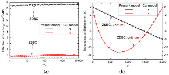
Figure 1.
Profiles of (a) effective horizontal stress change and (b) induced radial displacement during pure CO2 injection between the present model and results by Cui et al. [15]. ZDBC and ZSBC denote zero displacement and zero stress change at the outer boundary, respectively.
3.2. The Stress Caused by Poroelastic Response and Gas Adsorption
In contrast to conventional reservoirs, sorption-induced swelling results in a large shift in the reservoir’s stress, excluding the poroelastic effect. Figure 2 displays the variations between induced stress and radial displacement whether sorption is considered or not, emphasizing the significance of doing so. It should be noted that the steady reservoir pressure distribution results in negative (tensile) radial and hoop stresses, when only the poroelastic effect is considered, while compressive radial and hoop stresses are induced, including the sorption effect as shown in Figure 2a. The swelling/volumetric strains induced by the sorption of CO2 and CH4 are different, and then the displacement of CH4 by CO2 causes tremendous net swelling. However, the zero displacement at the outer boundary condition overwhelmingly restricts the coal to accommodate the net swelling. In contrast, the induced displacement, considering the sorption effect, is one order more than that merely considering the poroelastic effect in Figure 2b. Thus, considering the strong swelling and boundary condition, the stress state in the whole domain is markedly elevated in Figure 2a. Furthermore, the maximum radial and hoop stresses occur at the borehole; thus, reservoir instability can be analyzed using the wellbore stability issue. Additionally, the incremental reservoir pressure distribution in Equation (6), rather than the real reservoir pressure distribution, causes the stresses change.
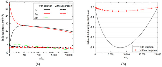
Figure 2.
(a) The induced stress and (b) radial displacement difference with normalized radial distance considering sorption or not. In this case, pure CO2 is injected by 12 MPa with reservoir pressure before injection 3 MPa and ZDBC condition is imposed.
From Equations (12)–(15), with the exception of the reservoir pressure distribution (), the induced stress is clearly controlled by the mechanical properties (), adsorption parameters (), and gas component of CO2 (). Then, the parametric analysis of corresponding factors’ effect on the induced stress is made as follows.
3.2.1. The Influence of Langmuir-Type Constants ()
The influence of adsorption parameters on the distribution of the radial, hoop and effective horizontal stress variation with normalized radial distance in pure CO2 injection is displayed in Figure 3. Both adsorption parameters severely affect the stress distribution and subsequent wellbore instability. Additionally, we may deduce that the more and less , the higher the radial, hoop, and effective horizontal stresses can be generated. While the result differs from that under common uni-axial strain condition [15], the induced effective horizontal stress under ZDBC condition varies little throughout the radial distance in some circumstances.
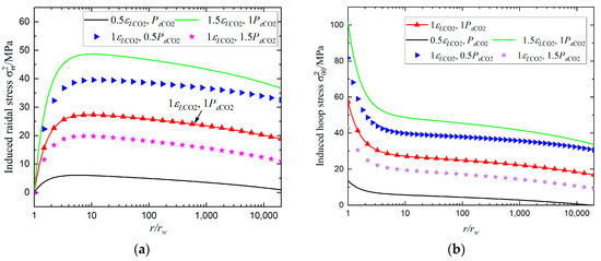
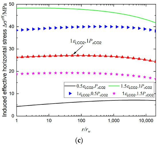
Figure 3.
Profiles of (a) induced radial stress, (b) hoop stress and (c) effective horizontal stress distribution with varying adsorption parameters. In this case, pure CO2 is injected by 12 MPa with 3 MPa and ZDBC condition is imposed.
3.2.2. The Influence of Young Modulus and Poisson Ratio of Coal
The influence of mechanical properties on the induced radial, hoop and effective horizontal stress distribution is depicted in Figure 4. The maximum values of induced radial, hoop and effective horizontal stresses grow as the Young modulus and Poisson ratio increase. In addition, the Poisson ratio has less substantial effect on the stress distribution than the Young modulus, as shown in Figure 4. Consequently, sorption-induced stress should be given more consideration in coal seams and shale with a high Young modulus and Poisson ratio.
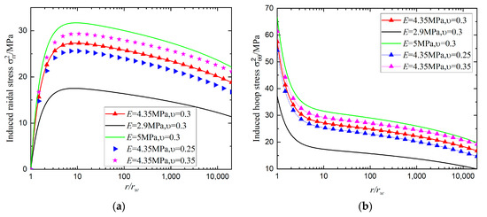
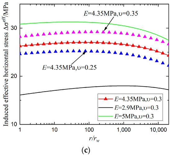
Figure 4.
Profiles of induced (a) radial stress, (b) hoop stress and (c) effective horizontal stress distribution with varying Young modulus and Poisson ratio. In this case, pure CO2 is injected by 12 MPa with 3 MPa and ZDBC condition is imposed.
3.2.3. The Influence of Gas Component
The coal seams’ permeability significantly decreases when pure CO2 is injected, hence mixture gas (CO2/N2) injection is recommended, while wellbore stability during mixture gas injection has not been fully researched. Due to the distinctive sorption-induced swelling characteristics of N2, CH4, and CO2, mixture gas injection with varied gas components can produce various stress changes and wellbore failure indexes. Figure 5 depicts the induced radial, hoop, and effective horizontal stresses with varied gas components. Since more volumetric fraction of N2 with weakest adsorptive property is injected into the coal seams as decreases, maximum values of induced radial, hoop, and effective horizontal stresses become lower. Furthermore, effective horizontal stress near the wellbore becomes negative with , suggesting that the displacement of CH4 with mixture gas () results in net coal shrinkage in this case.
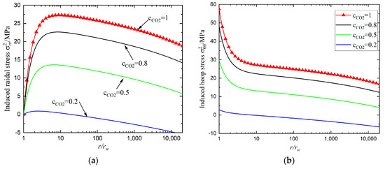
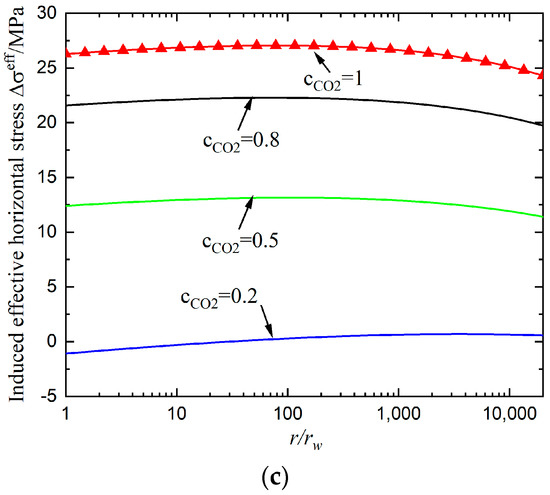
Figure 5.
Profiles of induced (a) radial stress, (b) hoop stress and (c) effective horizontal stress distribution with varying gas components. In this case, mixture gas is injected by 12 MPa with 3 MPa and ZDBC condition is imposed.
4. Wellbore Stability Analysis during Mixture Gas Injection
The developed methodology is applied to investigate the total stress field around the wellbore and coal failure with the different borehole pressures and gas components of CO2 during CO2-ECBM.
4.1. The Total Stress and Failure Index around the Borehole
The preceding investigation indicated that sorption-induced swelling has a significant impact on the stress field during mixture gas injection. In this section, the total stress distribution along with varying gas components is examined. Comparisons of Figure 6 revealed that the gas component of CO2 significantly affects the total radial and hoop stress distribution along 0° and 90° directions, whose difference is caused by initial anisotropic in-situ horizontal stress. Additionally, when the gas component of CO2 diminishes, a larger proportion of less adsorptive N2 is absorbed into the reservoir, which lowers radial stress inside the borehole and hoop stress at the borehole. In this instance, sorption-induced strain turns into net shrinkage in comparison to the initial CH4 adsorption, resulting in a reduction in sorption-induced stresses. Moreover, tensile hoop stress is generated when pure N2 () is injected into the reservoir, which leads to tensile failure near the wellbore. Similar to but different from thermal fracturing caused by temperature change [30], tensile failure is induced by the displacement of the initial CH4 with weakly adsorptive N2. Tensile failure, which was rarely noticed, should be carefully examined in the mixture gas injection with a large proportion of N2 (including pure N2) into the coal seams.
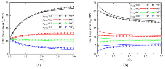
Figure 6.
Profiles of (a) total radial stress and (b) total hoop stress with radius with along 0° and 90° direction. In this case, mixture gas is injected by 12 MPa with 3 MPa and ZDBC condition is imposed.
Next, failure index around the borehole in Equation (23) with various gas components of CO2 is presented in Figure 7. Given the large gas component of CO2 (), wellbore failure due to significant sorption-induced stress (seen in Figure 6) emerges at the borehole wall. The maximum and minimum principal stresses at the borehole wall in this case are the hoop and radial stresses (i.e.,), respectively. Furthermore, since the magnitude of isotropic stress induced by sorption is substantially greater than that of initial in-situ stress, the failure index distribution exhibits negligible anisotropy. Additionally, when , the failure index around the wellbore lies in the range of −3.1~−6.7 MPa, indicating a stable wellbore state under the given conditions. Additionally, the highest failure index is located at the borehole wall in a 0° direction. In contrast, when drops further (), wellbore failure occurs at the borehole wall in the 90° direction. In this instance, a large proportion of weakly adsorptive N2 induces the smallest hoop stress at the borehole in a 90° direction, as shown in Figure 6b, which is the minimum principal stress (i.e., ). So the wellbore failure index first declines and then climbs as goes from 1 to 0.1. Then, we may deduce that for the provided parameters in this situation, the gas component of CO2 must fall within a rational scope in order to preserve wellbore stability.
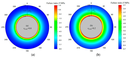
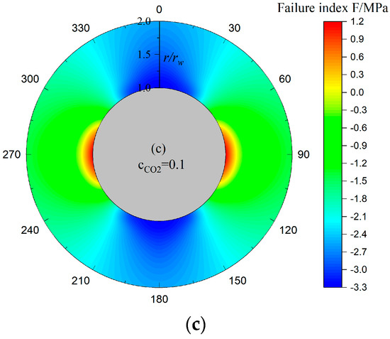
Figure 7.
Failure index distribution in the vicinity of the borehole with different gas component: (a) ; (b) ; (c) . In this case, mixture gas is injected by 12 MPa with 3 MPa and ZDBC condition is imposed.
Figure 8 depicts the evolution of the maximum failure index with borehole pressure under the varying gas components of CO2 to investigate wellbore stability in the mixture gas injection. It should be mentioned that the maximum borehole pressure is constrained to the initial minimum horizontal stress to prevent the reservoir from hydraulic fracturing. In the absence of sorption, as borehole pressure rises, the maximum failure index first sightly decreases and subsequently increases, as illustrated by the violet dashed line in Figure 8. The increase in pore pressure causes effective horizontal and vertical stresses to decline, which leads Mohr’s circle of stress to continuously shift to the left and approach the failure envelope, leading to an increase in wellbore failure index. In addition, the evolution of the maximum failure index is irrelevant with gas component , when just the poroelastic effect is taken into account.
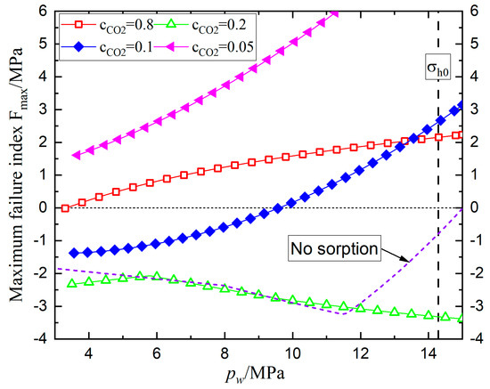
Figure 8.
Profile of maximum failure index’s evolution with varying borehole pressure and gas component. In this case, 3 MPa.
However, the maximum failure index’s evolution with mixture gas injection considering sorption-induced swelling differs from that when only the poroelastic effect is considered. Increased borehole pressure causes to decline when the gas component of CO2 reduces from 0.8 to 0.2, indicating that the wellbore turns to be stable in the mixture gas injection. Additionally, for the given specific conditions, when is higher than 0.8, mixture gas injection induces wellbore instability with arbitrary borehole pressure (certainly higher than the reservoir pressure before injection ).
In contrast, increases as borehole pressure rises when the gas component of CO2 continuously decreases form 0.2 to 0.05. As seen in Figure 6b, net shrinkage and correspondingly lower hoop stress are caused by a considerably smaller fraction of CO2 associated with a higher proportion of N2. Thus, the anisotropy of the principal stress state () continues to be magnified, and the related failure index increases, as shown in Figure 8. Furthermore, it should be noted that a large proportion of N2 () causes tensile hoop stress in Figure 6b, which also sets a lower limit of for preventing wellbore tensile failure.
4.2. Critical Borehole Pressure and Gas Component (CBPGC)
A workflow with an iterative loop was developed to obtain the critical borehole pressure and gas component of CO2 (CBPGC), maintaining wellbore stability during CO2-ECBM. CBPGC with pore pressure before injection 3 MPa is displayed in Figure 9. The upper limit of is constrained by prohibiting hydraulic fracturing in the coal seams, which is approximately equal to . Meanwhile, the lower limit of is constrained by . Additionally, the wellbore failure index restricts the upper and lower limits of the gas component of CO2.
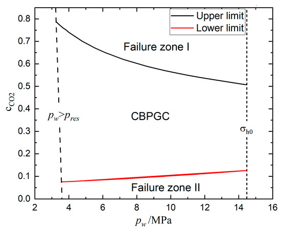
Figure 9.
CBPGC with pore pressure before injection 3 MPa. The critical in the CBPGC is confined by and , and the upper and lower limit of in the CBPGC is obtained by wellbore failure index .
Additionally, wellbore state moves into Failure Zone I in Figure 9, if a mixture gas with a large proportion of CO2 that exceeds the upper limit is injected. In this instance, as shown in Figure 6b, the displacement of initial CH4 with strongly adsorptive CO2 results in considerable compressive hoop stress, and then wellbore failure occurs near the borehole. By contrast, the wellbore state enters Failure Zone II if a mixture gas with a large proportion of N2 (the corresponding gas component of CO2 lower than the lower limit) is injected. Wellbore shear or tensile failure occurs when the initial CH4 is mainly displaced by weakly adsorptive N2, which induces lower compressive and sometimes even negative hoop stress. Therefore, the borehole pressure and gas component of CO2 should be set within the CBPGC to prevent wellbore instability. Finally, the CBPGC can provide a benchmark for in-situ coal seams’ CO2 storage capacity in terms of wellbore stability.
5. Conclusions and Suggestions
Assuming steady reservoir pressure distribution and ZDBC (zero displacement at the outer boundary) condition, the stress field taking into account the sorption and poroelastic effect is derived in the coal seams with anisotropic in-situ stress state. Then, the critical borehole pressure and gas component (CBPGC) maintaining wellbore stability is obtained by combining with shear and tensile failure criteria. Due to the distinct sorption characteristics of CH4, CO2, and N2, mixture gas injection with variable gas composition results in diverse stress change, as opposed to the case when only the poroelastic effect is considered. The following findings can be obtained from this study:
(1) The stress field is significantly influenced by the boundary condition and sorption-induced swelling characteristics. The ZDBC condition results in larger stress change in comparison to the constant stress condition at the outer boundary. Furthermore, the sorption-induced swelling of pure CO2 relative to CH4 induces compressive radial and hoop stresses, whereas tensile radial and hoop stresses are caused when only the poroelastic effect is considered;
(2) With the exception of the reservoir pressure distribution, mechanical properties and adsorption parameters both influence sorption-induced stresses. The larger sorption-induced stresses are caused by an increase in the Young modulus and Poisson ratio, which suggests that this effect should be taken into account more in the coal and shale with the high Young modulus and Poisson ratio. In addition, adsorption parameters also directly influence sorption-induced stress. More considerable sorption-induced stresses are induced by the larger and smaller ;
(3) The borehole pressure and gas component of CO2 should be restrained by the CBPGC to prevent wellbore from shear and tensile failure. Mixture gas injection with a large proportion of CO2 would result in considerable sorption-induced hoop stress and wellbore shear failure. By contrast, when mixture gas with a small proportion of CO2 is injected, the displacement of the initial CH4 with weakly adsorptive N2 would induce less compressive and even tensile hoop stress. In this instance, wellbore shear or tensile failure occurs, which is rarely noticed. Therefore, in light of wellbore stability, the CBPGC can provide a benchmark for in-situ coal seams’ CO2 storage capacity;
This paper derives a semi-analytical solution of stress field and failure index assuming the steady reservoir pressure distribution that occurs after the unsteady seepage stage. So the CBPGC can be treated as an ultimate result of mixture gas injection, and gives the upper and lower limits of CO2 storage capacity bound by wellbore stability. In addition, the injection scheme design should pay more attention to wellbore stability during unsteady seepage stage. Moreover, as cased, cemented wellbore are frequently constructed to maintain wellbore stability/integrity; interface failure and zone isolation should be thoroughly studied in the future.
Author Contributions
Conceptualization, H.X. and W.L.; methodology, W.L.; validation, Z.W. and S.Y.; formal analysis and investigation, Z.W.; resources, S.Y. and P.T.; writing—original draft preparation, H.X.; writing—review and editing, W.L.; supervision, W.L.; funding acquisition, W.L. All authors have read and agreed to the published version of the manuscript.
Funding
This research was financially supported by the Fundamental Research Program of Shanxi Province, China (Grant No. 20210302124664, 202103021224059), CNPC Science and Technology Project (Grant No. 2021DQ03-37).
Institutional Review Board Statement
Not applicable.
Informed Consent Statement
Not applicable.
Data Availability Statement
Data are contained in the article.
Conflicts of Interest
The authors declare no conflict of interest.
Nomenclature
| i | Gas type |
| Volumetric strain due to adsorption and deformation | |
| Langmuir-type swelling constants | |
| Langmuir-type adsorption constants | |
| Young modulus and Poisson ratio | |
| Kronecker’s delta | |
| Biot coefficient | |
| Initial and depleted reservoir pressure, respectively | |
| Borehole pressure | |
| Directional index in cylindrical coordinates | |
| Radius of wellbore and outer boundary | |
| Initial maximum, minimum horizontal, and vertical stress, respectively | |
| Normal and shear stress components due to in-situ stress and borehole pressure | |
| Radial and hoop stress due to poroelastic response and gas adsorption, respectively | |
| Total stress components, respectively | |
| Total stress components at the wellbore | |
| Incremental reservoir pressure and volumetric strain, respectively | |
| Integration constants | |
| Integration constants related to poroelastic response and sorption effect, respectively | |
| Wellbore failure index | |
| Rock cohesion and friction angle | |
| Maximum, median, and minimum stress, respectively | |
| Octahedral shear stress | |
| Mogi–Coulomb coefficients | |
| Gas component of CO2 and N2, respectively | |
| CBPGC | Critical borehole pressure and gas component of CO2 |
| ZDBC | Zero displacement condition at outer boundary |
| ZSBC | Constant stress condition at outer boundary |
References
- De-Silva, P.N.K.; Ranjith, P.G.; Choi, S.K. A study of methodologies for CO2 storage capacity estimation of coal. Fuel 2012, 91, 1–15. [Google Scholar] [CrossRef]
- Masoudian, M.S.; Airey, D.W.; El-Zein, A. A chemo-poro-mechanical model for sequestration of carbon dioxide in coalbeds. Geotechnique 2013, 63, 235–243. [Google Scholar] [CrossRef]
- Fang, Z.; Li, X.C. A preliminary evaluation of carbon dioxide storage capacity in unmineable coalbeds in China. Acta Geotech. 2014, 9, 109–114. [Google Scholar] [CrossRef]
- Zoback, M.D.; Gorelick, S.M. To prevent earthquake triggering, pressure changes due to CO2 injection need to be limited. Proc. Natl. Acad. Sci. USA 2015, 112, E4510. [Google Scholar] [CrossRef] [PubMed]
- Palmer, I.D.; Moschovidis, Z.A.; Cameron, J.R. Coal failure and consequences for coalbed methane wells. In Proceedings of the SPE Annual Technical Conference and Exhibition, Dallas, TX, USA, 9–12 October 2005. [Google Scholar]
- Shi, J.Q.; Durucan, S. Drawdown induced changes in permeability of coalbeds: A new interpretation of the reservoir response to primary recovery. Transp. Porous Media 2004, 56, 1–16. [Google Scholar] [CrossRef]
- Shi, J.Q.; Durucan, S. Variation in horizontal stress with pore pressure depletion in coal under uniaxial strain conditions: An update on the modelling of laboratory data. Int. J. Coal Geol. 2018, 187, 94–97. [Google Scholar] [CrossRef]
- Liu, S.; Harpalani, S. Evaluation of in situ stress changes with gas depletion of coalbed methane reservoirs. J. Geophys. Res. Solid Earth 2014, 119, 6263–6276. [Google Scholar] [CrossRef]
- Liu, T.; Liu, S.; Lin, B.; Fu, X.; Zhu, C.; Yang, W.; Zhao, Y. Stress response during in-situ gas depletion and its impact on permeability and stability of CBM reservoir. Fuel 2020, 266, 117083. [Google Scholar] [CrossRef]
- Hou, X.; Liu, S.; Li, G.; Zhu, Y.; Liu, A. Quantifying and modeling of in situ stress evolutions of coal reservoirs for helium, methane, nitrogen and CO2 depletions. Rock Mech. Rock Eng. 2021, 54, 3701–3719. [Google Scholar] [CrossRef]
- Lu, M.; Connell, L. Coal failure during primary and enhanced coalbed methane production-theory and approximate analyses. Int. J. Coal Geol. 2016, 154, 275–285. [Google Scholar] [CrossRef]
- Lu, M.; Connell, L. Coal seam failure during primary/enhanced gas production: How failure develops in fields. Int. J. Coal Geol. 2019, 221, 103432. [Google Scholar] [CrossRef]
- Espinoza, D.N.; Pereira, J.M.; Vandamme, M.; Dangla, P.; Vidal-Gilbert, S. Desorption-induced shear failure of coal bed seams during gas depletion. Int. J. Coal Geol. 2015, 137, 142–151. [Google Scholar] [CrossRef]
- Huang, F.S.; Kang, Y.L.; Liu, H.; You, L.J.; Li, X.C. Critical conditions for coal wellbore failure during primary coalbed methane recovery: A case study from the San Juan Basin. Rock Mech. Rock Eng. 2019, 52, 4083–4099. [Google Scholar] [CrossRef]
- Cui, X.; Bustin, R.M.; Chikatamarla, L. Adsorption-induced coal swelling and stress: Implications for methane production and acid gas sequestration into coal seams. J. Geophys. Res. Solid Earth 2007, 112, B10202. [Google Scholar] [CrossRef]
- Reisabadi, M.Z.; Haghighi, M.; Salmachi, A.; Sayyafzadeh, M.; Khaksar, A. Analytical modelling of coal failure in coal seam gas reservoirs in different stress regimes. Int. J. Rock Mech. Min. Sci. 2020, 128, 104259. [Google Scholar] [CrossRef]
- Masoudian, M.S.; El-Zein, A.; Airey, D.W. Modelling stress and strain in coal seams during CO2 injection incorporating the rock–fluid interactions. Comput. Geotech. 2016, 76, 51–60. [Google Scholar] [CrossRef]
- Hu, C.; Wang, F.; Ai, C. A model of cement-formation interface failure length in supercritical CO2-ECBM and storage injection well considering the coal swelling effect under high pressure. J. Pet. Explor. Prod. Technol. 2019, 9, 2757–2767. [Google Scholar] [CrossRef]
- Li, Z.; Elsworth, D. Controls of CO2-N2 gas flood ratios on enhanced shale gas recovery and ultimate CO2 sequestration. J. Pet. Sci. Eng. 2019, 179, 1037–1045. [Google Scholar] [CrossRef]
- Wen, H.; Hao, J.; Ma, L.; Zheng, X.H. Experimental Study on Replacing Coal Seam CH4 with CO2 Gas. ACS Omega 2022, 7, 1395–1403. [Google Scholar] [CrossRef]
- Gong, H.R.; Wang, K.; Wang, G.D.; Yang, X.; Du, F. Underground coal seam gas displacement by injecting nitrogen: Field test and effect prediction. Fuel 2020, 306, 121646. [Google Scholar] [CrossRef]
- Liu, T.; Lin, B.Q.; Yang, W.; Zhai, C.; Liu, T. Coal permeability evolution and gas migration under non-equilibrium state. Transp. Porous Medium 2017, 118, 393–416. [Google Scholar] [CrossRef]
- Wu, Y.; Liu, J.S.; Elsworth, D. Evolution of coal permeability: Contribution of heterogenous swelling processes. Int. J. Coal Geol. 2011, 88, 152–162. [Google Scholar] [CrossRef]
- Bradley, W.B. Failure of inclined boreholes. J. Energy Resour. Technol. 1979, 101, 232–239. [Google Scholar] [CrossRef]
- Fjær, E.; Holt, R.M.; Horsrud, P.; Raaen, A.M.; Risnes, R. Petroleum Related Rock Mechanics, 2nd ed.; Elsevier: Amsterdam, The Netherlands, 2008. [Google Scholar]
- Li, Y.; Wang, J.; Wang, Z.; Pan, Z. Variation in Permeability during CO2–CH4 Displacement in Coal Seams. Part 2: Modeling and Simulation. ACS Omega 2020, 5, 18432–18440. [Google Scholar] [CrossRef] [PubMed]
- Al-Shaaibi, S.K.; Al-Ajmi, A.M.; Al-Wahaibi, Y. Three dimensional modeling for predicting sand production. J. Pet. Sci. Eng. 2013, 109, 348–363. [Google Scholar] [CrossRef]
- Detournay, E.; Cheng, H.D. Poroelastic response of a borehole in a non-hydrostatic stress field. Int. J. Rock Mech. Min. Sci. Geomech. Abstr. 1988, 25, 171–182. [Google Scholar] [CrossRef]
- Al-Ajmi, A.M.; Zimmerman, R.W. Relation between the Mogi and the Coulomb failure criteria. Int. J. Rock Mech. Min. Sci. 2005, 42, 431–439. [Google Scholar] [CrossRef]
- Yin, S. Numerical analysis of thermal fracturing in subsurface cold water injection by finite element methods. Int. J. Numer. Anal. Methods Geomech. 2013, 37, 15. [Google Scholar] [CrossRef]


Disclaimer/Publisher’s Note: The statements, opinions and data contained in all publications are solely those of the individual author(s) and contributor(s) and not of MDPI and/or the editor(s). MDPI and/or the editor(s) disclaim responsibility for any injury to people or property resulting from any ideas, methods, instructions or products referred to in the content. |
© 2023 by the authors. Licensee MDPI, Basel, Switzerland. This article is an open access article distributed under the terms and conditions of the Creative Commons Attribution (CC BY) license (https://creativecommons.org/licenses/by/4.0/).