Article

Improving the Energy Efficiency of Equipment for the Impregnation of Roof Trusses—Modeling and Practical Implementation

Faculty of Process and Environmental Engineering, Lodz University of Technology, Wolczanska 213, 90-924 Lodz, Poland
*
Authors to whom correspondence should be addressed.
Sustainability 2023, 15(5), 4261; https://doi.org/10.3390/su15054261
Submission received: 25 January 2023 / Revised: 14 February 2023 / Accepted: 22 February 2023 / Published: 27 February 2023
(This article belongs to the Section Energy Sustainability)

Abstract

:
The impregnation of elements made of wood is one of the most important stages of their maintenance and the modification of their parameters. Incorrectly prepared material is sensitive to moisture, fungi, algae or weather conditions. In the case of large wooden elements or ready-made installations, impregnation is often performed not indoors, but outdoors. Despite the obvious advantages, this solution also has a number of disadvantages. One of them is the long duration of the impregnation process, as well as the variability in the process parameters along with changing weather conditions. In addition, the final material properties may differ not only from batch to batch, but also within the batch. In order to eliminate these problems, the equipment for wood impregnation was modernized. As part of the work, models of installation elements were made, a computer simulation was performed, and the necessary design calculations were carried out. The work will be crowned with the practical implementation of the proposed solutions in test equipment and the verification of design assumptions. The effect of the modernization of the system was a significant shortening of the impregnation process, as well the ability to obtain a final product of higher quality.

1. Introduction

Despite significant advances in technology and the construction of new materials, wood remains one of the most used building materials in the world [1]. This type of material is associated with a number of advantages, both physicochemical, mechanical and economic. The most important of these advantages are its low thermal conductivity, high heat capacity, and acoustic and electrical insulation [2]. Moreover, it is a material that is mechanically relatively strong, especially considering its low density. Low density also translates into lower transport costs. An additional advantage is the ease of processing, as well as a huge variety of tree species with different properties [1].
Among the disadvantages of this material, high sensitivity to external conditions should be distinguished. While it is a material that is relatively resistant to oxidation, meaning that it can be used in corrosive environments, there are many other factors that can deteriorate its properties or even destroy it completely. We can distinguish destructive biological and non-biological factors [3]. Due to the fact that wood is a biological material, it is food for certain plant and animal organisms. Among them we distinguish fungi, molds, insects, termites, insects, as well as larger animals. This is perfectly normal because trees are a natural part of the forest ecosystem under natural conditions. For this reason, many factors break them down into prime factors, so that they finally become part of the rune. Throughout their life cycle, however, trees provide shelter, protection, or even food for other living organisms. The non-biological factors include the action of UV radiation, erosion caused by wind, moisture and mechanical damage. The dimensions of the wooden material are strongly dependent on the moisture content, so as it decreases, the material shrinks. Along with these changes, the pores inside the wood structure expand and compress, and thus microcracks appear, which is especially visible on the surface of the material. In addition, in the case of the action of biological factors, not only surface damage, but also volumetric damage, e.g., due to the development of mycelium or the release of chemical substances by living organisms, often occurs. In addition, larger organisms, such as insects, can eat away channels and larger structures in wood, which almost irreversibly destroys the wood and reduces its mechanical parameters. In the case of already installed building materials, such damaged wood is a critical breach of safety standards and should be protected as soon as possible, because in the event of a failure, it can be a huge risk [4].
For these reasons, various methods have been used for years to protect the wood surface against the above-mentioned factors. Such activities are generally called wood seasoning. In most cases, such actions are aimed at creating a barrier between the wood and the destructive factors. However, this is not always necessary. In the case of wood that is not constantly exposed to unfavorable weather conditions, chamber drying is often a sufficient preparatory process. During this process, all pests and fungal spores are eliminated. In the case of elements exposed to moisture, snow, etc., it is necessary to apply additional protection. Already in ancient Egypt, in many cases, valuable products have been preserved with the use of cedar oil, and over the years, it has also been possible to observe the use of wood tar and coal for this purpose. The current choice of wood surface protection products is much wider. You can choose between a wide range of measures, such as natural oils and synthetic oils, as well as specially prepared resin mixtures and various impregnation methods that can be applied depending on the use of the wood and your budget [5].
Among the impregnation methods, four most commonly used methods can be distinguished [6]. The first is the vacuum-pressure method, which is carried out in an apparatus called an autoclave. During this process, a negative pressure is created, as a result of which air is sucked out of the wood and the impregnant flows in its place. It is a very effective process because the impregnation agent penetrates the wood to a great depth, thanks to which the material is very well protected. The disadvantage of this technique is the need to use special equipment and impregnating agents with specific properties, e.g., substances that are too sticky will not be able to penetrate the pores in the wood. Another deep impregnation technique is the non-pressure method, also known as the immersion method. As in the case of the previously described method, the wood is immersed in the impregnation and then put aside for a longer time, depending on the desired effect; this time ranges from several dozen minutes to days. This method allows for securing the material at a greater depth, and does not require specialized equipment; it can be both pre-prepared in baths and properly prepared in pits with the ground. The disadvantage is the longer process time, as well as the creation of a product with slightly worse and less reproducible properties. In addition to the in-depth methods, there are also surface methods. Their main advantage is that they can be used not only on structural elements, but also on those that have already been installed [7]. The simplest of them is to apply the preparation manually using a sponge, roller or brush. This is a popular method for home applications such as refreshing garden furniture. Its more developed method, which can be partially automated, is spray impregnation, in which the agents are applied using pneumatic sprinklers. Both of these methods are quite simple and do not require a lot of space or complicated apparatus, but they do not work well for complicated structures with hard-to-reach places. In addition, this method, when applying the substance manually, is time-consuming and requires the use of personal protective equipment due to the possibility of spraying the toxic substance. The greatest disadvantage of surface methods is the large loss of impregnating material [8].
In the wood protection technology, it is also worth distinguishing several types of impregnating substances, because they often determine not only the properties of the finished product, but also the type of application technology chosen. In addition, such a substance must meet certain requirements closely related to the properties of wood. Due to the fact that wood is a working material, in the case of applications in which significant stresses can often occur in the material, it is not recommended to use rigid coatings, such as varnishes. Then, they could crack, which would make the applied coating not fulfil its task. The impregnants differ mainly in their chemical composition and the type of solvent used. One of the groups of impregnants is salt preparations. They are mainly used to protect construction materials from fire, insects and fungi. These are water-soluble impregnations, applied by submerged methods. They penetrate the wood very well, but require additional surface protection. This is not only because they are sensitive to water, but because they are also corrosive to metal parts. Another group is water-based impregnations. They have a similar application to salt impregnations, but they are mainly applied via surface methods. Their main advantage is high efficiency, quick drying, odorlessness and the possibility of using them even on damp wood [9]. On the other hand, they are not recommended for use on very dry or damaged wood, which may swell and create microcracks. Solvent-based impregnations that do not cause the wood to swell are a good solution for such applications. They can be applied with both deep and surface methods. In addition to protecting against pests, they also protect the wood from UV radiation. The disadvantages of these substances include their toxicity, volatility and flammability. Each group of impregnants can also contain a wide range of chemical additives. They affect the properties of the material, from its fire resistance or biocidal properties, to purely aesthetic properties such as surface texture or wood color [10].
The optimization confirmed the rightness of the use of a heat exchanger and a hydrodynamic mixer, increasing the efficiency of the roof truss impregnation process, and increasing the energy efficiency of the process. On the other hand, the use of wood post-production waste in order to increase the energy efficiency of the process and shorten the residence time of the product in the impregnation process significantly reduces the carbon footprint of the finished product and the amount of primary energy built into it. In addition, increasing the thermal inertia of the entire set through the use of a high-capacity coil reduces the risk of stopping the technological process in the event of a lack of energy or temporary interruptions in its supply; this reduces the production of defective products of lower quality or not fit for use, and thus a creates a significant reduction in the production waste.

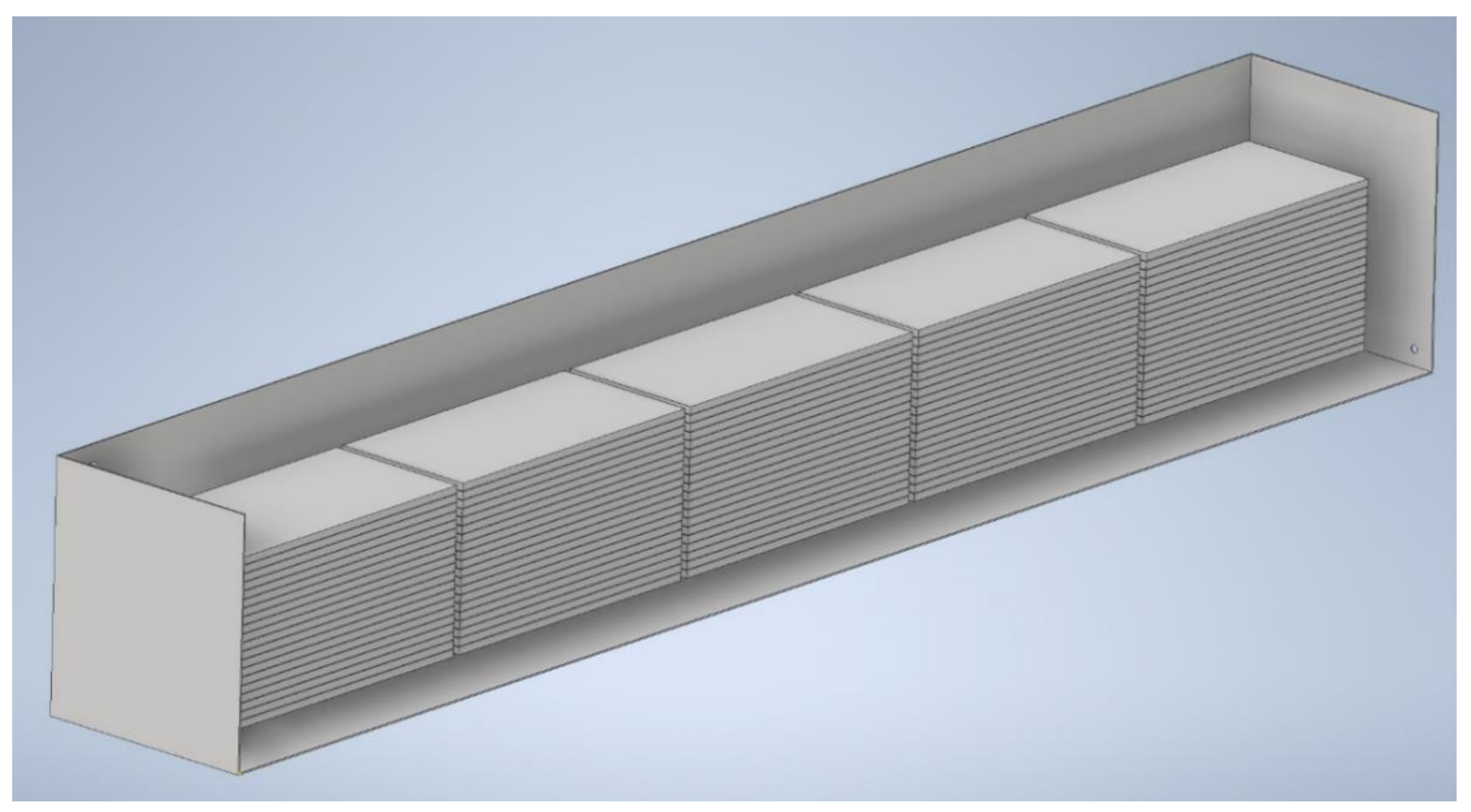
2. Material and Methods: Object of Optimization—Apparatus for Roof Trusses Impregnation

During the observation of the operation of the apparatus for immersion impregnation with the use of salt impregnation, a number of disadvantages of this solution were observed. The tested equipment was used to season the construction material for the construction of roof trusses. Due to the size of the elements and their application, the immersion method was used. It allows for high penetration of the wood through the impregnation, and it is also a relatively cheap and maintenance-free method. However, during the analysis of the final product, it was observed that the elements’ quality was not reproducible. The basis for this observation was the different degree of wood penetration not only between batches, but also within one product batch. The reason for such behavior from the material was the mass exchange mechanism; due to the lack of liquid circulation inside the bath, the mass exchange was carried out by convection, so the value of the mass transfer coefficients was relatively low. Moreover, due to the lack of liquid circulation, there was no self-renewal of the interfacial layer, and thus the concentration gradient between the liquid at the wood surface and that in the tank decreased significantly during the process.
Boundary process conditions:
  • Wood species: Siberian spruce.
  • Impregnation time in the bath: 3 h
  • Impregnate: FOBOS M4 a mixture of ammonium salts of phosphoric and sulfuric acid, boron compounds and additional organic ingredients. The combination of the developed NanoSilver 1% colloid with the currently used impregnation gives a stable and homogeneous mixture, without precipitating deposits. The concentration of silver nanoparticles in the final solution is 200 ppm; this is an amount sufficient to give aseptic properties to roof trusses impregnated with the immersion method [11].
  • Solution temperature: 32 degrees.
Another disadvantage of the chosen solution was its high sensitivity to weather conditions, especially temperature. The impregnation tanks were located outside, and it was observed that the impregnation time was significantly longer in the winter season compared to the summer season. The constant control of external conditions and the correction of process parameters was required. This could be caused by several factors, the common cause of which was a change in temperature. It translates into differences in the speed of the chemical reactions, the mobility of particles, the viscosity of the liquid or the pore size in the wood. In order to verify the findings regarding identification, a decision was made to modernize the impregnation bath. Due to the costs and size of the device, it was assumed that before the practical implementation of the equipment, a CAD model would be made, as shown on Figure 1, and on its basis, a series of calculations and simulations would be carried out.
The main element of the existing test stand was a wood impregnation tub made of high-quality carbon steel. Due to the aggressive chemical medium inside the whirlpool tub, its interior walls were protected with an internal coating made of a double layer of specialist epoxy paints with a hardener (a two-component epoxy primer/high solids intercoat containing zinc phosphate), and an exterior coating using a single layer of the above-mentioned covering. Its internal dimensions were 10.47 × 1.47 × 1.51 m. At a height of about 0.150 m from the bottom, there was a movable metal scaffolding made of eight I-sections and two C-sections, on which the wooden elements of the roof trusses to be treated were placed. The scaffolding moved vertically, which allowed the loading and unloading of wood using a forklift. Due to the desire to ensure the trouble-free operation of the system, it was decided that the heating element would be placed between the bottom of the tank and the aforementioned scaffolding. This would allow the process to avoid mechanical damage to the apparatus in case of the improper placement of the load in the bathtub. Moreover, it would also allow the spontaneous thermal convection to intensify in the tank, especially in the initial phase of heating the liquid.
Packages of wooden elements of several possible dimensions were placed on the scaffolding: 45 × 95, 45 × 120, 45 × 145, 45 × 170, 45 × 195, 45 × 220, 60 × 95, 60 × 120, 60 × 145, 60 × 170, 60 × 195, 60 × 245 cm. Successive layers of truss elements were separated by wooden spacers with a thickness of 5 mm, as shown on Figure 2, which enabled the circulation of the impregnation mixture between the trusses and the even course of the process. Thanks to this, the highest possible quality of the final product was guaranteed. The maximum size of the package that could be placed in the bathtub was 10.0 × 1.2 × 1.0 m. Dry wood has a lower density than the impregnation solution, so it was pressed down before loading using a hydraulically powered metal platform which, for safety reasons, remained on the load throughout the process.
An additional limitation of the system geometry was the necessity to take into account the fact that the truss elements must be removed and put into the bathtub between the process cycles. This made it necessary to make the equipment of the materials with an appropriate mechanical strength, so that they did not get damaged in the event of an unplanned impact during loading. Due to the fact that the device was open and the impregnated wood could leave dirt, the installed equipment had to not interfere with the simple cleaning of the bathtub, particularly of its bottom. In addition, the piping system had to be suitable for internal cleaning in at least two ways: high pressure liquid in the case of periodic cleaning, and cleaning with a ramrod in the event of an emergency blockage of the system by debris.
The bathtub was filled with FOBOS M-4 impregnation mixture. This is a mixture of ammonium salts of phosphoric and sulfuric acid, boron compounds and organic additives. It contains coating substances that protect the wood against the effects of temperature, fire, fungi, mold and insects. Due to its chemical composition, this mixture is chemically active and corrosive. This was taken into account in the selection of materials from which the apparatus would be made. When selecting materials, weldability was also be taken into account [11].
The aim of the research was to conduct a mathematical and simulation analysis in order to justify and optimize the operating parameters of the improvements, i.e., a heat exchanger and a stirrer with accessories, understood as a process innovation in the field of the impregnation of the wooden elements that form roof trusses. Ultimately, the installation was to test the impact of increased temperature and forced convection inside the bathtub on the course of the process, as well as the intensification and optimization of the wood parameter modification process. The aim of the research was, in particular, as follows: a reduction in the impregnation time, an increase in the “processing capacity” of the impregnation tank, the management of the production waste and the maintenance of the repeatability of the final product, regardless of weather conditions.
During the research work, a number of mathematical tools and computer software applications were used. During the preliminary analysis of the applied technological solutions, a strength analysis of the materials and an analysis of the mass and heat transfer, a mathematical analysis supported by theoretical apparatus and a calculation path typical for a given field of engineering were used. PTC MathCad and Matlab software were used during the calculations. Three-dimensional models and detailed drawings of apparatus elements were made using Autodesk Inventor, Autodesk AutoCAD and the Solidworks package, Mesh generated for mass transfer simulation. The number of simulation elements exceeds 500,000, and the number of nodes—1,000,000. When performing CFD simulations, both the Solidworks package and additional calculation packages, such as Solidworks Flow Simulation, as well as ANSYS Workbench and ANSYS Fluent software were used.

3. Results

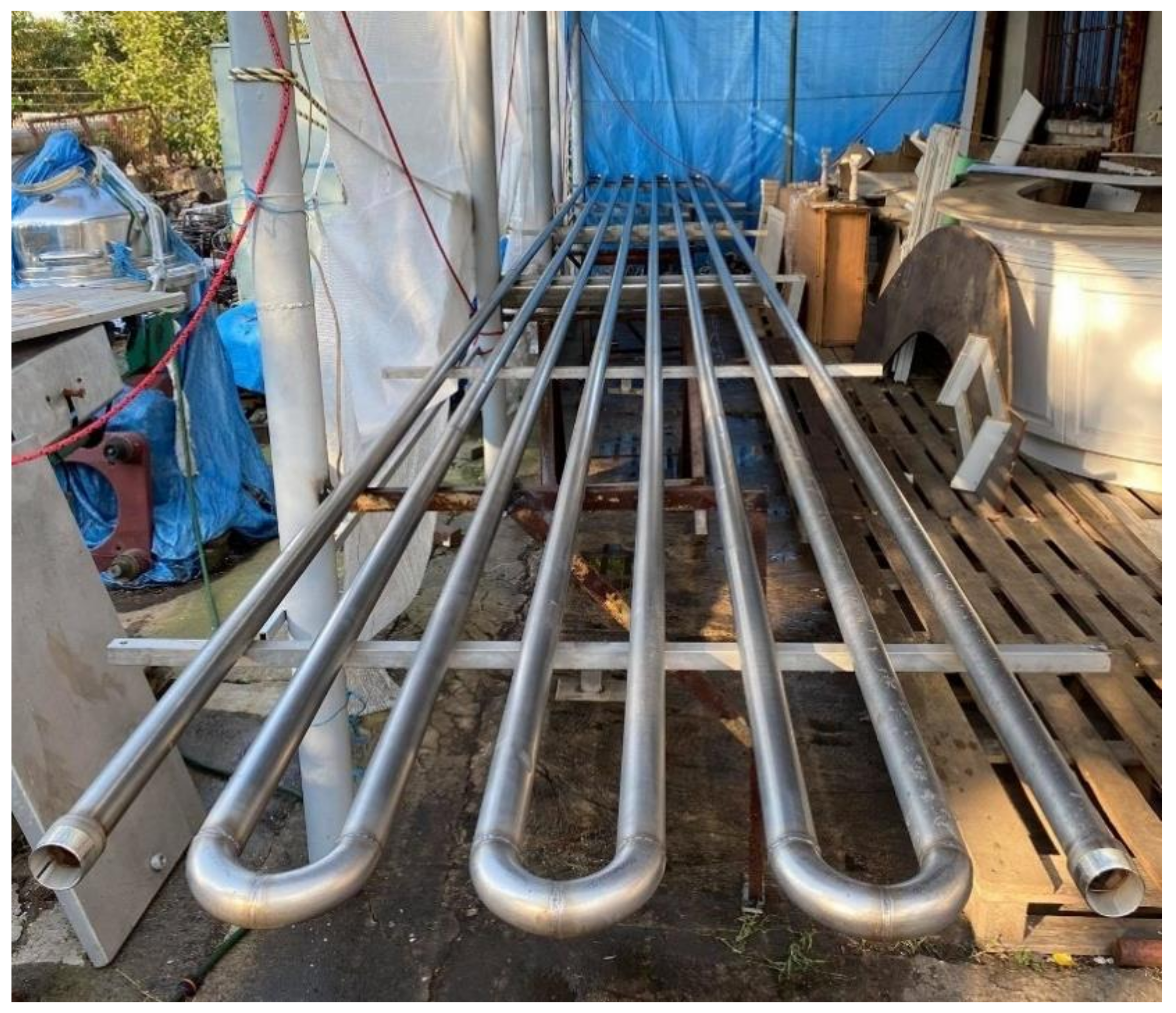
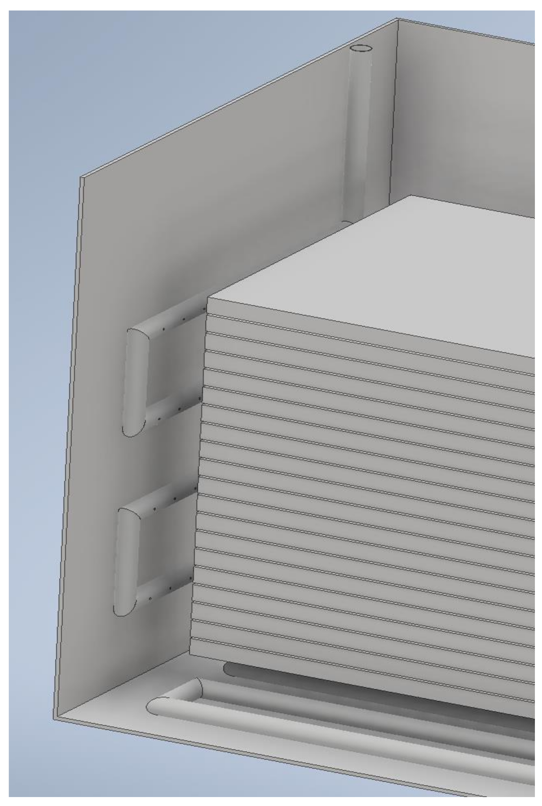
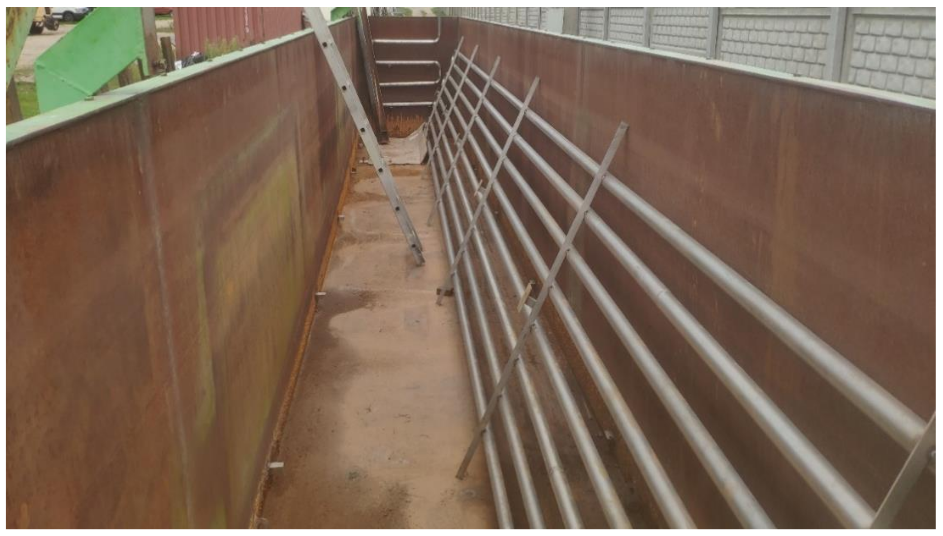
3.1. Heat Exchanger Selection

In its present form, the wood impregnation process takes place at an ambient temperature. The load is immersed in the impregnation solution and remains there until the desired end parameters are achieved. Due to the fact that some of the bathtubs were located outside the building, it was not possible to use them when the ambient temperature was negative. For this reason, it was decided that a heating element in the apparatus Would be installed. Due to the limited space for the heating element, it was decided that a flat tube exchanger in the form of a coil Would be installed. The exchanger structure was based on 8 parallel pipes, 992 cm long, connected with each other by means of straight elbows. The solution assuming the connection of the inlet and outlet of the coil using more than one route (a typical solution for tubular ground heat exchangers) was not decided, because it would not allow for forcing an even circulation of the heating liquid through the entire volume of the exchanger. The chosen solution also guaranteed the elimination of the so-called “dead zones” of the coil, i.e., places where the minimum or no liquid flow is observed. Subsequent pipes in the exchanger were spaced 100 mm apart, which resulted, among others, from the limitations of the assumed technique of the exchanger assembly. It was assumed that the individual pipes in the exchangers would be joined using welds, which was to ensure the highest possible strength and tightness at the lowest possible cost. A greater distance between the tubes would require additional pipeline sections and welds to be placed between the elbows, which would adversely affect the strength of the system and would have the slight benefit of a negligible increase in the heat transfer surface. Increasing this geometry would also not ensure the formation of the flow inside the pipe, which translated into an unnecessary increase in the flow resistance. The proposed geometry of the system allowed for trouble-free cleaning of the exchanger both before and after its emptying. The chosen width of the slot allowed the use of mechanical (brooms, scrapers, etc.) and pneumatic means.
When calculating the exchanger, it was assumed that the number of tubes in the exchanger should be even. Thanks to this, you could easily place the inlet and outlet nozzles on the same wall of the bathtub, which would significantly reduce the number of fittings connecting the exchanger to the heating boiler. This translates into lower heat losses and flow resistance. During the calculations and simulations, it was decided that the optimal number of pipes in the designed exchanger would be eight. This amount would allow the maximization of the ratio of the heat exchange surface to the flow resistance inside the exchanger and possibly even ensure the heating of the liquid in the bath; this would positively affect the quality and repeatability of the prepared product.
The outer diameter of the tubes of then the exchanger was 50 mm. In the course of the performed calculations, it was concluded that this value was the optimal compromise between the strength requirements, low flow resistance, high heat transfer area and the material cost of the installation. This value, together with the proposed mounting height, ensured that the natural circulation of the hot liquid at the bottom of the bathtub was forced. The relatively high diameter also allowed the mechanical cleaning of the inside of the pipe. When selecting the dimensions of the pipe according to the PN-EN 10296-1 [12] standard, it was decided that 1.6 mm thick walls would be used. Due to the appropriate design of the heating element and the presence of the scaffolding on which the trusses were located, the exchanger did not transfer significant mechanical loads during the normal operation of the device (apart from the mass of hot liquid inside the heating element and the mass of liquid filling the bathtub). High loads that can damage components appear only during emergency scenarios, when, for example, pallets with trusses are incorrectly placed in the device or one of the trusses falls to the bottom of the device. For this reason, it was decided a relatively low wall thickness for the pipeline would be used, which ensures safe strength and a lower thermal resistance R (by 25% compared to the popular 50 × 2 mm pipes) [13]. The total external area, which was the same as the heat transfer area, was 12.811 m2. The total length of the exchanger presented on Figure 3 was 88.559 m. Compared to other geometry variants, the ratio of the heat exchange surface to its length was high, which means that there was a low flow resistance with as much heat released as possible.
The properties of the medicinal product of the impregnation process differed noticeably in the scope of their application before and after the implementation of changes. In order to determine them, it was decided that the impregnated boards obtained for testing would be developed. After the impregnation process, the wooden elements were dried and then cut perpendicularly to their length into pieces 10 cm thick. Then, the wooden elements were compared and the thickness of the layer was measured, in which changes characteristic of the impregnation were introduced. Thanks to this, it was possible to collect the results of the process based on several visual observations:
efficiency of the impregnation process based on the depth of penetration of the impregnation agent in wooden elements,
evenness of impregnation on all walls of the board and between cross-sections on its different sections,
repeatability of the process checked by the appearance of the cross-sections of the boards in different parts of the tub within one part of the product, and also next to other parts,
uniformity of the diameter of the impregnating agent, which was manifested by anomalies or higher deviations from the average penetration depth of the impregnating agent.

3.2. Selection of Elements Forcing Fluid Flow

In standard tubs, the conventional system, in which the processed elements are immersed in a stationary liquid and remain in it until its final parameters are reached, is very ineffective. The lack of liquid movement inside the tank has many negative consequences. The concentration of the impregnation solution can vary significantly throughout the volume of the tank, which can lead to poor product quality reproducibility. The lack of forced convection means much lower coefficients of mass transfer between the solution and the wood, which significantly extends the process time.
In the initial phase, it was assumed that the liquid would be forced inside the tub by means of a mechanical agitator or a system of smaller mechanical or self-priming agitators. This concept was abandoned due to the very limited space between the tub wall and the load. In the variant with the largest tub filling, the distance between the load and the walls of the tub was less than 20 cm. While it would be possible to select a mixer whose rotor would fit in this gap, it would be impossible to install the motor inside the tub. Its installation would require drilling a hole in the wall of the tub, as well as sealing the motor shaft. Due to the aggressive medium inside the bath, using rubber and silicone seals was not advisable, and graphite seals are expensive and sensitive to mechanical damage.
The vertical agitators also fell short of expectations during the field tests. In the standard configuration, they do not ensure that the liquid is forced between the successive layers of the trusses, because they create a radial flow, not an axial one. In the case of changing the orientation of the rotor axis in parallel to the wall of the wood load, the radius of this type of mixer is too low to ensure a uniform liquid movement between all the layers of the processed wood. The use of batteries for this type of agitator would be too costly both in installation and operation.
Blending by bubbling with air-entraining diffusers also fell short of the project’s objectives. When installed on the bottom of the tank, it would allow the liquid to move in the entire volume of the bath, but the generated air bubbles could cause the liquid to splash. Taking into account the chemical properties of the liquid filling the bathtub, such a solution was unacceptable due to the need to ensure safety on the premises of the plant.
Finally, it was decided that a flow agitator would be designed. Here, the liquid is sucked in by a nozzle at one end of the tank, compressed by a high pressure pump, and then released through a set of nozzles at the other end of the tank. The nozzles are spaced, as presented on Figure 4, so that the liquid is evenly pushed inside the truss load. An additional advantage of this solution is the lack of any moving parts inside the bathtub. This minimizes the number of components that can fail, and the use of a two-pump system (working and replacement) allows you to avoid downtime during system operation.
The principle of operation of this type of apparatus is similar to the operation of aerators. Pressurized liquid is fed through nozzles and then it moves through the bed. Due to the even distribution of the holes and the high flow velocity, the liquid can move through the wood bed and there is no intensive bypass phenomenon. In addition, the moving liquid causes the movement of the liquid already in the tank, thanks to which vortices are created, and thus the movement of the liquid shows the characteristics of turbulent movement. As a result, an improvement in the value of the mass transfer coefficients can be assumed. The role of the set of nozzles is performed by a four-row coil with 10 holes drilled in each row. The diameter of the holes varies between the rows; in the first row it is 5 mm, and in the other rows it is 6 mm. The total height of the element in the bathtub is 1275 mm. The distance between the axes of the pipes is 250 mm. The holes in the coil are 95 mm apart. The geometry of the nozzle assembly ensures that the liquid moves evenly in front of the load, and the diameter of the openings ensures the high pressure of the liquid exiting the nozzle. As a result, the high penetration of the load of the trusses is possible and the phenomenon in which the moving liquid largely misses the load due to the higher flow resistance in the channels between the wood is avoided. The diameter of the holes should not be lower than the assumed values due to the risk of blockage by solid contaminants during standstill, breakdown or maintenance. During the operation, the probability of clogging the nozzles is very low due to the high pressure and the presence of filters in the supply line. The end of the coil is sealed with a threaded plug. This allows the periodic mechanical cleaning of the inside of the nozzle assembly using a brush.
There is a suction piece at the other end of the tank. It is an open tube that is 50 mm in diameter with an end-mounted suction strainer and with an outer diameter of 340 mm. The suction strainer is made of 2 mm thick perforated stainless steel. The mesh size is 5 mm and the distance between the meshes is 4 mm. The sheet clearance is 23%, and the height of the dragon is 90 mm. The suction strainer avoids permanent damage in the form of being sucked into the pump and damaged. High clearance allows the minimization of local flow resistance while maintaining the high filtering capacity for contaminants. All elements of the apparatus before installation in the tank are presented on Figure 5.

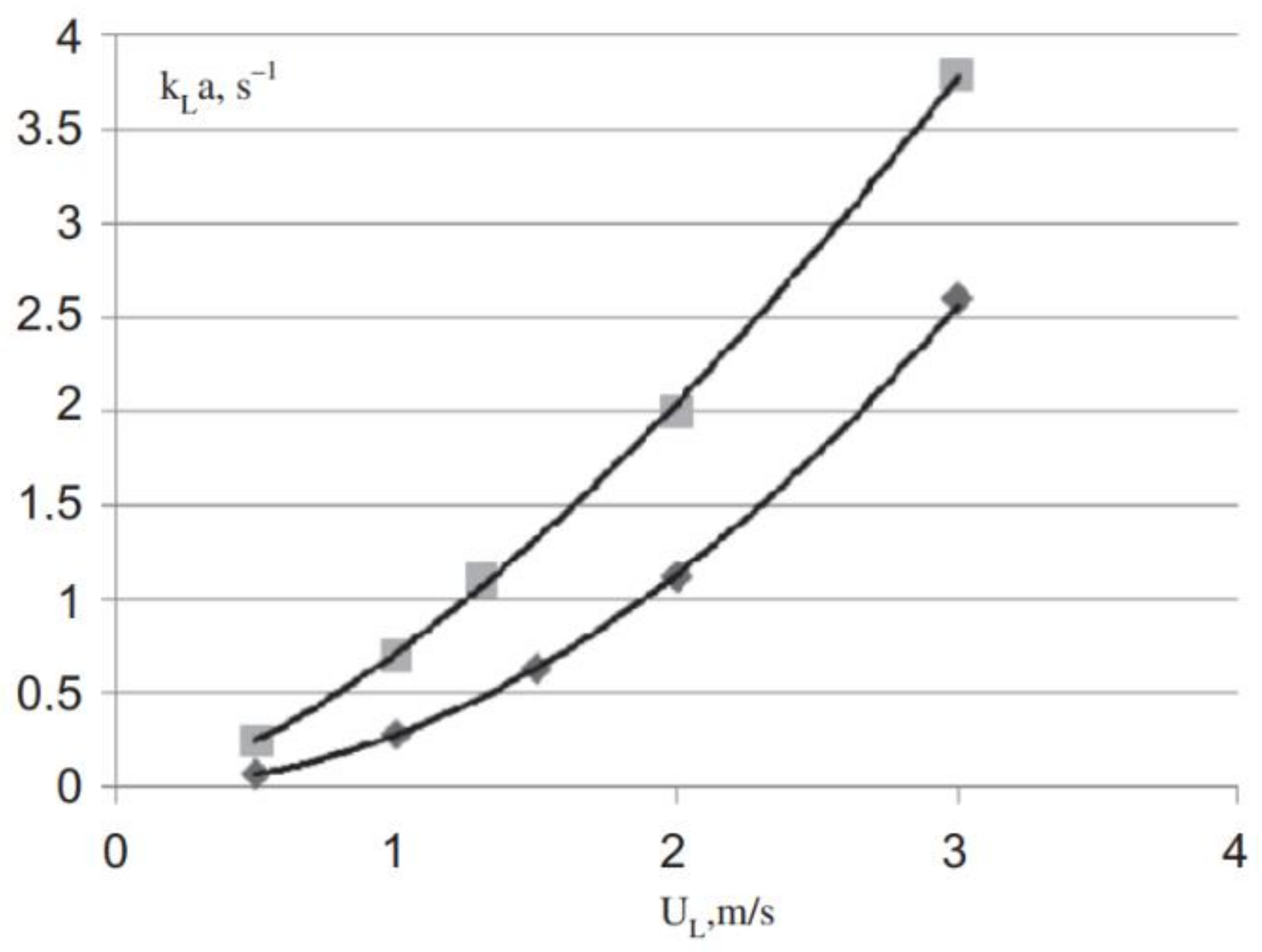
3.3. Influence of the Changes Made on the Mass Transfer

The primary mechanism of mass transfer in a fluid is diffusion. It is based on the spontaneous spreading and penetration of particles in the medium, which is caused by the chaotic collisions of particles diffusing between themselves and the particles of the medium. The basic laws that can be used to describe the diffusion process are Fick’s laws. The first is that the diffusion flux is directly proportional to the negative concentration gradient. This process is analogous to the heat transfer process [14]. In a three-dimensional coordinate system, the equation describing this process is as follows:
N i = D i c i ,
where
  • Ni—component flux density i mol m 2 × s ,
  • Di—component diffusion coefficient i m 2 s ,
  • ci—component concentration i mol m 3 .
Thus, the main one describing the mass transfer in a given medium is the diffusion coefficient. Its value is proportional to the speed of diffusing molecules. It is a function of numerous system parameters, such as temperature, the structure of the medium or fluid viscosity. In the case of viscous fluids, e.g., in a test solution, the behavior of diffusing molecules is described by the Stokes–Einstein law, which has the following form:
D = k × T 6 × π × μ × r ,  
where
  • k—Boltzmann constant,
  • T—temperature [K],
  • µ—dynamic viscosity of the fluid [Pa × s],
  • r—radius of the diffusing particle [m].
The given form of the equation implies some simplifications (including those resulting from the assumption that the particles of a fluid obey the Stokes law); however, it allows the drawing of certain conclusions regarding the solution proposed in the project [15]. An important observation is the strong relationship between the values of the diffusion coefficient and temperature. It is impossible or negligible to change the value of the D coefficient by manipulating the remaining parameters. However, the relationship D = f (T) is not linear, not least because the viscosity of the fluid is also strongly temperature dependent. Therefore, the above equation can be represented as follows:
D T 1 D T 2 = T 1 T 2 × μ T 2 μ T 1
Therefore, to demonstrate the relationship between the diffusivity coefficient and temperature, the Arrhenius equation should be used:
D = D 0 × exp E diff R × T ,
where
  • D0—diffusion proportionality coefficient,
  • R—gas constant J mol × K ,
  • Ediff—diffusion activation energy.
This equation can be transformed to a linear form, as follows:
lnD = lnD o E diff R × 1 T
On this basis, it can be concluded that the value of the diffusion coefficient increases with increasing temperature. The exact values of the coefficients, as well as the equation of this dependence, will be possible to find after the experimental testing of the values of the diffusion coefficient for different temperatures. On the basis of the above considerations, however, it can be clearly stated that the temperature increase in the systems will have a very positive effect on the course of the mass exchange process, and should also shorten the time required to obtain the assumed results.
It is worth noting, however, that in the case of the tested system, the actual value of the mass transfer coefficient will be lower than it would appear from the above considerations. It results, inter alia, from the fact that the treated object is a porous medium [16]. This means that part of the interface may not be involved in the mass transfer process (the pore size may be small so that diffused molecules get into it). In the case of the remaining pores, the efficiency of the process is also limited; in smaller pores, due to the proximity of particles and walls, the dynamic viscosity is much higher, which results in a lower diffusion coefficient. In addition, for larger pores, the path that the particles must travel is longer due to the tortuosity of the pores. For this reason, it is recommended that a modified equation for porous bodies is used:
D e = D × ε t × δ τ ,
where:
  • De—diffusion coefficient in porous bodies,
  • ε t —material porosity (including zones excluded from the mass exchange process) [-],
  • δ—coefficient depending on the ratio of the size of the diffusing particles to the pore diameter [-],
  • τ—the tortuosity factor of the pore channels [-].
In the case of the processed material, however, it is worth paying attention to the additional effect related to temperature. The increase in temperature, apart from increasing the value of the diffusion coefficient, also intensifies the additional process taking place in the wood immersed in an aqueous solution. This process is swelling, i.e., the process of increasing the linear dimensions and volume of wood as a result of the absorption of water vapor or water from the environment and its penetration into the pores of the cell membrane [17]. This phenomenon causes a significant increase in the size of the pores of the solid, and thus reduces the diffusion resistance (by increasing the value of the coefficient δ), and also reduces the number of pores too small for diffusion (i.e., the surface area of the interfacial surface suitable for the mass exchange process is increased). The wood brewing process is widely used in industry. It has been confirmed in the industry literature that increasing the temperature above 40 °C allows for a significant intensification of the wood-swelling process [18].
An additional effect resulting from the conducted research is the intensification of liquid movement within the interface between the treated trusses. The forced convection of the liquid leads to a continuous renewal of the liquid layer, which has a positive effect on the course of the process. This unifies the concentration prevailing in the entire bath, thanks to which the modification of wood parameters should be much more uniform, and the quality of the final product should be more reproducible. Additionally, due to mixing, the concentration of the diffusible substance is higher than in the case of the process without mixing. This is due to the higher concentration value right next to the wood walls and, consequently, the higher pressure gradient. According to Fick’s first law presented above, a higher gradient translates into a higher flux of diffusible substance.
Another factor indicating the positive impact of the proposed changes on the course of the process is the fact that a higher temperature and mixing intensify two successive unit processes. Apart from structural substances such as cellulose, lignin or hemicelluloses, wood also contains non-structural and extractive substances. When wood is immersed in a liquid, these substances are released into the solution. Their examples may be, among others, hydrocarbons (including monoterpenes), fatty acids, alcohols, esters, and aromatic hydrocarbons [19]. Their presence in wood significantly affects its final physicochemical properties. An increased temperature and mixing significantly accelerate this process due to the above-described continuous renewal of the interfacial layer, an increase in the concentration gradient and an increase in the solubility of these substances with increasing temperature. As a result, the wood achieves the desired parameters faster. The second phenomenon related to the substances described is the possibility of a chemical reaction between them and the substances in the solution. According to Van ’t Hoff’s rule, in homogeneous single-phase reactions, the temperature coefficient increases with an increasing temperature [20]:
Q = 1 + Δ T k T ,
where
  • Q—reaction temperature coefficient,
  • kT—reaction rate constant at temperature T,
  • Δ T —change in temperature.
The relationship between the rate of a chemical reaction and the temperature in a larger temperature range is described by the Arrhenius equation:
k = A × exp E a R × T ,
where
  • k—reaction rate constant [-],
  • A—constant A/particle collision frequency factor [-],
  • Ea—reaction activation energy J mol × K .
In the case under study, two parameters directly affect the length of the process: the value of the mass transfer resistance on the surface of the material (convection coefficient) and its volume (diffusion coefficient). In the case of both these parameters, their value during impregnation varies with time due to the constantly changing properties of the wood. Along with the course of the process, the moisture content in the trusses increases, which results in a significant decrease in the values of the aforementioned coefficients, mainly due to the saturation of the wood at a given distance from the surface [21]. However, experimental data show a clear effect of increasing the temperature on the mass transfer process, as shown in Table 1. The value of the surface mass transfer coefficient is directly proportional to the value of the surface mass emission coefficient [22].
Depending on the treated type of wood and its moisture content (which changes with time and distance from the surface), an increase in the efficiency of the mass exchange process can be expected, and thus a reduction in the process time by 50–150% as a result of only increasing the process temperature by 20 °C. In the case of the analyzed process, the effect will be even greater due to the increase in the reaction temperature by at least 25 degrees, and in extreme cases, even by 40. A similar increase can be observed in the case of mass exchange inside the wood, but in this case, it is impossible to provide exact numerical values due to their high uniqueness; the structure of the wood changes between successive repetitions of the experiment, between different types of wood, and even between samples of the same tree (e.g., due to different arrangement of the rings).
Another factor directly influencing the increase in mass intensity is the aforementioned increase in the turbulence of the liquid flow in the bathtub. The effect of such an operation on the duration of the process can be assessed on the basis of the data relating to the mass transfer in the liquid–solid system with the use of mixers with different geometries and rotational speeds. The flow agitator is not widely used and without experimental data, it is not possible to accurately determine its influence on the liquid flow; however, the high velocity of the fluid leaving the nozzles (at least 2 m per second) and the high surface coverage allows a comparable performance to the high-surface turbine mixers to be assumed [23]. The graph presented in Figure 6 shows the influence of the mixing speed on the value of the mass transfer coefficients in the analogous liquid–solid system for two different types of turbine mixers. The upper graph shows the results for the solid lug agitator, and the second one shows the results for the orifice foot agitator.
In the case of the analyzed process, the first diagram is more appropriate due to the characteristics of the stirrer’s operation: high liquid flow velocity and flow direction. Compared to the almost stationary liquid, for the liquid velocity of 2 m/s, for both mixers, an over 8-fold increase in the mass transfer coefficients can be observed. In the analyzed process, such speed can be observed mainly in the set of nozzles and with the suction drag; however, even at lower liquid flow velocities between the trusses (in the order of 0.75–1 m/s), we can observe at least twice the mass penetration coefficients compared to the stationary liquid.
Considering that only these two effects allow us to conclude that in the worst case, one can count on an approximate 3-fold increase in the mass transfer coefficients between the impregnating solution and the wooden trusses in the case of the least optimal conditions. Due to the fact that the course of the process is strictly dependent on this process (the condition to end the process is to achieve the required concentration of the solution at a certain depth of wood), referring to Fick’s law, it can be assumed that the three-times higher value of the diffusion coefficient will translate into a directly proportional increase flux in the substance exchanged between the media; hence, the required concentration will be achieved three times faster. It is worth adding that this value will probably be higher due to the additional effects mentioned in this chapter, primarily the increase in the pore size of the wood. However, these effects are impossible to calculate or simulate without having a series of experimental results.

4. Discussion

4.1. The Impact of the Changes Made on the Heat Transfer

In a standard process, the process temperature is equal to the ambient temperature. This is a disadvantageous phenomenon, mainly because of the unused potential for intensifying the mass transfer process described in the previous chapter. in this process, a heat exchanger is used to increase the temperature of the reaction medium. Its main task is to heat the liquid to a certain process temperature and then maintain it. The role of the heating liquid is played by water heated with a water boiler fed with biomass. Production waste from the truss production process will be used for its heating. The temperature of the heating liquid is set at 70 °C. The liquid will be pumped to the exchanger by means of a pressure pump located next to the heating furnace. The operating velocity of the liquid flow is 2 m /s, however, if necessary, it can be slightly modified by the use of an inverter. For such conditions, it is possible to determine the maximum values of the time of reaching the process temperature; however, by controlling the temperature of the liquid flowing out of the furnace and the flow velocity of the liquid in the coil, it is possible to control the temperature of the process in the bath. According to the principle of conservation of energy, the heat input is equal to the sum of the given off heat and the heat losses. In the case of the analyzed bathtub, the simplified equation describing this process is as follows:
m i × C i × T k T p + m Li × L i + Q str = W g × C g × T gk T gp × t ,
where
  • mi—mass of heated medium (solution, wood, among others) [kg],
  • C—average specific heat of factors in the range of their initial and final temperatures J kg × K ,
  • Tk—final temperature of the substance [K],
  • Tp—initial temperature of the substance [K],
  • L—heat of phase transition J kg ,
  • Qstr—heat losses [J],
  • W—mass flow of heating liquid kg s ,
  • t—heating time [s].
In the case of the analyzed process, the heat losses are equal to the heat flux that is emitted by the walls of the bathtub and fittings, as well as by the liquid surface. Due to the possibility of the liquid freezing at sub-zero temperatures, the formula also includes an element describing the phase-change process [24]. After expanding the formula, it is possible to calculate the maximum time to bring the system to the desired process temperature, assuming that there is no mixing in the system—please see Table 2.
Actual values will differ from those calculated for several reasons. The most important of these is the introduction of liquid mixing to the mixing system, which has several consequences. The first is that it reduces the local temperature gradients. The intensification of the movement of particles in the tank leads to an increase in the frequency of collisions between particles, and thus to an equalization of the temperature within the entire reactor [26]. In addition, mixing causes fluid movement and forced convection. The vigorous mixing of liquids can also lead to a turbulent fluid flow and a turbulent boundary layer. This significantly reduces the resistance to heat flow and allows the process temperature to be reached faster [27].
The accurate determination of the influence of mixing on heat transfer under real conditions is very difficult and requires experimental data or complex computer simulation. This is due to the complex geometry of the system (as shown on Figure 7), especially with loaded trusses. In the used software the calculations were simplified with separation of the calculations of the liquid and solid phases, as presented on Figure 8. In such a system, we can distinguish many zones with extremely different flow properties: the area of liquid compressed by nozzles, channels between the trusses or the liquid flowing around the heat exchanger tubes. A proof of the complexity of this system is the Nusselt equation, describing the relationship between the turbulence of the system and the penetration of heat. For each of the above examples of particle motion, the development of the following equation will have a completely different form:
Nu = A × Re B × Pr C η L η Lw D
where
  • Nu—Nusselt number, expresses the ratio of the heat rate due to convection to the heat transfer rate due to conductivity [-],
  • Re—Reynolds number, a measure of flow turbulence [-],
  • Pr—Prandtl number, the ratio of a fluid’s viscosity to its thermal conductivity [-],
  • η L η Lw —simplex viscosity, the ratio of the viscosity of the liquid at the temperature of the liquid to the viscosity of the liquid at the temperature of the flowing wall [-],
  • A,B,C,D—coefficients depending on, among others, layout geometry [-].
Regardless of the exact form of the correlation equations, it is certain, however, that the introduction of liquid mixing into the tank has a positive effect on the heat transfer parameters. Additionally, the equal temperature of the liquid and trusses within the reactor ensures a higher repeatability of the quality of the final product.

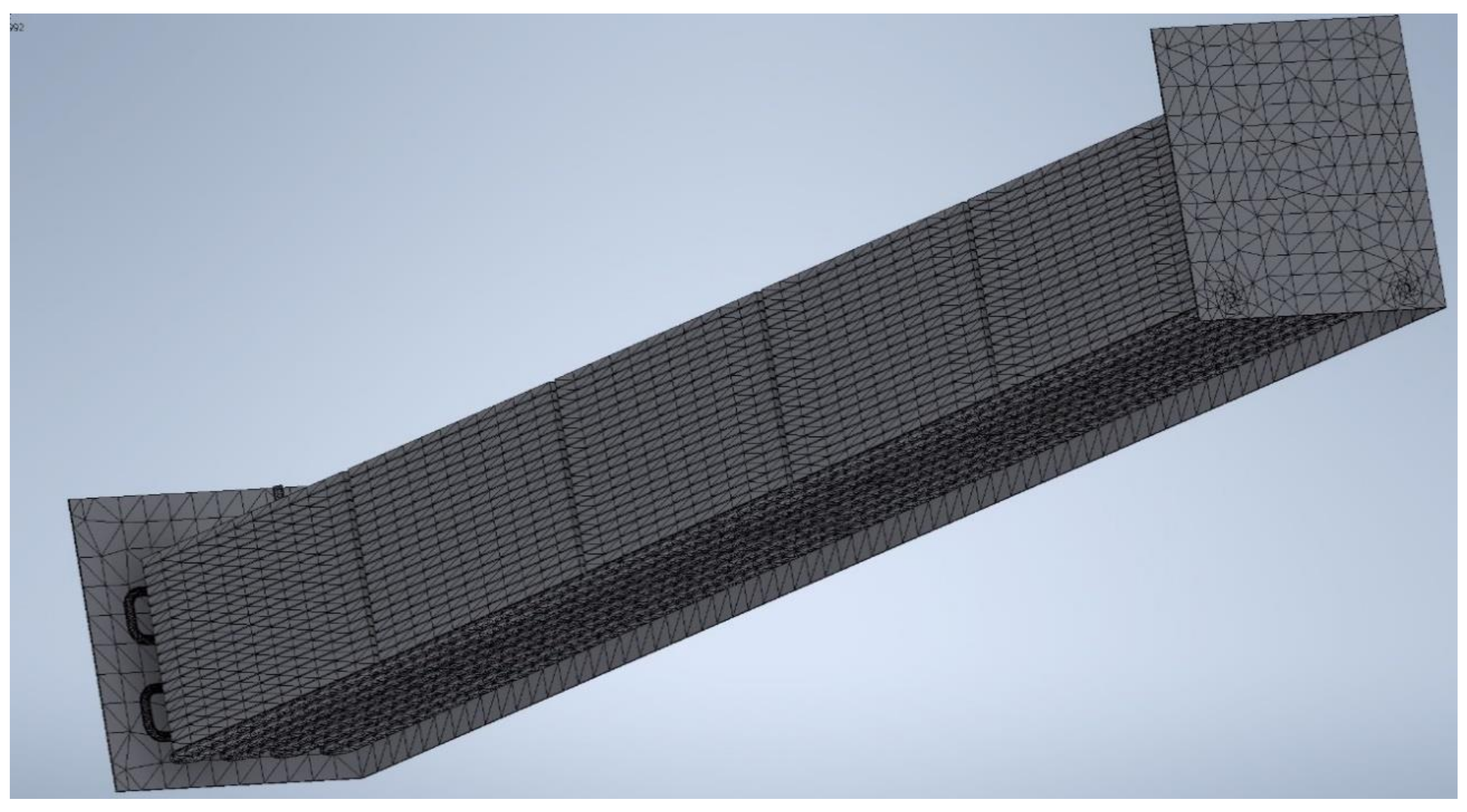
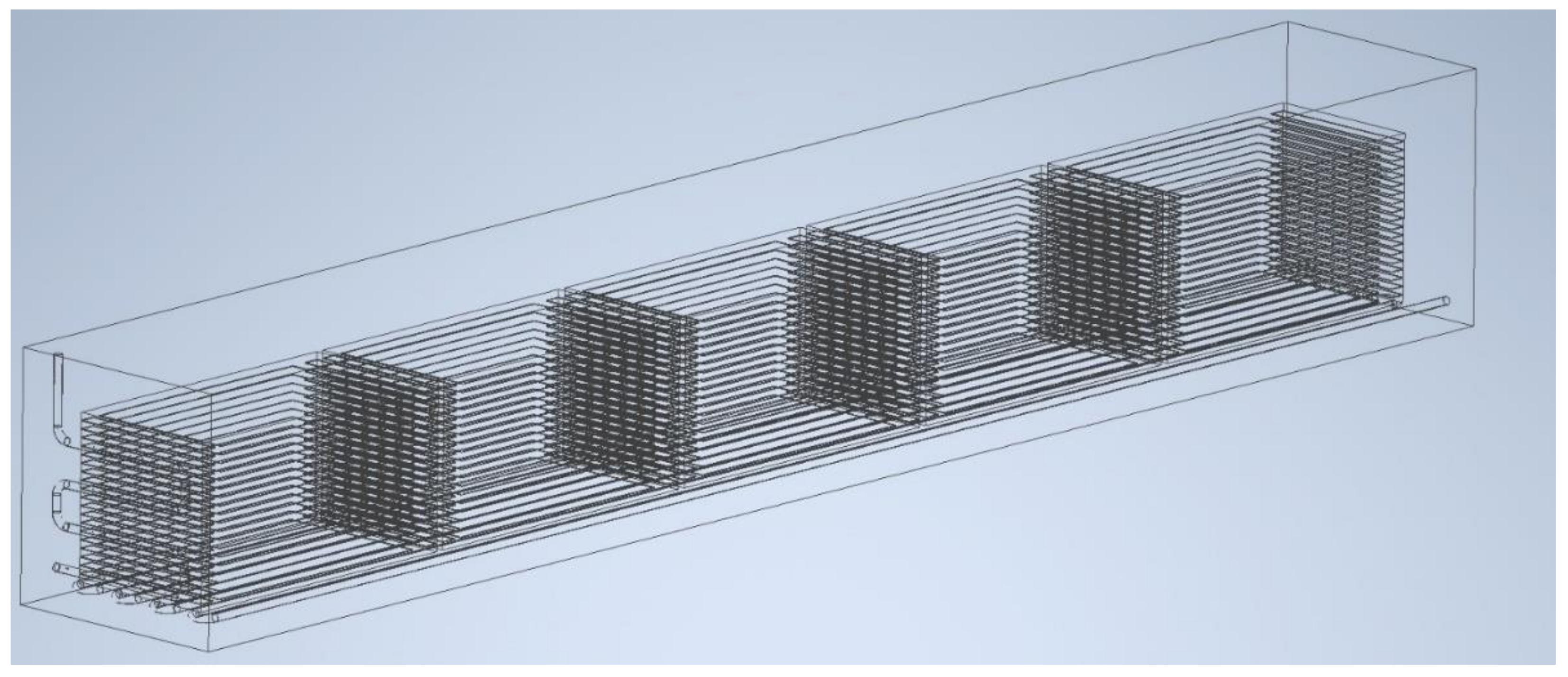
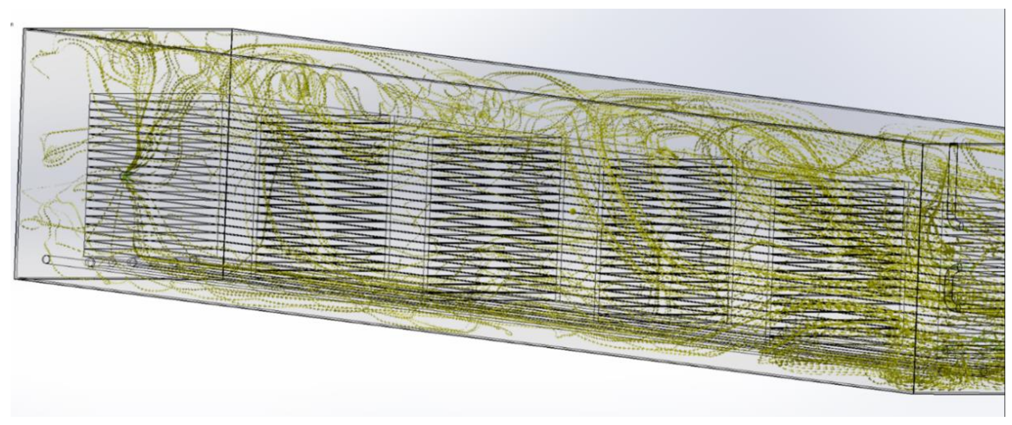
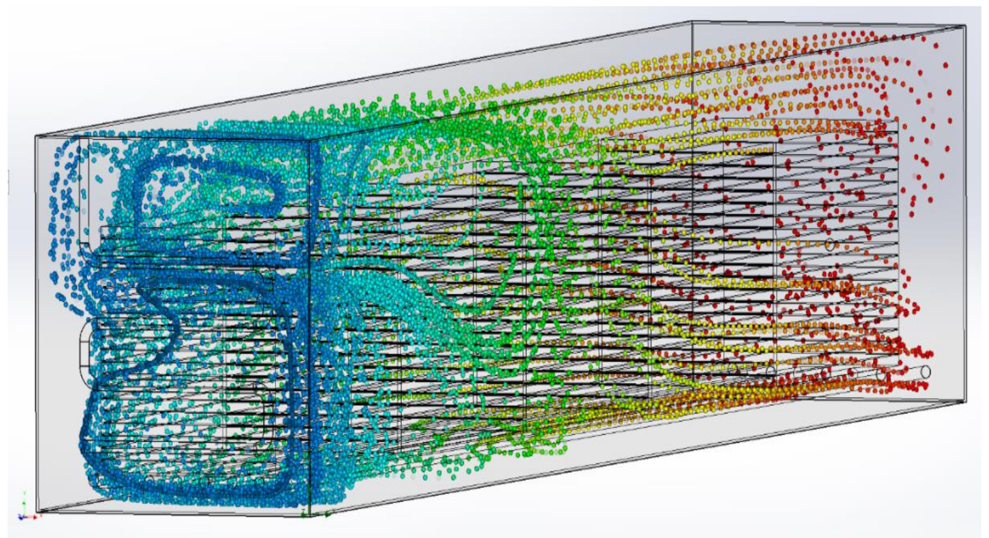
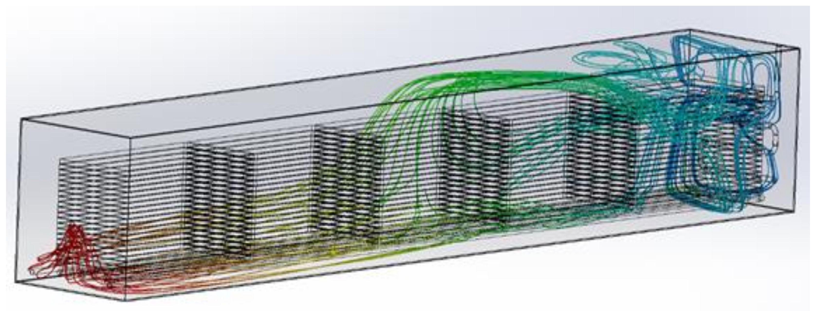
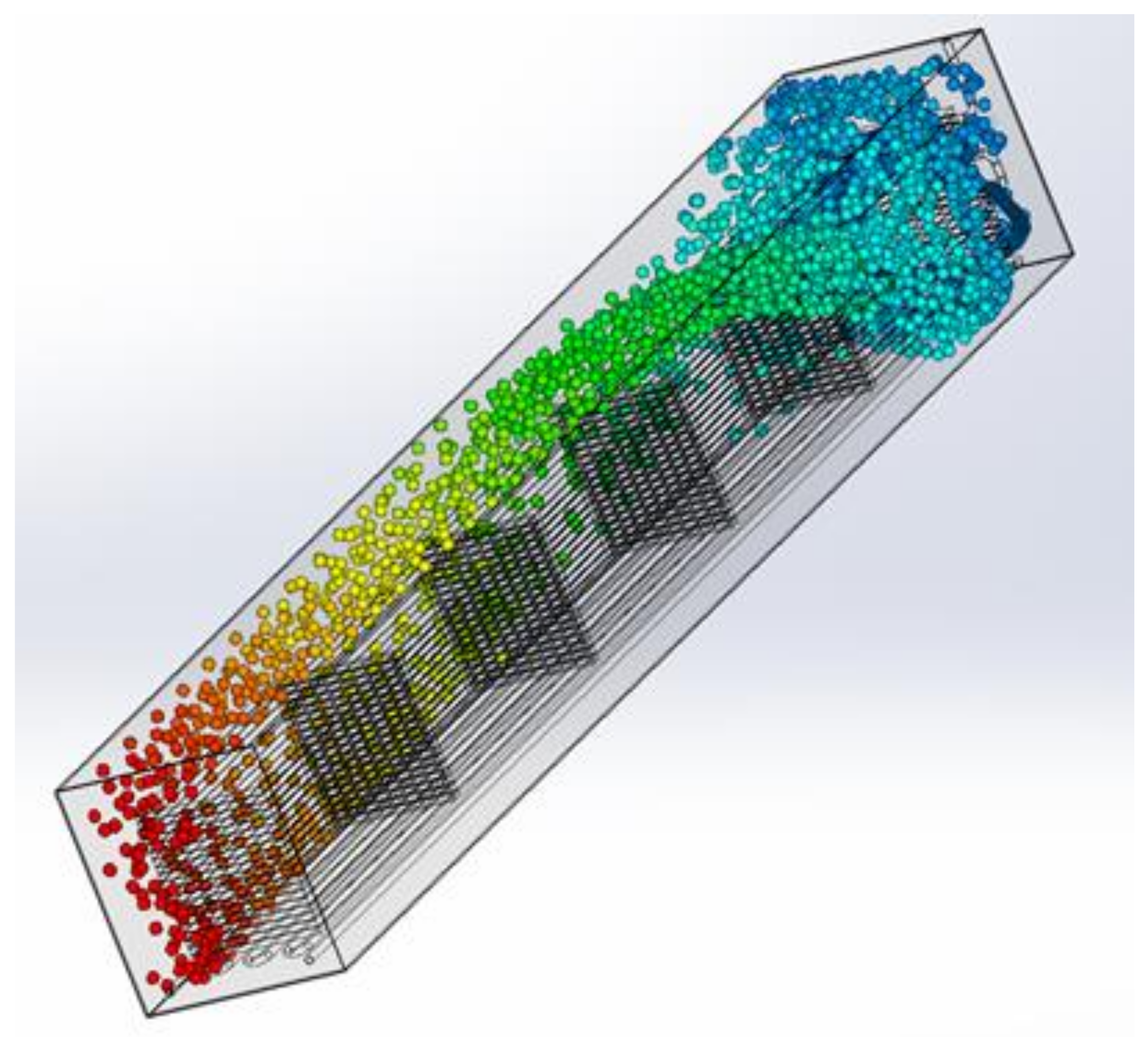
4.2. CFD Simulation of the Flow inside the Bathtub

Flow analysis was performed using the ANSYS CFX Workbench software and the Flow Simulation module in Solidworks. Due to the large size of the device, the lack of the axis of symmetry and the complicated geometry, it was decided that significant simplifications would be introduced for the purposes of simulation. The first one took place during the construction of the three-dimensional model of the installation used in the simulation. Some geometry was simplified, for example, by removing welded joints, and a low mesh resolution was also chosen. Such assumptions result from the small influence of such elements on the global behavior of the flowing liquid and the fact that with such large model sizes [28], increasing the mesh resolution does not significantly affect the accuracy of calculations or significantly affect the calculation time. The remaining simplifications resulted mainly from the adopted calculation model and the use of the necessary simplifications within them.
The following assumptions were made in the analysis:
  • the geometry is possibly consistent with the real one,
  • the liquid inlet velocity into the diffuser at the centerline of the tube is two meters per second. This is the standard velocity of the compressed fluid in the pipe elements assumed during the design,
  • the temperature of the liquid inside the bath is 35 °C. It is the operating temperature of the device assumed earlier. Due to the aforementioned high complexity of the model, it was decided that the flow during cold liquid heating would not be simulated,
  • phenomena related to gravitational interaction and cavitation were taken into account during the simulation,
  • During the simulation, it was assumed that all elements of the device were not moving. The effects related to device vibration were also not considered.
The simulation results in liquid flow paths inside the wood load and the bathtub itself, as presented on Figure 9. Due to the limited readability of the graphs (with about 150 flow paths, the image becomes unreadable), it is not possible to present the overall liquid flow in one graph at the same time. The flow paths shown in the pictures are strongly dependent on the adopted starting geometry for the calculations. One of the most important observations is the high complexity of movement inside the apparatus. You can observe both the movement of the liquid along the tub (from the inlet to the outlet), the movement of the liquid between the truss elements, as well as the vortices that can be observed on Figure 10 close to the jets. The presence of the latter indicates the turbulent nature of the flow, which, according to the mass transfer theory, translates into significantly higher values for the mass transfer coefficients compared to laminar and stationary fluid flows. It is also worth paying attention to the high mixing of the liquid; in the further parts of the bathtub, it can be observed (Figure 11) that the liquid flowing in the upper part passes through the load and then flows through the bottom part of the bathtub to the outlet. The flow of the liquid through almost the entire volume of the bath also ensures a more even concentration of the impregnating liquid and the temperature.
Another observation is that the fluid behavior near the diffuser is consistent with the assumptions. Due to the short distance from the load, the liquid is forced into the gaps between the girders and the phenomenon of avoiding the load by a significant part of the load is avoided, what can be seen on Figure 12. The distribution of the liquid is also as uniform as possible in a plane parallel to the diffuser. In further sections, the flow of liquid between the spaces between the load and the environment can be observed. It is not an intense movement, but it is present. This is due to the lower flow resistance outside the load. In this situation, increasing the distance between the trusses may help, but it will allow you to load a smaller amount of timber.
To sum up, the simulation confirms a significant intensification of the fluid movement inside the apparatus. The liquid flow paths indicate the turbulent nature of the flow, so it is possible to assume a significant intensification of the heat mass and mass transfer inside the bathtub. Thanks to this, it can be assumed that the adopted design assumptions and process parameters are correct.

5. Conclusions

  • The calculations and simulations performed show that it meets the requirements of mechanical and chemical resistance, and allows for continuous and safe operation.
  • The logical and mathematical analysis carried out allows us to adopt positive conclusions regarding the potential benefits of modifying the current method of carrying out the process, as well as operating parameters.
  • These benefits include shorter operating times, a higher and more reproducible product quality, and the management of process waste, such as wood waste, that powers the reheating furnace.
  • On the basis of the tests carried out, it was found that the repeatability of the process was modified in the case of the apparatus, which is strictly determined by weather conditions and temperature.
  • The introduced changes resulted in obtaining the repeatability of product parameters both between product parts and within one process (within one process). The efficiency of the process is also significantly increased, which allows both to achieve an increased product quality.
  • Made as part of the computer program, the optimization of parameters was also issued on the basis of the assumed equal impregnation and minimization of the risk of obtaining products of unsatisfactory quality.
Currently, in most plants, the wood impregnation process takes place at an ambient temperature. The wood is immersed in the impregnation and remains in it until the desired final parameters are achieved. Due to the fact that some of the bathtubs are located outside the building, it was not possible to use them when the ambient temperature is below zero. For this reason, it was decided that a heating element would be installed in the bathtub. Due to the limited amount of space, it was decided that a flat tube heat exchanger in the form of a coil would be installed. This solution guarantees the elimination of the so-called “dead zones” of the coil, i.e., places where minimal or no liquid flow is observed. In addition, in standard tubs, the conventional system in which impregnated elements are immersed in a stationary liquid is very ineffective, which is why the use of a flow mixer is a novelty. The liquid is sucked in at one end of the tub, compressed by a high-pressure pump, and then forced through a bank of nozzles at the other end of the tank. The nozzles are spaced in such a way that the liquid is pumped evenly inside the bathtub. An additional advantage of this solution is the lack of moving parts inside the bathtub. This minimizes the number of components that can fail, especially in such an aggressive environment.

Author Contributions

Conceptualization, Ł.A. and S.S.; Methodology, S.S., F.M., P.P. and M.G.; Software, F.M.; Validation, Ł.A. and S.S.; Formal analysis, S.S., F.M., P.P. and M.G.; Investigation, Ł.A.; Resources, F.M.; Data curation, Ł.A. and P.P.; Writing—original draft, S.S.; Writing—review & editing, S.S. and M.G.; Visualization, Ł.A.; Supervision, M.G.; Project administration, F.M. and P.P.; Funding acquisition, M.G. All authors have read and agreed to the published version of the manuscript.

Funding

This research received no external funding.

Institutional Review Board Statement

This study does not require ethical approval.

Informed Consent Statement

Not applicable.

Data Availability Statement

Not applicable.

Conflicts of Interest

The authors declare no conflict of interest.

References

  1. Krzysik, F. Nauka o drewnie; Pañstwowe Wydawnictwo Naukowe: Warszawa, Poland, 1978. [Google Scholar]
  2. PN-EN 335:1996; Trwałość Drewna i Materiałów Pochodnych. Definicja Klas Zagrożenia Ataku Biologicznego. Polski Komitet Normalizacyjny: Warsaw, Poland, 1996.
  3. Piasecki, M.; Wiejak, A. Metoda badania skuteczności ochrony drewna budowlanego przed działaniem mikroorganizmów glebowych. Pr. Inst. Tech. Bud. 2005, 34, 45–54. (In Polish) [Google Scholar]
  4. Ważny, J.; Karyś, J. Ochrona Budynków Przed Korozją Biologiczną; Warszawa 2001. ISBN 8321342051. Available online: https://sklep.drewno.pl/produkty/ksiazki/ochrona-drewna/ochrona-budynkow-korozja-biologiczna/ (accessed on 1 February 2023). (In Polish).
  5. Lutomski, K. Metody badań chemicznych środków ochrony drewna i technologii ich stosowania: Wydaw. Akademii Rolniczej im. Augusta Cieszkowskiego, Poznań. 2002. Available online: https://fbc.pionier.net.pl/details/nnlX43w (accessed on 1 February 2023). (In Polish).
  6. Lutomski, K. Metody badań chemicznych środkow ochrony drewna i technologii ich stosowania. Poznań. 1981. Available online: https://w.bibliotece.pl/57217/Metody+bada%C5%84+chemicznych+%C5%9Brodk%C3%B3w+ochrony+drewna+i+technologii+ich+stosowania (accessed on 1 February 2023). (In Polish).
  7. Lutomski, K. Impregnacja drewna metodami kapieli w chemicznych srodkach ochronnych. Przemysł Drzewny 2000, 51, 22–24. Available online: http://yadda.icm.edu.pl/yadda/element/bwmeta1.element.agro-article-f4484173-d184-4d22-8c46-d11c6ee1fb3a (accessed on 1 February 2023). (In Polish).
  8. Małozięć, D. Metody impregnacji ochronnej drewna. Ogólnopolskie Seminarium CNBOP Józefów. 2008. Available online: https://www.cnbop.pl/en (accessed on 1 February 2023).
  9. PL 191467 Agent for the Protective Treatment of Wood and a Method for the Protective Treatment of Wood. Application No. 345611, 2 January 2002.
  10. Kundzewicz, A. Rzeczywistość impregnacji drewna budowlanego w Polsce. Przemysł Drzewny 2011, 62. Available online: http://yadda.icm.edu.pl/yadda/element/bwmeta1.element.dl-catalog-fdc6f4d4-551f-455a-8a96-91b7b3db7af0 (accessed on 1 February 2023).
  11. FOBOS Home Page, FOBOS M-4 Datasheet. Available online: https://www.impregnatyfobos.pl/fobos-m4 (accessed on 1 February 2023).
  12. PN-EN 10296-1; Wymiary i Tolerancje dla Wybranych Typów rur Zgodnych z Normą. Polski Komitet Normalizacyjny: Warszawa, Poland, 2006.
  13. PN-EN 12667:2002; Właściwości Cieplne Materiałów i Wyrobów Budowlanych. Określanie Oporu Cieplnego Metodami Osłoniętej Płyty Grzejnej i Czujnika Strumienia Cieplnego. Wyroby o Dużym i Średnim Oporze Cieplnym. Polski Komitet Normalizacyjny: Warszawa, Poland, 2002.
  14. Katopodes, N. Free-Surface Flow. Environmental Fluid Mechanics; Butterworth-Heinemann: Oxford, UK, 2019; ISBN 978-0-12-815489-2. [Google Scholar]
  15. Miller, C. The Stokes-Einstein Law for Diffusion in Solution. Proc. R. Soc. Lond. A 1924, 106, 724–749. [Google Scholar] [CrossRef]
  16. Carbonell, R.; Whitaker, S. Heat and Mass Transfer in Porous Media. Fundamentals of Transport Phenomena in Porous Media. NATO ASI Ser. 1984, 82, 121–198. [Google Scholar] [CrossRef]
  17. My Floor Home Page, Encyklopedia drewna: Wilgotność. Available online: https://myfloor.pl/poradniki/encyklopedia-drewna-wilgotnosc/ (accessed on 1 February 2023).
  18. Powiatowe Centrum Edukacji Zawodowej Home Page, Wykonywanie plastycznej obróbki drewna. Available online: http://www.pcez-bytow.pl/download/plk/iii-2-tydzien-wykonywanie-plastycznej-obrobki-drewna.pdf (accessed on 1 February 2023).
  19. Drewno z przymrużeniem oka, Zupa z drewna–czyli……? Available online: https://drewnozprzymruzeniemoka.blog/2018/06/06/zupa-z-drewna-czyli/ (accessed on 1 February 2023).
  20. Święch, D. Wpływ temperatury na szybkość reakcji chemicznej, E-podręczniki AGH. 2019. Available online: https://epodreczniki.open.agh.edu.pl/tiki-index.php?page=Wp%C5%82yw+temperatury+na+szybko%C5%9B%C4%87+reakcji+chemicznej (accessed on 1 February 2023).
  21. Piersa, P.; Szufa, S.; Czerwińska, J.; Ünyay, H.; Adrian, Ł.; Wielgosinski, G.; Obraniak, A.; Lewandowska, W.; Marczak-Grzesik, M.; Dzikuć, M.; et al. Pine Wood and Sewage Sludge Torrefaction Process for Production Renewable Solid Biofuels and Biochar as Carbon Carrier for Fertilizers. Energies 2021, 14, 8176. [Google Scholar] [CrossRef]
  22. Adrian, Ł.; Szufa, S.; Piersa, P.; Mikołajczyk, F. Numerical Model of Heat Pipes as an Optimization Method of Heat Exchangers. Energies 2021, 14, 7647. [Google Scholar] [CrossRef]
  23. Siuda, R.; Kwiatek, J.; Szufa, S.; Obraniak, A.; Piersa, P.; Adrian, Ł.; Modrzewski, R.; Ławińska, K.; Siczek, K.; Olejnik, T.P. Industrial verification and research development of lime-gypsum fertilizer granulation method. Minerals 2021, 11, 119. [Google Scholar] [CrossRef]
  24. Adrian, Ł.; Szufa, S.; Piersa, P.; Kuryło, P.; Kurowski, K.; Pochwała, S.; Mikołajczyk, F.; Obraniak, A.; Stelmach, J.; Wielgosiński, G.; et al. Analysis and evaluation of heat pipe efficiency to reduce low emission with the use of working agents r134a, r404a and r407c, r410a. Energies 2021, 14, 1926. [Google Scholar] [CrossRef]
  25. PN-N-02101:1955; Normalna temperature odniesienia. Polski Komitet Normalizacyjny: Warszawa, Poland, 1955. (In Polish)
  26. Siczek, K.; Siczek, K.; Piersa, P.; Adrian, Ł.; Szufa, S.; Obraniak, A.; Kubiak, P.; Zakrzewski, W. The comparative study on the Li-S and Li-ion batteries cooperating with the photovoltaic array. Energies 2020, 13, 5109. [Google Scholar] [CrossRef]
  27. Kryszak, D.; Bartoszewicz, A.; Szufa, S.; Piersa, P.; Obraniak, A.; Olejnik, T.P. Modeling of Transport of Loose Products with the Use of the Non-Grid Method of Discrete Elements (DEM). Processes 2020, 8, 1489. [Google Scholar] [CrossRef]
  28. Stelmach, J.; Kuncewicz, C.; Szufa, S.; Jirout, T.; Rieger, F. The Influence of Hydrodynamic Changes in a System with a Pitched Blade Turbine on Mixing Power. Processes 2021, 9, 68. [Google Scholar] [CrossRef]
Figure 1. The 3D model of impregnation tub for wooden roof trusses.
Sustainability 15 04261 g001
Figure 2. The 3D model of laden tubes and impregnation tub for wooden roof trusses.
Sustainability 15 04261 g002
Figure 3. The actual appearance of the heating coil.
Sustainability 15 04261 g003
Figure 4. Position of the coil in the 3D model of impregnation tub for wooden roof trusses.
Sustainability 15 04261 g004
Figure 5. Elements of equipment modernization prepared for installation.
Sustainability 15 04261 g005
Figure 6. Compare the values of mass factors for different fluid velocities.
Sustainability 15 04261 g006
Figure 7. Mesh generated for mass transfer simulation. Even at a relatively low resolution, the number of simulation elements exceeds 500,000, and the number of nodes—1,000,000.
Sustainability 15 04261 g007
Figure 8. Model of liquids inside the bath used to simulate the behavior of liquids inside the apparatus.
Sustainability 15 04261 g008
Figure 9. Flow lines inside the tub.
Sustainability 15 04261 g009
Figure 10. Flow lines for a portion of the fluid flowing around the load- the colors represent the distance of the simulated liquid particle from the tub inlet, dark blue is the greatest distance, red is the shortest distance.
Sustainability 15 04261 g010
Figure 11. Flow lines for a fluid flowing through a cargo—the colors represent the distance of the simulated liquid particle from the tub inlet, dark blue is the greatest distance, red is the shortest distance.
Sustainability 15 04261 g011
Figure 12. Flow lines for a miscible liquid at the diffuser—the colors represent the distance of the simulated liquid particle from the tub inlet, dark blue is the greatest distance, red is the shortest distance.
Sustainability 15 04261 g012
Table 1. Experimental values of the surface mass emission factor of selected wood samples.
SampleMoisture Content [%]Value of the Surface Mass Emission Factor (T = 20 °C) [10−6 m/s2]Value of the Surface Mass Emission Factor (T = 40 °C) [10−6 m/s2]Increase [%]
Pine wood152.385.14116
Pine wood301.582.3649
Pine wood600.691.2277
Oak152.426.02149
Oak301.222.0971
Oak600.631.1786
Maple153.745.8757
Maple301.352.2567
Maple600.591.38134
Table 2. Indicative maximum heating times for a system without mixing.
Starting Temperature [°C]Real ConditionsCalculated Time to Reach Process Temperature [h]
−10A frosty day, tanks placed outside the buildings1.60
14The minimum temperature in the work rooms permitted by the law1.01
20Normal reference temperature acc.
PN-N-02101:1955 [25]
0.88
30Hot day0.66
Disclaimer/Publisher’s Note: The statements, opinions and data contained in all publications are solely those of the individual author(s) and contributor(s) and not of MDPI and/or the editor(s). MDPI and/or the editor(s) disclaim responsibility for any injury to people or property resulting from any ideas, methods, instructions or products referred to in the content.

