Abstract
The ancient levees used for flood control generally exist in the rainy areas of southern China. After years of operation, the levees have lots of problems, such as leakage, swelling, and cracking, which need to be reinforced. In this paper, combined with the characteristics of river water level fluctuations, the effect of the upside-down hanging well and curtain grouting reinforcement of the ancient levee is analyzed by a numerical method, and the variation law of the levee’s stability in the flooding process before and after reinforcement is explored. The study results show that the flooding process significantly affects the pore water pressure of the filling soil between the ancient levee and the well, and has a weak impact on that behind the well, which is conducive to the levee’s stability. The horizontal displacements of the levee and the fill present the opposite change law before and after reinforcement. Before reinforcement, the maximum horizontal displacement reached 2.75 cm, and the displacement was toward the Lan River. This was caused by the deformation of the soil squeezing the levee after the water level rose, which was extremely unfavorable to the levee’s stability. After reinforcement, the levee and fill shifted away from the river, mainly due to the hydrostatic pressures caused by the rising water level. The change in the stability safety factors of the reinforced levee is basically consistent with the flood fluctuation. The minimum value of the safety factors is 1.727, the maximum value is 2.273, and the safety factor only decreases by 24.02%, which is half of the change range of the safety factors before reinforcement. The stability of the reinforced ancient levee is largely improved.
1. Introduction
The phenomena that water level changes trigger bank slope instability and cause disasters often occur during the flood season every year [1,2,3], and this process involves complex transient flow problems of saturated–unsaturated soil [4,5,6,7]. The sudden drawdown of the water level has a significant impact on the bank slope stability [8,9,10]. Its stability is mainly affected by the initial water level, water level drawdown rate, drawdown amplitude, seepage coefficients, and changes in the groundwater level [11,12,13,14]. The seepage process alters the soil pore water pressure and then changes its physical and mechanical properties [15,16,17]. The periodic change in the water level will also bring about irreversible damage to soil properties, which will initiate potential safety hazards [18]. For unsaturated soil, the increasing water content will reduce its mechanical properties, and even lead to cracks [19,20].
Southeast China is rich in water and rainfall, with crisscross river networks, and there are many problems caused by seepage in engineering [21,22]. In ancient times, the levees built by the waterfront in many towns were not only military facilities but also flood control facilities [23]. They still play a huge role in flood control, and also add a strong cultural heritage to cities and towns, becoming city cards, which is of great significance to local cultural, economic, and social development [24,25,26,27,28]. However, in recent years, the news of the destruction of ancient levees built along rivers has been reported frequently, which has aroused concern from all walks of life about the protection of ancient buildings. The engineering geological and hydrogeological conditions of the ancient levees are complex, and there are many factors affecting their destruction. Through historical changes, the factors affecting each destruction are different, which adds difficulties to the analysis of their destruction mechanism. It is not only blind to carry out engineering reinforcements when the failure mechanism is unknown but also reinforcement measures may not play their role. Indoor and outdoor tests, on-site monitoring, and investigation are very important and necessary for accident analyses and engineering reinforcements. However, the above methods are difficult to meet extreme working conditions of the levees and analyze various working conditions in the process of engineering practices, which not only cannot fully reflect the impact of influencing factors on the stability of the ancient levees, but also have the problems of a long time and large capital investment. For the ancient flood control levee that affects the safety of flood discharge and is in urgent need of reinforcement, it is necessary to evaluate the influence of the main factors on its stability before and after reinforcement under a certain working condition. It is the best choice to use numerical simulation technology to study it in combination with some indoor and outdoor tests, monitoring, and survey technologies. Taking Lanxi’s ancient levee in southeast China as an example, this paper discusses the effect of anti-seepage reinforcement by adopting the upside-down hanging well and curtain grouting technology with a numerical method.
The technology scheme of the upside-down hanging well and curtain grouting is rarely used in the construction of the ancient levee reinforcement, and the impact on the levee’s stability during the water level change process is not clear. Therefore, this paper intends to select a typical section for an in-depth study and analyze the stability change laws of the ancient levee before and after reinforcement during floods of the Lan River. According to the characteristics of Lan River water level changes, combined with indoor tests and on-site observation, the stability change of Lanxi’s ancient levee before and after reinforcement is analyzed through the construction of a numerical model by selecting the maximum flooding process in recent years, the influence of water level change on the stability of the ancient levee after anti-seepage reinforcement is evaluated, and the evolution in the law of the stability safety coefficients during the flooding process and the reinforcement effect are quantitatively revealed. The study provides a theoretical basis for risk identification, prevention, and control, and the selection of reinforcement measures for ancient flood control levees.
2. Engineering Background
The ancient levee is located in the upper reaches of Lan River in Lanxi City, Zhejiang Province, China, and the lower reaches of the intersection of Qu River and Jinhua River (Figure 1a). It was built during the Northern Song Dynasty (at present, there are still about 600 m left, with a history of more than 1000 years) and rebuilt in the seventh year of Zhengde of the Ming Dynasty (1512). The levee is also used as a city wall and has military defense and flood control functions. As the water level at the intersection of the three rivers changes dramatically, it has been destroyed by water many times in history. Up to now, the levee is still used as an important flood control facility (Figure 1b), which plays a significant role in local flood control. The surface near the water side of the ancient levee is built with strip stones, the masonry material is local red sandstone, and the bonding material is a traditional lime slurry. Behind the stone levee is miscellaneous fill with a loose structure, poor uniformity, and large seepage coefficient, and the levee body has collapsed many times (Figure 1c,d). There are a lot of seepage and stability problems in the levee body and foundation (Figure 1e), and many sections also appear bulging and cracking (Figure 1f).
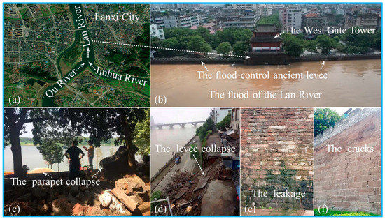
Figure 1.
The location and damage characteristics of Lanxi’s ancient levee. (a) The location of the ancient levee, (b) the ancient levee under floods, (c) the failure of the upper part of the ancient levee, (d) the collapse of the ancient levee, (e) the seepage of the ancient levee, and (f) the bulging and cracking of the ancient levee.
In history, Lanxi’s ancient levee has been damaged and repaired many times. The last serious collapse occurred in the section near the West Gate Tower, and the repair of this section was completed in 2015. During the “6.25” flood on 25 June 2017, several sections of the ancient levee along the river burst, and some of them collapsed. The situation was critical. Floods poured into the old city of Lanxi, causing flooding in the urban area, and lots of residents’ lives were seriously affected. At that time, the flood control standard of the ancient levee at the West Gate Tower section could not withstand the flood with a 20-year return period; thus, there were potential safety hazards during the flood season.
From March 2020 to August 2021, the local management department strengthened the ancient levee of the West Gate Tower section by combining the upside-down hanging well and curtain grouting (Figure 2a). The purpose of the reinforcement is to cut off the seepage passage of the levee’s body and foundation. The upside-down hanging well is one of the excavation methods for the shaft and foundation pit. It is similar to the shaft made from top to bottom. Generally, the upper layer is completed first, then the lower layer is excavated after the support is completed, and then the pouring is carried out from bottom to top. Considering the complex living environment near the ancient levee and the loose filling behind it, the upside-down hanging well excavation method is adopted, which can be used for excavation and support. For upside-down hanging and well construction, the upper open trench (Figure 2b) shall be excavated first, and the concrete longitudinal beam of the straight trench opening shall be poured. The upside-down hanging well shall be built below. It is backfilled with C25 concrete, and the diameter and depth are 1.6 m and 5.0 m (Figure 2c–f). Two rows of cement grouting are used for the anti-seepage reinforcement of the lower foundation of the well, with a row spacing of 0.5 m. The hole spacing at the side close to the levee is 2.0 m and the second row is 1.0 m. The lower 1.0 m depth is bedrock grouting (Figure 2g).
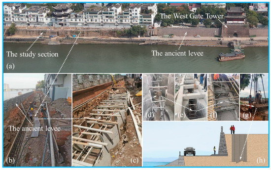
Figure 2.
The construction process of the upside-down hanging well and curtain grouting. (a) The construction scene of the levee reinforcement, (b) the foundation excavation, (c) the cast in situ concrete formwork support for the upside-down hanging well, (d) the upside-down hanging well wall after pouring, (e) the fabrication of the reinforcement cage in the well, (f) the concrete backfilling, (g) the curtain grouting, and (h) the schematic diagram of the anti-seepage reinforcement system.
3. Materials and Methods
3.1. Numerical Model Calculation Theory
The seepage coefficient of unsaturated soil is a quantity that changes constantly with the variation of the soil moisture state or matrix suction [29,30]. The generalized two-dimensional seepage differential equation based on Darcy’s law is used to describe the transient flow of water under unsaturated conditions at any position in the soil profile, and its general expression is as follows [31,32,33]:
where H is the total water head, m; , are the seepage coefficients in x and y directions, respectively, cm/s; is the unit volume flow, 1/s; t is the time, s; and is the water content per unit volume of soil, %.
The instability and failure of ancient levees are mainly caused by the deformation and extrusion of the fill. During the water level change in the Lan River, the groundwater level of the fill is constantly changing. The soil below the free water surface is saturated, and the fill above the free water surface is considered unsaturated soil. The modified Mohr–Coulomb criterion is used to describe the shear strength of saturated–unsaturated soil as follows [34,35]:
where is shear strength, kPa; is effective cohesion, kPa; is the effective internal friction angle, °; is the normal stress at the center of the bottom surface of each block, kPa; is pore gas pressure, kPa; and is the internal friction angle corresponding to the matrix suction, °. The following formula is used for calculation [36,37]:
where is the saturated volume water content of the soil, %; and is the residual volume water content of the soil, %.
The levee’s stability is usually evaluated by safety factors [38,39], and they are calculated by the finite element method [40]:
where is the safety factor; is the anti-sliding shear force, kN, , of which is the length of the bottom surface of the calculated slider, m; and is the sliding shear force, kN, , of which is the sliding shear stress, kPa.
3.2. Calculation Parameters and Boundary Conditions
3.2.1. Physical and Mechanical Parameters
Geometric Parameters
According to the geological and hydrological conditions and the representativeness of the layout of the ancient levee in the whole reinforcement section, the geological cross-section of the typical cross-section of Lanxi’s ancient levee is shown in Figure 3. The geological materials of this section are divided into four layers, of which the first to second layers (I1, I2) are both artificial fills, and the third and fourth layers are, respectively, sandy gravel cobble and argillaceous silt rock layers. The levee is built with red sandstone, about 8.0 m high, of which the parapet is 1.0 m high, and the included angle between the levee and the horizontal plane is 88°.
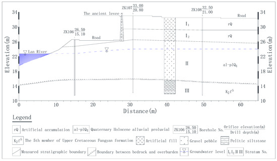
Figure 3.
The geological cross-section of the typical section.
According to the geological cross-section of the above typical section, the numerical model before and after the ancient levee reinforcement is established, and the quadrilateral element rectangular grid is used for subdivision, with the grid side length set as 0.5 m. The geometric dimensions and grid division of the numerical model are shown in Figure 4 and Figure 5.
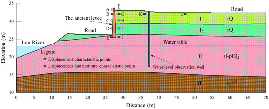
Figure 4.
The schematic diagram of the geometric dimension and grid division of the numerical model before reinforcement.
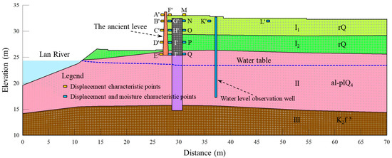
Figure 5.
The schematic diagram of the geometric dimension and grid division of the numerical model after reinforcement.
Performance Parameters of the Rock and Soil
The artificial fill soil samples are taken along the height of the typical section of the ancient levee for particle analysis. The particle grading curve is shown in Figure 6. The mass of soil samples with particle size larger than 0.075 mm shall not exceed 50% of the total mass, the liquid and plastic limits are 44% and 27%, the plastic index is 17, and the filling type is silty clay.
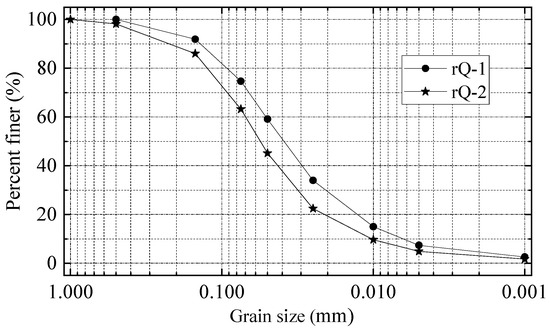
Figure 6.
The particle grading curves of the soil samples.
The physical and mechanical property parameters of the rock and soil of the numerical model are determined based on the field investigation data and laboratory tests, as shown in Table 1.

Table 1.
The physical and mechanical performance parameters of the rock and soil.
Hydraulic Parameters
The seepage coefficients of saturated rock and soil in the geological cross-section of the typical ancient levee section are shown in Table 2.
Table 2.
The seepage coefficients of the saturated rock and soil in each layer.
The soil water characteristic curve (SWCC) of the fill is obtained by fitting the parameters of the Van Genuchten empirical model after measuring the reshaped soil samples with the pressure plate method. The Van Genuchten model expression is as follows [41]:
where is matrix suction, , kPa; α is the parameter related to the intake value, 1/kPa; and n and m are the curve fitting parameters, of which .
The SWCC obtained by the above method is shown in Figure 7a. The seepage coefficients of saturated-unsaturated soils are also calculated based on the Van Genuchten empirical model [42]:
where and k are the seepage coefficients of saturated and unsaturated soils, respectively, cm/s; and Se is relative saturation, %, and it is calculated by the following formula [43]:
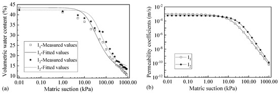
Figure 7.
The SWCCs and relationship curves between seepage coefficients and matrix suctions. (a) The SWCCs and (b) the relationship curves between seepage coefficients and matrix suctions.
The relationship curves between the seepage coefficients of unsaturated soil and the matrix suctions are calculated by Formula (6), as shown in Figure 7b. The sand gravel cobble layer (ΙΙ) and argillaceous siltstone (ΙΙΙ) are under the water surface, and their seepage coefficients are taken as saturated seepage coefficients. The seepage of the levee is generated from the red sandstone brick joint, which is a macro joint. The seepage coefficients have little change in the saturated–unsaturated state. The saturated seepage coefficients are taken in the calculation process.
3.2.2. Boundary Conditions
Hydraulic Boundary Conditions
The ancient levee is located downstream of the intersection of the Lan River, Qu River, and Jinhua River, and the water level fluctuates violently. The water level change process of the river reached near the ancient levee in five recent years is shown in Figure 8.
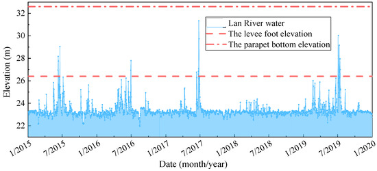
Figure 8.
The water level changes in the Lan River in five recent years.
To simulate the impact of water level changes on the stability of Lanxi’s ancient levee, according to Figure 8, the maximum flood in five recent years occurred in June 2017 and was selected as the boundary condition of transient water level and hydrostatic pressure, and a total water head varying with time was applied from the bank slope of Lan River to the levee’s body, as shown in Figure 9.
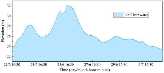
Figure 9.
The flooding process of the Lan River in 2017.
Stress/Strain Boundary Conditions
The horizontal displacement constraints are applied at the left and right ends of the numerical model, and horizontal and vertical constraints are applied at the bottom.
4. Results and Discussions
SEEP/W, SIGMA/W, and SLOPE/W are used to calculate the moisture field, stress field, and stability of the ancient levee. The calculation results and relevant discussions are as follows.
4.1. Seepage Analyses
Under the water level fluctuations of the Lan River, the water field of the filling behind the levee varies with time and location. The relationship curves of the pore water pressures of the characteristic points G′, H′, I′, and J′ of the reinforced ancient levee and the characteristic points G, H, I, and J without reinforcement with time are shown in Figure 10.
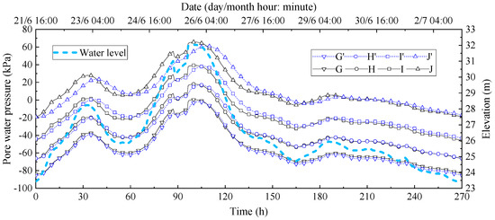
Figure 10.
The pore water pressure change of the ancient levee fill during the flood.
It can be seen in Figure 10 that the change law of the pore water pressures of the reinforced and unreinforced ancient levee fills are consistent with the water level fluctuation law of the Lan River. Because the soil seepage process takes a certain time, the change of pore water pressures is slightly delayed in time, and the change rate is smaller than the water level change rate. The characteristic points G′, H′, I′, and J′ are closer to the ancient levee than the characteristic points G, H, I, and J, while the lag time of the pore water pressure change of the characteristic points G′, H′, I′, and J′ of the levee filling is increased, which may be the blocking effect of the upside-down hanging well and curtain grouting on seepage. In space, the pore water pressures of G′, H′, I′, and J′ decrease with increasing depth.
To explore the change law of the pore water pressures after low permeability fill and upside-down hanging well, the characteristic points G′, H′, I′, and J′ and N, O, P, and Q are taken to analyze the change law of the pore water pressures, as shown in Figure 11.
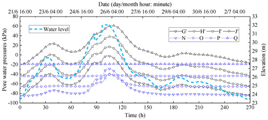
Figure 11.
The pore water pressure changes of the ancient levee fill during the flood.
It can be seen in Figure 11 that the pore water pressures at the characteristic points N, O, P, and Q of the soil do not change much during the flooding process after setting up the upside-down hanging well and curtain grouting, and at points P and Q, they almost do not change. The pore water pressures at points N and O have significant changes before and after the flood peak, but the values are negative, which shows that the backfill behind the well is always in an unsaturated state during the flooding process. The upside-down hanging well and curtain grouting reinforcement measures have played a good anti-seepage role.
To explore the variation law of pore water pressures of the levee filling, an analysis is performed at points 10 m, 20 m, and 30 m horizontally from the characteristic points I′ and I (expressed as I′-10 m, I′-20 m, I′-30 m and I-10 m, and I-20 m and I-30 m), as shown in Figure 12.
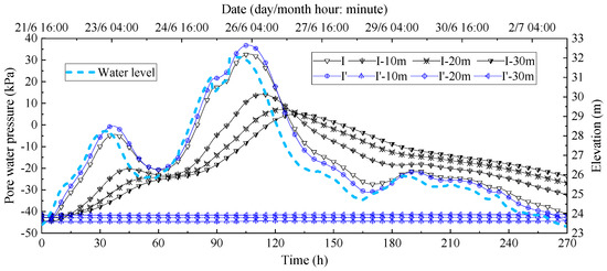
Figure 12.
The pore water pressure changes of the fill at the characteristic points during the flood.
It can be seen in Figure 12 that before reinforcement, with the increasing distance between the soil and the ancient levee, the variation range of the pore water pressures decreases continuously, and generally changes significantly with the varying flood level. The water level variation has an obvious influence on the pore water pressures of the fill near the levee (Point I). At the highest water level, the pore water pressure at this point reaches above 30 kPa. There is little difference between the pore water pressure at 20 m and 30 m from the horizontal point I, and at about 5 kPa, the change amplitude is relatively small, and the time delay is long. After reinforcement, the pore water pressure at point I′ changes significantly, while the difference between the pore water pressures of the three points 10 m, 20 m, and 30 m horizontally from point I′ is very small, and the values are always between −45 kPa and −40 kPa.
From the above analyses, it can be seen that the water level fluctuation of the Lan River significantly affects the pore water pressures at the lower part of the ancient levee before reinforcement. After the anti-seepage treatment of the upside-down hanging well and curtain grouting, the flooding process has a significant impact on the soil pore water pressures between the ancient levee and the upside-down hanging well, showing a similar change law to that before reinforcement. Behind the well, the water level change has little influence on the pore water pressures. The drastic change will certainly have an impact on the deformation and displacement of the fill, thus causing the fill to squeeze the levee, causing the deformation with the water level fluctuation. After reinforcement, the soil behind the upside-down hanging well is not affected much by the change in the river’s water level, which is beneficial to the levee’s stability.
4.2. Displacement Analyses
During the flooding process, the displacement change law of the ancient levee and fill along the horizontal direction before and after reinforcement is shown in Figure 13. In the following figures, the negative and positive values of the horizontal displacements represent the displacement toward and away from the Lan River.
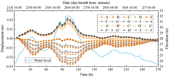
Figure 13.
The displacement changes of the ancient levee and fill in the horizontal direction during the flood.
It can be seen in Figure 13 that the horizontal displacement change of the ancient levee is basically consistent with the horizontal deformation law of the fill during the flooding process, and its horizontal displacements before and after reinforcement are opposite. Before reinforcement, the maximum horizontal displacement of point A reached 2.75 cm, and the displacement was toward the Lan River. This was caused by the soil deformation squeezing the levee after the water level rose. This deformation was extremely unfavorable to the levee’s stability. The change of the horizontal displacement at other characteristic points is also significant, and the variation amplitude between different positions is large. This phenomenon is mainly caused by the change in the pore water pressures. After reinforcement, the ancient levee and the fill shifted away from the direction of the Lan River, which was triggered by the hydrostatic pressure caused by the rising water level. It also showed that during the flooding process, the soil moisture behind the upside-down hanging well and curtain grouting changed little, and the stability of the fill was good. There is no obvious difference between the horizontal displacement of the ancient levee and the fill. The fill displacement is generally larger than the levee displacement. The maximum horizontal displacement of point A′ is 2.16 cm, 0.59 cm less than that before reinforcement. After reinforcement, the displacement direction of the ancient levee changes and the displacement value decreases, which is beneficial to its stability.
During the flooding process, the displacement change law of the upside-down hanging well and the backfill along the horizontal direction after reinforcement is shown in Figure 14.
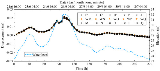
Figure 14.
The displacement change of the upside-down hanging well and backfill in the horizontal direction during the flood.
It can be seen in Figure 14 that the horizontal displacement change law of the well and fill is consistent with the flood level change law after reinforcement, and the displacement occurs in the direction away from the river, and the difference between them is small. This is consistent with the above analyses. After reinforcement, the hydrostatic pressures generated by the river water level play a major role. Due to the good anti-seepage treatment effect, the pore water pressures of the fill at the well back have almost no change; thus, the volume deformation of the soil is small, and the impact on the displacement of the upside-down hanging well is very limited.
Under the above circumstances, the horizontal displacements of the points far from the well are more insensitive to the change in the river water level. To explore the horizontal displacement of the ancient levee and the fill before and after reinforcement, the horizontal characteristic points B, G, K, and L before reinforcement and the horizontal characteristic points B′, G′, K′, and L′ after reinforcement are extracted, and the change law of their horizontal displacement is analyzed, as shown in Figure 15.
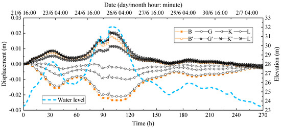
Figure 15.
The change of the characteristic points along the horizontal displacements before and after reinforcement during the flooding process.
It can be seen in Figure 15 that the changes of characteristic points at different locations in the horizontal direction are consistent with the above analysis before and after reinforcement. The change amplitude decreases and the displacement direction alters, which is beneficial to the stability of the ancient levee.
Before and after reinforcement, the vertical displacement change law of the ancient levee and fill during the 2017 flooding process is shown in Figure 16. In the figure, the negative and positive values represent downward and upward displacement, respectively.
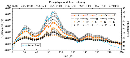
Figure 16.
The displacement change of the ancient levee and fill in the vertical direction before and after reinforcement during the flood.
It can be seen in Figure 16 that the vertical displacement of the fill near the ancient levee is relatively large before reinforcement. The maximum vertical displacement of points A, E, F, and J is 1.83 cm, 1.75 cm, 2.76 cm, and 2.06 cm. After reinforcement, the maximum vertical displacement of points A′, E′, F′, and J′ is 1.40 cm, 0.76 cm, 1.21 cm, and 0.85 cm, respectively. The vertical displacement of the ancient levee and fill after reinforcement is greatly reduced, and the seepage change has little impact on soil deformation.
4.3. Stability Analyses
The water level variation in the Lan River will cause changes in soil, water, and stress fields. Due to the anti-seepage effect of the upside-down hanging well and curtain grouting after reinforcement, it is difficult for the river water to penetrate the fill behind the well, which dramatically improves the safety factors of the ancient levee. The relationship curves between the safety factors of the ancient levee before and after reinforcement during the 2017 flooding process are shown in Figure 17.
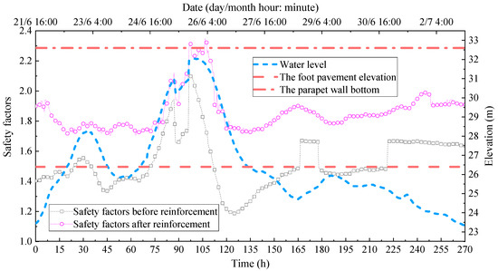
Figure 17.
The variation of the safety factors of the ancient levee before and after reinforcement during the flooding process.
It can be seen in Figure 17 that before reinforcement, the safety factors of the ancient levee were significantly affected by the water level change. The safety factors have been largely improved as a whole after reinforcement, and the change range in value has also decreased markedly. In the flood fluctuation process, the safety factors of the ancient levee before reinforcement changed dramatically, and their change rates were larger than the variation rates of the water level. In the water level falling process, the safety factor reaches the minimum value (1.185). After reinforcement, the change range of the safety factors obviously declines, the minimum value is 1.727, and occurs in the process of the water level decline. Before reinforcement, the water level corresponding to the minimum safety factor (27.65 m) was lowered from the flood peak (32.04 m). During this process, the water level changed by 4.38 m, and the safety factor decreased by 41.22%. After reinforcement, the maximum safety factor reached 2.273, and the safety factor only decreased by 24.02% during this flooding process. The above analysis shows that the stability and safety of the ancient levee strengthened by the upside-down hanging well and curtain grouting have been significantly improved.
4.4. Result Verification
To verify the correctness of the above calculation results, the water level monitoring data and the levee foot pavement displacement measured data during the construction period are selected for comparative analyses of the calculation sections of the ancient levee, as shown in Figure 18 and Figure 19.
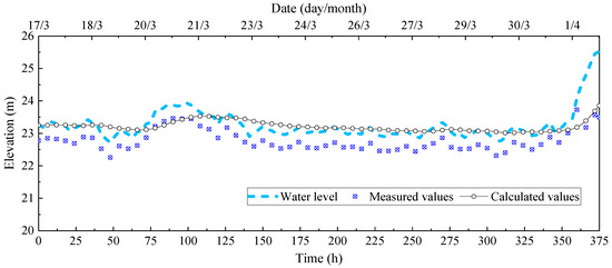
Figure 18.
The comparison between monitoring data and calculated values of the water level near the section from 17 March to 1 April 2021.
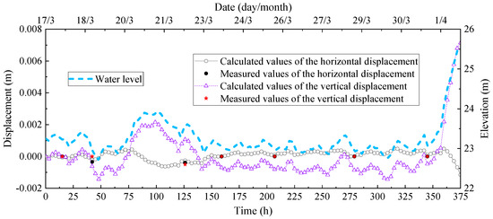
Figure 19.
The comparison between measured data and calculated values of the horizontal and vertical displacement of the levee’s foot pavement during the construction period.
It can be seen in Figure 18 that the calculated and monitored groundwater levels change with the Lan River water level, and their change laws are consistent, which is basically consistent with the calculation results. According to Figure 19, the measured data of the horizontal and vertical displacements of the levee’s foot pavement during the construction period are also in good agreement with the calculation results. Since the stability safety factors cannot be verified by tests or monitoring data, we can see the change laws of the stability safety factors with the water level before and after reinforcement. The calculation results are basically consistent with the actual situation of the project. The above analyses show that the selection of the seepage, displacement, and stability calculation methods and parameters is correct.
5. Conclusions
There is a lack of systematic analysis and research on the use of the upside-down hanging well and curtain grouting for the anti-seepage reinforcement of the ancient levee. This paper studies the stability change law of the ancient levee during the flooding process before and after reinforcement. The main conclusions are as follows:
After reinforcement, the flooding process significantly affects the pore water pressure of the filling soil between the levee and the upside-down hanging well, showing a similar change law as before reinforcement. The change in the water level has little influence on the fill pore water pressure, which is beneficial to the ancient levee’s stability.
The horizontal displacement of the ancient levee and the fill presents the opposite change law before and after reinforcement during the flooding process. Before reinforcement, the maximum horizontal displacement of the upper part of the levee reached 2.75 cm, and it was toward the Lan River. This was caused by soil deformation squeezing the levee after the water level rose. After reinforcement, the ancient levee and fill shifted away from the Lan River, mainly due to the hydrostatic pressure caused by the rising water level.
The safety factors of the reinforced ancient levee also fluctuated significantly with flood fluctuation, and the change was basically consistent with the water level variation. Their minimum and maximum values were 1.727 and 2.273, respectively. During water level fluctuation, the safety factor only decreased by 24.02%, which was half of the change range of the safety factors before reinforcement. The stability of the reinforced levee is largely improved.
Author Contributions
Writing—original draft preparation, Y.T. and Z.Q.; writing—review and editing, S.G. and H.Z.; funding acquisition, Z.Q. and J.Z.; formal analysis, Z.G., T.C. and Z.H.; investigation, Z.Q., S.G. and J.Z.; revision, editing, and English proofreading, Z.Q. All authors have read and agreed to the published version of the manuscript.
Funding
This research was supported by the scientific research foundation of Zhejiang University of Water Resources and Electric Power (xky2022013), the Major Science and Technology Plan Project of Zhejiang Provincial Department of Water Resources (RA1904), and the Zhejiang Provincial Nature Fund Project (ZJWZ23E090009).
Acknowledgments
The authors thank the engineering management department at the Zhejiang Design Institute of Water Conservancy, Hydro-Electric Power Co., Ltd., and the construction company for their support.
Conflicts of Interest
The authors declare no conflict of interest.
References
- Yang, B.; Yin, K.; Xiao, T.; Chen, L.; Du, J. Annual variation of landslide stability under the effect of water level fluctuation and rainfall in the Three Gorges Reservoir, China. Environ. Earth Sci. 2017, 76, 564. [Google Scholar] [CrossRef]
- Al-Labban, S.; Chopra, M. Effect of the core on the upstream stability of dams under sudden drawdown conditions. Ifcee 2018, 2018, 324–332. [Google Scholar] [CrossRef]
- Li, C.; Tang, H.; Wang, Y. Study on the deformation mechanism of reservoir landslides considering rheo-logical properties of the slip zone soil: A case study in the Three Gorges Reservoir region. Sustainability 2020, 12, 6427. [Google Scholar] [CrossRef]
- Zhang, Z.; Qian, M.; Wei, S.; Chen, J. Failure Mechanism of the Qianjiangping Slope in Three Gorges Reservoir Area, China. Geofluids 2018, 2018, 3503697. [Google Scholar] [CrossRef]
- Ku, C.; Liu, C.; Tsai, F.T.-C. A Novel Radial Basis Function Approach for Infiltration-Induced Landslides in Unsaturated Soils. Water 2022, 14, 1036. [Google Scholar] [CrossRef]
- Azadi, A.; Esmatkhah Irani, A.; Azarafza, M.; Hajialilue Bonab, M.; Sarand, F.B.; Derakhshani, R. Coupled numerical and analytical stability analysis charts for an earth-fill dam under rapid drawdown conditions. Appl. Sci. 2022, 12, 4550. [Google Scholar] [CrossRef]
- Berilgen, M.M. Investigation of stability of slopes under drawdown conditions. Comput. Geotech. 2007, 34, 81–91. [Google Scholar] [CrossRef]
- Dykes, A.P.; Bromhead, E.N. New, simplified and improved interpretation of the Vaiont landslide mechanics. Landslides 2018, 15, 2001–2015. [Google Scholar] [CrossRef]
- Maihemuti, B.; Wang, E.; Hudan, T.; Xu, Q. Numerical Simulation Analysis of Reservoir Bank Fractured Rock-Slope Deformation and Failure Processes. Int. J. Géoméch. 2016, 16, 04015058. [Google Scholar] [CrossRef]
- Li, S.; Sun, Q.; Zhang, Z.; Luo, X. Physical modelling and numerical analysis of slope instability subjected to reservoir impoundment of the Three Gorges. Environ. Earth Sci. 2018, 77, 138. [Google Scholar] [CrossRef]
- Sun, G.; Lin, S.; Jiang, W.; Yang, Y. A Simplified Solution for Calculating the Phreatic Line and Slope Stability during a Sudden Drawdown of the Reservoir Water Level. Geofluids 2018, 2018, 1859285. [Google Scholar] [CrossRef]
- Shi, L.; Sun, G. Improvement of the finite-element-based limit equilibrium method to include changes in ground-water: A case study of a deforming bank slope from the Three Gorges Reservoir. Environ. Earth Sci. 2018, 77, 333. [Google Scholar] [CrossRef]
- Song, K.; Lu, G.; Zhang, G.; Liu, Y. Influence of uncertainty in the initial groundwater table on long-term stability of reservoir landslides. Bull. Eng. Geol. Environ. 2016, 76, 901–908. [Google Scholar] [CrossRef]
- Huang, F.; Luo, X.; Liu, W. Stability analysis of hydrodynamic pressure landslides with different perme-ability coefficients affected by reservoir water level fluctuations and rainstorms. Water 2017, 9, 450. [Google Scholar] [CrossRef]
- Fan, L.; Zhang, G.; Li, B.; Tang, H. Deformation and failure of the Xiaochatou Landslide under rapid drawdown of the reservoir water level based on centrifuge tests. Bull. Eng. Geol. Environ. 2016, 76, 891–900. [Google Scholar] [CrossRef]
- Babanouri, N.; Dehghani, H. Investigating a potential reservoir landslide and suggesting its treatment using lim-it-equilibrium and numerical methods. J. Mt. Sci. 2017, 14, 432–441. [Google Scholar] [CrossRef]
- Nagy-Göde, F.K.; Török, Á. Rainfall-induced or lake-water-level-controlled landslide? An example from the steep slopes of Lake Balaton, Hungary. Water 2022, 14, 1169. [Google Scholar] [CrossRef]
- Jiao, Y.; Song, L.; Tang, H.; Li, Y. Material weakening of slip zone soils induced by water level fluctua-tion in the ancient landslides of Three Gorges Reservoir. Adv. Mater. Sci. Eng. 2014, 2014, 202340. [Google Scholar] [CrossRef]
- Wei, J.; Shi, B.; Li, J.; Li, S.; He, X. Shear strength of purple soil bunds under different soil water contents and dry densities: A case study in the Three Gorges Reservoir Area, China. Catena 2018, 166, 124–133. [Google Scholar] [CrossRef]
- Jiang, Q.; Wei, W.; Xie, N.; Zhou, C. Stability analysis and treatment of a reservoir landslide under im-pounding conditions: A case study. Environ. Earth Sci. 2015, 75, 2. [Google Scholar] [CrossRef]
- Wang, X.; Wang, X.; Chen, J.; Wang, R.; Hu, M.; Meng, Q. Experimental study on permeability characteristics of calcareous soil. Bull. Eng. Geol. Environ. 2017, 77, 1753–1762. [Google Scholar] [CrossRef]
- Wang, X.; Wang, X.; Hu, M.; Zhu, C.; Meng, Q.; Wang, R. Study of permeability of calcareous silty layer offoundation at an artificial reclamation island. Rock Soil Mech. 2017, 38, 3127–3135. (In Chinese) [Google Scholar]
- Zhang, S. The Protection and Development of Shouchun Ancient City Wall and the Historical Building; Fujian Normal University: Fuzhou, China, 2010. (In Chinese) [Google Scholar]
- Li, Q. Research on the Protection and Renewal Design of Suzhou Ancient City Wall and Its Environment: Take Pingmen Section as an Example; Suzhou University: Suzhou, China, 2020. (In Chinese) [Google Scholar]
- Wang, X. Xi’an Ming City Wall Surrounding on the Public Space Design Strategy Research; Chang’an University: Xi’an, China, 2011. (In Chinese) [Google Scholar]
- Deng, X. A Study on Culture Connotation and Landscape Planning of Waterfront Space for Jingzhou Historic City; Wuhan University of Technology: Wuhan, China, 2006. (In Chinese) [Google Scholar]
- Fu, X. Exploration of Chinese Ancient City Wall’s Protection; Beijing Forestry University: Beijing, China, 2007. (In Chinese) [Google Scholar]
- Zhang, Y. Exploration of City Walls’ Preventive Conservation in China; Beijing Architecture University: Beijing, China, 2019. (In Chinese) [Google Scholar]
- Filho, O.A.; Fernandes, M.A. Landslide analysis of unsaturated soil slopes based on rainfall and matric suction data. Bull. Eng. Geol. Environ. 2019, 78, 4167–4185. [Google Scholar] [CrossRef]
- Li, X.; Qin, Z.; Tian, Y.; Zhang, H.; Zhao, H.; Shen, J.; Shao, W.; Jiang, G.; Guo, X.; Zhang, J. Study on Stability and Ecological Restoration of Soil-Covered Rocky Slope of an Abandoned Mine on an Island in Rainy Regions. Sustainability 2022, 14, 12959. [Google Scholar] [CrossRef]
- Bahrami, S.; Ardejani, F.D.; Baafi, E. Application of artificial neural network coupled with genetic algorithm and simulated annealing to solve groundwater inflow problem to an advancing open pit mine. J. Hydrol. 2016, 536, 471–484. [Google Scholar] [CrossRef]
- Qin, Z.; Lai, Y.; Yan, T. Study on failure mechanism of a plain irrigation reservoir soil bank slope under wind wave erosion. Nat. Hazards 2021, 109, 567–592. [Google Scholar] [CrossRef]
- GEO-SLOPE International Ltd. Seepage Modeling with SEEP/W: An Engineering Methodology (July 2012 Edition); GEO-SLOPE International Ltd.: Calgary, AB, Canada, 2012; pp. 171–173. [Google Scholar]
- Toll, D.G.; Md Rahim, M.S.; Karthikeyan, M.; Tsaparas, I. Soil-atmosphere interactions for analyzing slopes in tropical soils in Singapore. Environ. Geotech. 2019, 6, 361–372. [Google Scholar] [CrossRef]
- Li, D.; Wang, L.; Cao, Z.; Qi, X. Reliability analysis of unsaturated slope stability considering SWCC model selection and parameter uncertainties. Eng. Geol. 2019, 260, 105207. [Google Scholar] [CrossRef]
- Cui, Y.J.; Ferrari, A.; Gallipoli, D.; Jommi, C.; Laloui, L.; Pirone, M.; Romero, E.; Russo, G.; Sanavia, L.; Schanz, T.; et al. Unsaturated Soil Mechanics; John Wiley & Sons, Inc.: Hoboken, NJ, USA, 2004; pp. 229–247. [Google Scholar]
- Qin, Z.; Lai, Y.; Tian, Y.; Zhang, M. Stability behaviour of a reservoir soil bank slope under freeze-thaw cycles in cold regions. Cold Reg. Sci. Technol. 2020, 181, 103181. [Google Scholar] [CrossRef]
- Stianson, J.R.; Chan, D.; Fredlund, D.G. Role of admissibility criteria in limit equilibrium slope stability methods based on finite element stresses. Comput. Geotech. 2015, 66, 113–125. [Google Scholar] [CrossRef]
- Fredlund, D.G.; Krahn, J. Comparison of Slope Stability Methods of Analysis. Can. Geotech. J. 1977, 14, 429–439. [Google Scholar] [CrossRef]
- GEO-SLOPE International Ltd. Stability Modeling with SLOPE/W: An Engineering Methodology (July 2015 Edition); GEO-SLOPE International Ltd.: Calgary, AB, Canada, 2015; pp. 140–141. [Google Scholar]
- Wu, X.; Xia, J.; Zhan, C.; Jia, R.; Li, Y.; Qiao, Y.; Zou, L. Modeling soil salinization at the down-stream of a lowland reservoir. Hydrol. Res. 2019, 50, 1202–1215. [Google Scholar] [CrossRef]
- Rivera-Hernandez, X.A.; Ellithy, G.S.; Vahedifard, F. Integrating Field Monitoring and Numerical Modeling to Evaluate Performance of a Levee under Climatic and Tidal Variations. J. Geotech. Geoenvironmental Eng. 2019, 145. [Google Scholar] [CrossRef]
- Chinkulkijniwat, A.; Tirametatiparat, T.; Supotayan, C.; Yubonchit, S.; Horpibulsuk, S.; Salee, R.; Voottipruex, P. Stability characteristics of shallow landslide triggered by rainfall. J. Mt. Sci. 2019, 16, 2171–2183. [Google Scholar] [CrossRef]


Disclaimer/Publisher’s Note: The statements, opinions and data contained in all publications are solely those of the individual author(s) and contributor(s) and not of MDPI and/or the editor(s). MDPI and/or the editor(s) disclaim responsibility for any injury to people or property resulting from any ideas, methods, instructions or products referred to in the content. |
© 2023 by the authors. Licensee MDPI, Basel, Switzerland. This article is an open access article distributed under the terms and conditions of the Creative Commons Attribution (CC BY) license (https://creativecommons.org/licenses/by/4.0/).