Article

Geotechnical Properties and Stabilization Mechanism of Nano-MgO Stabilized Loess

1
Shaanxi Key Laboratory of Safety and Durability of Concrete Structures, Xijing University, Xi’an 710123, China
2
Xi’an China Highway Geotechnical Engineering Co., Ltd., Xi’an 710075, China
*
Author to whom correspondence should be addressed.
Sustainability 2023, 15(5), 4344; https://doi.org/10.3390/su15054344
Submission received: 18 January 2023 / Revised: 17 February 2023 / Accepted: 25 February 2023 / Published: 28 February 2023

Abstract

:
This study focused on the utilization of nano-MgO as an energy-saving and eco-friendly stabilizer to improve the engineering performance of loess. To this end, loess samples at various nano-MgO contents and curing times were prepared, and then standard compaction, consistency limits, and unconfined compression tests were performed. The achieved results demonstrated that adding nano-MgO increased the liquid limit, plastic limit, and optimum water content of loess, while it decreased the plastic index and maximum dry density. The unconfined compressive strength (UCS) presented an increasing trend with curing time and a “rise-fall” trend with the addition of nano-MgO. At the optimum nano-MgO content of 2%, about 72% UCS gain was to be expected with 28 days of curing. The variation of the deformation modulus was similar to that of UCS, and the strain at failure presented an opposite trend. Empirical models for these properties were formulated and validated by literature data. Finally, from NMR analyses, the improving mechanism was found to be nano-MgO induced water transformation from free water to bound water.

1. Introduction

As global infrastructure requirements grow, there always exists scope for soil stabilization, in which local soils are treated with stabilizing materials to improve their performance. In engineering practice, loess is a commonly encountered problematic soil, as it is featured with severe collapsibility and water sensitivity [1] and covers about 6% of the total landmass [2]. In these regions, to strike a balance between engineering requirements and scarcity of ideal filling materials (e.g., gravel, sand, etc.), traditional cementitious additives (cement, lime, etc.) were mainly adopted for stabilizing loess to meet the engineering requirements [3,4,5,6,7]. However, the mass production and heavy use of traditional additives were not only associated with high energy consumption, but also caused serious environmental impacts [8,9]. As public environmental consciousness awakes, greater and more urgent attention has been paid to find cleaning and efficient additives for mitigating the environmental impacts [10,11].
Nowadays, nanomaterial is an emerging additive that could be used in various aspects of civil engineering. Due to its large surface area and high reactivity, nanoparticles cause a lot of interactions between the intermixed materials and, thus, produce stronger and more applicative mixed material (nano-cement, -coating powder, -soil, etc.) [9,12,13,14]. In terms of soil stabilization, the effect of nanomaterials on geotechnical properties is a major concern. Recently, many researchers have devoted to this field and reported noticeable improvements, even with small amount of nanomaterials [15,16,17,18,19,20,21,22,23,24,25]. The more frequently utilized nanomaterials include nano-SiO2 [16,17], nano-clay [18,19], nano-MgO [22,23], and nano-CaCO3 [24,25]. Among them, nano-MgO (NM) is normally produced by the sintering process of magnesite, performing under a relatively low temperature (700 °C), compared to that of cement (1450 °C), which makes it more energy-saving and eco-friendly in this field [26,27,28].
To date, several studies have reported successful use of NM in improving the engineering performance of local soils. Gao et al. [29] conducted triaxial tests on silt with an NM dosage up to 6%. The results demonstrated that NM exerted positive effects on cohesion, but did not noticeably affect the internal friction angle. Majeed and Taha [30] surveyed the effect of NM on the engineering properties of soft clay. They observed that an increase in NM dosage up to 0.4% led to increases of dry density, optimum water content, and unconfined compressive strength (UCS). Wang et al. [22] studied the influence of carbonization time on clayey soil treated with NM and cement. They found a sample with 1.0% NM, and 1 day carbonization gave the best improvement effect in UCS. Yao et al. [23] reported the advantages of utilizing NM in improving the performance of a cement soft clay with an optimum dosage of 1.5%. By conducting an SEM test, they further concluded that excessive dosage of NM resulted in cracks inside the structure and, thus, decreased the improving effect. A similar negative effect of higher nanomaterial dosage on UCS was also observed in research on nano-SiO2-treated fine soil [31] and nano-clay-treated expansive clayey soil [32]. Chen et al. [33], by experiment, reported that adding NM enhanced the dynamic performance of loess and improved freezing–thawing resistance. Gao et al. [34] concluded that NM could bring strength and stiffness increases owing to the following effects of NM: cementation effect, water-absorption effect, and pore-filling effect. Overall, existing works have shown the potential improving effects of NM in soil stabilization, even with a small dosage. However, research on applying NM to stabilize loess is still very limited, and the influences of NM content and curing time on the geotechnical properties of loess are not quite clear and require further exploration.
Furthermore, understanding the improving mechanism of stabilizers has always been important in soil stabilization, and it is the same for nanomaterials. Presently, research in this field is mainly focused on investigating the nanometric scale structure of stabilized soil through electron microscopes (e.g., SEM, TEM, and AFM) [29,35,36,37]. It has been demonstrated that nanoparticles could fill micro- to nano-pores, aggregate soil particles, and transform weak dispersed structure to harder flocculated structure. However, it is well known that nanomaterials are characterized with large surface area and high reactivity, which endows them with stronger water-absorbing capability than soil particles [14,34,38]. Therefore, the nanomaterial-induced water-state change is an important aspect for understanding the stabilization mechanism.
To the best knowledge of the authors, the utilization of NM in improving the geotechnical performance of loess has not been thoroughly studied, especially involving stabilizing mechanisms from the aspect of water-state change. In light of the above, this study conducted consistency limits, compaction, and unconfined compression tests to provide a better understanding of the effects of NM in stabilizing loess. Based on these results, the variation of UCS, strain at failure, and the deformation modulus with NM dosage and curing time were analyzed. Accordingly, empirical models were established and validated by experimental data from the literature. Furthermore, with the help of nuclear magnetic resonance (NMR) technology, the water-state change was revealed by detecting the T2 spectra of NM-treated samples, and finally the stabilizing mechanism of NM was discussed.

2. Materials and Methods

2.1. Raw Materials

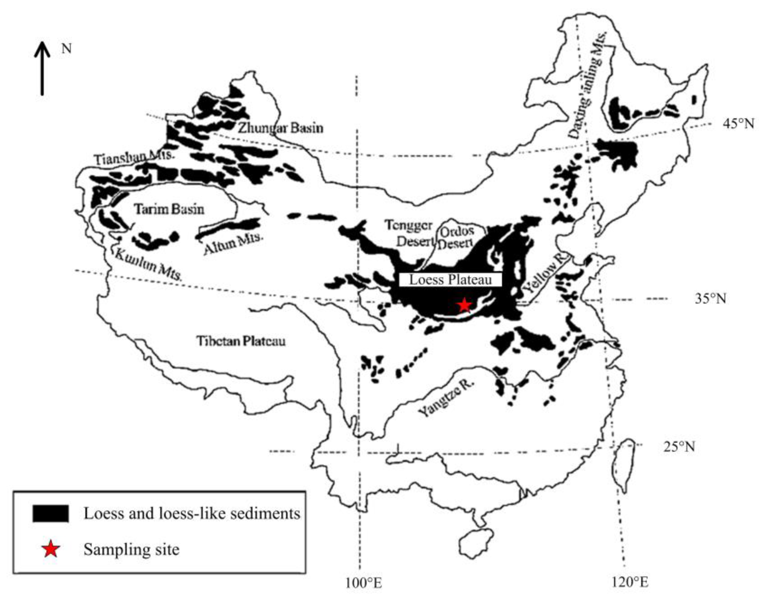
The materials utilized in the current research included loess soil, NM, and distilled water (Figure 1). The loess soil was collected from a depth of 2.0~2.5 m beneath the ground of a high-speed rail construction site in Xi’an, China (Figure 2). It was mustard yellow in color and was classified as low-plasticity clay (CL) according to the unified classification system. Table 1 lists the physical properties determined as per ASTM D422-63, D854, and D4318 [39,40,41]. The mineral components based on the X-ray diffractometer test were also provided. The NM material was a white, nano-scale, high-purity MgO powder procured from a firm in Guangzhou, Guangdong Province, China. The physical and chemical properties are presented in Table 2.

2.2. Consistency Limits and Compaction Test

According to trial tests and previous studies, the NM content ( C NM ) was selected as 0%, 1%, 2%, 3%, and 4% (on dry weight basis). To prepare the NM–loess mixture, the air-dried loess was first grinded and passed through the 0.5 mm sieve, and then oven-dried with NM powder at 105 °C for 24 h. To produce a homogeneous mixture, the loess was first divided into small quantities and preliminarily mixed with a pre-specified amount of NM. Then, the small portions were combined and manually stirred until uniformity was ensured. After the mixture preparation and humectation (24 h), the standard compaction test (SCT) and consistency limits test (CLT) for all NM content were performed, following ASTM D4318 and D1557-12 [41,43]. Accordingly, the optimum water content (wopt), maximum dry density ( ρ dmax ), plastic limit (PL), and liquid limit (LL) were determined for varying NM dosages.

2.3. Unconfined Compression Test

For engineering practice, the samples for the unconfined compression test (UCT) were prepared with the wopt and ρ dmax for corresponding NM dosages. Table 3 presented the mixing design and corresponding test items. To prepare these samples, the homogenous NM–loess mixture with predetermined moisture was packed in a 38 × 76 mm cylindrical mold in three layers. Before subsequent compaction, each layer’s surface was scraped to avoid the delamination effect. After being removed from the mold, the specimen was sealed with two layers of plastic film for constant moisture and then stored in a curing chamber under a constant temperature of 20 °C for 1, 7, 14, 28, and 42 days. For performing UCT, a strain-controlled YYW-2 unconfined compression apparatus (Nanjing Soil Instrument Company, Nanjing, China) was utilized (Figure 1). According to ASTM D2166 [44], the strain rate was selected as 1 mm/min and continued until a complete stress–strain response was achieved. Afterwards, some key mechanical parameters, including UCS, deformation modulus, and the strain at failure, could be determined.

2.4. Nuclear Magnetic Resonance Test

NMR is a non-destructive testing method that can be utilized to determine the state of water in unsaturated soils. In the T2 spectrum, the relaxation time is inversely proportional to the surface tension, which is further related to the water state [45,46]. Thus, a clear idea about the bound-water and free-water could be obtained by analyzing the T2 spectrum. In the present work, the equipment to realize NMR measurements was a 30 MHz Low-field (0.3 T) NMR spectrometer manufactured by Suzhou Niumag Analytical Instrument Corporation (Figure 1). Two groups of samples (T26~T30 and T31~T35) were prepared to reveal the effects of NM and curing, respectively. One group was cured by 28 days with varying NM contents from 0% to 4%; the other group was with 2% NM content and varying curing times. All the samples were prepared at a constant moisture of 18.4% and a dry density of 1.61 g/cm3 (the wopt and ρ dmax for the 2% NM case).

3. Results and Discussion

3.1. Consistency Limits

Figure 3 illustrates the variations of the plastic limit (PL), liquid limit (LL), and plasticity index (PI) with the addition of NM. Generally, both LL and PL increased with the addition of NM. The growth of PL was more remarkable than that of LL, therefore, resulting in a decreasing trend of PI with increasing NM. Specifically, as NM increased from 0% to 4%, PL and LL increased by 40.00% and 10.53%, respectively, while the corresponding PI decreased by 33.58%. This phenomenon suggested improved water-absorption ability, which could be attributed to the great specific surface area (SSA) and surface charge of NM particles. However, the reduction in PI with increasing fine-grained additives is interesting, but common in the design of stabilized soils [31,47]. In such situations, the decrease of PI is not due to the reduction of LL, but rather the comparatively higher growth of PL than that of LL.

3.2. Compactability

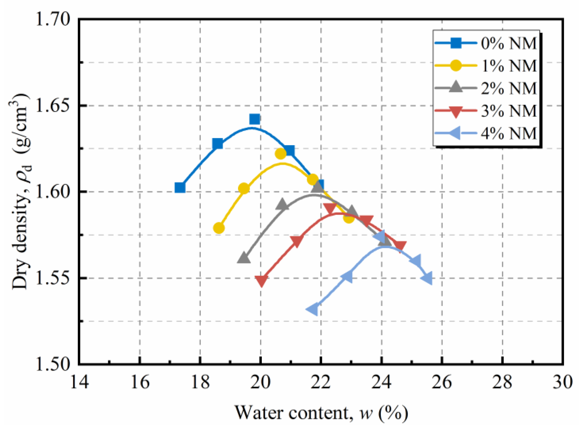
Figure 4 illustrates the standard compaction data of loess treated with 0%, 1%, 2%, 3%, and 4% NM. It can be seen that adding NM from 0% to 4% led to an increase in wopt from 19.8% to 23.9%, yet a decrease in ρ dmax from 1.64 g/cm3 to 1.57 g/cm3. Similar observations were also reported in previous works on soils treated with fine-grained stabilizer [31,48]. The increase in wopt was probably due to the excellent water-absorption capacity of NM [49,50], and the change-down in ρ dmax could be attributed to the following reasons: (1) NM particles having thicker bound-water films and lower specific gravity compared with that of soil particles; (2) the increased interparticle bonding force by adding NM, which prevented easy compaction. Therefore, the more the NM was added, the higher the wopt was, and the lower the ρ dmax was.

3.3. Mechanical Properties

3.3.1. Stress–Strain Behavior

Figure 5 presented the stress–strain response of NM-treated loess with varying NM contents and curing times. As NM content grew, the improvement in peak-strength was evident when NM content was lower than 2%. Yet, with further NM addition, a considerable drop in peak-strength was observed. For all cases, the peak-strength achieved its maximum at NM content of 2%. Moreover, the improving effect of NM was enhanced with increasing curing time; that is, the 2% NM content combined with 42 days of curing gave the best improving effect.
The shapes of stress–strain curves varied wildly with NM content. For the cases of natural loess, ductile behavior was manifested, with a gentle rise and mild decline of stress, respectively, in the pre- and post-peak phase. With the addition of NM (≤2%), both the peak-strength and growth rate rose, and the post-peak drop in stress became increasingly pronounced. In addition, the strain corresponding to peak-stress, ε f , decreased gently with the addition of NM. As a result, the NM-treated samples exhibited much more brittle behavior than the untreated one. However, it was also found that excessive NM addition (>2.0%) would lead to declines in both strength and brittleness. As for the effects of curing, the longer the curing time was, the more brittleness the sample exhibited. Yet, the effects of curing on brittleness were less significant than that of NM.

3.3.2. Unconfined Compressive Strength

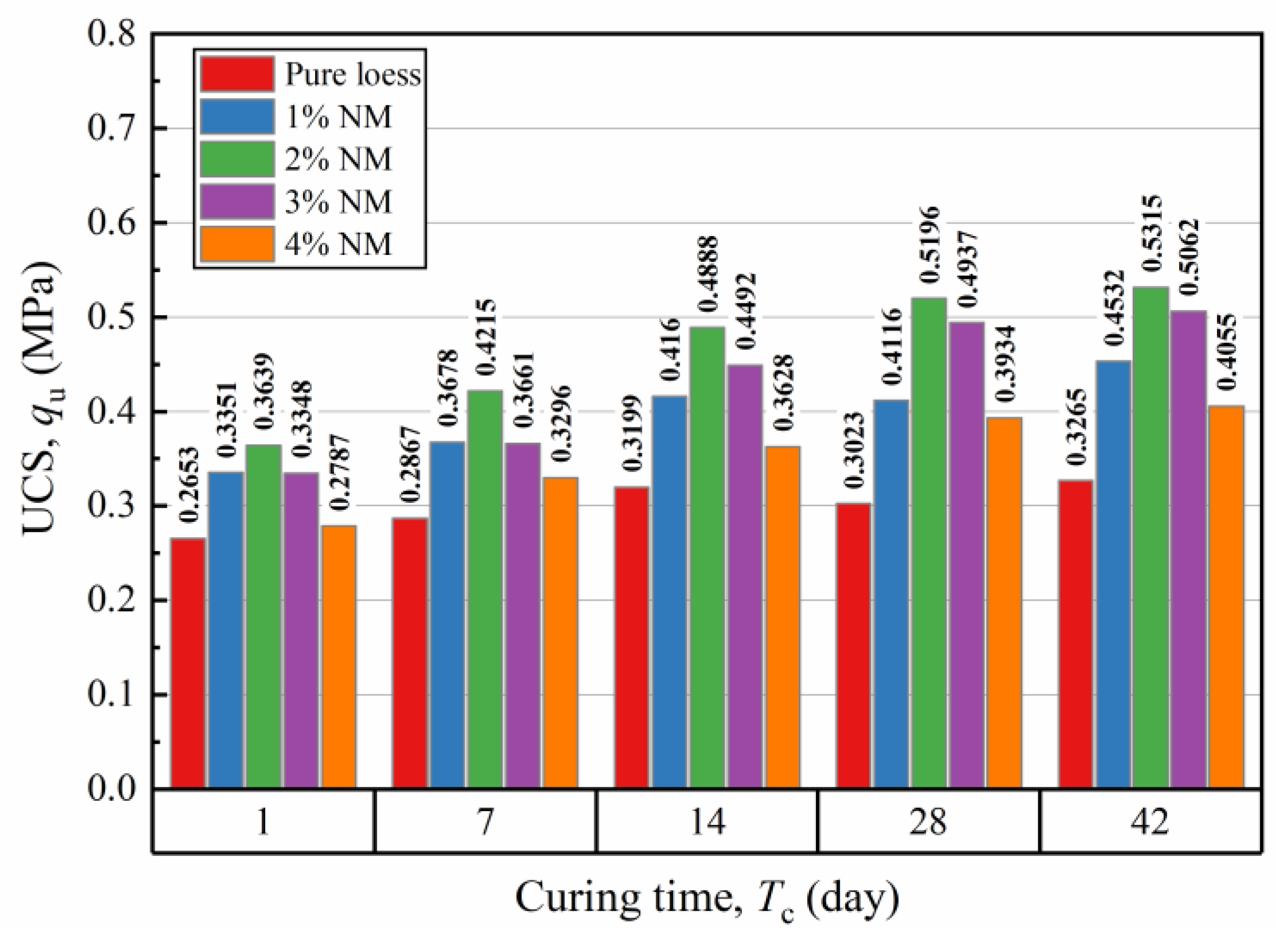
The contributions of NM content ( C NM ) and curing time ( T c ) to variations in UCS ( q u ) are illustrated in Figure 6. As expected, increasing the curing time considerably improved the UCS of NM-treated loess. For NM-treated loess, the gain in UCS was drastic in the early 28 days, and thereafter, it became less prominent as the average increment in q u with T c from 28 to 42 was just by 3.8%. So, for NM-treated loess, experiencing 28 days of curing is recommended. In this condition, the q u of 0%, 1%, 2%, 3%, and 4% NM cases increased by 14.0%, 22.8%, 42.7%, 47.4%, and 41.1%, respectively, compared with the corresponding 1-day cured cases. It is noteworthy that, for NM-treated samples, the curing-induced growth in q u was up to 47.4%, which was 2.386 times higher than that of the untreated one (14.0%). This indicated the strong strength growth potential of NM-treated loess after an appropriate length of curing. Generally, the improving effects of curing can be interpreted by the thixotropy effect resulting from bound-water structure change and chemical and electrical transport during the curing period [51].
The effect of NM on UCS is also observed in Figure 6. In all cases, the UCS followed a “rise-fall” path with the addition of NM, reaching its maximum at 2% NM content. To be specific, at 28 days of curing, NM-treated samples of 1%, 2%, 3%, and 4% attained UCS values of 0.4116, 0.5196, 0.4937, and 0.3934 MPa, respectively, which is 36.14%, 71.83%, 63.28%, and 30.09% higher, respectively, than that of the untreated one (0.3023 MPa). So, about 72% UCS gain was to be expected with 2% NM addition and 28 days of curing, which was suggested in engineering practice. On the other hand, it is interesting to note that adding more than 2% NM had an adverse effect on UCS. This undesirable impact of adding excessive nano-materials were also identified in previous investigations on soil stabilization [23,31,36,52].
As discussed above, the NM content C NM and curing time T c were two crucial factors controlling the UCS of NM-treated loess. In this part, the following function was attempted to describe the relationship between UCS and these factors:
q u = q u - 0 - 1 a 1 C NM 2 + b 1 C NM + 1 / b 2 × a 2 ln T c + b 2
where q u , C NM , and T c was expressed in MPa, %, and day, respectively; a and b were the regression coefficients; and the subscript 1 and 2 indicated affected by C NM and T c , respectively. q u - 0 - 1 was the estimated q u value for the 0% NM and 1 day-cured condition.
In Equation (1), the q u of NM-treated loess included three parts: the standard UCS of untreated loess represented by q u - 0 - 1 , the contribution of NM exhibited by a quadratic function, and the contribution of curing time presented by a logarithmic function. The parameters in this equation were determined from data fitting, i.e., q u - 0 - 1 = 0.2312 , a 1 = 1.641 , b 1 = 7.244 , a 2 = 8.837 × 10 3 , and b 2 = 6.672 × 10 2 . Figure 7 illustrates the fitting results compared with the experimental data. It shows that the predicted results matched the experimental data well, achieving a fine determination coefficient of 0.906, which indicates that Equation (1) can be confidently used in determining the UCS of NM-treated loess.

3.3.3. Strain at Failure

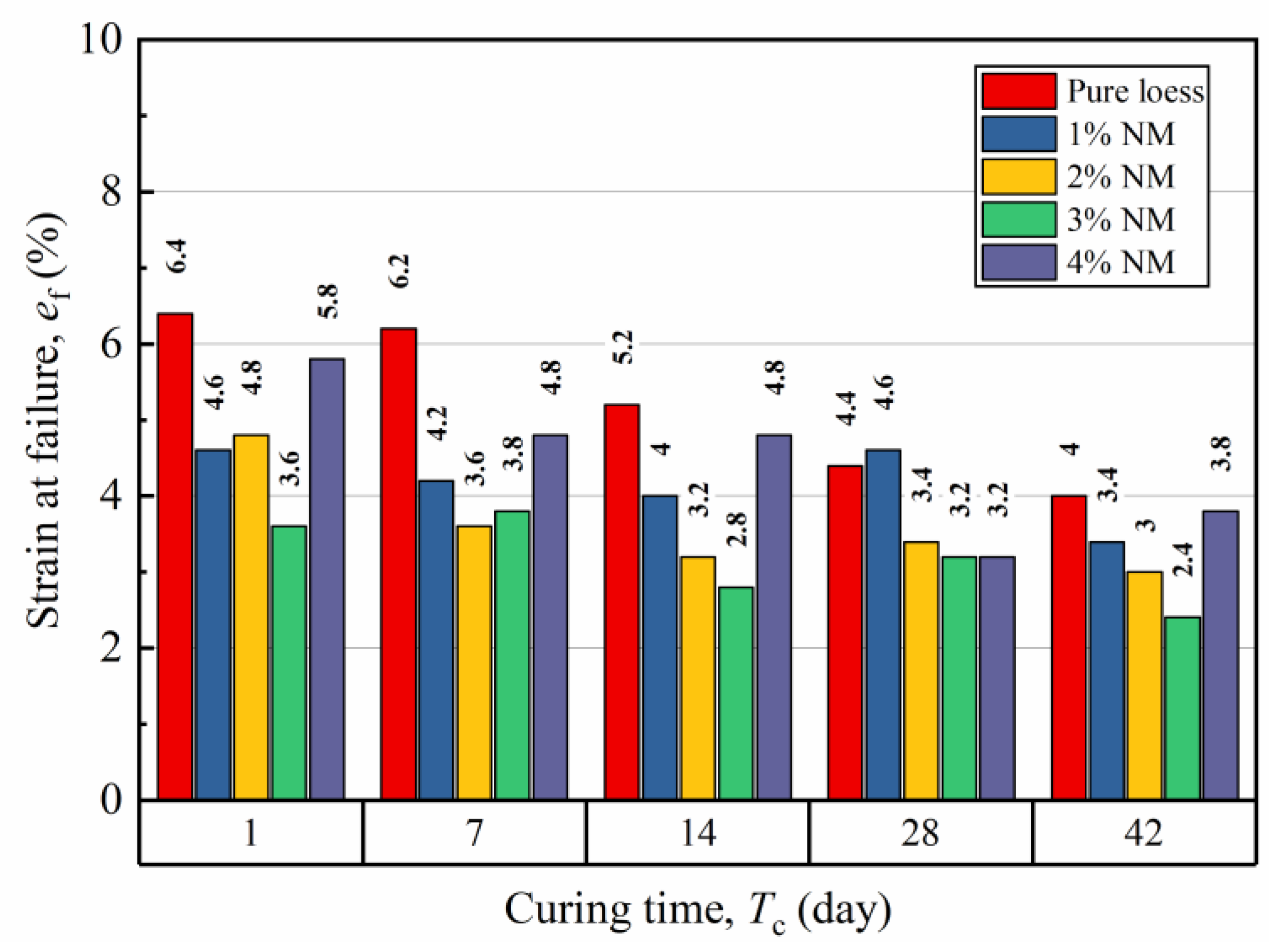
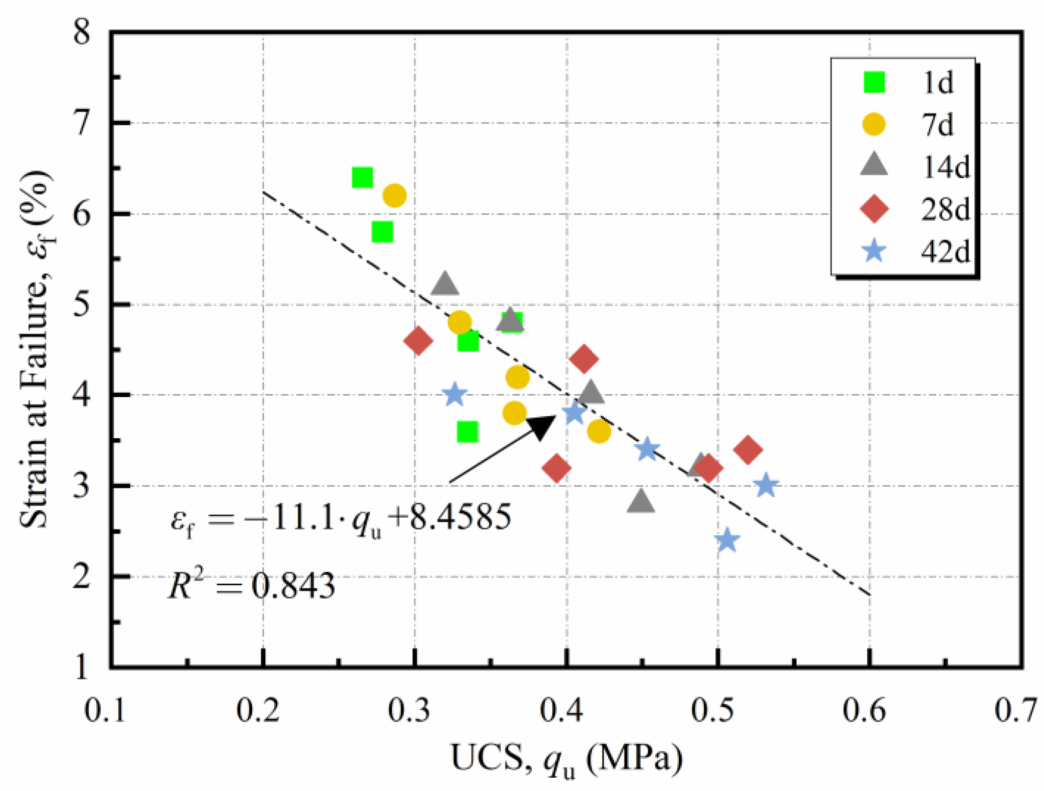
Figure 8 presents the strain at failure ε f with various NM contents and curing times. It was observed that most ε f -values distributed in the range of 2.4% to 6.4%. Adding NM to the natural loess led to a decline in ε f at low NM levels (≤2%). Thereafter, with further NM addition, an ascending trend of ε f was observed. Meanwhile, ε f generally decreased with increasing curing time. In this way, ε f reached its minimum (2.4%) at 3% NM content and 42 days of curing. It is noteworthy that the changing tendency of ε f was just the opposite of the trend of q u , indicating a probable correlation between them.
Figure 9 presents the trend of ε f with q u for NM-treated loess. Generally, ε f presented an approximately linear correlation with q u . With a regression analysis, the ε f - q u relationship was well expressed by the following linear function:
ε f = κ q u + ζ ,
where ε f and q u were respectively expressed in % and MPa. κ and ζ were empirical constants equal to −11.1 and 8.4585, respectively. The fair determination coefficient, R 2 = 0.843 , indicated that Equation (2) could be utilized in characterizing the correlation between ε f and q u . Furthermore, the fair fitting results also suggested that the ε f q u relation of NM-treated loess was not sensitive to NM and curing, which brought convenience in engineering application.
Figure 10 exhibits the data of nano-SiO2 (NS)- and nano-MgO (NM)-treated clays extracted from the literature [22,31,37,53]. Twelve pairs of ε f and q u were fitted according to Equation (2), and the fitting results are exhibited in this figure. It was observed that ε f changed with q u as a linear function in almost every case. The higher determination coefficient, R2, indicated the linear expression may be suitable to describe the ε f q u relationship of nanomaterial-treated soils. Notably, the parameter κ was negative for the cases where only NS or NM and cement were added. It was consistent with the observation of NM-treated loess in this work. However, as fibers were added, it was interesting to note that the parameter κ turned positive. It indicated that adding fiber impacted not only on the strength, but also on the ε f q u relationship. This phenomenon might be attributed to the good ductility of fiber-treated soil, which endowed them with larger failure strain and corresponding higher UCS. In terms of ζ , it is positive in most cases, just the same as the results in this work. This is in accordance with the theoretical analysis, because UCS cannot be reached at 0% strain. For the cases of Ahmadi et al., the presence of negative ζ value indicated the obtained expression was not applicable in the lower UCS level.

3.3.4. Deformation Modulus

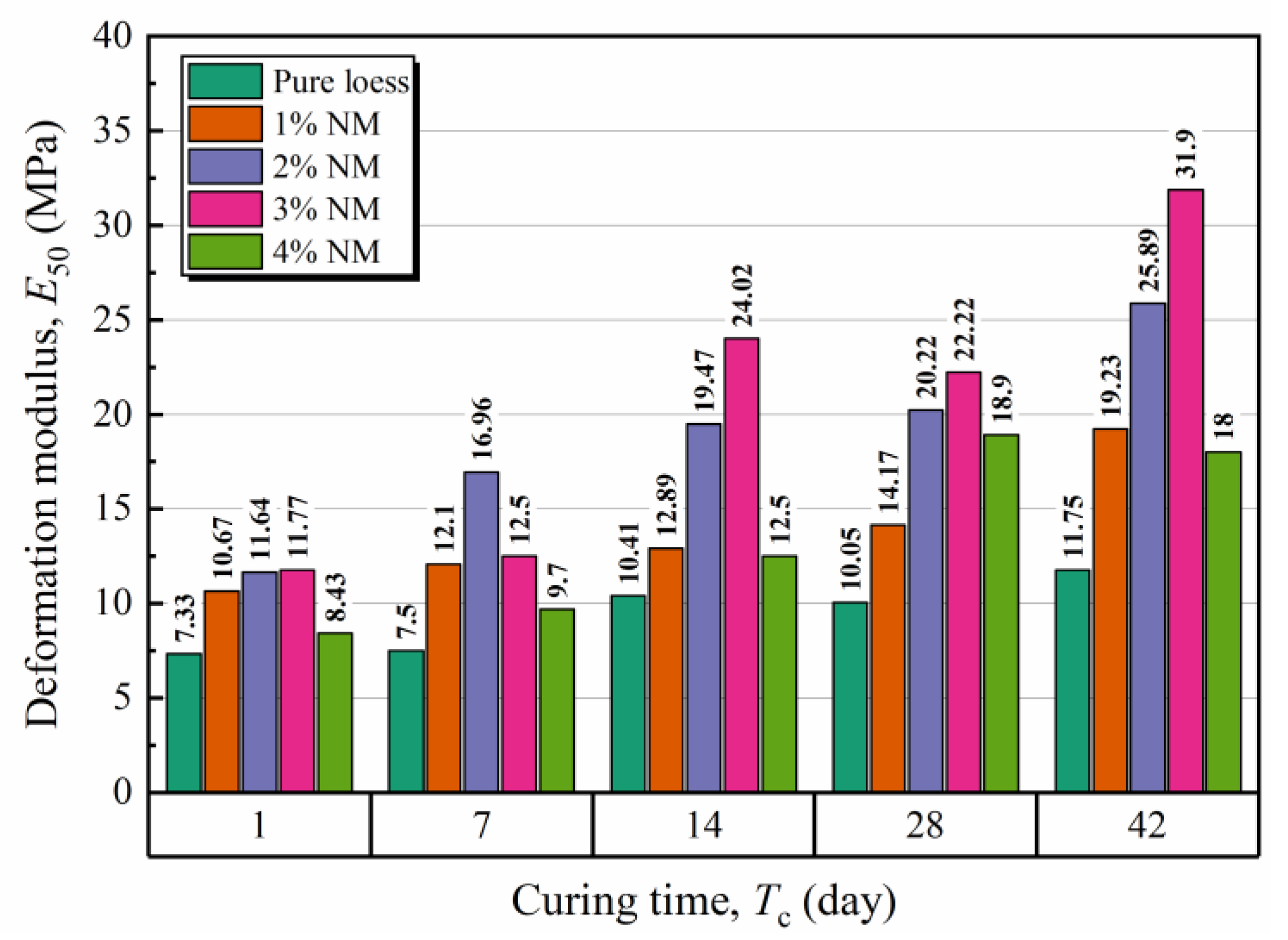
As previously discussed, the NM-treated loess exhibited elastic–plastic behavior like most geo-materials. Normally, this behavior can be described by the deformation modulus, E 50 , which is expressed as the ratio of stress to strain when the strain is at half of ε f . Figure 11 illustrated the effects of NM and curing on the deformation modulus. Generally, the deformation modulus of NM-treated loess was in the range of 7.33 to 31.9 MPa. It presented a rising tendency with increasing curing time and a “rise-fall” tendency with the addition of NM. Notably, these tendencies were similar to that of UCS in Figure 6, which indicated a probable link between E 50 and q u .
Through reviewing existing research, the E 50 q u relationship was generally described by a simple linear function, i.e., E 50 = η q u . Here, η was a fitting parameter, and diverse ranges of η have been provided for various cement-treated clays [54,55,56]. As for NM-treated loess, Figure 12 exhibited the variation of E 50 versus q u of samples at various test conditions. It demonstrated that the E 50 of NM-treated loess was proportional to q u , but in a nonzero-intercept way. Therefore, their relationship could be described as,
E 50 = η q u + β
where both E 50 and q u were expressed in MPa. The regression analysis yielded η = 72.0 and β = 12.813 with R 2 = 0.818 . It is noteworthy that the intercept β for NM-treated loess was negative, unlike the traditional zero-intercept model for cement-treated clays. This was probably due to the relatively weak strength and high ductility of the bonding force formed by NM, compared with that formed by cement. Consequently, the NM-treated loess exhibited high strength under relatively low stiffness, resulting in the negative intercept β .
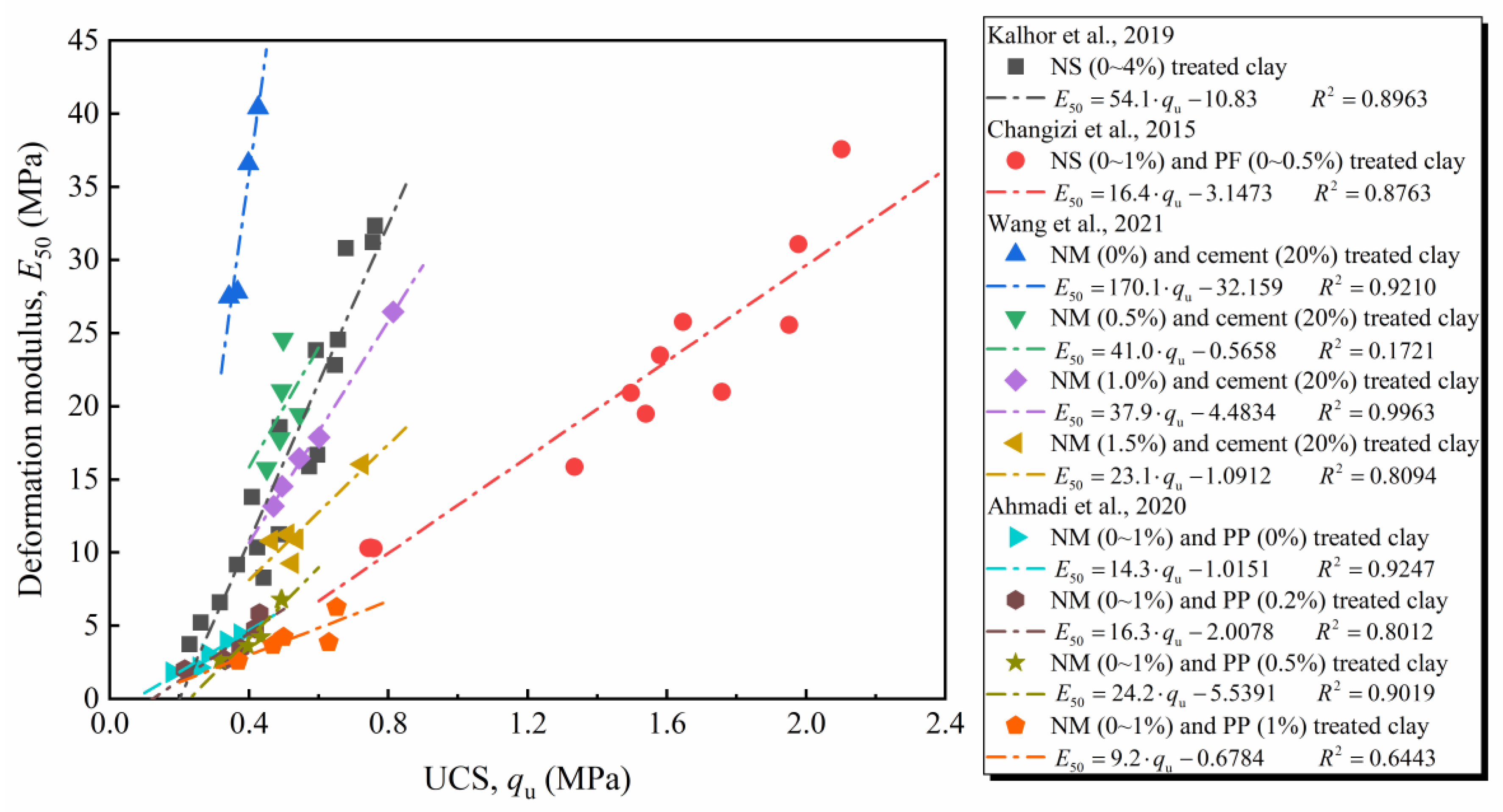
Figure 13 presents the E 50 q u relationships of nanomaterial-stabilized clays extracted from literature [22,31,37,53]. Based on Equation (3), information about the parameters η and β could be obtained together with the determination coefficient R 2 : (1) For the NS (0~4%) stabilized clay with E 50 of 3~38 MPa and q u of 0.4~2.1 MPa, the fitting parameter η and β were 54.1 and −10.83, respectively; (2) For the clay treated with NS (0~1%) and polyester fiber (PF) (0~0.5%), the η and β were considered to be 16.4 and −3.1473, respectively; (3) for the NM (0~1.5%) and cement (20%) treated clay, the η was in a range of 23.1~170.1, and β was in a range of −0.5658~−32.159; (4) for NM (0~1%) and polypropylene fiber (PP) (0~1%) treated clay, the parameters η of 9.2~16.3 and β of −0.6784~−5.5391 were determined. For most cases, the resulting R 2 -values are quite high, suggesting that the proposed equation was also applicable for other nanomaterial-treated soils. Furthermore, it is noteworthy that the fitting parameter β was negative and η was positive for all cases. This was consistent with the results of this work, indicating it might be a common phenomenon in nanomaterial-based stabilization techniques.

3.4. Stabilization Mechanism

3.4.1. Effect of Nano-MgO

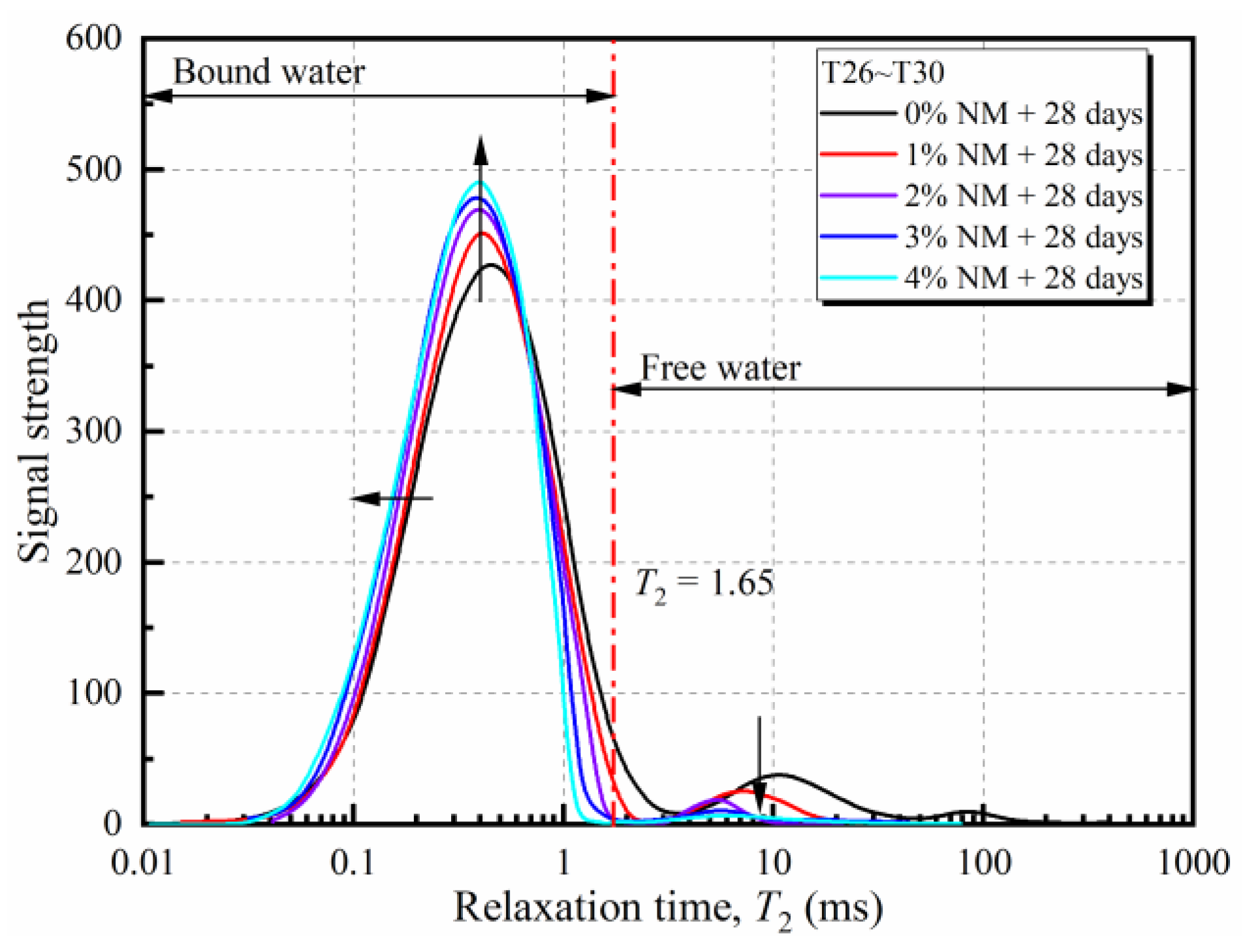
Figure 14 depicts the T2 spectra of NM-treated loess with varying NM dosages. Since the relaxation time is inversely proportional to the surface tension, the T2 spectrum curve could be used to reflect the states of water in soil samples. According to He et al. [57], for loess soil, the cutoff T2 value corresponding to bound-water and free-water was at 1.65 ms (red line). That is, the left/right side area under the T2 curve reflected the amount of bound-/free-water, respectively. As exhibited in Figure 14, the curves for all cases could be roughly divided into two peaks, P1 and P2, which were respectively located in the left side and right side of the red line. Notably, the left side peak P1 was dominating, which denoted that most of the water contained in the soil belonged to bound-water. An increase in NM content led to an increase in P1, yet a decrease in P2. The left-shift of the T2 curve with the addition of NM was also noticed. The above phenomena indicated the rising share of bound-water with increasing NM and curing. It could be attributed to the excellent surface effect and hydrophilicity of MgO nano-particles, which attracted more water molecules to make the proportion of bound-water enhanced [58].
Based on the above discussion and literature review, the improving mechanism of NM was primarily due to the water-absorbing and cementing effect of NM. As for the water-absorbing effect, part of the free-water transforming to bound-water would lead to a rise in the internal friction angle and a decline in the interparticle cohesion of loess soil at a given water content [59]. However, the cementing effect mainly enhanced the interparticle cohesion. In view of the unconfined compression test condition, the UCS and deformation modulus of the soil depended more on the cohesion than on the internal friction angle. Therefore, as the NM content increased, the UCS and modulus presented a rising trend when the NM dosage was small (less than 2%), because, in this condition, the improvement in cohesion induced by the cementing effects was dominating. However, as the NM content was larger than 2%, the unfavorable effects of water-absorbing became evident, resulting in the decline of cohesion and further decreasing of the UCS and deformation modulus.

3.4.2. Effects of Curing Time

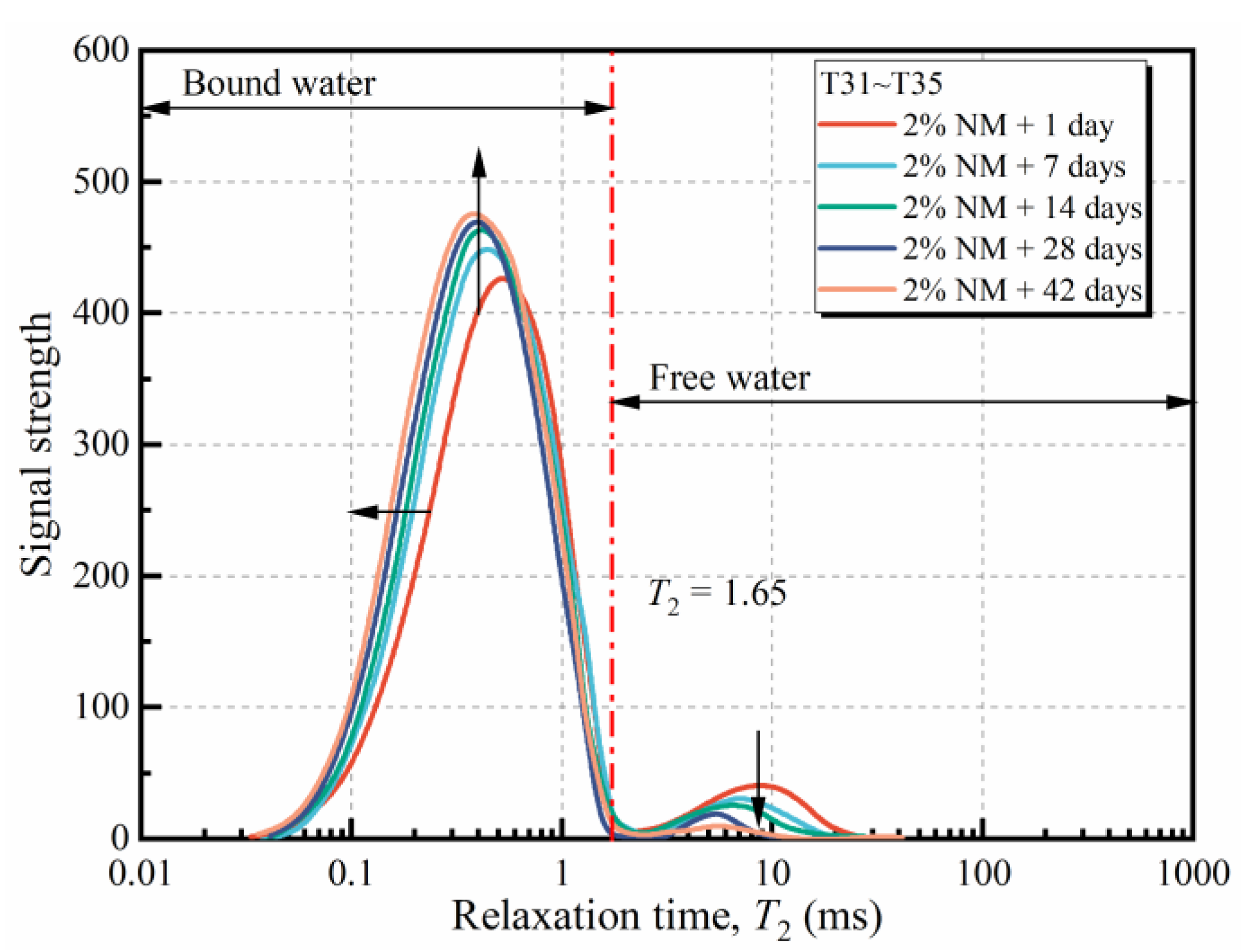
The T2 curves of samples with 2% NM at varying curing periods are plotted in Figure 15. Similarly, the samples mainly consisted of two peaks, P1 and P2. With increasing curing time, the T2 curve shifted towards a higher signal in P1 and a lower signal in P2. Further, the left shift towards lower relaxation time was also observed. The above phenomena suggested the water transformation from free-water to bound-water with curing. It indicated a moisture redistribution procedure, which was resulting from the comparatively strong absorbability of NM than that of soil particles. This is part of the reason for the improving effects of curing on the mechanical properties of NM-treated loess. Another reason is that the cementing effect of NM could be enhanced with curing. Thus, the UCS and deformation modulus increased with curing time. Moreover, it was found that the variation of the T2 curve during the curing period was evident at the early 14 days and became not obvious after 28 days of curing. This was in accordance with the results obtained by the unconfined compression test.

4. Conclusions

This paper investigated the geotechnical properties and water-state evolution of loess with varying NM content and curing times. The UCS, strain at failure, and deformation modulus of NM-treated loess were quantitively analyzed. In addition, the improving mechanisms of NM and curing were unfolded from the aspect of water-state changes. The main findings can be summarized as follows:
  • Adding NM to loess soil led to increases in the plastic limit (from 20.5% to 28.7%), liquid limit (from 34.2% to 37.8%), and optimum water content (from 19.8% to 23.9%), but declines in the plasticity index (from 13.7% to 9.1%) and maximum dry density (from 1.64 g/cm3 to 1.57 g/cm3).
  • NM and curing were two crucial factors influencing the mechanical properties of NM-treated loess. The improvement in UCS with curing was evident in the early 28 days and became insignificant thereafter. As NM content increased, the UCS followed a “rise-fall” path (from about 0.3023 to 0.5196 to 0.3934 MPa for 28d curing), indicating an optimum NM dosage at 2%. So, 2% NM-treated loess with 28 days of curing is accordingly suggested, and about 72% UCS gain is to be expected in this condition.
  • The strain at failure decreased at first and then increased with the addition of NM. However, the deformation modulus presented an opposite trend. Both of them exhibited a linear relationship with UCS. Empirical models for them were established and validated by literature data.
  • The stabilizing mechanism of NM-treated loess was explored from the aspect of water-state change. The enhancement of mechanical properties primarily was due to the water-absorbing and cementing effects of NM. The former caused water transformation from free-water to bound-water inside the soil and enhanced the interparticle cohesion as potently as the cementing effect did.

Author Contributions

Conceptualization, S.C.; methodology, S.C.; validation, P.N.; formal analysis, S.C.; investigation, Z.S.; data curation, P.N.; writing—original draft preparation, S.C.; writing—review and editing, K.Y.; project administration, S.C.; funding acquisition, S.C. All authors have read and agreed to the published version of the manuscript.

Funding

This research is supported by the National Natural Science Foundation of China (No. 12102367); the Natural Science Basic Research Program of Shaanxi (No. 2020JM-642, No. 2021JQ-870), and the Special research project of the Education Department of Shaanxi Provincial Government (No. 21JK0961).

Institutional Review Board Statement

Not applicable.

Informed Consent Statement

Not applicable.

Data Availability Statement

The data presented in this study are available on request from the corresponding author.

Acknowledgments

The Youth Innovation Team of Shaanxi Universities is acknowledged.

Conflicts of Interest

The authors declare no conflict of interest.

References

  1. Xue, Z.F.; Cheng, W.C.; Wang, L.; Song, G. Improvement of the shearing behavior of loess using recycled straw fiber reinforcement. KSCE J. Civ. Eng. 2021, 25, 3319–3335. [Google Scholar] [CrossRef]
  2. Li, Y.; Shi, W.; Aydin, A.; Beroya-Eitner, M.A.; Gao, G. Loess genesis and worldwide distribution. Earth-Sci. Rev. 2020, 201, 102947. [Google Scholar] [CrossRef]
  3. Wang, S.L.; Lv, Q.F.; Baaj, H.; Li, X.Y.; Zhao, Y.X. Volume change behavior and microstructure of stabilized loess under cyclic freeze-thaw conditions. Can. J. Civ. Eng. 2016, 43, 865–874. [Google Scholar] [CrossRef] [Green Version]
  4. Jia, L.; Guo, J.; Zhou, Z.; Fu, Y.; Yao, K. Experimental investigation on strength development of lime stabilized loess. RSC Adv. 2019, 9, 19680–19689. [Google Scholar] [CrossRef] [Green Version]
  5. Mariri, M.; Moayed, R.Z.; Kordnaeij, A. Stress-strain behavior of loess soil stabilized with cement, zeolite, and recycled polyester fiber. J. Mater. Civ. Eng. 2019, 31, 04019291. [Google Scholar] [CrossRef]
  6. Yan, C.; Zhang, Z.; Jing, Y. Characteristics of strength and pore distribution of lime-fly ash loess under freeze-thaw cycles and dry-wet cycles. Arab. J. Geosci. 2017, 10, 544. [Google Scholar] [CrossRef]
  7. Zhang, Y.; Johnson, A.E.; White, D.J. Freeze-thaw performance of cement and fly ash stabilized loess. Transp. Geotech. 2019, 21, 100279. [Google Scholar] [CrossRef]
  8. Benhelal, E.; Zahedi, G.; Shamsaei, E.; Bahadori, A. Global strategies and potentials to curb CO2 emissions in cement industry. J. Clean Prod. 2013, 51, 142–161. [Google Scholar] [CrossRef]
  9. Kannan, G.; Sujatha, E.R. A review on the choice of nano-silica as soil stabilizer. Silicon 2022, 14, 6477–6492. [Google Scholar] [CrossRef]
  10. Arulrajah, A.; Mohammadinia, A.; Phummiphan, I.; Horpibulsuk, S.; Samingthong, W. Stabilization of recycled demolition aggregates by geopolymers comprising calcium carbide residue, fly ash and slag precursors. Constr. Build. Mater. 2016, 114, 864–873. [Google Scholar] [CrossRef]
  11. Cabalar, A.F.; Ismael, I.A.; Yavuz, A. Use of zinc coated steel CNC milling waste for road pavement subgrade. Transp. Geotech. 2020, 23, 100342. [Google Scholar] [CrossRef]
  12. Jo, B.W.; Kim, C.H.; Tae, G.H.; Park, J.B. Characteristics of cement mortar with nano-SiO2 particles. Constr. Build. Mater. 2007, 21, 1351–1355. [Google Scholar] [CrossRef]
  13. Hanus, M.J.; Harris, A.T. Nanotechnology innovations for the construction industry. Prog. Mater. Sci. 2013, 58, 1056–1102. [Google Scholar] [CrossRef]
  14. Krishnan, J.; Shukla, S. The behavior of soil stabilized with nanoparticles: An extensive review of the present status and its applications. Arab. J. Geosci. 2019, 12, 436. [Google Scholar] [CrossRef]
  15. Zhang, G. Soil nanoparticles and their influence on engineering properties of soils. In Proceedings of the Geo-Denver 2007, Denver, CO, USA, 18–21 February 2007; pp. 1–13. [Google Scholar] [CrossRef]
  16. Huang, Y.; Wang, L. Experimental studies on nanomaterials for soil improvement: A review. Environ. Earth Sci. 2016, 75, 497. [Google Scholar] [CrossRef]
  17. Ghasabkolaei, N.; Janalizadeh Choobbasti, A.; Roshan, N.; Ghasemi, S.E. Geotechnical properties of the soils modified with nanomaterials: A comprehensive review. Arch. Civ. Mech. Eng. 2017, 17, 639–650. [Google Scholar] [CrossRef]
  18. Changizi, F.; Haddad, A. Improving the geotechnical properties of soft clay with nano-silica particles. Proc. Inst. Civ. Eng.-Ground Improv. 2017, 170, 62–71. [Google Scholar] [CrossRef]
  19. Sarli, J.M.; Hadadi, F.; Bagheri, R.A. Stabilizing geotechnical properties of loess soil by mixing recycled polyester fiber and nano-SiO2. Geotech. Geol. Eng. 2020, 38, 1151–1163. [Google Scholar] [CrossRef]
  20. Mohammadi, M.; Niazian, M. Investigation of nano-clay effect on geotechnical properties of Rasht clay. Int. J. Adv. Sci. Tech. Res. 2013, 3, 37–46. Available online: http://refhub.elsevier.com/S0950-0618(17)31918-9/h0405 (accessed on 17 February 2023).
  21. Taha, M.R.; Taha, O.M.E. Influence of nano-material on the expansive and shrinkage soil behavior. J. Nanopart. Res. 2012, 14, 1190. [Google Scholar] [CrossRef]
  22. Wang, W.; Zhou, H.; Li, J.; Tao, F.; Li, C.; Qian, B.; Jiang, P. Influence of carbonization process on the mechanical properties of nano-MgO modified cement soil. Sustainability 2021, 13, 3558. [Google Scholar] [CrossRef]
  23. Yao, K.; Wang, W.; Li, N.; Zhang, C.; Wang, L. Investigation on strength and microstructure characteristics of nano-MgO admixed with cemented soft soil. Constr. Build. Mater. 2019, 206, 160–168. [Google Scholar] [CrossRef]
  24. Choobbasti, A.J.; Samakoosh, M.A.; Kutanaei, S.S. Mechanical properties soil stabilized with nano calcium carbonate and reinforced with carpet waste fibers. Constr. Build. Mater. 2019, 211, 1094–1104. [Google Scholar] [CrossRef]
  25. Mohammadi, M.; Rajabi, A.M.; Khodaparast, M. Experimental and numerical evaluation of the effect of nano calcium carbonate on geotechnical properties of clayey sand soil. KSCE J. Civ. Eng. 2022, 26, 35–46. [Google Scholar] [CrossRef]
  26. Meyer, C. The greening of the concrete industry. Cem. Concr. Comp. 2009, 31, 601–605. [Google Scholar] [CrossRef]
  27. Wang, D.X.; Wang, H.W.; Wang, X.Q. Compressibility and strength behavior of marine soils solidified with MgO-A green and low carbon binder. Mar. Georesour. Geotechnol. 2017, 35, 878–886. [Google Scholar] [CrossRef]
  28. Gu, K.; Jin, F.; Al-Tabbaa, A.; Shi, B.; Liu, C.; Gao, L. Incorporation of reactive magnesia and quicklime in sustainable binders for soil stabilization. Eng. Geol. 2015, 195, 53–62. [Google Scholar] [CrossRef]
  29. Gao, L.; Ren, K.; Ren, Z.; Yu, X. Study on the shear property of nano-MgO-modified soil. Mar. Georesour. Geotechnol. 2018, 36, 465–470. [Google Scholar] [CrossRef]
  30. Majeed, Z.H.; Taha, M.R. Effect of nanomaterial treatment on geotechnical properties of a Penang soft soil. J. Asian Sci. Res. 2012, 2, 587–592. [Google Scholar]
  31. Kalhor, A.; Ghazavi, M.; Roustaei, M.; Mirhosseini, S.M. Influence of nano-SiO2 on geotechnical properties of fine soils subjected to freeze-thaw cycles. Cold Reg. Sci. Technol. 2019, 161, 129–136. [Google Scholar] [CrossRef]
  32. Sharo, A.A.; Alawneh, A.S. Enhancement of the strength and swelling characteristics of expansive clayey soil using nano-clay material. In Proceedings of the Geo-Chicago 2016, Chicago, IL, USA, 14–18 August 2016; pp. 451–457. [Google Scholar] [CrossRef]
  33. Chen, S.; Hou, X.; Luo, T.; Yu, Y.; Jin, L. Effects of MgO nanoparticles on dynamic shear modulus of loess subjected to freeze-thaw cycles. J. Mater. Res. Technol. 2022, 18, 5019–5031. [Google Scholar] [CrossRef]
  34. Gao, L.; Ren, Z.; Yu, X. Experimental study of nanometer magnesium oxide-modified clay. Soil Mech. Found. Eng. 2015, 52, 218–224. [Google Scholar] [CrossRef]
  35. Majeed, Z.H.; Taha, M.R. A review of stabilization of soils by using nanomaterials. Aust. J. Basic. Appl. Sci. 2013, 7, 576–581. [Google Scholar]
  36. Govindasamy, P.; Taha, M.R.; Alsharef, J.; Ramalingam, K. Influence of nanolime and curing period on unconfined compressive strength of soil. Appl. Environ. Soil Sci. 2017, 2017, 8307493. [Google Scholar] [CrossRef] [Green Version]
  37. Ahmadi, H.; Janati, S.; Jamshidi Chenari, R. Strength parameters of stabilized clay using polypropylene fibers and nano-MgO: An experimental study. Geotech. Geol. Eng. 2020, 38, 2845–2858. [Google Scholar] [CrossRef]
  38. Cao, G. Nanostructures and Nanomaterials-Synthesis, Properties and Applications; Imperial College Press: London, UK, 2004. [Google Scholar]
  39. ASTM D422-63; Standard Test Method for Particle-Size Analysis of Soils. ASTM: West Conshohocken, PA, USA, 2007.
  40. ASTM D854; Standard Test Methods for Specific Gravity of Soil Solids by Water Pycnometer. ASTM: West Conshohocken, PA, USA, 2010.
  41. ASTM D4318; Standard Test Methods for Liquid Limit, Plastic Limit, and Plasticity Index of Soils. ASTM: West Conshohocken, PA, USA, 2012.
  42. Li, G.; Wang, F.; Ma, W.; Fortier, R.; Mu, Y.; Mao, Y.; Hou, X. Variations in strength and deformation of compacted loess exposed to wetting-drying and freeze-thaw cycles. Cold Reg. Sci. Technol. 2018, 151, 159–167. [Google Scholar] [CrossRef]
  43. ASTM D1557-12; Standard Test Methods for Laboratory Compaction Characteristics of Soil Using Modified Effort. ASTM: West Conshohocken, PA, USA, 2021.
  44. ASTM D2166; Standard Test Method for Unconfined Compressive Strength of Cohesive Soil. ASTM: West Conshohocken, PA, USA, 2013.
  45. Alhajji, E. Study of water states in different hydrated and consolidated clay using nuclear magnetic resonance. Spectrosc. Lett. 2013, 46, 235–241. [Google Scholar] [CrossRef]
  46. Buchmann, C.; Schaumann, G.E. Effect of water entrapment by a hydrogel on the microstructural stability of artificial soils with various clay content. Plant Soil 2017, 414, 181–198. [Google Scholar] [CrossRef]
  47. Basha, E.M.A.; Hashim, R.; Muntohar, A.S. Effect of the cementrice husk ash on the plasticity and compaction of soil. Electron. J. Geotech. Eng. 2003, 8, 1–8. [Google Scholar]
  48. Kulanthaivel, P.; Selvakumar, S.; Soundara, B.; Kayalvizhi, V.S.; Bhuvaneshwari, S. Combined effect of nano-silica and randomly distributed fibers on the strength behavior of clay soil. Nanotechnol. Environ. Eng. 2022, 7, 23–34. [Google Scholar] [CrossRef]
  49. Eswaramoorthi, P.; Kumar, V.S.; Prabhu, P.S.; Prabu, T.; Lavanya, S. Influence of nanosized silica and lime particles on the behaviour of soil. Int. J. Civ. Eng. Technol. 2017, 8, 353–360. [Google Scholar]
  50. Ahmadi, H.; Shafiee, O. Experimental comparative study on the performance of nano-SiO2 and microsilica in stabilization of clay. Eur. Phys. J. Plus 2019, 134, 459. [Google Scholar] [CrossRef]
  51. Ren, Y.; Yang, S.; Andersen, K.H.; Yang, Q.; Wang, Y. Thixotropy of soft clay: A review. Eng. Geol. 2021, 287, 106097. [Google Scholar] [CrossRef]
  52. Kannan, G.; O’Kelly, B.C.; Sujatha, E.R. Geotechnical investigation of low-plasticity organic soil treated with nano-calcium carbonate. J. Rock Mech. Geotech. 2022, in press. [Google Scholar] [CrossRef]
  53. Changizi, F.; Haddad, A. Strength properties of soft clay treated with mixture of nano-SiO2 and recycled polyester fiber. J. Rock Mech. Geotech. 2015, 7, 367–378. [Google Scholar] [CrossRef]
  54. Cai, G.; Liu, S. Compaction and mechanical characteristics and stabilization mechanism of carbonated reactive MgO-stabilized silt. KSCE J. Civ. Eng. 2017, 21, 2641–2654. [Google Scholar] [CrossRef]
  55. Du, Y.J.; Wei, M.L.; Jin, F.; Liu, Z.B. Stress-strain relation and strength characteristics of cement treated zinc-contaminated clay. Eng. Geol. 2013, 167, 20–26. [Google Scholar] [CrossRef]
  56. Liu, Y.S.; Cai, G.H.; Du, Y.; Zhu, H.; Wang, P. Engineering properties of carbonated reactive magnesia-stabilized silt under different activity index. Procedia Eng. 2017, 189, 158–165. [Google Scholar] [CrossRef]
  57. He, P.; Xu, Q.; Liu, J.L.; Pu, C.H.; Chen, D.; Zhao, K.Y. An experimental study of the influence of loess salinity on combined water film thickness based on NMR and nitrogen adsorption technique. Hydrogeol. Eng. Geol. 2020, 47, 142–149. (In Chinese) [Google Scholar] [CrossRef]
  58. Chen, Q.S.; Yan, G.; Zhuang, X.S.; Pain, A. Dynamic characteristics and microstructural study of nano calcium carbonate modified cemented soil under different salt water solutions. Transp. Geotech. 2022, 32, 100700. [Google Scholar] [CrossRef]
  59. He, P.; Xu, Q.; Liu, J.L.; Pu, C.H.; Chen, D. Experimental study on the effect of combined water content on shear strength of remolded loess based on NMR. Mt. Res. 2020, 38, 571–580. (In Chinese) [Google Scholar] [CrossRef]
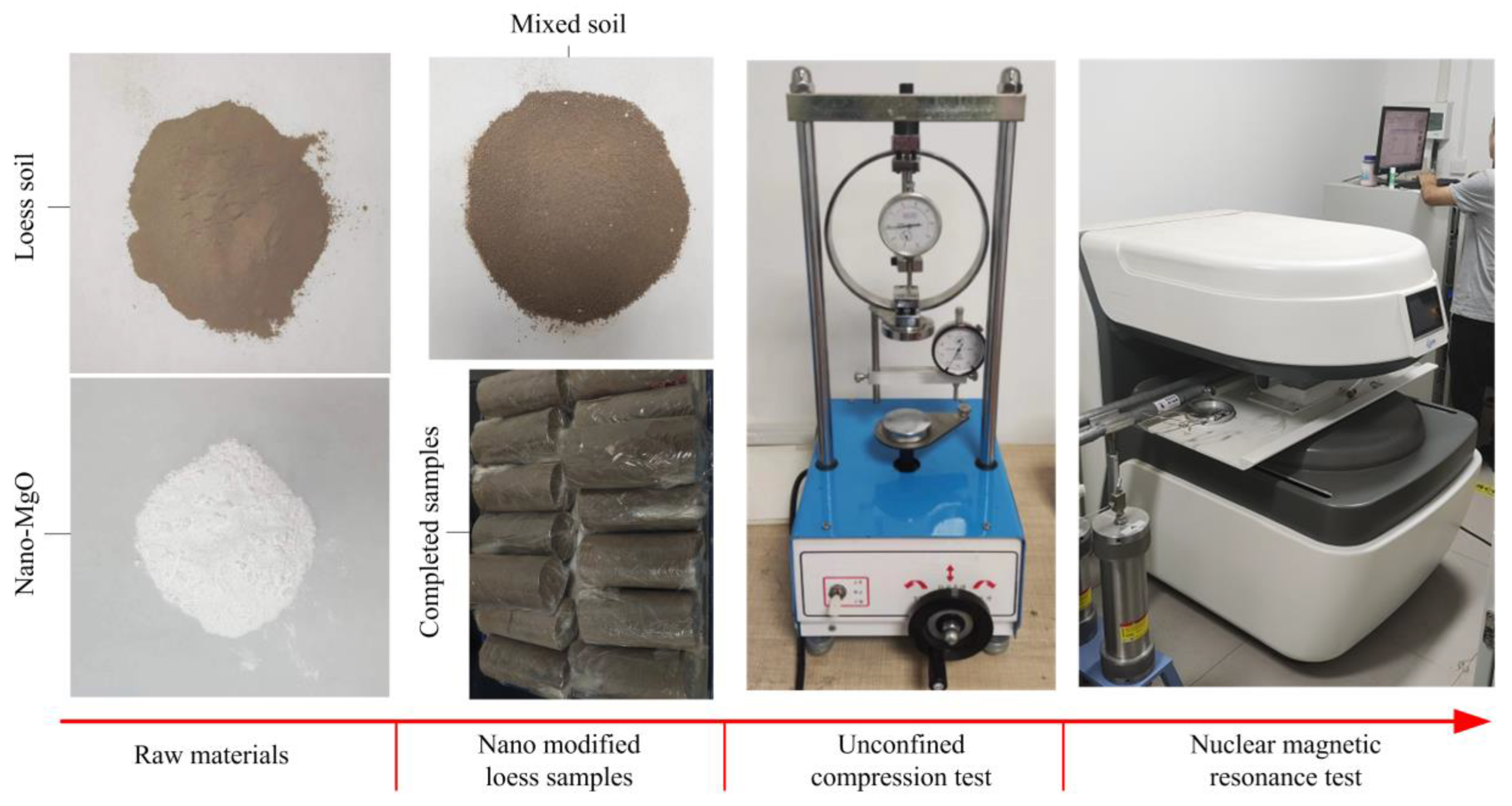
Figure 1. Raw materials and laboratory testing apparatus.
Sustainability 15 04344 g001
Figure 2. Distribution of loess and loess-like sediments in China (Li et al., 2018) [42].
Sustainability 15 04344 g002
Figure 3. Consistency limits of NM-treated loess.
Sustainability 15 04344 g003
Figure 4. Results of the standard compaction test.
Sustainability 15 04344 g004
Figure 5. The influence of NM content on stress–strain curves at curing time of: (a) 1 day; (b) 7 days; (c) 14 days; (d) 28 days; (e) 42 days.
Sustainability 15 04344 g005
Figure 6. UCS of NM-treated loess with varying NM contents and curing times.
Sustainability 15 04344 g006
Figure 7. Comparison of UCS between predicted results and experimental data.
Sustainability 15 04344 g007
Figure 8. Strain at failure of NM-treated loess with various NM contents and curing times.
Sustainability 15 04344 g008
Figure 9. Relationship between strain at failure and UCS of NM-treated loess.
Sustainability 15 04344 g009
Figure 10. Relationships between strain at failure and UCS of nanomaterial-treated clays in literature (Kalhor et al., 2019; Changizi et al., 2015; Wang et al., 2021; Ahmadi et al., 2020) [22,31,37,53].
Sustainability 15 04344 g010
Figure 11. The influence of NM content and curing time on deformation modulus for NM-treated loess.
Sustainability 15 04344 g011
Figure 12. Relationship between deformation modulus and UCS for NM-treated loess.
Sustainability 15 04344 g012
Figure 13. Relationship between deformation modulus and UCS of nano-material-treated clays extracted from literature (Kalhor et al., 2019; Changizi et al., 2015; Wang et al., 2021; Ahmadi et al., 2020) [22,31,37,53].
Sustainability 15 04344 g013
Figure 14. Effect of NM content on T2 spectra of NM-treated loess.
Sustainability 15 04344 g014
Figure 15. Effects of curing time on T2 spectra of NM-treated loess.
Sustainability 15 04344 g015
Table 1. Physical indexes of the loess soil.
PropertiesIndex Value
Physical indexSpecific gravity(-)2.64
Plastic limit(%)20.5
Liquid limit(%)34.2
Plastic index(-)13.7
Grain size distribution2~0.075 mm(%)12
0.075~0.002 mm(%)71
<0.002 mm(%)17
Mineral componentsQuartz(%)42
Feldspar(%)32
Muscovite(%)17
Montmorillonite(%)5
Illite(%)4
Table 2. Chemical and physical properties of the nano-MgO used.
Chemical CompositionPhysical Properties
FormulaConcentrationPropertyValue
MgO99.9Mean particle size40 nm
CaO0.004Melting point2850 °C
Fe2O30.002Boiling point3600 °C
TiO20.003Bulk density 0.74 g/cm3
Other0.001Specific surface area40 m2/g
Table 3. Mixing and curing design.
Test ItemSymbol C NM (-)w (-) ρ d (g/cm3) T c (day)
SCT-0%, 1%, 2%, 3%, 4%---
CLT-0%, 1%, 2%, 3%, 4%---
UCTT01~T050%, 1%, 2%, 3%, 4%wopt ρ dmax 1
T06~T107
T11~T1514
T16~T2028
T21~T2542
NMRT26~T300%, 1%, 2%, 3%, 4%18.4%1.6128
T31~T352%1, 7, 14, 28, 42
Notes: C NM : NM content; w: water content; ρ d : dry density; T c : curing time; wopt: optimum water content; ρ dmax : maximum dry density.
Disclaimer/Publisher’s Note: The statements, opinions and data contained in all publications are solely those of the individual author(s) and contributor(s) and not of MDPI and/or the editor(s). MDPI and/or the editor(s) disclaim responsibility for any injury to people or property resulting from any ideas, methods, instructions or products referred to in the content.