
A Comprehensive Review on Development and Applications of Cross-Flow Wind Turbines


Abstract
:1. Introduction
1.1. Opening
1.2. Motivation and Article Structure
- What was the history and evolution of the cross-flow rotor (CFR)?
- What are the features and applications of CFWTs?
- What are the performance improvement methods and common modeling strategies?
- What features and aspects make CFWTs attractive for harvesting energy in urban environments?
- What is the necessity to find a suitable site location?
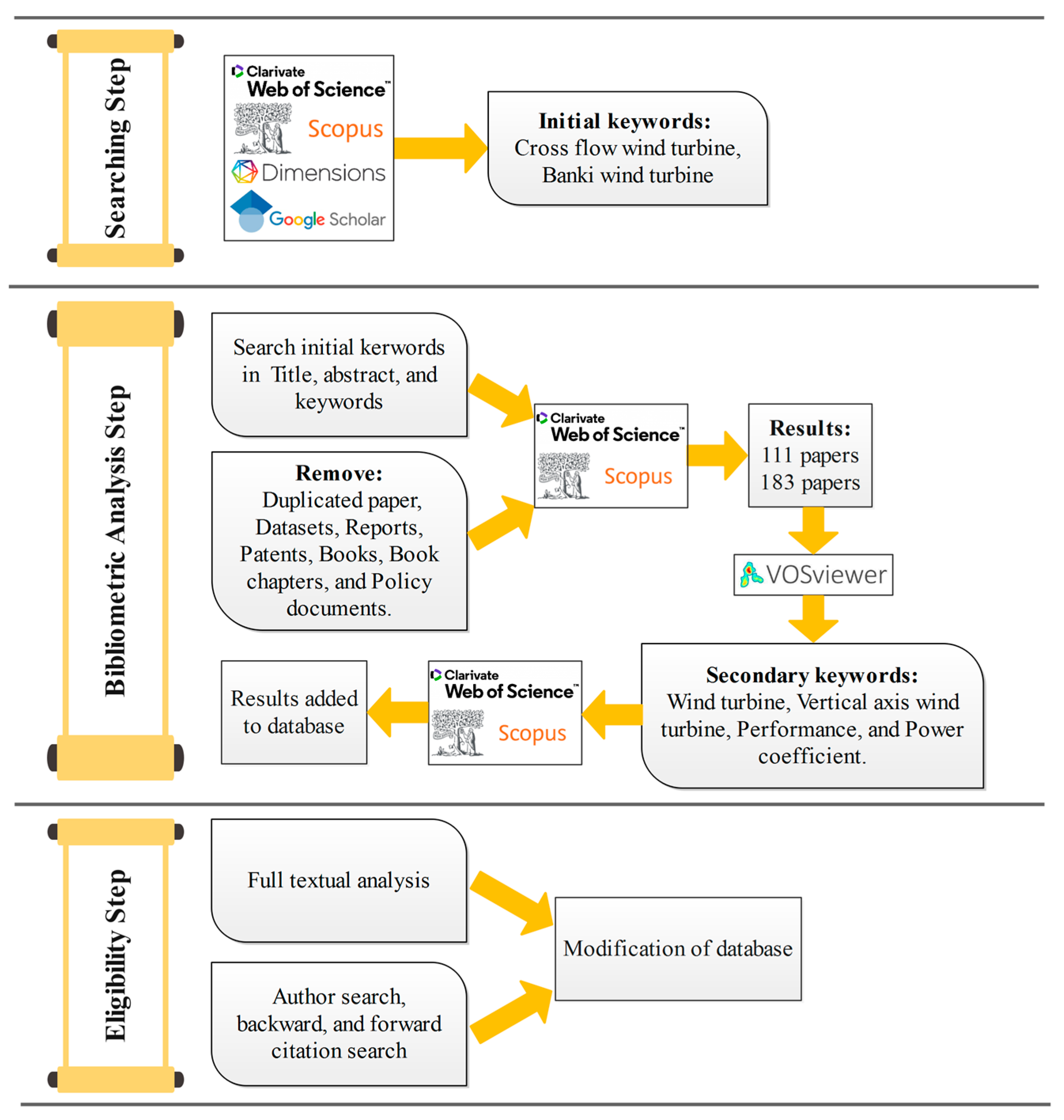
1.3. Research Methodology and Analysis
2. WTs and Principles
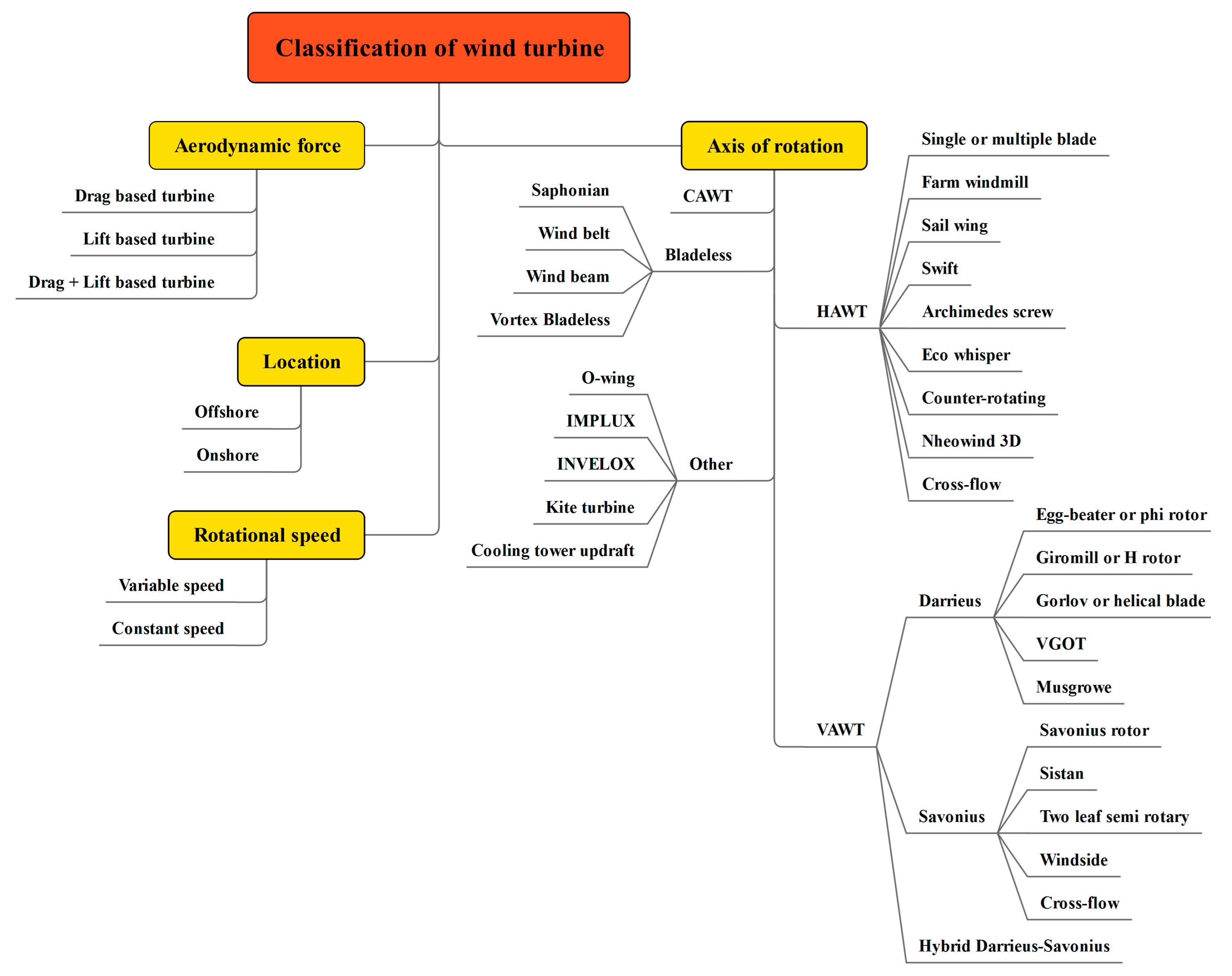
2.1. Classification of WTs
2.2. Governing Equations and Turbulence Models
3. CFWTs
3.1. History of CFR
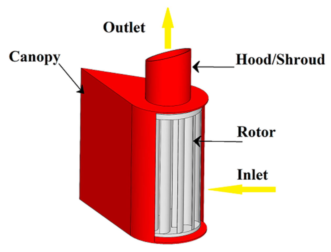
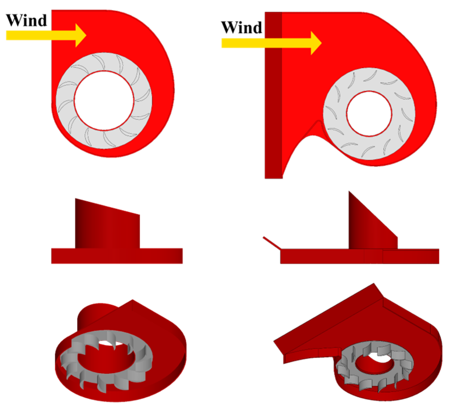
3.2. Working Principle and Applications of CFWT
3.3. Advantages and Disadvantages of CFWTs
4. Parameters Affecting the Performance of CFWT
4.1. Number of Blades
4.2. Configuration and Arrangement
4.3. Number of Stages
4.4. Blade Orientation and Shape

| Author | Year | Method | Turbine Design | Optimum Value (s) of Parameter | Remarks | Maximum CP | Maximum CT |
|---|---|---|---|---|---|---|---|
| Arifin et al. [104] | 2021 | Experimental | Number of blades = 12, 16, and 20 Wind speed = 8 and 10 m/s Aspect Ratio = 1 The effect of opposite direction rotation and the linear configuration | Number of blades = 12 Wind speed = 10 m/s | Opposite rotation and the linear configuration increase performance | 0.169 at TSR = 0.4 | 0.703 |
| Pertiwi et al. [116] | 2020 | Experimental | Linear configuration Turbine distance = 1.5D, 2D, and 2.5D Aspect Ratio = 1 Wind speed = 5, 6, and 7 m/s | Wind speed = 7 m/s linear configuration 2.5D | CP,max is 0.122 on upstream turbine and 0.082 on downstream turbine | - | - |
| Hidayat and Ismail [111] | 2019 | CFD-2D | Number of blades = 18 and 20 Angle of blade = 45°, 60°, and 75° Aspect ratio diameter = 0.68 Wind speed = 2 to 5 m/s | Number of blades = 18 Angle of blade = 45° | - | 0.45 at TSR = 0.3 | 3 at TSR = 0.1 |
| Wikantyoso et al. [114] | 2019 | CFD-2D | Blade thickness = 2.6, 10, 15, and 20 mm Number of blades = 18, 20, and 22 TSR = 0.1 to 0.5 | Blade thickness = 20 mm Number of blades = 22 | - | 0.5 at TSR = 0.2 | - |
| Kurniawati et al. [107] | 2018 | Experimental | Number of blades = 8, 16, and 20 Wind speed = 2 to 5 m/s | Number of blades = 16 | - | 0.21 at TSR = 0.59 | 0.38 at TSR = 0.4 |
| Makarim et al. [108] | 2018 | CFD-2D | Number of blades = 16, 19, and 22 Blade depth ratio = 10%, 20%, and 30% TSR = 0, 0.109, 0.218, 0.327, and 0.436 | Number of blades = 16 Blade depth ratio = 10% TSR = 0.436 | - | 0.187 | - |
| Susanto et al. [112] | 2018 | Experimental | Number of blades = 16, 20, and 24 Rotor diameter ratio = 0.58, 0.63, 0.68, and 0.73 Wind speed = 3 to 4 m/s | Number of blades = 20 Rotor diameter ratio = 0.68 | - | 0.049 at TSR = 0.34 | 0.185 at TSR = 0.19 |
| Tjahjana et al. [113] | 2018 | CFD-2D | Number of blades = 16, 20 and 24 Rotor diameter ratio = 0.58, 0.63, 0.68, and 0.73 Wind speed = 2 m/s TSR = 0.1 to 0.4 | Number of blades = 20 Rotor diameter ratio = 0.68 | - | 0.5 at TSR = 0.3 | 3.1 at TSR = 0.1 |
| Wibowo et al. [109] | 2018 | Experimental | Number of blades = 8, 12, and 16 Number of ODGV’s blade = 8, 12, and 16 The tilt angle of ODGV = 20° and 60° | Number of blades = 16 Number of ODGV’s blade = 16 The tilt angle of ODGV = 60° | - | 0.1 at TSR = 0.28 | - |
| Permadi and Siregar. [105] | 2018 | Experimental | Number of blades = 6, 8, and 12 | Number of blades = 12 | 3.76% increase in efficiency at wind speed of 5.52 m/s | - | - |
| Pujol et al. [115] | 2018 | Experimental and CFD-2D | Number of blades = 6, 11, and 22 Use CFWT as a single rotor in VAWT or as blades in HAWT | As a single rotor in HAWT with 22 blades | - | 0.41 at TSR = 0.7 | - |
| Oktavitasari et al. [118] | 2018 | Numerical (CFD-2D) | Configuration = aligned and staggered Turbine distance = 0.5D, 1D, and 1.5D Wind speed = 2 m/s | Staggered 0.5D | The appropriate distance between WTs would increase by 10% of power density | - | - |
| Santoso et al. [122] | 2018 | Experimental | Angle of blade = 30°, 45°, 60°, and 90° Blade radius = 60, 90, and 120 Wind speed = 2.8 to 4.3 m/s Rotor radius ratio (Inner to outer radius ratio) = 0.73 | Angle of blade = 45° Blade radius = 90 | - | 0.41 at TSR = 0.76 | - |
| Larin et al. [110] | 2016 | CFD-3D | Number of blades = 1 to 7 30° circumferential cut on blades = without, single and double-cut In 8 different positions on the top of the building TSR = 0.6 to 0.9 | 7-bladed turbine with double-cut blades | - | 0.24 at TSR = 0.56 | - |
| Chiarelli et al. [120,121] | 2015, 2013 | Experimental and Numerical (CFD-2D) | Rotor diameter = 0.25, 1, 4, 10, and 20 m Wind speed = 10, 15, and 20 m/s | Rotor diameter = 4 m Wind speed = 10 m/s | The bigger the rotor diameter, the higher the efficiency | 0.35 at TSR = 0.4 | - |
| Kacor et al. [123] | 2011 | Numerical | Two different angles of the blade (Option A and B) | - | Options A and B have mean torque values of 3.2 Nm and 1.8 Nm, respectively | - | - |
| Colley et al. [106] | 2009 | CFD-2D | Number of blades = 3, 6, and 12 Number of stator blades = 3, 6, and 12 TSR = 0 to 0.6 | Number of blades = 12 Number of stator blades = 12 | Peak power output decreases due to the reduction in stator/rotor blade number | - | - |
| Sato et al. [117] | 2005 | Numerical (CFD-2D) | Install multiple CFWTs in a line Angle of attack = 0°, 30°, 60°, and 90° | Angle of attack = 0° and 30° | The turbine’s performance got lowest at 90° in these calculations | - | - |
5. Augmentation Devices for CFWT
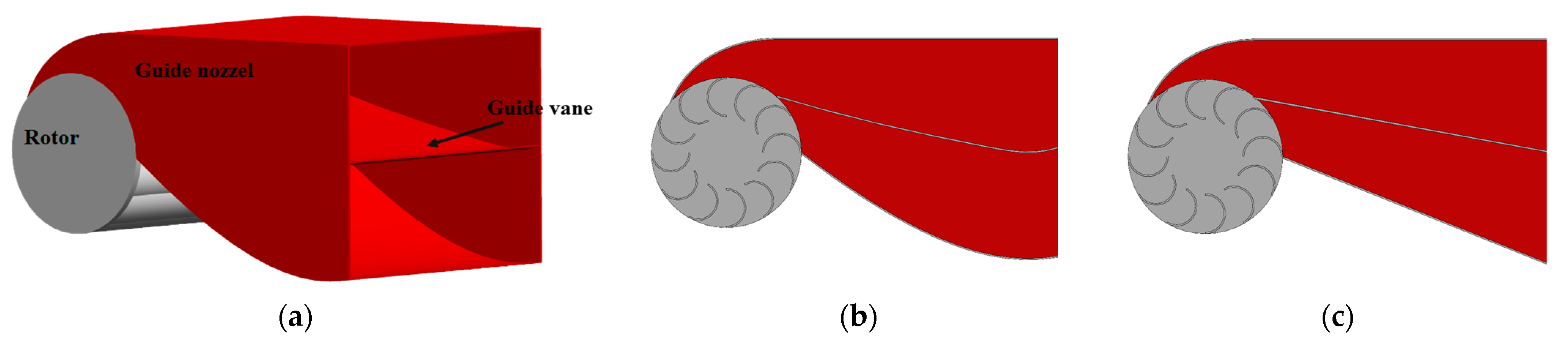
5.1. Guide Nozzle
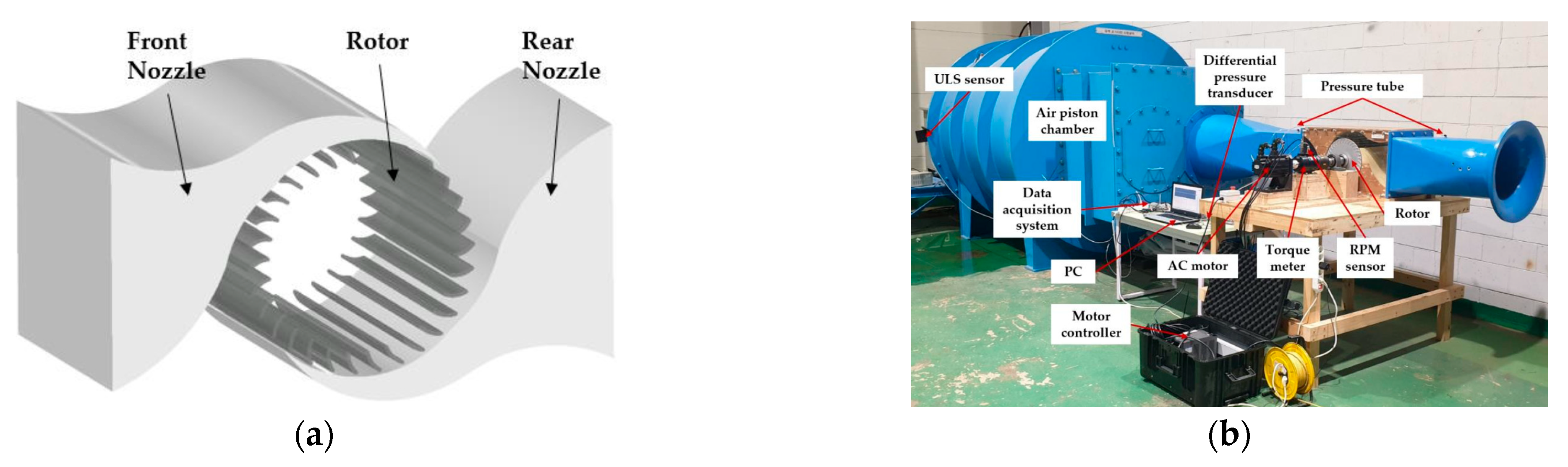
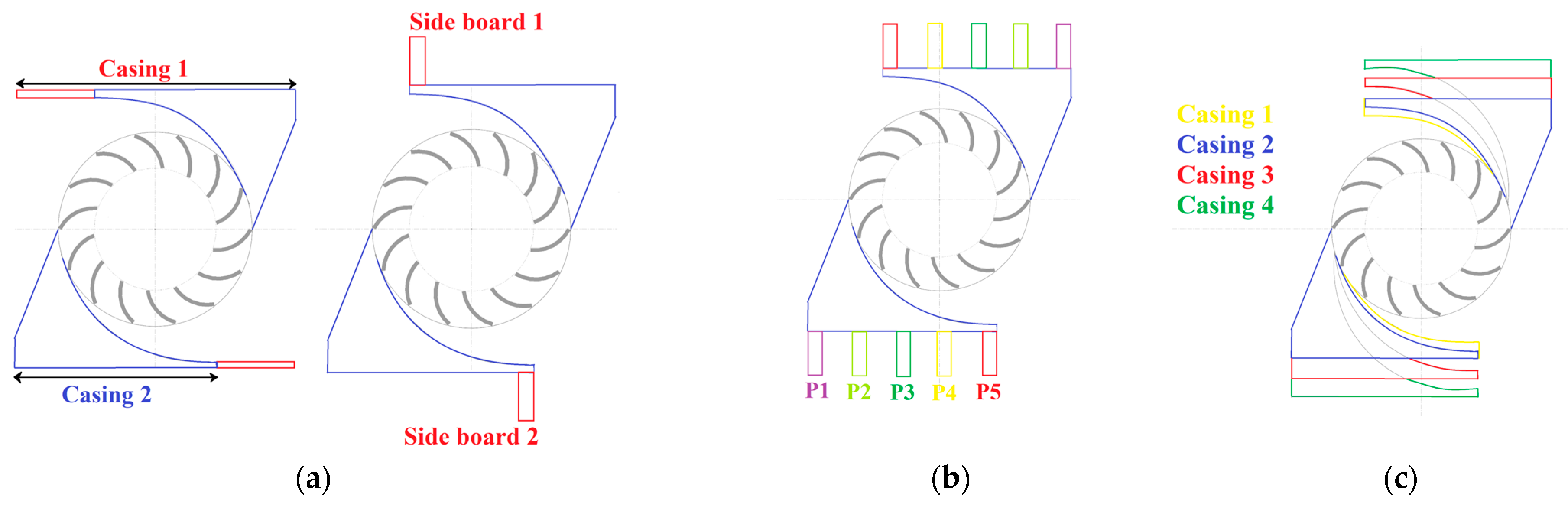
5.2. Casing
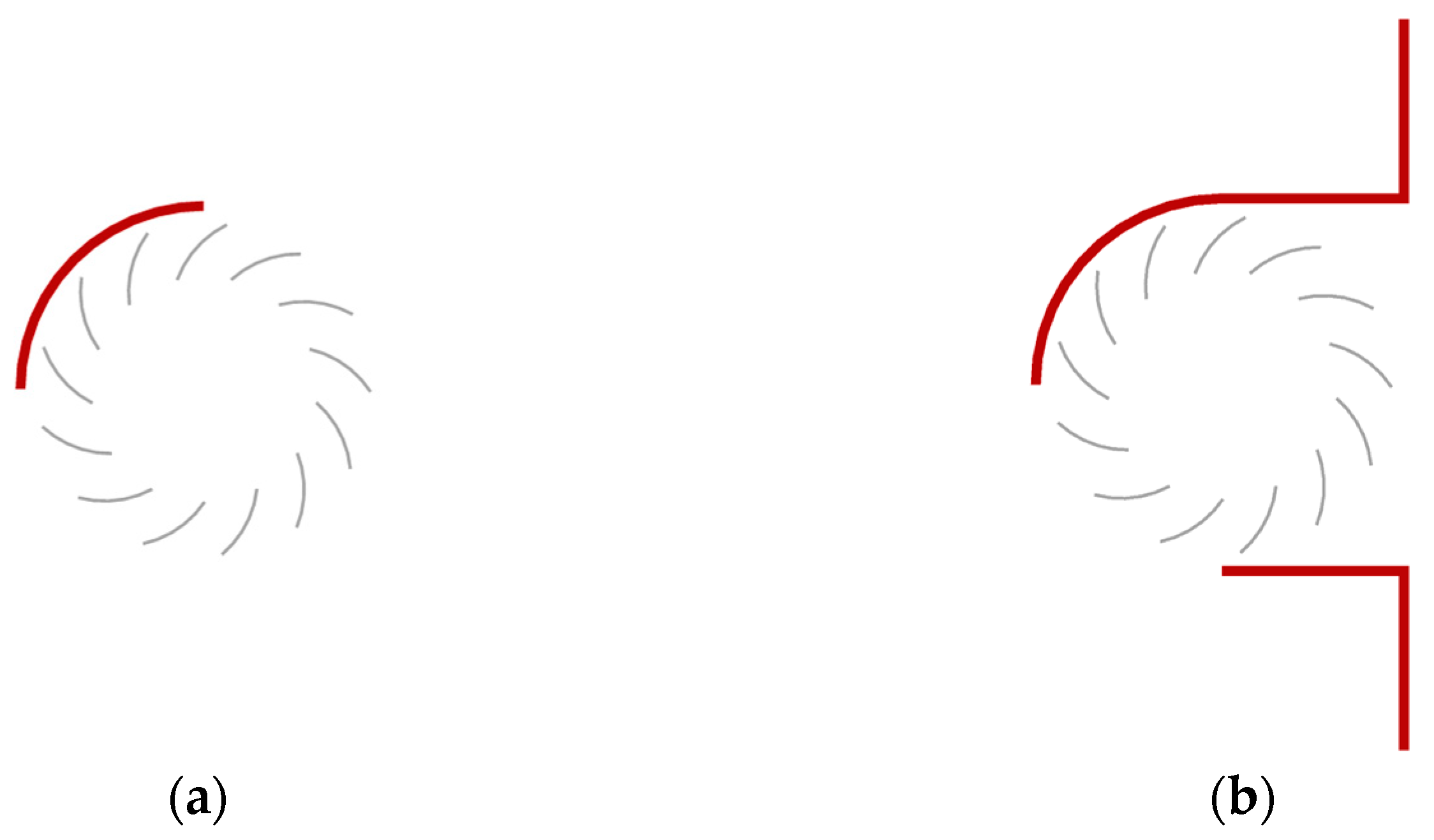
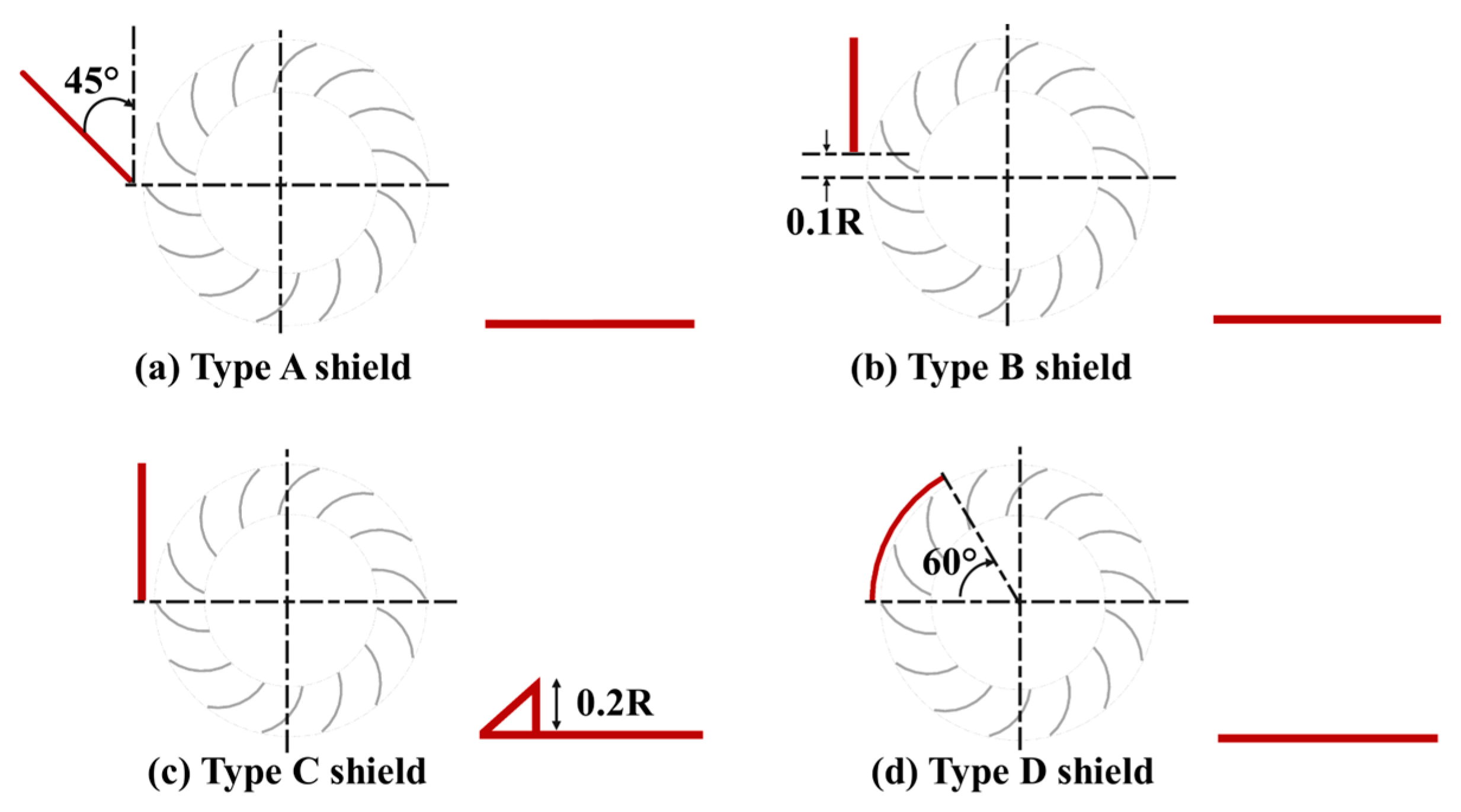
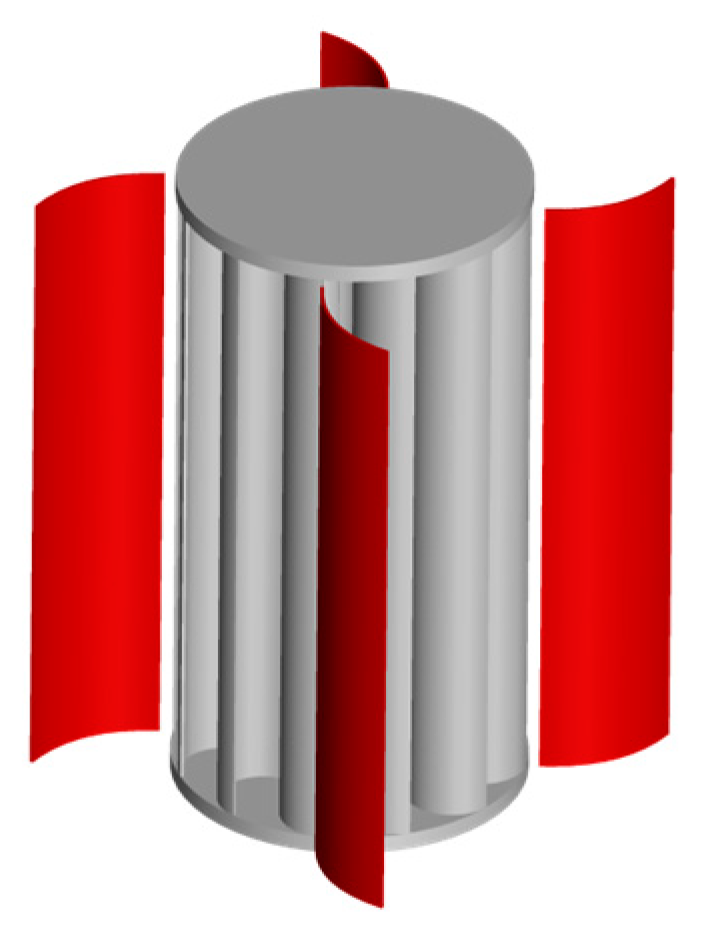
5.3. Windshield
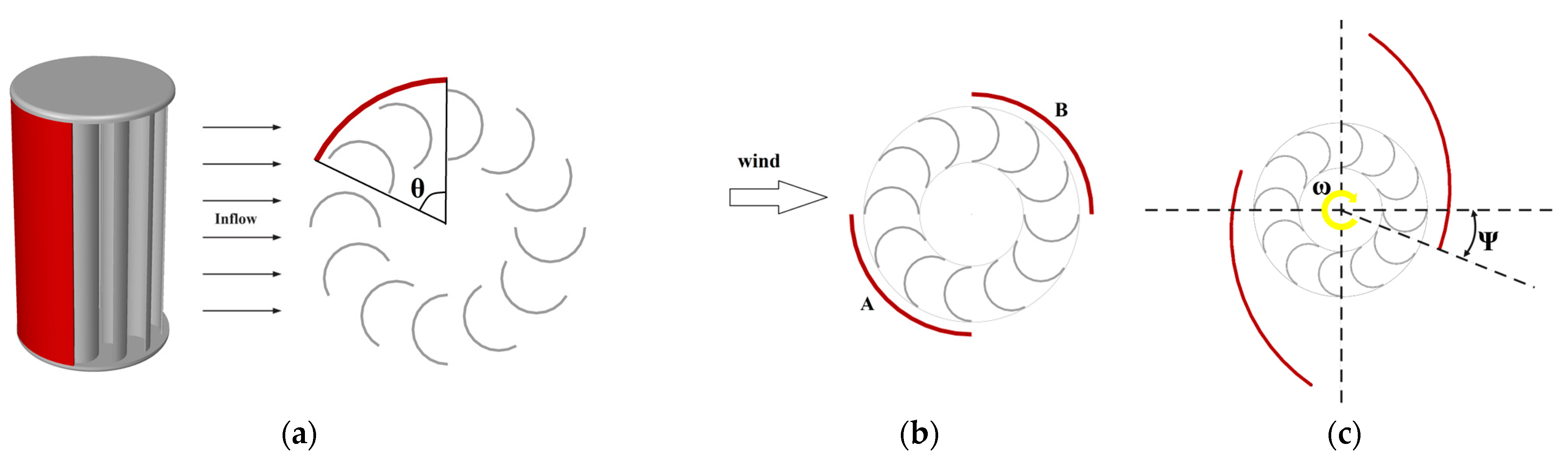
5.4. Guide Vane
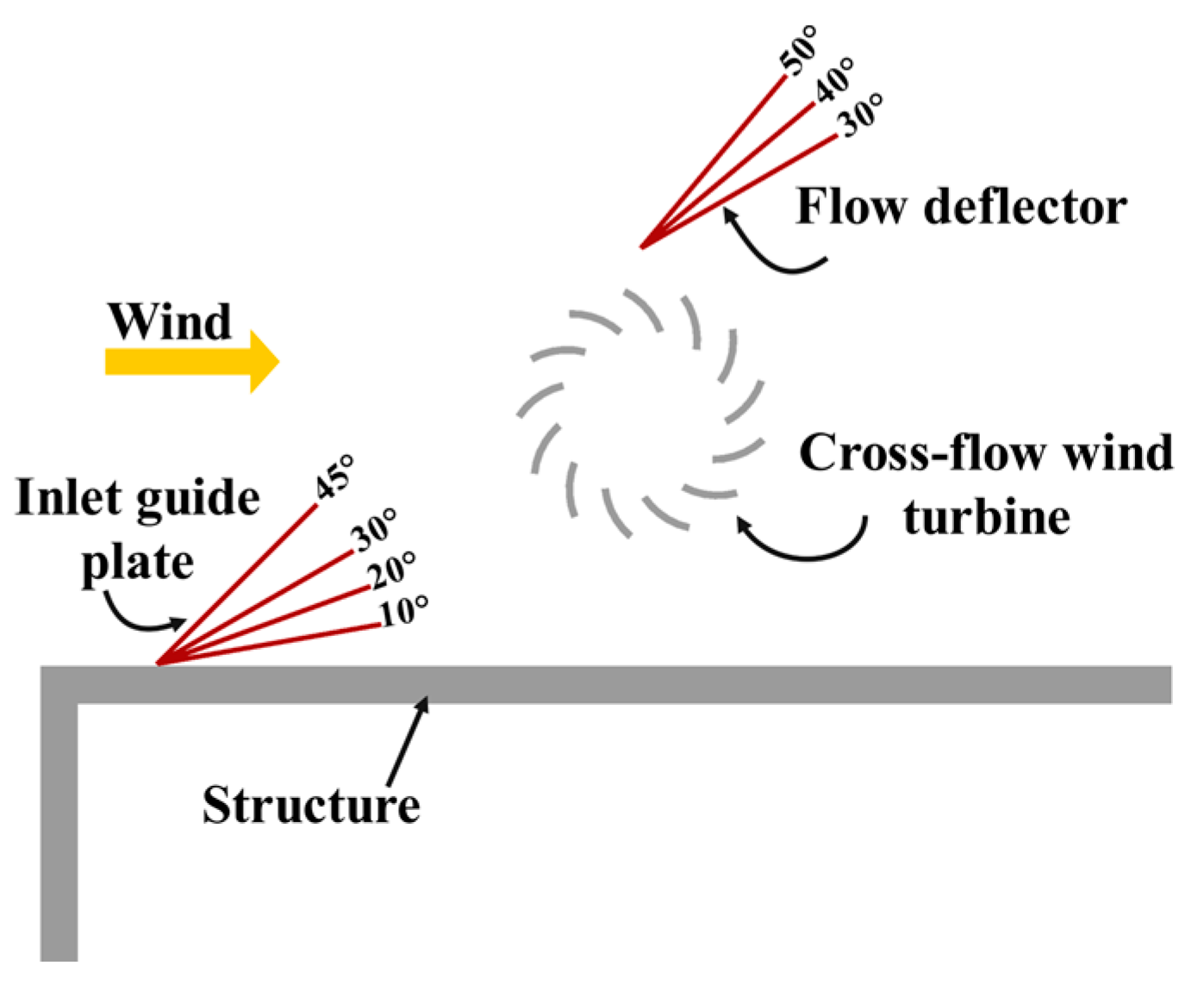
5.5. Deflector
5.6. Cowling
5.7. ODGV
5.8. Zephyr
6. Wind Energy in Buildings
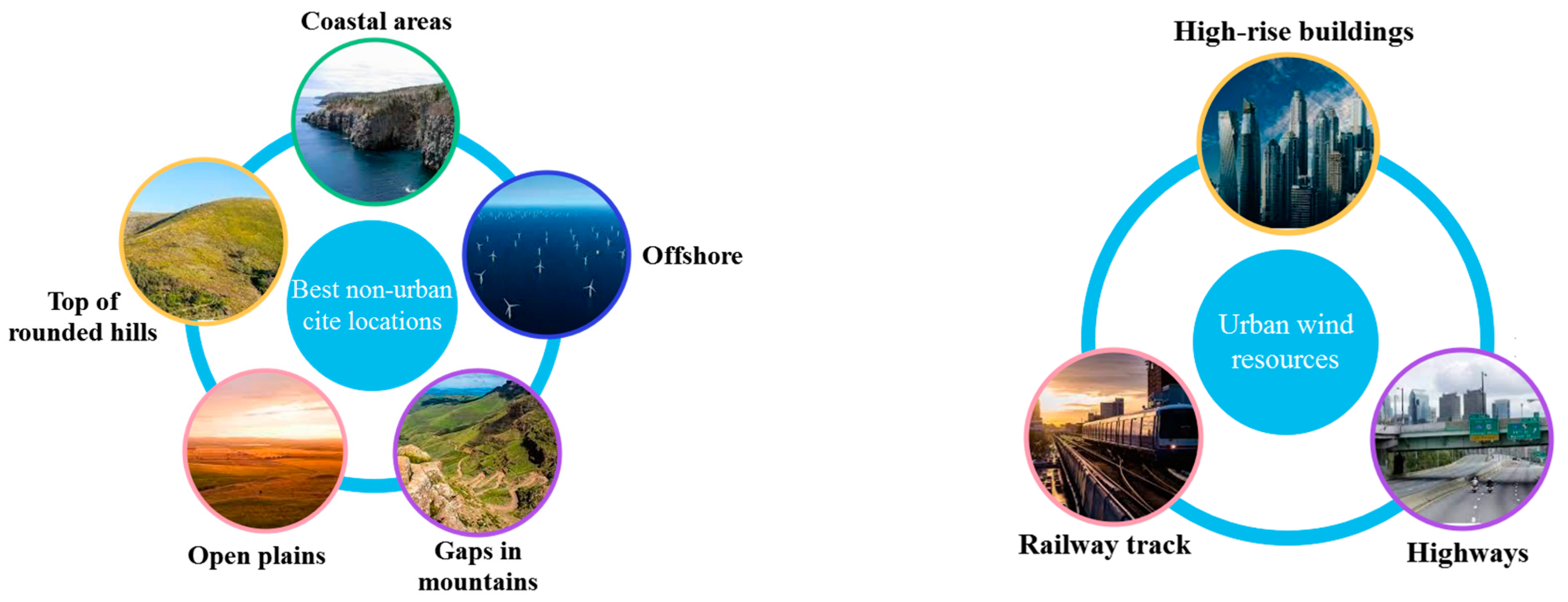
6.1. The Importance of a Suitable Site Location
6.2. Environmental, Social, and Economic Aspects
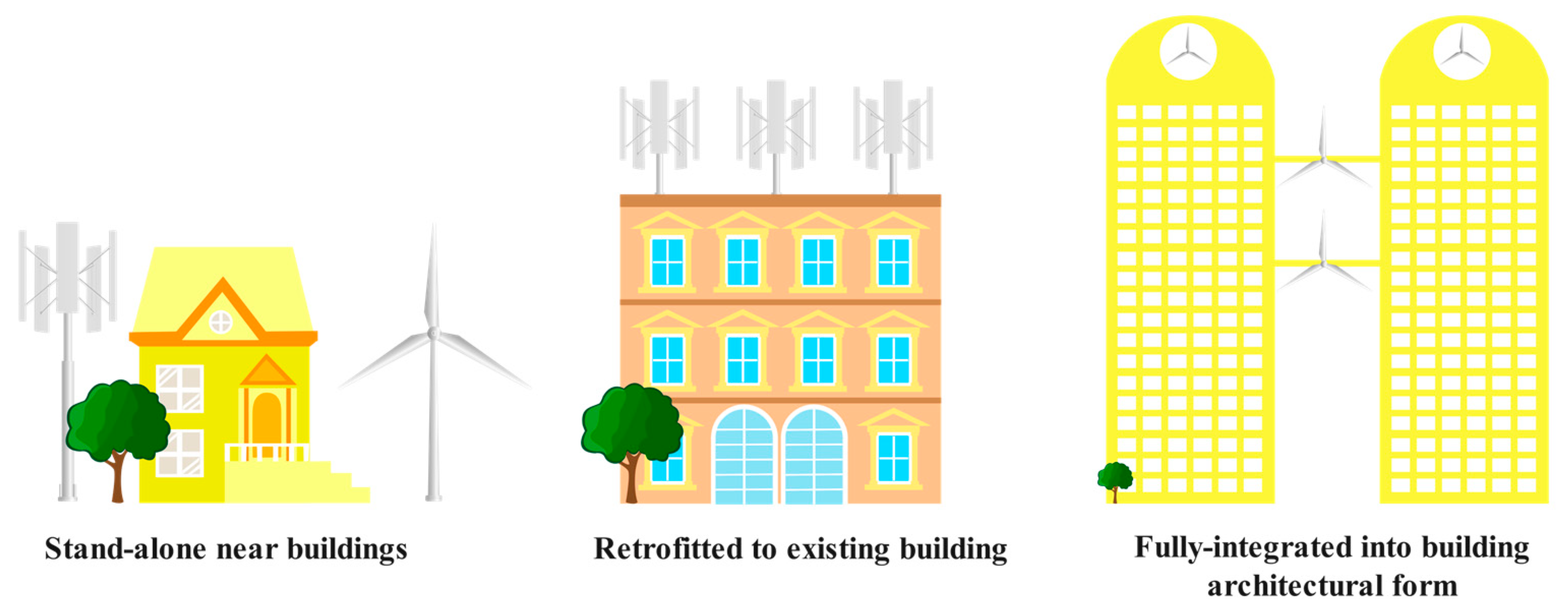
6.3. Applications in Urban Buildings
7. Challenges and Future Scopes
- Although the effect of geometrical parameters on turbine efficiency has been investigated, there is a lack of studies on aspect ratio and twisting angle of blades.
- As discussed earlier, adding an augmentation device is essential for increasing the CP. However, they increase the total weight and design complexity. The appropriate type of augmentation choice depends on the analysis of the wind rose, project costs, installation method (HAWT or VAWT), and acceptable vibration, as well as noise. Studies have yet to fill this gap.
- More numerical investigations are essential to address the fatigue behavior and acoustic, dynamic, and structural analysis of system components, which could help improve the device performance and likewise reduce the noise and cost.
- Systematic studies for the utilization of CFWTs are needed at the WF scale in rural buildings or urban high-rise buildings to see the technical feasibility of generating power from CFWTs under the influence of surrounding obstacles.
8. Conclusions
- The output of the CFWT depends on the geometrical parameters, namely angle, thickness, and circumferential length of the blade, rotor diameter ratio, and the number of blades as well as stages. If the WF scale is considered, parameters such as turbine arrangement, type of installation (VAWT or HAWT), the distance between turbines, and the direction of rotation of each one become important.
- In most studies, 12 and 16 blades were recommended, which can lead to the highest performance. Additionally, the double-stage rotor and 12° phase shift angle provide a good value of CP and reduce the negative torque.
- Selecting an appropriate TSR range can maximize CP for various configurations.
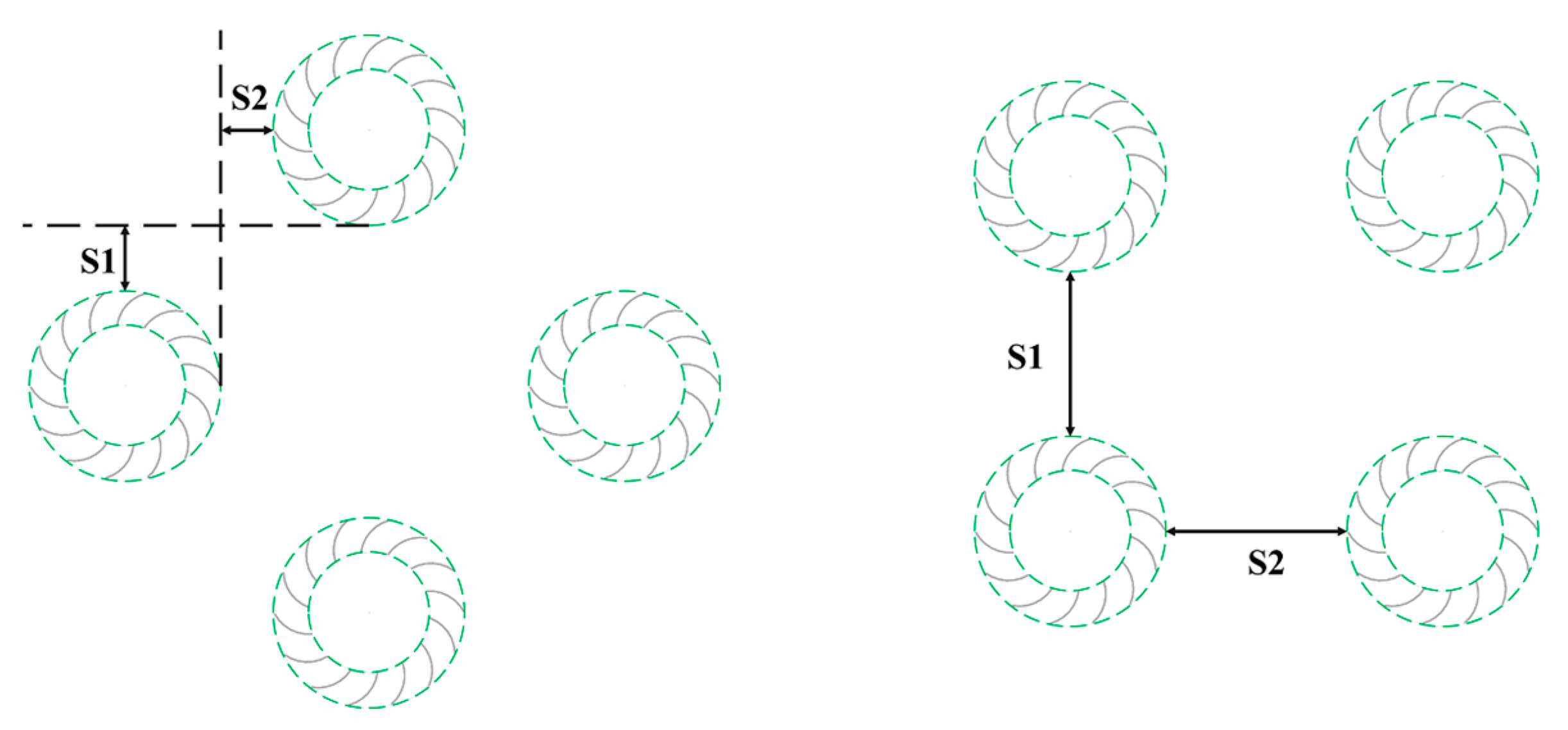
- In a linear configuration, two turbines with opposite rotation directions and at a 2.5D distance from each other reach the highest CP (D represents the outer diameter of CFWT). In a farm configuration, four turbines located in a staggered arrangement within the distance S1:S2 of 0.5D:0.5D have the highest power density. Further, using the CFWT as a single rotor in VAWT is a better arrangement than using the CFWT as 5 blades in HAWT.
- Augmentation devices include guide nozzle, casing, windshield, guide vane, deflector, cowling, ODGV, and zephyr. They reduce negative torque by preventing the wind flow from hitting the convex part of the blades or converging the wind flow, thereby increasing the CP. Based on their advantages/disadvantages and previous discussions in the literature on efficiency improvement, ODGV and guide nozzle have the best effect on CFWT performance, as they have caused an increase of 147% and 152%, respectively, in CP compared to the rotor without any augmentation device.
- Most of the research focused on the application of CFWTs has investigated this turbine in busy highways and airport runways. Nevertheless, CFWTs can be effectively integrated with buildings and harvest reasonable power output. Although the efficiency is not yet dramatically high, it could result in acceptable cost-effectiveness levels in areas with high annual wind capacity factors.
Funding
Institutional Review Board Statement
Informed Consent Statement
Data Availability Statement
Conflicts of Interest
Nomenclature
| Parameters/Variables | Abbreviations | |||
| A | m2 | Area | CAPEX | Capital expense |
| C | - | Model constant-coefficient | CAWT | Cross axis wind turbine |
| CP | - | Power coefficient | CFD | Computational fluid dynamics |
| CT | - | Torque coefficient | CFF | Cross-flow fan |
| Cμ | - | Eddy-viscosity coefficient | CFHT | Cross-flow hydro turbine |
| D | m | Diameter | CFR | Cross-flow rotor |
| N | External body forces | CFWT | Cross-flow wind turbine | |
| Gk, Gb | N/m2·s | Turbulence kinetic energy generation | HAWT | Horizontal axis wind turbine |
| H | m | Height | ODGV | Omni direction guide vane |
| I | - | Unit tensor | OWC | Oscillating Water Columns |
| k | m2/s2 | Turbulence kinetic energy | PPS | Passive-pitch shield |
| Mt | - | Turbulent Mach number | SSWT | Small-scale wind turbine |
| P | W | Power | TSR | Tip speed ratio |
| p | pa | Pressure | VAWT | Vertical axis wind turbine |
| R | m | Radius | VGOT | Variable geometry oval trajectory |
| Sε, Sk | N/m2·s | User-defined source terms | WRA | Wind resource assessment |
| T | Nm | Torque | WT | Wind turbine |
| t | s | Time | WTE | Wind tunnel experiment |
| U | m/s | linear velocity | Subscripts and Superscripts | |
| ui, vi, wi | m/s | Instantaneous velocity in tensor notation | r | Rotor |
| m/s | Relative velocity | t | Turbulent | |
| V | m/s | Wind speed | w | Wind power |
| x, y, z | m | Cartesian coordinates | ||
| YM | N/m2·s | Contribution of the fluctuating dilatation | ||
| Greek symbol | ||||
| α | deg | Angle of Attack | ||
| ε | m2/s3 | Turbulence kinetic energy dissipation rate | ||
| λ | - | Tip speed ratio | ||
| μ | N·s/m2 | Dynamic viscosity | ||
| ν | m2/s | Kinematic viscosity | ||
| ρ | kg/m3 | Density | ||
| σε, σk | - | Turbulent Prandtl number | ||
| τ | N/m2 | Stress tensor | ||
| ω | 1/s | Specific dissipation rate | ||
| ῶ | rad/s | Angular velocity | ||
References
- Gupta, A.K. Efficient Wind Energy Conversion: Evolution to Modern Design. J. Energy Resour. Technol. 2015, 137, 051201. [Google Scholar] [CrossRef]
- Lazkano, I.; Nøstbakken, L.; Pelli, M. From fossil fuels to renewables: The role of electricity storage. Eur. Econ. Rev. 2017, 99, 113–129. [Google Scholar] [CrossRef] [Green Version]
- Sahu, B.K. Wind energy developments and policies in China: A short review. Renew. Sustain. Energy Rev. 2018, 81, 1393–1405. [Google Scholar] [CrossRef]
- Behzadi, A.; Arabkoohsar, A.; Yang, Y. Optimization and dynamic techno-economic analysis of a novel PVT-based smart building energy system. Appl. Therm. Eng. 2020, 181, 115926. [Google Scholar] [CrossRef]
- International Energy Agency; International Renewable Energy Agency; United Nations; World Bank Group; World Health Organization. Tracking SDG7: The Energy Progress Report 2018; World Bank: Washington, DC, USA, 2018; Available online: https://openknowledge.worldbank.org/handle/10986/29812 (accessed on 3 July 2022).
- UNDP and WHO. The Energy Access Situation in Developing Countries: A Review Focusing on the Least Developed Countries and Sub-Saharan Africa; UNDP: New York, NY, USA, 2009. [Google Scholar]
- World Bank. Household Cookstoves, Environment, Health, and Climate Change; World Bank: Washington, DC, USA, 2011. [Google Scholar]
- World Health Organization (WHO). Burden of Disease from Household Air Pollution for 2016 Description of Method; World Health Organization: Geneva, Switzerland, 2018. [Google Scholar]
- Bazilian, M.; Nussbaumer, P.; Cabraal, A.; Centurelli, R.; Detchon, R.; Gielen, D.; Howells, M.; Mcmahon, H.; Modi, V.; O’gallachoir, B.; et al. Measuring Energy Access: Supporting a Global Target; Columbia University: New York, NY, USA, 2010; Available online: https://pure.iiasa.ac.at/id/eprint/9372/ (accessed on 3 July 2022).
- Guo, S.; Liu, Q.; Sun, J.; Jin, H. A review on the utilization of hybrid renewable energy. Renew. Sustain. Energy Rev. 2018, 91, 1121–1147. [Google Scholar] [CrossRef]
- Nabat, M.H.; Zeynalian, M.; Razmi, A.R.; Arabkoohsar, A.; Soltani, M. Energy, exergy, and economic analyses of an innovative energy storage system; liquid air energy storage (LAES) combined with high-temperature thermal energy storage (HTES). Energy Convers. Manag. 2020, 226, 113486. [Google Scholar] [CrossRef]
- Behzadi, A.; Arabkoohsar, A. Comparative performance assessment of a novel cogeneration solar-driven building energy system integrating with various district heating designs. Energy Convers. Manag. 2020, 220, 113101. [Google Scholar] [CrossRef]
- Arabkoohsar, A. Combined steam based high-temperature heat and power storage with an Organic Rankine Cycle, an efficient mechanical electricity storage technology. J. Clean. Prod. 2020, 247, 119098. [Google Scholar] [CrossRef]
- Sundqvist, T.; Söderholm, P. Valuing the Environmental Impacts of Electricity Generation: A Critical Survey. J. Energy Lit. 2002, 8, 3–41. [Google Scholar]
- Heier, S. Grid Integration of Wind Energy: Onshore and Offshore Conversion Systems; John Wiley & Sons: Hoboken, NJ, USA, 2014. [Google Scholar]
- Ackermann, T.; Söder, L. Wind energy technology and current status: A review. Renew. Sustain. Energy Rev. 2000, 4, 315–374. [Google Scholar] [CrossRef]
- Ackermann, T. Wind Power in Power Systems; John Wiley & Sons: Hoboken, NJ, USA, 2012. [Google Scholar]
- Bull, S.R. Renewable energy today and tomorrow. Proc. IEEE 2001, 89, 1216–1226. [Google Scholar] [CrossRef]
- REN21. Renewables 2022 Global Status Report; REN21: Paris, France, 2022. [Google Scholar]
- Roy, S.; Saha, U.K. Review on the numerical investigations into the design and development of Savonius wind rotors. Renew. Sustain. Energy Rev. 2013, 24, 73–83. [Google Scholar] [CrossRef]
- Kang, C.; Liu, H.; Yang, X. Review of fluid dynamics aspects of Savonius-rotor-based vertical-axis wind rotors. Renew. Sustain. Energy Rev. 2014, 33, 499–508. [Google Scholar] [CrossRef]
- Tang, Z.P.; Yao, Y.X.; Zhou, L.; Yu, B.W. A review on the new structure of Savonius wind turbines. Adv. Mater. Res. 2013, 608, 467–478. [Google Scholar] [CrossRef]
- Fanel Dorel, S.; Adrian Mihai, G.; Nicusor, D. Review of Specific Performance Parameters of Vertical Wind Turbine Rotors Based on the SAVONIUS Type. Energies 2021, 14, 1962. [Google Scholar] [CrossRef]
- Kumar, R.; Raahemifar, K.; Fung, A.S. A critical review of vertical axis wind turbines for urban applications. Renew. Sustain. Energy Rev. 2018, 89, 281–291. [Google Scholar] [CrossRef]
- Mertens, S. Wind Energy in the Built Environment: Concentrator Effects of Buildings; Multi-Science: Essex, UK, 2006. [Google Scholar]
- Simão Ferreira, C.; Van Kuik, G.; Van Bussel, G.; Scarano, F. Visualization by PIV of dynamic stall on a vertical axis wind turbine. Exp. Fluids 2009, 46, 97–108. [Google Scholar] [CrossRef] [Green Version]
- Simic, Z.; Havelka, J.G.; Bozicevic Vrhovcak, M. Small wind turbines—A unique segment of the wind power market. Renew. Energy 2013, 50, 1027–1036. [Google Scholar] [CrossRef]
- Khorsand, I.; Kormos, C.; MacDonald, E.G.; Crawford, C. Wind energy in the city: An interurban comparison of social acceptance of wind energy projects. Energy Res. Soc. Sci. 2015, 8, 66–77. [Google Scholar] [CrossRef]
- Alom, N.; Saha, U.K. Evolution and progress in the development of savonius wind turbine rotor blade profiles and shapes. J. Sol. Energy Eng. 2019, 141, 30801. [Google Scholar] [CrossRef]
- Kirke, B.K. Evaluation of Self-Starting Vertical Axis Wind Turbines for Stand-Alone Applications; Griffith University: Brisbane, Australia, 1998. [Google Scholar]
- D’Ambrosio, M.; Medaglia, M. Vertical Axis Wind Turbines: History, Technology and Applications. 2010. Available online: http://windharvest.com/wp-content/uploads/2018/02/Vertical-Axis-Wind-Turbines-History-Technology-and-Applications.pdf (accessed on 29 November 2022).
- Atash, F. The deterioration of urban environments in developing countries: Mitigating the air pollution crisis in Tehran, Iran. Cities 2007, 24, 399–409. [Google Scholar] [CrossRef]
- Tjiu, W.; Marnoto, T.; Mat, S.; Ruslan, M.H.; Sopian, K. Darrieus vertical axis wind turbine for power generation I: Assessment of Darrieus VAWT configurations. Renew. Energy 2015, 75, 50–67. [Google Scholar] [CrossRef]
- Tasneem, Z.; Al Noman, A.; Das, S.K.; Saha, D.K.; Islam, M.R.; Ali, M.F.; R Badal, M.F.; Ahamed, M.H.; Moyeen, S.I.; Alam, F. An analytical review on the evaluation of wind resource and wind turbine for urban application: Prospect and challenges. Dev. Built Environ. 2020, 4, 100033. [Google Scholar] [CrossRef]
- Rajpar, A.H.; Ali, I.; Eladwi, A.E.; Bashir, M.B.A. Recent Development in the Design of Wind Deflectors for Vertical Axis Wind Turbine: A Review. Energies 2021, 14, 5140. [Google Scholar] [CrossRef]
- Dewan, A.; Gautam, A.; Goyal, R. Savonius wind turbines: A review of recent advances in design and performance enhancements. Mater. Today Proc. 2021, 47, 2976–2983. [Google Scholar] [CrossRef]
- Das Karmakar, S.; Chattopadhyay, H. A review of augmentation methods to enhance the performance of vertical axis wind turbine. Sustain. Energy Technol. Assess. 2022, 53, 102469. [Google Scholar] [CrossRef]
- Cuevas-Carvajal, N.; Cortes-Ramirez, J.S.; Norato, J.A.; Hernandez, C.; Montoya-Vallejo, M.F. Effect of geometrical parameters on the performance of conventional Savonius VAWT: A review. Renew. Sustain. Energy Rev. 2022, 161, 112314. [Google Scholar] [CrossRef]
- Cuesta, A.; Gomez-Gil, F.; Fraile, J.; Rodríguez, J.; Calvo, J.; Vara, J. Feasibility of a Simple Small Wind Turbine with Variable-Speed Regulation Made of Commercial Components. Energies 2013, 6, 3373–3391. [Google Scholar] [CrossRef] [Green Version]
- Chong, W.-T.; Muzammil, W.K.; Wong, K.-H.; Wang, C.-T.; Gwani, M.; Chu, Y.-J.; Poh, S.-C. Cross axis wind turbine: Pushing the limit of wind turbine technology with complementary design. Appl. Energy 2017, 207, 78–95. [Google Scholar] [CrossRef]
- Chong, W.-T.; Wong, K.-H.; Wang, C.-T.; Gwani, M.; Chu, Y.-J.; Chia, W.-C.; Poh, S.-C. Cross-Axis-Wind-Turbine: A Complementary Design to Push the Limit of Wind Turbine Technology. Energy Procedia 2017, 105, 973–979. [Google Scholar] [CrossRef]
- Bardakjian, A.T.; Mandadakis, P.P.; Tingle, A. Efficiency comparison of horizontal axis wind turbines and bladeless turbines. PAM Rev. Energy Sci. Technol. 2017, 4, 59–75. [Google Scholar] [CrossRef] [Green Version]
- Das, A.; Talapatra, P.K. Modelling and analysis of a mini vertical axis wind turbine. Int. J. Emerg. Technol. Adv. Eng. 2016, 6, 184–194. [Google Scholar]
- Vidal, C.D. Diseño de un aerogenerador Savonius para uso doméstico, UNIVERSITAT POLITÈCNICA DE VALÈNCIA. 2019. Available online: https://riunet.upv.es/handle/10251/131197 (accessed on 9 February 2023).
- Marie, D.G.J. Turbine Having Its Rotating Shaft Transverse to the Flow of the Current. Google Patents US1835018A, 8 December 1931. Available online: https://patents.google.com/patent/US1835018A/en (accessed on 9 February 2023).
- Wilson, R.E.; Lissaman, P.B.S. Applied Aerodynamics of Wind Power Machines; Oregon State University: Corvallis, OR, USA, 1974. [Google Scholar]
- Savonius, S.J. The S-rotor and its applications. Mech. Eng. 1931, 53, 333–338. [Google Scholar]
- Tummala, A.; Velamati, R.K.; Sinha, D.K.; Indraja, V.; Krishna, V.H. A review on small scale wind turbines. Renew. Sustain. Energy Rev. 2016, 56, 1351–1371. [Google Scholar] [CrossRef]
- Arab Energy. Available online: https://www.arabenergy.de/windelectricsystems.html (accessed on 10 August 2021).
- nr21 DESIGN STUDIO. Available online: https://nr21.com/lws/ (accessed on 20 October 2021).
- LWS Micro Turbine til Tag Eller Hjørne Montage 50 | Campen Auktioner A/S. Available online: https://campenauktioner.hibid.com/lot/36479802/lws-micro-turbine-til-tag-eller-hj-rne-montage--50/?q=&ref=catalog (accessed on 1 August 2021).
- Gosman, A. Developments in CFD for industrial and environmental applications in wind engineering. J. Wind Eng. Ind. Aerodyn. 1999, 81, 21–39. [Google Scholar] [CrossRef]
- Launder, B.E.; Spalding, D.B. The Numerical Computation of Turbulent Flows. Comput. Methods Applied Mechanical Engineering 1974, 3, 269–289. [Google Scholar] [CrossRef]
- Shih, T.-H.; Liou, W.W.; Shabbir, A.; Yang, Z.; Zhu, J. A new k-ϵ eddy viscosity model for high reynolds number turbulent flows. Comput. Fluids 1995, 24, 227–238. [Google Scholar] [CrossRef]
- Wilcox, D.C. Reassessment of the scale-determining equation for advanced turbulence models. AIAA J. 1988, 26, 1299–1310. [Google Scholar] [CrossRef]
- Menter, F. Zonal Two Equation k-w Turbulence Models For Aerodynamic Flows. In Proceedings of the 23rd Fluid Dynamics, Plasmadynamics, and Lasers Conference, Orlando, FL, USA, 6–9 July 1993. [Google Scholar] [CrossRef]
- Menter, F.R. Two-equation eddy-viscosity turbulence models for engineering applications. AIAA J. 1994, 32, 1598–1605. [Google Scholar] [CrossRef] [Green Version]
- Hansen, M. Aerodynamics of Wind Turbines; Routledge: London, UK, 2015. [Google Scholar]
- Betz, A. Das Maximum der theoretisch möglichen Ausnutzung des Windes durch Windmotoren. Z. Gesamte Turbinenwesten 1920, 26, 307–309. [Google Scholar]
- Adaramola, M. Wind Turbine Technology: Principles and Design; CRC Press: Boca Raton, FL, USA, 2014. [Google Scholar]
- Tong, W. Wind Power Generation and Wind Turbine Design; WIT Press: Boston, MA, USA, 2010. [Google Scholar]
- Thomson, J.R. Chapter 4. The Human–Machine Interface. High Integr. Syst. Saf. Manag. Hazard. Ind. 2015, 55–73. [Google Scholar] [CrossRef]
- Dalin, H. Improvements in Rotary Fans. GB291007A, 1928. Available online: https://worldwide.espacenet.com/patent/search/family/020307248/publication/GB291007A?q=GB291007A (accessed on 9 February 2023).
- Anderson, E.L. Unit Heater and Ventilator. US1823579A, 1931. Available online: https://worldwide.espacenet.com/patent/search/family/023831987/publication/US1823579A?q=US1823579A (accessed on 9 February 2023).
- Anderson, E.L. Line Flow Fan. US1838169A, 1933. Available online: https://worldwide.espacenet.com/patent/search/family/023426100/publication/US1838169A?q=US1838169A (accessed on 9 February 2023).
- Buck, C.M. Pulverized Fuel Feeder. US1893857A, 1933. Available online: https://worldwide.espacenet.com/patent/search/family/024000990/publication/US1893857A?q=US1893857A (accessed on 9 February 2023).
- Buck, C.M. Blower. US2033273A, 1936. Available online: https://worldwide.espacenet.com/patent/search/family/027054408/publication/US2033273A?q=US2033273A (accessed on 9 February 2023).
- Banki, D. Water Turbine. US1436933A, 1922. Available online: https://worldwide.espacenet.com/patent/search/family/023154518/publication/US1436933A?q=US1436933A (accessed on 9 February 2023).
- Ossberger, F. Free jet Turbine. DE361593 (C), 1922. Available online: https://worldwide.espacenet.com/patent/search/family/007353041/publication/DE361593C?q=DE361593 (accessed on 9 February 2023).
- Ossberger, F. Flow Turbine. DE615445 (C), 1935. Available online: https://worldwide.espacenet.com/patent/search/family/007355252/publication/DE615445C?q=DE615445 (accessed on 9 February 2023).
- Mandiş, I.C.; Robescu, D.N.; Bărglăzan, M.; Capitalization Of Wind Potential Using A Modified Banki Turbine. May 2008. Available online: https://www.scientificbulletin.upb.ro/rev_docs_arhiva/full86536.pdf (accessed on 9 February 2023).
- Moga, I.C.; Robescu, D.L.; Robescu, D.N.; Bărglăzan, M. Adjustment of Banki hydraulic turbine in order to obtain electrical energy from wind potential,(ed) UPB Scientific Bulletin. Ser. C 2007, 69, 4. [Google Scholar]
- Klemm, T.; Gabi, M.; Heraud, J.-N. Application of a cross flow fan as wind turbine. J. Comput. Appl. Mech. 2007, 8, 123–133. [Google Scholar]
- Kawamura, T.; Takami, H.; Kuwahara, K. Computation of high Reynolds number flow around a circular cylinder with surface roughness. Fluid Dyn. Res. 1986, 1, 145–162. [Google Scholar] [CrossRef]
- Tan, S. An Experimental Study of Cross Flow Wind Turbine. In Proceedings of the 75th JSME Spring Annual Meeting (in Japanese): Volume 3, Tokyo Institute of Technology, Tokyo, Japan, 31 March–3 April 1998; pp. 291–292. [Google Scholar]
- Ushiyama, I.; Isshiki, N.; Chai, G.-Z. Design Configuration and Performance Evaluation of Cross-Flow Wind Rotors. J. JSES 1994, 20, 36–41. [Google Scholar]
- Shimizu, Y.; Takada, M.; Sakata, J. Development of a high-performance cross-flow wind turbine (On the effects of ring-diffusers and multiple-guide vanes on the power augmentation for a cross-flow wind turbine). Trans. Japan Soc. Mech. Eng. Part B 1998, 64, 2958–2963. [Google Scholar] [CrossRef] [Green Version]
- Tanino, T. Influence of Number of Blade and Blade Setting Angle on the Performance of a Cross-flow Wind Turbine. Trans. Japan Soc. Mech. Eng. Ser. B 2007, 73, 225–230. [Google Scholar] [CrossRef] [Green Version]
- Motohashi, H. Performance Improvement of a Cross Flow Wind Turbine by Guide Vanes Considered Primary Wind Direction. Trans. Japan Soc. Mech. Eng. Ser. B 2004, 70, 105–110. [Google Scholar] [CrossRef] [Green Version]
- Fukutomi, J. The characteristics and Internal Flow of The Cross-Flow Hydro-Turbine for micro turbine. Turbomach 2000, 28, 3. [Google Scholar]
- Layeghmand, K.; Ghiasi Tabari, N.; Zarkesh, M. Improving efficiency of Savonius wind turbine by means of an airfoil-shaped deflector. J. Braz. Soc. Mech. Sci. Eng. 2020, 42, 528. [Google Scholar] [CrossRef]
- Jang, H.; Paek, I.; Kim, S.; Jeong, D. Performance Prediction and Validation of a Small-Capacity Twisted Savonius Wind Turbine. Energies 2019, 12, 1721. [Google Scholar] [CrossRef] [Green Version]
- Mo, Q.; Wen, J.; Liu, X.; Wang, J. The Brake System and Method of the Small Vertical Axis Wind Turbine. In Proceedings of the 2016 5th International Conference on Civil, Architectural and Hydraulic Engineering (ICCAHE 2016); Atlantis Press: Paris, France, 2016; pp. 145–151. [Google Scholar]
- Dai, S.F.; Liu, H.J.; Chu, Y.J.; Lam, H.F. Impact of corner modification on wind characteristics and wind energy potential over flat roofs of tall buildings. Energy 2022, 241, 122920. [Google Scholar] [CrossRef]
- Peng, H.Y.; Abohela, I.; Hamza, N.; Dudek, S. Effect of roof shape on energy yield and positioning of roof mounted wind turbines. In Proceedings of the Building Simulation 2011: 12th Conference of International Building Performance Simulation Association, Sydney, Australia, 14–16 November; 16 November 2011; pp. 1203–1210. [Google Scholar]
- Ismaeel, T.; Aljabair, S.; Abdulrazzaq, O.; Abood, Y. Energy recovery of moving vehicles’ wakes in highways by vertical axis wind turbines. FME Trans. 2020, 48, 557–565. [Google Scholar] [CrossRef]
- Ali, N.M.; Ammari, H. Design of a hybrid wind-solar street lighting system to power LED lights on highway poles. AIMS Energy 2022, 10, 177–190. [Google Scholar] [CrossRef]
- Hu, W.; Jiaqiang, E.; Tan, Y.; Zhang, F.; Liao, G. Modified wind energy collection devices for harvesting convective wind energy from cars and trucks moving in the highway. Energy 2022, 247, 123454. [Google Scholar] [CrossRef]
- Tian, W.; Song, B.; Mao, Z. Numerical investigation of wind turbines and turbine arrays on highways. Renew. Energy 2020, 147, 384–398. [Google Scholar] [CrossRef]
- Tian, W.; Mao, Z.; Li, Y. Numerical Simulations of a VAWT in the Wake of a Moving Car. Energies 2017, 10, 478. [Google Scholar] [CrossRef] [Green Version]
- Matias, I.J.T.; Danao, L.A.M.; Abuan, B.E. Numerical Investigation on the Effects of Varying the Arc length of a Windshield on the Performance of a Highway Installed Banki Wind Turbine. Fluids 2021, 6, 285. [Google Scholar] [CrossRef]
- Tian, W.; Mao, Z.; An, X.; Zhang, B.; Wen, H. Numerical study of energy recovery from the wakes of moving vehicles on highways by using a vertical axis wind turbine. Energy 2017, 141, 715–728. [Google Scholar] [CrossRef]
- Qusai, S.; Esraa, S.; Aseel, R. Polycarbonate Bladed Highway Wind Turbine: A Case Study. In 2021 12th International Renewable Engineering Conference (IREC); IEEE: Piscataway, NJ, USA, 2021; pp. 1–5. [Google Scholar] [CrossRef]
- Kang, H.-G.; Lee, Y.-H.; Kim, C.-J.; Kang, H.-D. Design Optimization of a Cross-Flow Air Turbine for an Oscillating Water Column Wave Energy Converter. Energies 2022, 15, 2444. [Google Scholar] [CrossRef]
- Takao, M.; Setoguchi, T. Air Turbines for Wave Energy Conversion. Int. J. Rotating Mach. 2012, 2012, 717398. [Google Scholar] [CrossRef] [Green Version]
- Kang, H.-G.; Kim, B.-H.; Lee, Y.-H. A Performance Study of a Cross-flow Air Turbine Utilizing an Orifice for OWC WEC. KSFM J. Fluid Mach. 2017, 20, 54–62. [Google Scholar] [CrossRef]
- Seralathan, S.; Yaswanath Sri Sai, S.; Sai Teja, B.; Sri Viswanadh, M.; Narasimha Rao, C.; Hariram, V.; Micha Premkumar, T. Static structural analysis of cross flow vertical axis wind turbine. Mater. Today Proc. 2020, 33, 3630–3639. [Google Scholar] [CrossRef]
- Schubel, P.J.; Crossley, R.J. Wind Turbine Blade Design. Energies 2012, 5, 3425–3449. [Google Scholar] [CrossRef] [Green Version]
- Kawamura, T.; Sato, Y. Numerical simulation of the flow around across-flow wind turbine. Res. Inst. Math. Anal. 2002, 1288, 44–51. Available online: https://www.kurims.kyoto-u.ac.jp/~kyodo/kokyuroku/contents/pdf/1288-5.pdf (accessed on 6 February 2023).
- Kawamura, T.; Sato, Y. Numerical Study of the Flow Around the High-torque Wind Turbine of Vertical Axis Type. In Computational Fluid Dynamics 2002; Springer: Berlin/Heidelberg, Germany, 2003; pp. 649–654. [Google Scholar]
- Kono, T.; Yamagishi, A.; Kiwata, T.; Kimura, S.; Komatsu, N. Experimental and Numerical Investigation on the Flow Characteristics around a Cross-Flow Wind Turbine. Energy Power Eng. 2016, 08, 173–182. [Google Scholar] [CrossRef] [Green Version]
- Sivamani, S.; Hemanth Prasanna, R.; Arun, J.; Christopher, M.; Micha Premkumar, T.; Bharath Kumar, P.; Yadav, Y.; Hariram, V. Assessing Small Cross Flow Wind Turbine for Urban Rooftop Power Generation. In Advances in Smart Grid Technology; Springer: Singapore, 2020; pp. 105–114. [Google Scholar] [CrossRef]
- Al-Maaitah, A.A. The design of the Banki wind turbine and its testing in real wind conditions. Renew. Energy 1993, 3, 781–786. [Google Scholar] [CrossRef]
- Arifin, Z.; Tjahjana, D.D.D.P.; Suyitno, S.; Juwana, W.E. Performance of Crossflow Wind Turbines in In-line Configuration and Opposite Rotation Direction. J. Adv. Res. Fluid Mech. Therm. Sci. 2021, 81, 131–139. [Google Scholar] [CrossRef]
- Permadi, M.F.W.; Siregar, I.H. Uji eksperimental turbin angin sumbu vertikal jenis cross flow dengan variasi jumlah blade. J. Tek. Mesin 2018, 6, 15–31. [Google Scholar]
- Colley, G.; Mishra, R.; Rao, H.V.; Woolhead, R. Performance Evaluation of Three Cross Flow Vertical Axis Wind Turbine Configurations; University of Huddersfield: Huddersfield, UK, 2009. [Google Scholar]
- Kurniawati, D.M.; Tjahjana, D.D.D.P.; Santoso, B. Experimental investigation on performance of crossflow wind turbine as effect of blades number. In Proceedings of the 3rd International Conference on Industrial, Mechanical, Electrical, and Chemical Engineering, Surakarta, Indonesia, 13–14 September 2017; p. 030045. [Google Scholar] [CrossRef]
- Makarim, D.A.; Tjahjana, D.D.D.P.; Cahyono, S.I.; Mazlan, S.A. Performance investigation of the crossflow water turbine by using CFD. AIP Conf. Proc. 2019, 2097, 030083. [Google Scholar] [CrossRef]
- Wibowo, A.; Tjahjana, D.D.D.P.; Santoso, B.; Situmorang, M.R.C. Study of turbine and guide vanes integration to enhance the performance of cross flow vertical axis wind turbine. AIP Conf. Proc. 2018, 1931, 030043. [Google Scholar] [CrossRef]
- Larin, P.; Paraschivoiu, M.; Aygun, C. CFD based synergistic analysis of wind turbines for roof mounted integration. J. Wind Eng. Ind. Aerodyn. 2016, 156, 1–13. [Google Scholar] [CrossRef]
- Hidayat, A.; Ismail, A.I. Simulation of Wind Turbines with Variation of Number of Blades and Blades Angle on Turbine Performance. In Proceedings of the Proceedings of the 1st International Conference on Industrial Technology, Melbourne, Australia, 13–15 February 2019; pp. 115–118. [Google Scholar] [CrossRef]
- Susanto, S.; Tjahjana, D.D.D.P.; Santoso, B. Experimental tests of the effect of rotor diameter ratio and blade number to the cross-flow wind turbine performance. AIP Conf. Proc. 2018, 1931, 030042. [Google Scholar] [CrossRef]
- Tjahjana, D.D.D.P.; Purbaningrum, P.; Hadi, S.; Wicaksono, Y.A.; Adiputra, D. The study of the influence of the diameter ratio and blade number to the performance of the cross flow wind turbine by using 2D computational fluid dynamics modeling. AIP Conf. Proc. 2018, 1931, 030034. [Google Scholar] [CrossRef]
- Wikantyoso, F.; Oktavitasari, D.; Tjahjana, D.D.D.P.; Hadi, S.; Pramujati, B. The Effect of Blade Thickness and Number of Blade to Crossflow Wind Turbine Performance using 2D CFD Simulation. Int. J. Innov. Technol. Explor. Eng. 2019, 8, 17–21. [Google Scholar]
- Pujol, T.; Massaguer, A.; Massaguer, E.; Montoro, L.; Comamala, M. Net Power Coefficient of Vertical and Horizontal Wind Turbines with Crossflow Runners. Energies 2018, 11, 110. [Google Scholar] [CrossRef] [Green Version]
- Pertiwi, S.I.; Dwi Prija Tjahjana, D.D.; Cahyono, S.I. Experimental Study the Effect of Turbine Distance on Cross Flow Wind Turbine Performance in In-Line Configuration with Counter-Rotating Wind Turbine. J. Adv. Res. Fluid Mech. Therm. Sci. 2020, 71, 92–99. [Google Scholar] [CrossRef]
- Sato, Y.; Kawamura, T. Numerical Study of The Interference Effects in Small Vertical Axis Wind Turbines. In Proceedings of the ASME International Mechanical Engineering Congress and Exposition, Orlando, FL, USA, 5–11 November 2005; Volume 42193, pp. 693–696. [Google Scholar]
- Oktavitasari, D.; Kurniawan, P.; Tjahjana, D.D.D.P.; Mazlan, S.A. Study of the wind farm arrangements and wake characteristic using numerical simulation for crossflow wind turbine. AIP Conf. Proc. 2019, 2097, 030009. [Google Scholar] [CrossRef]
- Fahrudin; Tjahjana, D.D.D.P.; Santoso, B. Experimental study of separator effect and shift angle on crossflow wind turbine performance. AIP Conf. Proc. 2018, 1931, 030044. [Google Scholar] [CrossRef] [Green Version]
- Chiarelli, M.R.; Massai, A.; Russo, G.; Atzeni, D.; Bianco, F. A new configuration of vertical axis wind turbine for a distributed and efficient wind power generation system. Wind Eng. 2013, 37, 305–319. [Google Scholar] [CrossRef]
- Chiarelli, M.R.; Davide, A.; Francesco, B.; Andrea, M. A new configuration of vertical axis wind turbine: An overview on efficiency and dynamic behaviour. J. Energy Chall. Mech. 2015, 2, 23–28. [Google Scholar]
- Santoso, B.; Tjahjana, D.D.D.P.; Picaso, G.P. A cross-flow turbine turned with non-uniform flow velocity on the cooling tower. AIP Conf. Proc. 2019, 2097, 030049. [Google Scholar] [CrossRef]
- Kacor, P.; Misak, S.; Prokop, L. Modification of construction design of vertical axis wind turbine. In Proceedings of the Annals of DAAAM for 2011 & Proceedings of the 22nd International DAAAM Symposium; Vienna, Austria, 3–26 November 2011, Volume 22.
- Shikha; Bhatti, T.S.; Kothari, D.P. Vertical Axis Wind Rotor with Concentration by Convergent Nozzles. Wind Eng. 2003, 27, 555–959. [Google Scholar] [CrossRef]
- Son, S.-W.; Singh, P.M.; Choi, Y.-D. Influence of guide vane shape on the performance and internal flow of a cross flow wind turbine. J. Korean Soc. Mar. Eng. 2013, 37, 163–169. [Google Scholar] [CrossRef]
- Krishnan, A.; Paraschivoiu, M. 3D analysis of building mounted VAWT with diffuser shaped shroud. Sustain. Cities Soc. 2016, 27, 160–166. [Google Scholar] [CrossRef]
- Shigemitsu, T.; Fukutomi, J.; Takeyama, Y. Study on Performance Improvement of Cross-Flow Wind Turbine with Symmetrical Casing. J. Environ. Eng. 2009, 4, 490–501. [Google Scholar] [CrossRef]
- Shigemitsu, T.; Fukutomi, J.; Toyohara, M. Performance and flow condition of cross-flow wind turbine with a symmetrical casing having side boards. Int. J. Fluid Mach. Syst. 2016, 9, 169–174. [Google Scholar] [CrossRef] [Green Version]
- Fukutomi, J.; Shigemitsu, T.; Toyohara, M. Performance and Flow Condition of Cross-Flow Wind Turbine With a Symmetrical Casing. In Proceedings of the ASME-JSME-KSME 2011 Joint Fluids Engineering Conference: Volume 1, Symposia—Parts A, B, C, and D, Hamamatsu, Japan, 24–29 July 2011; pp. 1869–1874. [Google Scholar] [CrossRef]
- Fukutomi, J.; Shigemitsu, T.; Daito, H. Study on performance and flow condition of a cross-flow wind turbine with a symmetrical casing. J. Fluids Eng. Trans. ASME 2011, 133, 051101. [Google Scholar] [CrossRef]
- Takeuchi, K.; Fukutomi, J.; Kodani, H.; Horiguchi, H. Study on Performance and Internal Flow of Cross-Flow Wind Turbine. In Proceedings of the ASME/JSME 2003 4th Joint Fluids Summer Engineering Conference, Honolulu, HI, USA, 6–10 July 2003; ASMEDC: Honolulu, HI, USA, 2003; pp. 597–602. [Google Scholar] [CrossRef]
- MAO, Z.; WEI, C.; HUANG, W.; FAN, Y. Influence of Deflector Baffle on Performance of Banki Wind Turbine. ACTA ARMAMENTARII 2014, 35, 1324–1328. [Google Scholar]
- Wenlong, T.; Baowei, S.; Zhaoyong, M. A Numerical Study on the Improvement of the Performance of a Banki Wind Turbine. Wind Eng. 2014, 38, 109–116. [Google Scholar] [CrossRef]
- Ejiri, E.; Yabe, S.; Hase, S.; Ogiwara, M. Unsteady flow analysis of the vertical axis cross-flow wind turbine. In Proceedings of the Fluids Engineering Division Summer Meeting, Miami, FL, USA, 17–20 July 2006; Volume 47500, pp. 769–775. [Google Scholar]
- Heragy, M.; Kono, T.; Kiwata, T. Investigating the effects of wind concentrator on power performance improvement of crossflow wind turbine. Energy Convers. Manag. 2022, 255, 115326. [Google Scholar] [CrossRef]
- Tanino, T.; Nakao, S.; Uebayashi, G. Improving ambient wind environments of a cross-flow wind turbine near a structure by using an inlet guide structure and a flow deflector. J. Therm. Sci. 2005, 14, 242–248. [Google Scholar] [CrossRef]
- Santoso, B.; Tjahjana, D.D.D.P. The Influence of Guide Vane to the Performance of Cross-Flow Wind Turbine on Waste Energy Harvesting System. MATEC Web Conf. 2018, 159, 02014. [Google Scholar] [CrossRef]
- Tian, W.; Mao, Z.; Ding, H. Numerical study of a passive-pitch shield for the efficiency improvement of vertical axis wind turbines. Energy Convers. Manag. 2019, 183, 732–745. [Google Scholar] [CrossRef]
- Storti, B.A.; Dorella, J.J.; Roman, N.D.; Peralta, I.; Albanesi, A.E. Improving the efficiency of a Savonius wind turbine by designing a set of deflector plates with a metamodel-based optimization approach. Energy 2019, 186, 115814. [Google Scholar] [CrossRef]
- Ali, A.; Golde, S.; Alam, F.; Moria, H. Experimental and Computational Study of a Micro Vertical Axis Wind Turbine. Procedia Eng. 2012, 49, 254–262. [Google Scholar] [CrossRef] [Green Version]
- Alam, F.; Golde, S. An Aerodynamic Study of a Micro Scale Vertical Axis Wind Turbine. Procedia Eng. 2013, 56, 568–572. [Google Scholar] [CrossRef] [Green Version]
- Loganathan, B.; Chowdhury, H.; Mustary, I.; Alam, F. An Experimental Study of a Cyclonic Vertical Axis Wind Turbine for Domestic Scale Power Generation. Procedia Eng. 2015, 105, 686–691. [Google Scholar] [CrossRef] [Green Version]
- Gürbüz, M.T.; İlhan, M.; Acarer, S.; Karadeniz, Z.H. Investigation of radial turbines for wind energy harvesting. Proc. Inst. Mech. Eng. Part A J. Power Energy 2019, 233, 659–672. [Google Scholar] [CrossRef]
- Acarer, S.; Uyulan, Ç.; Karadeniz, Z.H. Optimization of radial inflow wind turbines for urban wind energy harvesting. Energy 2020, 202, 117772. [Google Scholar] [CrossRef]
- Wicaksono, Y.A.; Tjahjana, D.D.D.P.; Hadi, S. Influence of omni-directional guide vane on the performance of cross-flow rotor for urban wind energy. AIP Conf. Proc. 2018, 1931, 030040. [Google Scholar] [CrossRef]
- Chong, W.T.; Fazlizan, A.; Poh, S.C.; Pan, K.C.; Hew, W.P.; Hsiao, F.B. The design, simulation and testing of an urban vertical axis wind turbine with the omni-direction-guide-vane. Appl. Energy 2013, 112, 601–609. [Google Scholar] [CrossRef]
- Chong, W.T.; Pan, K.C.; Poh, S.C.; Fazlizan, A.; Oon, C.S.; Badarudin, A.; Nik-Ghazali, N. Performance investigation of a power augmented vertical axis wind turbine for urban high-rise application. Renew. Energy 2013, 51, 388–397. [Google Scholar] [CrossRef]
- Wong, K.H.; Chong, W.T.; Yap, H.T.; Fazlizan, A.; Omar, W.Z.W.; Poh, S.C.; Hsiao, F.B. The Design and Flow Simulation of a Power-augmented Shroud for Urban Wind Turbine System. Energy Procedia 2014, 61, 1275–1278. [Google Scholar] [CrossRef] [Green Version]
- Korprasertsak, N.; Leephakpreeda, T. Analysis and optimal design of wind boosters for Vertical Axis Wind Turbines at low wind speed. J. Wind Eng. Ind. Aerodyn. 2016, 159, 9–18. [Google Scholar] [CrossRef]
- Yahya, W.; Ziming, K.; Juan, W.; Qurashi, M.S.; Al-Nehari, M.; Salim, E. Influence of tilt angle and the number of guide vane blades towards the Savonius rotor performance. Energy Rep. 2021, 7, 3317–3327. [Google Scholar] [CrossRef]
- Akabane, M. On the effect of the guide-vane on the performance of cross-flow wind turbine. Furyoku Enerugi (Wind. Energy) 1992, 16, 11–15. [Google Scholar] [CrossRef]
- Motohashi, H. Improvement of Performance of Vertical Axis Wind Turbine by 2 Guide Vanes (2nd Report, Mechanism of Power up). 24th Wind. Energy 2002, 207–210. Available online: https://www.jstage.jst.go.jp/article/jweasympo1979/23/0/23_0_120/_pdf (accessed on 9 February 2023).
- Nobile, R.; Vahdati, M.; Barlow, J.F.; Mewburn-Crook, A. Unsteady flow simulation of a vertical axis augmented wind turbine: A two-dimensional study. J. Wind Eng. Ind. Aerodyn. 2014, 125, 168–179. [Google Scholar] [CrossRef] [Green Version]
- Pope, K.; Dincer, I.; Naterer, G.F. Energy and exergy efficiency comparison of horizontal and vertical axis wind turbines. Renew. Energy 2010, 35, 2102–2113. [Google Scholar] [CrossRef]
- Pope, K.; Rodrigues, V.; Doyle, R.; Tsopelas, A.; Gravelsins, R.; Naterer, G.F.; Tsang, E. Effects of stator vanes on power coefficients of a zephyr vertical axis wind turbine. Renew. Energy 2010, 35, 1043–1051. [Google Scholar] [CrossRef]
- Sunderland, K.M.; Mills, G.; Conlon, M.F. Estimating the wind resource in an urban area: A case study of micro-wind generation potential in Dublin, Ireland. J. Wind Eng. Ind. Aerodyn. 2013, 118, 44–53. [Google Scholar] [CrossRef] [Green Version]
- Landberg, L.; Myllerup, L.; Rathmann, O.; Petersen, E.L.; Jørgensen, B.H.; Badger, J.; Mortensen, N.G. Wind Resource Estimation-An Overview. Wind Energy 2003, 6, 261–271. [Google Scholar] [CrossRef]
- Murthy, K.S.R.; Rahi, O.P. A comprehensive review of wind resource assessment. Renew. Sustain. Energy Rev. 2017, 72, 1320–1342. [Google Scholar] [CrossRef]
- Pavageau, M.; Schatzmann, M. Wind tunnel measurements of concentration fluctuations in an urban street canyon. Atmos. Environ. 1999, 33, 3961–3971. [Google Scholar] [CrossRef]
- Hunt, K.; Nason, G.P. Wind Speed Modelling and Short-Term Prediction Using Wavelets. Wind Eng. 2001, 25, 55–61. [Google Scholar] [CrossRef]
- Mortensen, N.G.; Landberg, L.; Troen, I.; Lundtang Petersen, E. Wind Atlas Analysis and Application Program (WAsP). 1993. Available online: https://backend.orbit.dtu.dk/ws/portalfiles/portal/106061302/ris_i_666_EN_v.1_ed.2_.pdf (accessed on 9 February 2023).
- Jafari, S.; Sommer, T.; Chokani, N.; Abhari, R.S. Wind Resource Assessment Using a Mesoscale Model: The Effect of Horizontal Resolution. In Volume 6: Oil and Gas Applications; Concentrating Solar Power Plants; Steam Turbines; Wind Energy; American Society of Mechanical Engineers: New York, NY, USA, 2012; pp. 987–995. [Google Scholar] [CrossRef]
- Carvalho, D.; Rocha, A.; Santos, C.S.; Pereira, R. Wind resource modelling in complex terrain using different mesoscale–microscale coupling techniques. Appl. Energy 2013, 108, 493–504. [Google Scholar] [CrossRef] [Green Version]
- Veronesi, F.; Grassi, S.; Raubal, M. Statistical learning approach for wind resource assessment. Renew. Sustain. Energy Rev. 2016, 56, 836–850. [Google Scholar] [CrossRef]
- Tsvetkova, O.; Ouarda, T.B.M.J. A review of sensitivity analysis practices in wind resource assessment. Energy Convers. Manag. 2021, 238, 114112. [Google Scholar] [CrossRef]
- Škvorc, P.; Kozmar, H. Wind energy harnessing on tall buildings in urban environments. Renew. Sustain. Energy Rev. 2021, 152, 111662. [Google Scholar] [CrossRef]
- Reja, R.K.; Amin, R.; Tasneem, Z.; Ali, M.F.; Islam, M.R.; Saha, D.K.; Badal, F.R.; Ahamed, M.H.; Moyeen, S.I.; Das, S.K. A review of the evaluation of urban wind resources: Challenges and perspectives. Energy Build. 2022, 257, 111781. [Google Scholar] [CrossRef]
- Deltenre, Q.; Runacres, M.C. Installation of a Small Building-Mounted Wind Turbine: A Case Study from Idea to Implementation; Battisti, L., Ed.; Springer International Publishing: Cham, Switzerland, 2019; pp. 71–88. [Google Scholar] [CrossRef]
- Sathyajith, M. Wind energy: Fundamentals, Resource Analysis and Economics; Springer Science & Business Media: Berlin, Germany, 2006. [Google Scholar]
- Horbaty, R.; Huber, S.; Ellis, G. Large-scale wind deployment, social acceptance. Wiley Interdiscip. Rev. Energy Environ. 2012, 1, 194–205. [Google Scholar] [CrossRef]
- Scherhaufer, P.; Höltinger, S.; Salak, B.; Schauppenlehner, T.; Schmidt, J. Patterns of acceptance and non-acceptance within energy landscapes: A case study on wind energy expansion in Austria. Energy Policy 2017, 109, 863–870. [Google Scholar] [CrossRef]
- Bindner, H.; Rosas, P.A.C.; Teodorescu, R.; Blaabjerg, F. Stand-Alone Version of the 11 kW GAIA Wind Turbine. 2004. Available online: https://www.osti.gov/etdeweb/servlets/purl/20896184 (accessed on 29 November 2022).
- Chong, W.T.; Fazlizan, A.; Poh, S.C.; Pan, K.C.; Ping, H.W. Early development of an innovative building integrated wind, solar and rain water harvester for urban high rise application. Energy Build. 2012, 47, 201–207. [Google Scholar] [CrossRef]
- Zhang, S.; Yang, H.; Du, B.; Ge, M. Effects of a rooftop wind turbine on the dispersion of air pollutant behind a cube-shaped building. Theor. Appl. Mech. Lett. 2021, 11, 100296. [Google Scholar] [CrossRef]
- Wang, Q.; Wang, J.; Hou, Y.; Yuan, R.; Luo, K.; Fan, J. Micrositing of roof mounting wind turbine in urban environment: CFD simulations and lidar measurements. Renew. Energy 2018, 115, 1118–1133. [Google Scholar] [CrossRef]
- Kono, T.; Kogaki, T.; Kiwata, T. Numerical Investigation of Wind Conditions for Roof-Mounted Wind Turbines: Effects of Wind Direction and Horizontal Aspect Ratio of a High-Rise Cuboid Building. Energies 2016, 9, 907. [Google Scholar] [CrossRef] [Green Version]
- Toja-Silva, F.; Peralta, C.; Lopez-Garcia, O.; Navarro, J.; Cruz, I. Roof region dependent wind potential assessment with different RANS turbulence models. J. Wind Eng. Ind. Aerodyn. 2015, 142, 258–271. [Google Scholar] [CrossRef] [Green Version]
- Toja-Silva, F.; Peralta, C.; Lopez-Garcia, O.; Navarro, J.; Cruz, I. Effect of roof-mounted solar panels on the wind energy exploitation on high-rise buildings. J. Wind Eng. Ind. Aerodyn. 2015, 145, 123–138. [Google Scholar] [CrossRef] [Green Version]
- Toja-Silva, F.; Peralta, C.; Lopez-Garcia, O.; Navarro, J.; Cruz, I. On Roof Geometry for Urban Wind Energy Exploitation in High-Rise Buildings. Computation 2015, 3, 299–325. [Google Scholar] [CrossRef]
- Kono, T.; Kogaki, T. Numerical Investigation of Wind Conditions over a Rectangular Prism-Shaped Building for Mounting Small Wind Turbines. Wind Eng. 2012, 36, 111–121. [Google Scholar] [CrossRef]
- Mertens, S.; van Kuik, G.; van Bussel, G. Performance of an H-Darrieus in the Skewed Flow on a Roof1. J. Sol. Energy Eng. 2003, 125, 433–440. [Google Scholar] [CrossRef]
- Longo, R.; Nicastro, P.; Natalini, M.; Schito, P.; Mereu, R.; Parente, A. Impact of urban environment on Savonius wind turbine performance: A numerical perspective. Renew. Energy 2020, 156, 407–422. [Google Scholar] [CrossRef]
- Vita, G.; Hashmi, S.A.; Salvadori, S.; Hemida, H.; Baniotopoulos, C. Role of Inflow Turbulence and Surrounding Buildings on Large Eddy Simulations of Urban Wind Energy. Energies 2020, 13, 5208. [Google Scholar] [CrossRef]
- Toja-Silva, F.; Lopez-Garcia, O.; Peralta, C.; Navarro, J.; Cruz, I. An empirical–heuristic optimization of the building-roof geometry for urban wind energy exploitation on high-rise buildings. Appl. Energy 2016, 164, 769–794. [Google Scholar] [CrossRef]
- Wang, B.; Cot, L.D.; Adolphe, L.; Geoffroy, S.; Morchain, J. Estimation of wind energy over roof of two perpendicular buildings. Energy Build. 2015, 88, 57–67. [Google Scholar] [CrossRef]
- Abohela, I.; Hamza, N.; Dudek, S. Effect of roof shape, wind direction, building height and urban configuration on the energy yield and positioning of roof mounted wind turbines. Renew. Energy 2013, 50, 1106–1118. [Google Scholar] [CrossRef]
- Abohela, I. Effect of Roof Shape, Wind Direction, Building Height and Urban Configuration on the Energy Yield and Positioning of Roof Mounted Wind Turbines, Newcastle University, 2012. Available online: https://doi.org/10443/1686 (accessed on 29 November 2022).
- Xie, Z.-T.; Coceal, O.; Castro, I.P. Large-Eddy Simulation of Flows over Random Urban-like Obstacles. Boundary-Layer Meteorol. 2008, 129, 1–23. [Google Scholar] [CrossRef]
- Šarkić Glumac, A.; Hemida, H.; Höffer, R. Wind energy potential above a high-rise building influenced by neighboring buildings: An experimental investigation. J. Wind Eng. Ind. Aerodyn. 2018, 175, 32–42. [Google Scholar] [CrossRef] [Green Version]
- Juan, Y.-H.; Wen, C.-Y.; Chen, W.-Y.; Yang, A.-S. Numerical assessments of wind power potential and installation arrangements in realistic highly urbanized areas. Renew. Sustain. Energy Rev. 2021, 135, 110165. [Google Scholar] [CrossRef]
- Zabarjad Shiraz, M.; Dilimulati, A.; Paraschivoiu, M. Wind power potential assessment of roof mounted wind turbines in cities. Sustain. Cities Soc. 2020, 53, 101905. [Google Scholar] [CrossRef]
- Liu, S.; Pan, W.; Zhang, H.; Cheng, X.; Long, Z.; Chen, Q. CFD simulations of wind distribution in an urban community with a full-scale geometrical model. Build. Environ. 2017, 117, 11–23. [Google Scholar] [CrossRef]
- Simões, T.; Estanqueiro, A. A new methodology for urban wind resource assessment. Renew. Energy 2016, 89, 598–605. [Google Scholar] [CrossRef] [Green Version]
- Yang, A.-S.; Su, Y.-M.; Wen, C.-Y.; Juan, Y.-H.; Wang, W.-S.; Cheng, C.-H. Estimation of wind power generation in dense urban area. Appl. Energy 2016, 171, 213–230. [Google Scholar] [CrossRef]
- Tabrizi, A.B.; Whale, J.; Lyons, T.; Urmee, T. Rooftop wind monitoring campaigns for small wind turbine applications: Effect of sampling rate and averaging period. Renew. Energy 2015, 77, 320–330. [Google Scholar] [CrossRef] [Green Version]
- Higgins, S.; Stathopoulos, T. Application of artificial intelligence to urban wind energy. Build. Environ. 2021, 197, 107848. [Google Scholar] [CrossRef]
- Lipu, M.S.H.; Miah, M.S.; Hannan, M.A.; Hussain, A.; Sarker, M.R.; Ayob, A.; Saad, M.H.M.; Mahmud, M.S. Artificial Intelligence Based Hybrid Forecasting Approaches for Wind Power Generation: Progress, Challenges and Prospects. IEEE Access 2021, 9, 102460–102489. [Google Scholar] [CrossRef]
- Kabir, I.F.S.A.; Safiyullah, F.; Ng, E.Y.K.; Tam, V.W.Y. New analytical wake models based on artificial intelligence and rivalling the benchmark full-rotor CFD predictions under both uniform and ABL inflows. Energy 2020, 193, 116761. [Google Scholar] [CrossRef]
- Sawant, M.; Thakare, S.; Rao, A.P.; Feijóo-Lorenzo, A.E.; Bokde, N.D. A Review on State-of-the-Art Reviews in Wind-Turbine- and Wind-Farm-Related Topics. Energies 2021, 14, 2041. [Google Scholar] [CrossRef]
- Thiyagaraj, J.; Rahamathullah, I.; Bharathiraja, R.; Anbuchezhiyan, G.; Ponshanmugakumar, A. Influence of various augmentation devices on the performance characteristics of modified four bladed fixed flip type savonius hydrokinetic turbine. Mater. Today Proc. 2021, 46, 3665–3669. [Google Scholar] [CrossRef]
- Khan, M.J.; Iqbal, M.T.; Quaicoe, J.E. River current energy conversion systems: Progress, prospects and challenges. Renew. Sustain. Energy Rev. 2008, 12, 2177–2193. [Google Scholar] [CrossRef]


| Author | Year | Highlight |
|---|---|---|
| Tjiu et al. [33] | 2015 | Assessment of Darrieus configurations, including the drawbacks of each variation that kept them from being developed into large-scale rotors. |
| Alom and Saha [29] | 2019 | A comprehensive and systematic review of Savonius rotor blade profiles and shapes. |
| Tasneem et al. [34] | 2020 | Description of the state of urban wind farm technology and its different aspects. |
| Rajpar et al. [35] | 2021 | Development in the design and optimization techniques of wind deflectors for VAWTs. |
| Dewan et al. [36] | 2021 | Effect of various performance-influencing parameters and advances in the power augmentation techniques used for S-type Savonius rotors. |
| Karmakar and Chattopadhyay [37] | 2022 | A review of augmentation methods to increase the performance of VAWTs. |
| Cuevas-Carvajal et al. [38] | 2022 | Evaluating the effect of geometrical parameters on the performance of Savonius. |
| No | Keywords | Search Domain | Web of Science | Scopus | Dimensions |
|---|---|---|---|---|---|
| 1 | “Cross-flow wind turbine” | All field Topic | 14 14 | 170 37 | 282 70 |
| 2 | (“Cross-flow” OR “Cross flow” OR “Crossflow” OR “Banki”) AND “wind turbine” | All field Topic | 115 111 * | 2425 183 * | 6612 169 * |
| 3 | ((“Cross-flow” OR “Cross flow” OR “Crossflow” OR “Banki”)) AND “wind turbine”) AND “Vertical axis” | All field Topic | 46 46 | 1027 66 | 2644 45 |
| 4 | ((“Cross-flow” OR “Cross flow” OR “Crossflow” OR “Banki”) AND “wind turbine”) AND “Vertical axis” AND “power coefficient” AND “performance” | All field Topic | 14 14 | 291 16 | 1164 17 |
| Guide Nozzle | Casing | Windshield | Guide Vane | Deflector | Cowling | ODGV | Zephyr | |
|---|---|---|---|---|---|---|---|---|
| Advantage | ||||||||
| Suitable for low wind speed areas | * | * | ||||||
| Reduction of negative torque by preventing the wind flow from hitting the convex blades | * | * | * | * | * | * | ||
| Converging the wind flow and increasing the input wind flow rate to the rotor | * | * | ||||||
| Preventing a sudden drop in pressure behind the blades at the outlet | * | |||||||
| Steering the wind flow | * | * | ||||||
| Manually adjust the angle | * | |||||||
| Suitable for turbulent wind flow with sudden direction changes | * | |||||||
| Allowing only one-way wind to enter | * | |||||||
| Having a rotating mechanism for adjustment with wind direction changes | * | |||||||
| The hood enhances the pressure difference between the outlet and the turbine center and leads to increasing the turbine propulsion | * | |||||||
| Suitable for multi-directional winds | * | * | ||||||
| No requirement for a rotating mechanism | * | * | ||||||
| Stator blades are designed to improve the turbine’s self-starting and reduce the negative torque and rotational speed fluctuations | * | |||||||
| Changing the wind flow direction to a certain angle | * | |||||||
| Reduction in the flow turbulence | * | |||||||
| Disadvantage | ||||||||
| Fixed position and angle | * | * | * | |||||
| Inappropriate for multi-directional winds | * | * | * | |||||
| Installation requires a surface | * | |||||||
| Not automatically changing its angle | * | * |
| Author | Scale | Method | Software | Turbulence Modeling | Turbine Type | Important Features |
|---|---|---|---|---|---|---|
| Juan et al. (2021) [190] | III | On-site wind measurements—CFD | ANSYS Fluent | Realizable k-ε | - | -Estimation of annual mean wind speed, wind power density, and turbulence intensity in a real high-rise urban area according to the characteristics of buildings. -Validation of CFD with on-site measurements. -Investigation of installation locations of WTs on the rooftop. |
| Zhang et al. (2021) [174] | I | CFD | - | k-ε | - | Study of the effects of the rooftop WTs on the dispersion of air pollutants. |
| Longo et al. (2020) [182] | II | CFD | OpenFOAM ANSYS Fluent | RANS | Savonius | Evaluation of the surrounding buildings’ effect on Savonius performance on the roof and accurately forecasts the energy production. |
| Shiraz et al. (2020) [191] | III | CFD | ANSYS | URANS | Darrieus | Evaluation of performance and efficiency of roof-mounted Darrieus in two low and high-density urban environments. |
| Vita et al. (2020) [183] | II | Wind tunnel measurements—CFD | ANSYS/CFX | LES | - | Investigate the effect of variations in turbulent input flow on flow patterns of the roofs of high-rise buildings in a realistic configuration. |
| Šarkić Glumac et al. (2018) [189] | II | Wind tunnel experiments | - | - | - | Experimental study of wind characteristics on the roof of a tall building surrounded by four buildings with the same geometry. |
| Wang et al. (2018) [175] | I | Lidar measurement—CFD | ANSYS Fluent | Realizable k-ε | - | Study the wind turbulence characteristics over a building, validation of results by wind lidar measurements, and WT positioning based on velocity and turbulence intensity. |
| Liu et al. (2017) [192] | III | CFD | ANSYS | RNG k-ε | - | Simulation of wind distribution in a full-scale urban model and comparison of results with a micro-scale local model. |
| Kono et al. (2016) [176] | I | CFD | FrontFlow/red | LES | SSWT | WT positioning under different wind directions and horizontal ratios (HAR = width/length) of a high-rise cuboid building. |
| Krishnan and Paraschivoiu (2016) [126] | I | CFD | Fluent | Realizable k-ε | CFWT | Study of performance enhancement of a CFWT with a diffuser-shaped shroud on building roofs. |
| Larin et al. (2016) [110] | I | CFD | ANSYS Fluent | URANS | Savonius and CFWT | Study of the behavior and performance of CFWT and Savonius mounted on the upstream edge of a building. |
| Simoes and Estanqueiro (2016) [193] | III | Urban digitalterrain model-CFD | WindSim | k-ε | SSWT | Develop a new and simple methodology for urban WRA, assessing wind speed and power density on the building roof. |
| Toja-Silva et al. (2016) [184] | II | CFD | OpenFOAM | modified Durbin k-ε | HAWT and VAWT | Empirical-heuristic optimization of the roof shape, influence of the building aspect ratio and height of the surrounding buildings on wind flow characteristics. Positioning the WTs on the roof. |
| Yang et al. (2016) [194] | III | CFD | ANSYS | Realizable k-ε | Micro WT | Determining the potential mounting sites, estimating wind power characteristics considering urban topography, and validation with field measurements. |
| Toja-Silva et al. (2015a) [177] | I | CFD | OpenFOAM | RANS | HAWT and VAWT | Determining the adequate WT model according to the simulation of wind flow around an isolated building. |
| Toja-Silva et al. (2015b) [178] | I | CFD | OpenFOAM | modified Durbin k-ε | HAWT and VAWT | Investigation of the adequate roof shapes compatible with the mounting of different types of WT in high-rise buildings. |
| Toja-Silva et al. (2015c) [179] | I | CFD | OpenFOAM | modified Durbin k-ε | HAWT and VAWT | Studying the wind flow and determining the adequate WT for 1. An isolated building and 2. A building with an array of solar panels. |
| Wang et al. (2015) [185] | II | CFD | ANSYS | Standard k-ε | - | Investigating the Venturi effect in urban environments with convergent and divergent inlet mode buildings. |
| Tabrizi et al. (2014) [195] | III | CFD | ANSYS CFXWAsP | SST k-𝜔 | HAWT | Combination of CFD and WAsP to evaluate urban WRA, investigate roof shape, wind direction, building height and shape, and turbine installation location in large-surface low-rise buildings. |
| Abohela et al. (2013) [186] | II | CFD | Fluent | Realizable k-ε | Micro WT | Identifying the effect of different roof shapes, urban configurations, and buildings’ heights on energy efficiency and positioning of WTs on the roof |
| Kono et al. (2012) [180] | I | CFD | FrontFlow/red | LES | SSWT | Investigate wind power density and the standard deviation of wind velocity around a rectangular prism-shaped building |
| Xie et al. (2008) [188] | II | CFD | Fluent | LES | - | Simulation of flow and recognition of turbulence characteristics over random obstacles in urban areas. |
| Mertens et al. (2003) [181] | I | CFD | Fluent | k-ε | H-Darrieus | Study wind conditions on the roof and behavior of a roof-mounted H-Darrieus with respect to optimal energy efficiency. |
Disclaimer/Publisher’s Note: The statements, opinions and data contained in all publications are solely those of the individual author(s) and contributor(s) and not of MDPI and/or the editor(s). MDPI and/or the editor(s) disclaim responsibility for any injury to people or property resulting from any ideas, methods, instructions or products referred to in the content. |
© 2023 by the authors. Licensee MDPI, Basel, Switzerland. This article is an open access article distributed under the terms and conditions of the Creative Commons Attribution (CC BY) license (https://creativecommons.org/licenses/by/4.0/).
Share and Cite
Sefidgar, Z.; Ahmadi Joneidi, A.; Arabkoohsar, A. A Comprehensive Review on Development and Applications of Cross-Flow Wind Turbines. Sustainability 2023, 15, 4679. https://doi.org/10.3390/su15054679
Sefidgar Z, Ahmadi Joneidi A, Arabkoohsar A. A Comprehensive Review on Development and Applications of Cross-Flow Wind Turbines. Sustainability. 2023; 15(5):4679. https://doi.org/10.3390/su15054679
Chicago/Turabian StyleSefidgar, Zahra, Amir Ahmadi Joneidi, and Ahmad Arabkoohsar. 2023. "A Comprehensive Review on Development and Applications of Cross-Flow Wind Turbines" Sustainability 15, no. 5: 4679. https://doi.org/10.3390/su15054679
APA StyleSefidgar, Z., Ahmadi Joneidi, A., & Arabkoohsar, A. (2023). A Comprehensive Review on Development and Applications of Cross-Flow Wind Turbines. Sustainability, 15(5), 4679. https://doi.org/10.3390/su15054679