Article

Damping of Frequency and Power System Oscillations with DFIG Wind Turbine and DE Optimization

1
Department of Electrical and Computer Engineering, Debre Berhan University, Debre Berhan 445, Ethiopia
2
Department of Electrical & Electronics Engineering, Anil Neerukonda Institute of Technology and Science, Visakhapatnam 531162, Andhra Pradesh, India
3
Department of Electrical & Electronics Engineering, Aditya Institute of Technology & Management, Tekkali 532201, Andhra Pradesh, India
4
Faculty of Engineering and Technology, Future University in Egypt, Cairo 11835, Egypt
5
Energy Technology Program, School of Engineering Technology, Purdue University, West Lafayette, IN 47907, USA
*
Author to whom correspondence should be addressed.
Sustainability 2023, 15(6), 4751; https://doi.org/10.3390/su15064751
Submission received: 16 February 2023 / Revised: 3 March 2023 / Accepted: 6 March 2023 / Published: 7 March 2023

Abstract

:
Wind power is one of the most promising renewable energy resources and could become a solution to contribute to the present energy and global warming crisis of the world. The commonly used doubly fed induction generator (DFIG) wind turbines have a general trend of increasing oscillation damping. Unless properly controlled, the high penetration of wind energy will increase the oscillation and affect the control and dynamic interaction of the interconnected generators. This paper discusses power oscillation damping control in the automatic generation control (AGC) of two-area power systems with DFIG wind turbines and Matlab code/Simulink interfacing optimization methods. The differential evolution (DE) optimization technique is used to obtain the controller gain parameters. In the optimization process, a step load perturbation (SLP) of 1% has been considered in Area 1 only, and the integral of time weighted absolute error (ITAE) cost function is used. Three different test studies have been examined on the same power system model with non-reheat turbine thermal power plants. In the first case, the power system model is simulated without a controller. In Case Study 2, the system is simulated with the presence of DFIG and without a controller. In Case Study 3, the system is simulated with a PID controller and DFIG. Most of the studies available in the literature do not optimize the appropriate wind penetrating speed gain parameters for the system and do not consider the ITAE as an objective function to reduce area control error. In this regard, the main contribution and result of this paper is—with the proposed PID+DFIG optimized DE—the ITAE objective function error value in the case study without a controller being 6.7865, which is reduced to 1.6008 in the case study with PID+DFIG-optimized DE. In addition, with the proposed controller methods, the dynamic system time responses such as rise time, settling time, overshoot, and undershoot are improved for system tie-line power, change in frequency, and system area controller error. Similarly, with the proposed controller, fast system convergence and fast system oscillation damping are achieved. Generally, it is inferred that the incorporation of DFIG wind turbines in both areas has appreciably improved the dynamic performance and system stability under consideration.

1. Introduction

1.1. Motivation and Incitement

Power systems have changed drastically in recent years. The complexity of today’s power systems in large interconnected systems is increasing with the penetration of renewable generations. All these lead to the occurrence of different forms of power system instability. This may lead to power system blackouts, such as voltage instability, frequency instability, and inter-area oscillations. The change in frequency will affect customers’ plant production processes. As a consequence, the economic output of generation companies and the productivity of the customers will decrease. To operate all generators at the desired speed and to interconnect them together, the entire system must be properly controlled. Considering these challenges, in recent times, there has been substantial attention paid to the application of DFIG wind turbines in AGC for the damping of power system oscillations. In this paper, the DFIG, which is the most efficient and cost-effective method of nonlinear control, is used along with the DE-algorithm-optimized PID controller to overcome the problems associated with power system oscillation and frequency deviation.

1.2. Literature Review

Due to the extensive use of conventional energy sources, the world is facing energy crisis. Further, conventional energy sources are harmful to the environment. Whereas the non-conventional types such as solar, wind, tidal power, etc., are naturally abundant and inexhaustible. Renewable energy sources (RESs) are eco-friendly, which means they are free from the emission of greenhouse gases; hence, they can be used to reduce environmental pollution [1]. Wind energy is most cost-effective and profuse in nature for generating electricity. Due to the low installation cost of wind energy systems compared to solar photovoltaic (PV) plants, wind energy shares a larger installed capacity worldwide [2]. Even though power generation from wind energy started many years ago, the installed capacity has not shown much significant development over the past decades. In 2001, the power from wind turbines was 23,900 MW and its capacity increased to 486,790 MW by 2016 [3,4]. In the 21st century, more than 90 countries are currently using wind turbines to generate electricity, and this will help to avoid more than 1 billion tons of CO2 emission globally [5]. Nowadays, wind energy is the fastest growing source, and the nature of its intermittent power output brings challenges to power system operations, which cannot be ignored. The major drawback in the utilization of RESs is due to the mismatch between the required power and the load. Therefore, it results in frequency fluctuations that significantly influence the reliability, security, operation, protection devices triggering, and transmission line overloading of electrical systems [6]. The problem becomes even greater and more complex if the penetration level of renewable energy is higher. Therefore, a special strategy and technology should be developed and analyzed.
The generator is the second important component in wind energy systems after the wind turbine. Wind turbine generators are classified into variable speed and fixed speed types. The fixed speed wind turbine generally uses induction generators. In addition, variable speed wind turbines use permanent magnet synchronous generators (PMSG) and doubly fed induction generators (DFIG) [7]. The stator of a PMSG wind turbine is interfaced with back-to-back power electronics convertors. The stator of a DFIG wind turbine is connected with the grid, and its rotor is connected partially with power electronics convertors which enable the regulation of the power output from a variable wind turbine over a wide range of wind speeds [8].
Disturbances in the power system cause large power oscillations. The nature of these oscillations is gradual and slow. DFIG wind turbines are the appropriate controller strategy for damping power oscillations [9]. In [10], the control roles of power system stabilizers (PSS) for conventional generators and the control roles of power oscillations dampers (POD) for damping system oscillations and the various frequency control mechanisms are studied. The adaptive fuzzy logic controller is one of the various control methods developed and studied in the literature to enhance the stability of frequency fluctuation and to control the unscheduled exchange of power [11]. Similarly, model predictive control (MPC) in frequency stability enhancement is mentioned in [12]. Authors of [13,14] discussed an adaptive ANN. The sliding mode control (SMC) is discussed in [15]. The shortcomings such as long processing time, complex procedures, and high cost of other controllers are replaced with the advantages such as the wide range of industrial application and low cost of PID controllers [16]. In [17,18,19], PID controller involvement for optimization in AGC and LFC controllers and frequency stabilization are discussed. In [20], a genetic algorithm is used to suppress power oscillation in cases of high wind penetration to optimize the damping controller parameters. Authors of [21] investigated the coordinated damping controller of DFIG with static var compensators (SVC), PSSs, and PODs to damp out both local and inter-area low-frequency oscillation modes in multi-machine power systems. In [22], the damping of power system oscillation control using rotor speed control and active power control is briefly discussed. Authors of [23] discuss the negative impacts of high-level penetration of wind power generation on power system dynamic stability in an interconnected power system with integrated wind farms. They also discuss modes of oscillation with different levels of wind penetration and its controlling mechanisms to enhance damping of oscillation using a unified power flow controller (UPFC) along with DFIG. Authors of [24,25,26] discuss different damping controller designs and methods such as PSS, automatic voltage regulators (AVR), and flexible AC transmission systems (FACTS). These are widely deployed in a wind-integrated system to achieve effective oscillation damping in stabilizing the response of a generator to a transient fault. In [27], the POD using a DFIG back-to-back converter and PSO is also used to improve the performance of the proposed controller and system oscillation damping. Generally, the optimization techniques are employed to tune the PID controllers, which help to improve the sensitivity and uncertain nature of PID controllers. Because of its simplicity and fast convergence, this paper uses the DE method for optimizing PID in the presence of DFIG wind turbines.

1.3. Contributions and Paper Organization

The main contributions of the work are as listed as follows:
  • It comprehensively discusses the significance of utilizing DFIG wind turbines in damping power system oscillation and in stabilizing system frequency.
  • With increased wind penetration from 8% to 10%, improved power system stability is achieved.
  • The effectiveness of the proposed control scheme in damping power system oscillation and in balancing grid system frequency is proven experimentally by comparing with and without controller cases.
The remaining sections of the paper are organized as follows. In Section 2, system modeling and the wind power equation is discussed. Section 3 describes the methodology. In Section 4, results and discussions for different case studies are examined. In Section 5, conclusions are outlined. In Section 6, the current limitations and future scope are outlined.

1.4. Research Gaps

Modern power systems face new complexities. In case of major imbalance, power systems do not have enough reserve time to close the deficit, and this may lead to cascading failures. To compensate the increasing demand and reduce the effects of conventional generation units, many countries have increased the penetration of RESs in systems. Such high penetration results in high reduction in the total system inertia, which leads to noticeable fluctuation in the frequency and active power. Reliability is another important factor and has a direct impact on the occurrence of blackout and cascading events [28,29]. Therefore, there is a need for an online assessment of the overall reliability of a system in order to reduce the power outage rate in modern power systems. These are some of the challenges and gaps that still need thorough attention from researchers in the implementation and design of control schemes in order to reduce power outages in modern power systems and future smart grids.
The most recent practical challenges are outlined below as research gaps:
  • The widespread use or penetration of renewable energy and distributed generation.
  • Considering the fluctuations of some important parameters in modern power systems, such as total inertia, damping coefficient, and stability indices.
  • Online stability and reliability problems in the power system.

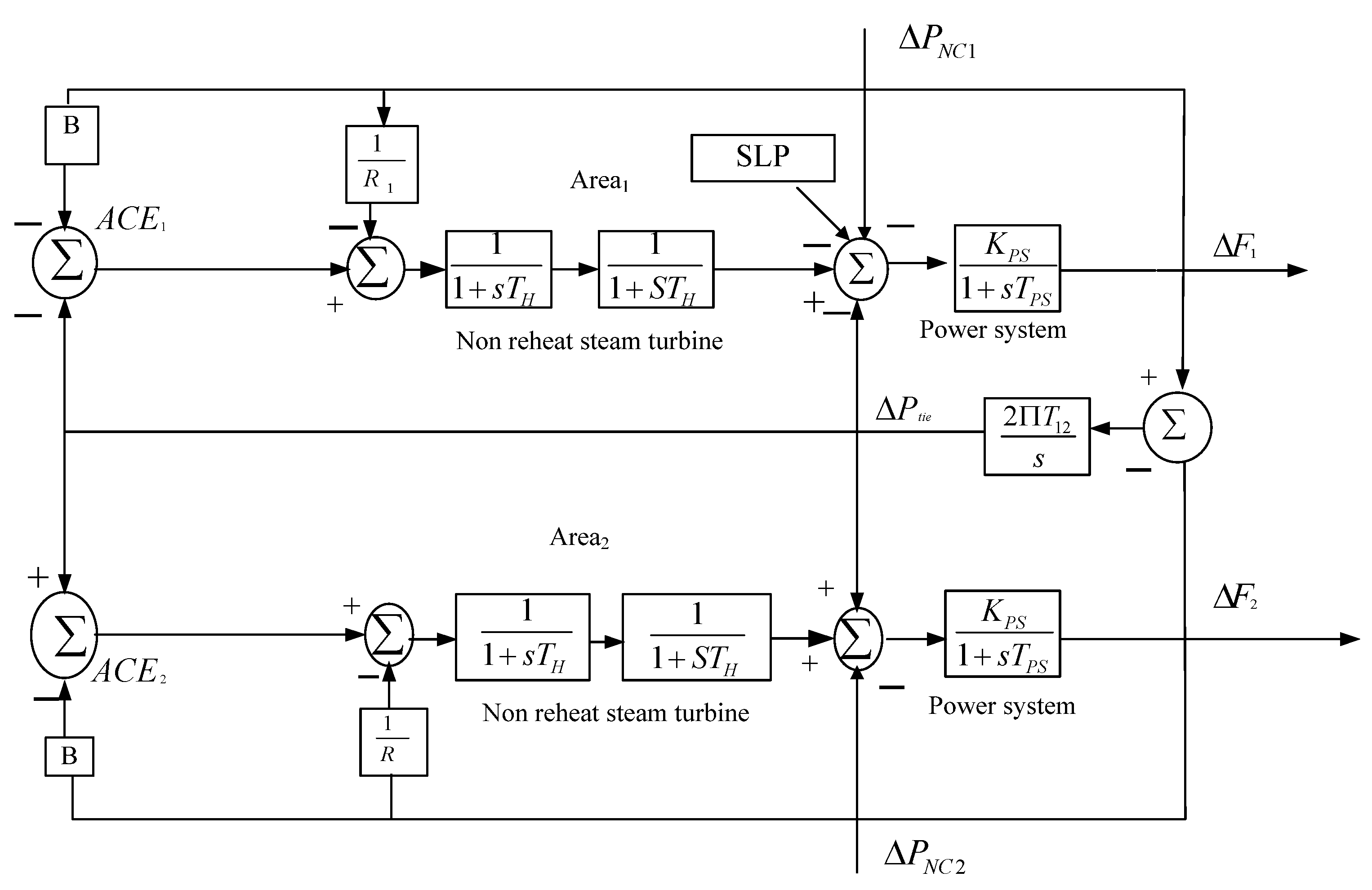
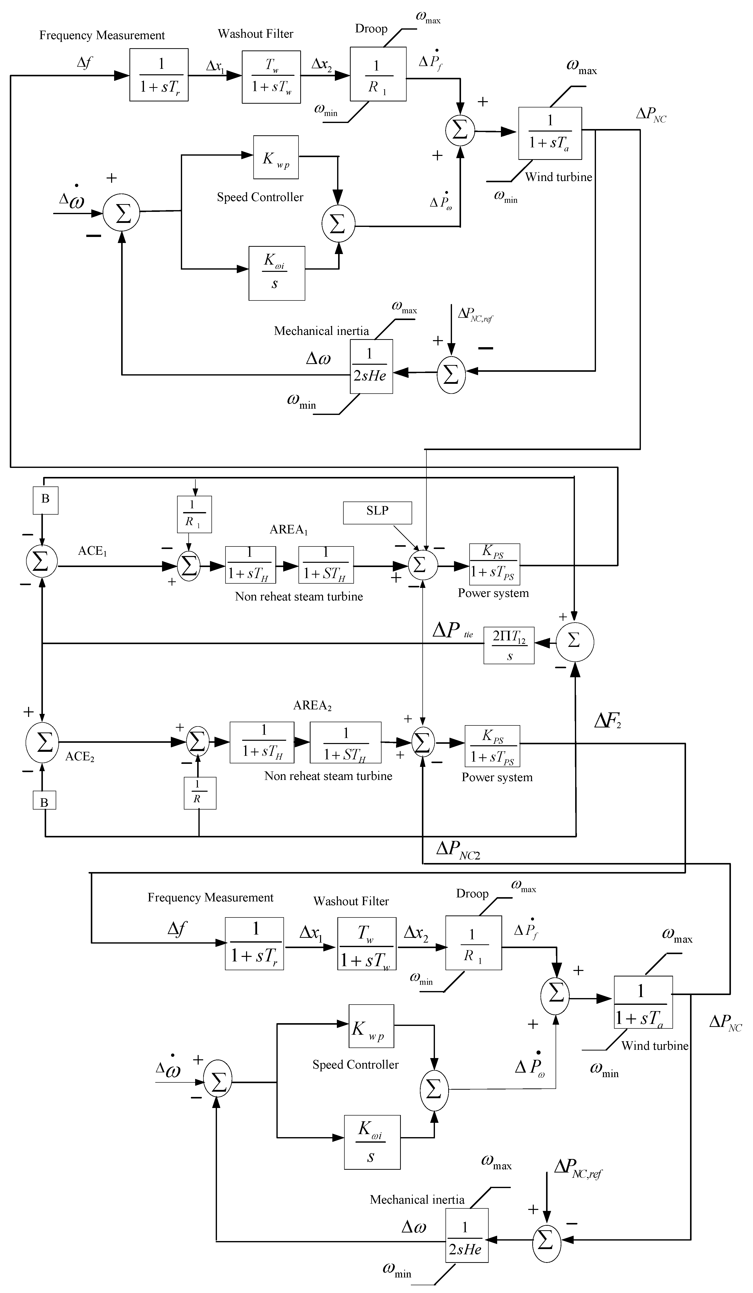
2. System Modeling and Wind Power Equation

2.1. Wind Power Equation

Wind energy is a by-product of the sun and is the indirect consequence of the incident solar energy when hot air starts to be replaced by cold air. This promotion of air or blowing of air, which is wind, starts its circulation exchange between hot air and cold zones [30]. Furthermore, the kinetic energy that exists in wind turbines will be converted to mechanical energy. Hence, the coupled wind generator in the wind turbine generates electricity. The expression of available power is given by Equation (1) [31].
P = 1 2 ρ ν 3
The actual electricity produced by wind is to be determined by knowing the power coefficient. It shows how efficiently the wind turbines convert the energy to electricity. It is simply the ratio of the output power of wind and the input power of wind, and 0.593 (59.3%) is its maximum theoretical limit. It is also known as the Betz limit. The total wind is not converted to useful energy and only 40–60% of it is extracted and is known to be the Betz limit, which is given in Equation (2).
P = 1 2 ρ A C p ν 3

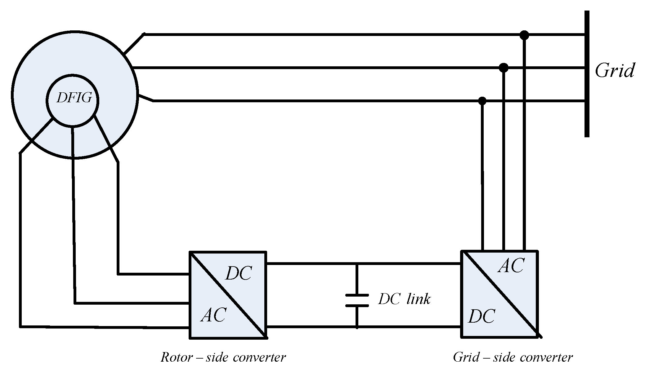
2.2. DFIG Wind Turbine

The type of generator found in DFIG wind turbines are induction generators and are composed of stator and rotor. The sinusoidal winding in the rotor and stator is distributed and displaced by 120° with phases a, b, and c. Figure 1 shows the schematic model of a DFIG connected to the grid. The wound-type stator is connected to the grid, and the rotor is connected to the grid via converter. This has the advantage of obtaining a reference voltage [32,33].
In DFIG wind generators, the rotor is connected to the grid via a back-to-back three-phase converter. This converter consists of a rotor side converter (RSC), direct current link, and grid side converter (GSC) [34]. The control of both active power generation of the DFIG and reactive power generation or voltage control is carried out by using the RSC shown in Figure 1. Similarly, the grid side converter (GSC) is involved in frequency regulation so that it guarantees power exchange between the generator and the network through the machine rotor by keeping the direct current-link (DClink) voltage constant. The GSC will absorb power from the network (DC link voltage drops) or inject power into it (DC link voltage increases). Both GSC and RSC are responsible for controlling and managing the generated power in order to take action in response to a frequency imbalance [35]. DFIGs are widely used in wind power plants because of their capability to decouple control of real and reactive power. Researchers have used the control capability of DFIG to damp power system oscillations. However, in other studies, it is also used to damp inter-area low-frequency oscillations [36]. The required reactive power injected by the DFIG into the grid is optimally shared between the RSC and GSC to minimize the back-to-back converter apparent power. It is used to determine the required reactive power that should be optimally injected into the grid by the RSC and GSC in stationary and dynamic control modes [37].

2.3. Control System of DFIG
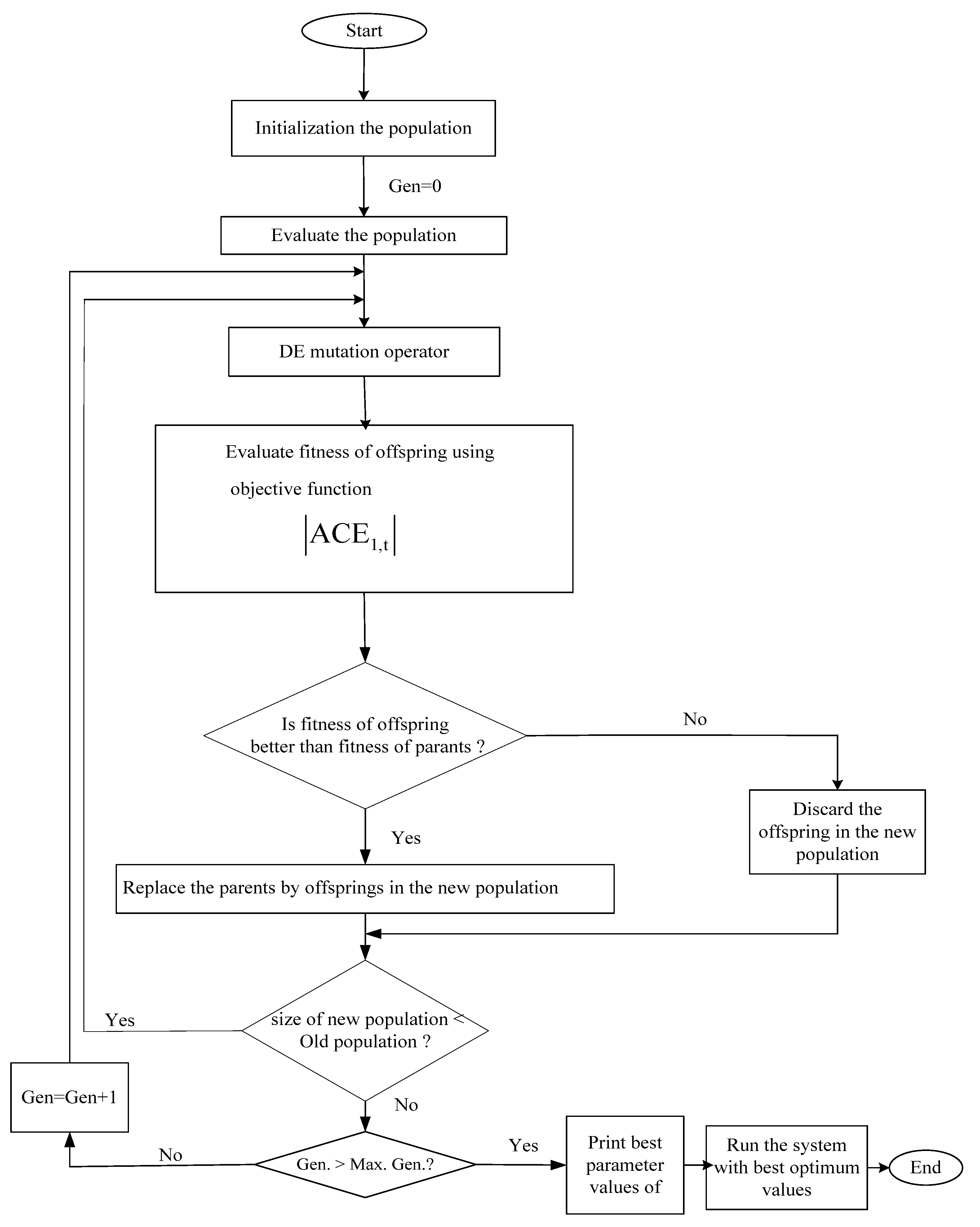
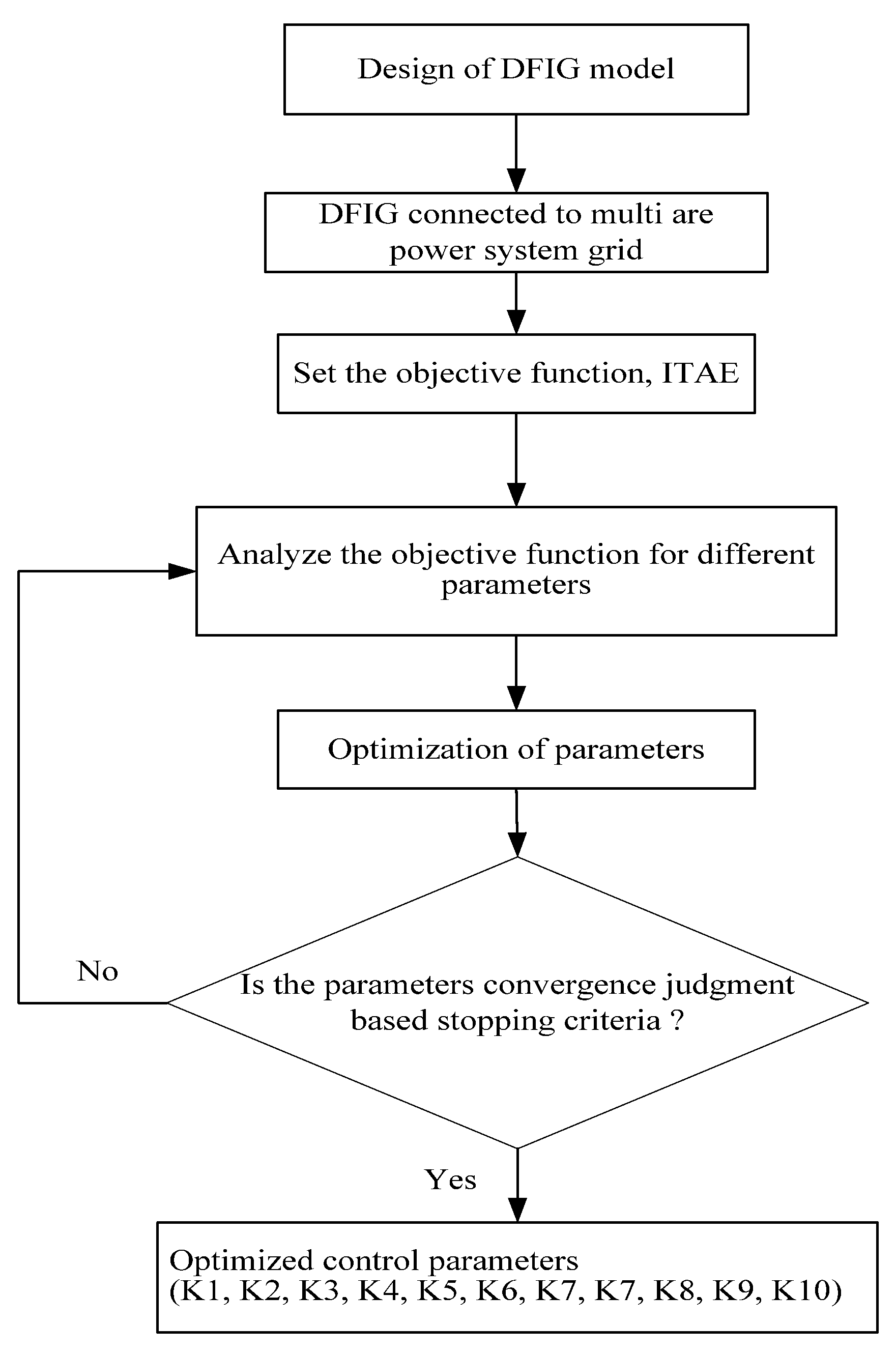
The control levels of DFIG are classified into two types. One is the faster dynamics control type and the other is the slower dynamics control type based on pitch angle control. The grid side and rotor side converters are controlled by the faster dynamics DFIG control level [33]. The DFIG model based on the inertia control is shown in Figure 2. It consists of frequency measurement, a washout filter used to remove the steady state error in frequency, droop, speed controller, wind turbine, and mechanical inertia to regulate the output of the wind turbine.
Figure 3 consists of non-reheat-type two-area power systems having 0.01 SLP in Area 1 only, and it consists of arrow indicators with symbols to integrate with Figure 2 during simulation analysis. The models used for analysis of Case Study 1, Case Study 2, and Case Study 3 are shown in Figure 4, Figure 5 and Figure 6, respectively.

3. Methodology

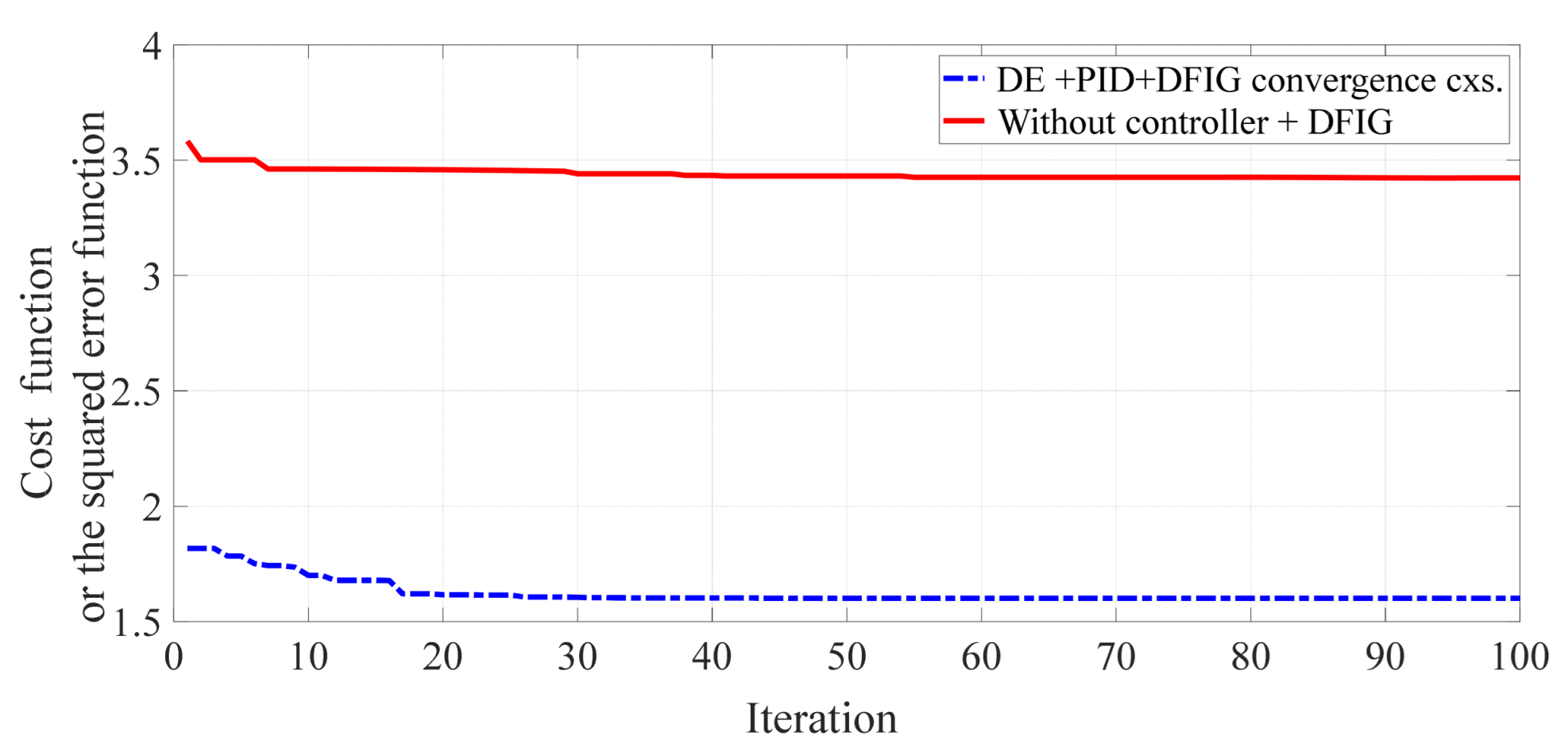
3.1. Optimization Problem

The DE was first proposed by Rainer Stron and Kenneth Price and formulated to solve optimization problems. It is used in this paper to obtain the gains of system parameter values including the controller gains of PID through the four phases of DE, namely, initialization, mutation, crossover, and selection. In the initialization steps, NP, F, and CR have been defined, and the mutation vectors will be generated in the mutation operation. In mutation, r1, r2, and r3 are randomly selected distinct integers within the range of [1, NP]. The crossover operation is performed to increase the diversity of mutation vectors. In selection, a best fit generation will be selected by comparing the target and the trial for the next iteration [40,41]. The flowchart of the DE is presented in Figure 7.
DE optimization is used in this paper to automatically adjust the controller so that it adjusts the output of the measured parameters with minimum error. Therefore, reducing the error or minimizing the error using DE optimization is the main objective. To achieve the objective of minimizing ACE, it is necessary to investigate the best type of objective function among the various types. Because of the advantage of having minimum overshoot and reduced settling time, the ITAE objective function is preferred over the others such as ITSE, ISE, and IAE [17,18,19].
I T A E = 0 T t ( | A C E 1 | + | A C E 2 | )

3.2. Overview of the Methodology

The DE algorithm is a simple and reliable method, and it is used in this work to optimize the PID controller and the DFIG gain control parameters in both areas. The major inputs for optimization are the dimension of the controller and gained parameters (D = 10) (K1, K2, K3, K4, K5, K6, K7, K8, K9, K10), population size (NP) = 50, maximum iteration = 100, scaling factor (F) = 0.5, and cross over rate (CR) = 0.98). During the optimization, the large population may increase the computation time, but it helps to obtain the accurate result. In this regard, the optimized DFIG wind turbine will improve the overall oscillation damping performance and stability of the optimized system when compared to the actual existing system. The implementation procedure of the methodology is presented with the flowchart as shown in Figure 8.

4. Results and Discussions

4.1. Case Study 1: Without Controller and without DFIG

To examine the performance, the system was simulated in various operating conditions using MATLAB R2021a version. The system parameters are presented in Appendix A. The Simulink model is interfaced with the DE code and runs 30 times repeatedly for 55 min and for 50 s simulation time at 0.01 step load perturbation. In Case Study 1, which is without the controller and without DFIG, the output values for Δ f 1 , Δ f 2 , P t i e 12 , A C E 1 , and A C E 2 are achieved. The results are presented in Figure 9a–e. From Figure 9, it is shown that the settling time is larger, ranging from 4 to 49.4 seconds. In an interconnected power system, if there is no controller, the output of frequency oscillates at a high amplitude which disturbs the steady system flow of the power system, as shown in Figure 9a–e.
As shown in Figure 9, the simulation result outputs for change in f1, change in f2, change in tie-line power, change in ACE1, and change in ACE2 in the case without controller oscillate at maximum amplitude for a longer time and settle last with a simulation time range of 50 s.

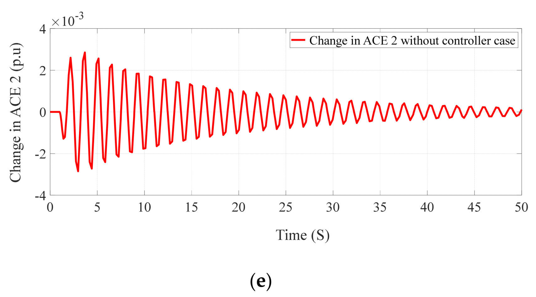
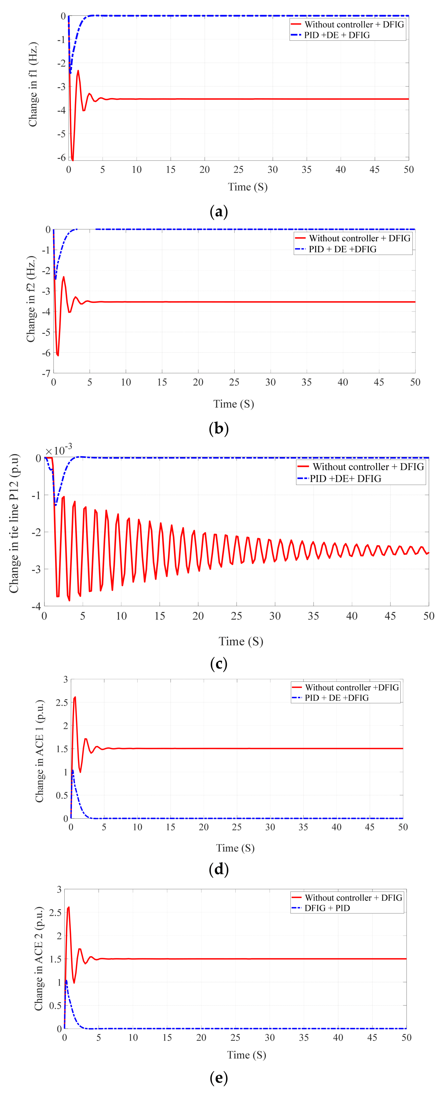
4.2. Case Study 2: Without Controller and with DFIG

In this case study, the DFIG is used with and without the controller. Just as in Case Study 1, the system has been simulated 30 times on a similar device using a population of 50 and an iteration of 100 for 1 h and 15 min. The optimized gain parameters are presented in Table 1. The output values of Case Study 2 for Δ f 1 , Δ f 2 , P t i e 12 , A C E 1 , and A C E 2 are depicted in Figure 10a–e along with the output values for Case Study 3. The time response output values of Case Study 2 for Δ f 1 , Δ f 2 , P t i e 12 , A C E 1 , and A C E 2 are presented in Table 2. From Figure 10a–e and Table 2 it is clear that, compared to Case Study 1, the overshoot, undershoot, and settling time has been reduced in Case Study 2. It is observed that the case study here with the presence of DFIG suppresses the oscillation faster than the case study without the controller, as depicted in Figure 10a–e with the dash-dot line in blue.

4.3. Case Study 3: DFIG + PID

In Case Study 3, DFIG with a DE-based PID controller is used, and the total time taken for optimization is 1h and 45 min. The gain output parameters are presented in Table 3. Compared to Case Study 1 and Case Study 2, the output is critically damped with a small rise and a settling time as shown in Figure 10. It is also observed that, with DEPID and DFIG combined, the oscillation is largely reduced, and the steady state error also became zero for the Δ f 1 , Δ f 2 , P t i e 12 , A C E 1 , and A C E 2 . The presence of the DFIG and PID controller suppresses the oscillation of the power system much faster compared to Case Study 1 and Case Study 2 and is depicted in Figure 10a–e with a solid red line. The convergence characteristics are shown in Figure 11. It shows that DE-based PID + DFIG converges at iteration 71, whereas, without the controller, plus DFIG converges at iteration 89 for the same population size of 50 and for an iteration of 100.

4.4. Discussions

The main objective of the work is to improve frequency stability using a proper penetration amount of DFIG wind turbines in a two-area power system using DE optimization techniques. In Case Study 1, the system runs without a controller and without DFIG, and the frequency oscillation is poorly damped. In Case Study 2, the DFIG is used without a controller. In Case Study 3, the DFIG with a DE-based PID controller is employed to stabilize the frequency by controlling the subsynchronous resonance oscillations for better improved frequency oscillation damping. In Table 1, K7 and K9 are the optimized gain values for the change in wind speed for DFIG wind turbines in Area 1 and Area 2, respectively. Whereas K8 and K10 are the optimized gain values for commanded power in DFIG wind turbines in Area 1 and Area 2, respectively. The time response output values for without controller plus DFIG is presented in Table 2. In Table 3, K1, K2, and K3 are the optimized controller gain values for the PID for Area 1, and K4, K5, and K6 are the optimized PID gain values for Area 2. The time response output values for DE-optimized PID plus DFIG for Case Study 3 are presented in Table 4, and it showed great improvement compared to Case Study 1 and Case Study 2. The optimized gain values K7 and K9 in Table 5 and Table 6 are the gain values for wind penetrations of 8% and 10%, respectively. The change in time response output due to 8% and 10% wind penetration is also clearly shown in Table 7 and Table 8, respectively. From the result, it is shown that better results have been achieved at 10% wind penetration compared to 8% wind penetration. In Table 9, the integral time multiplied error function for the proposed DE-based PID controller with DFIG is much less than that without the controller. Figure 12a–c depicts the performance comparison for undershoots, settling time, and overshoots, respectively, without the controller plus DFIG and DE-based PID plus DFIG. From the graph, it is clearly observed that reduced undershoot, smaller settling time, and reduced overshoot have been achieved from the DE-based PID plus DFIG method.

5. Conclusions

The role of DFIG wind turbines has been studied in the damping of power system oscillation in AGC of two equal-area interconnected systems. Three case studies have been considered to check the performance of DFIG. It reveals that with a proper controller optimization technique using DE and with the presence of DFIG in both areas, the time response parameters such as settling time, rise times, transient response, and steady state error have been greatly improved with a smaller error function and with fast convergence. The ITAE objective function error value for PID+DFIG-optimized DE is 1.6008 which is less than four times that of the objective function error value without the controller which is 6.7865. Similarly, the big transient amplitude overshoot oscillation which is observed in the case without the controller is much suppressed and damped using the proposed controller in the presence of DFIG wind turbines. Furthermore, the performance improvement in the damping of oscillation of the interconnected power systems has been examined by increasing the wind penetration level at 8% and 10%. The comparison of time response parameter values at which the wind penetration increased from 8% to 10% is given in Table 7 and Table 8, respectively. The results show a significant improvement in damping of power system oscillations corresponding to the increment in wind penetration. Generally, a DFIG wind turbine should have the ability to damp power oscillations in interconnected two-area power systems.

6. Current Limitations and Future Scope

The work presented in this paper is limited to verifying the optimization of the conventional PID controllers and the DFIG wind turbine gain parameters using simulation. The future scope of this work is to validate the proposed methodology experimentally and further implement it using artificial-intelligence-based optimization approaches such as fuzzy logic, artificial neural networks, etc.
Studies on power system oscillation damping capability using DFIG wind turbines in a two-area system are still insufficient, so appropriate design changes will be required in the future under both voltage and frequency transients at the grid side in a three- and four-area complex power system network by incorporating POD design methods in combination with PSS and FACTS controllers.

Author Contributions

S.F., R.S., B.P. and D.A. designed the problem under study, performed the simulations, and obtained the results. S.F., R.S., B.P. and D.A. wrote the paper, which was further reviewed by A.Y.A. and A.E.-S. All authors have read and agreed to the published version of the manuscript.

Funding

This research received no external funding.

Institutional Review Board Statement

Not applicable.

Informed Consent Statement

Not applicable.

Data Availability Statement

Not applicable.

Conflicts of Interest

The authors declare no conflict of interest.

Abbreviations

DFIGDouble fed induction generator
RESsRenewable energy resources
ITAEIntegral time multiplied absolute error
ISEIntegral square error
ITSE Integral time multiplied square error
IAEIntegral absolute error
DE Differential evolution
SLPStep load perturbation
ACEArea control error
ST Settling time
IPFCInterline power flow controller
ST Settling time
AGC Automatic generation control
PMSG Permanent magnet synchronous generator
DFIG Doubly fed induction generator
FSWT Fixed speed wind turbine
IG Induction generator
VSWTs Variable speed wind turbines
PSSPower system stabilizer
SMCSliding mode control
POD Power oscillations damper
MPC
RSC
GSC
Model predictive control
Rotor side converter
Grid side converter

Appendix A

Table A1. Power system parameters.
S.NoArea1Area 2DescriptionValue
1 R 1 R 2 Regulation droop2.4 Hz (p.u.MW)
2 B 1 B 2 Biasing coefficient0.425p.u.MW/Hz
3 H e 1 H e 2 Wind turbine inertia3.5 p.u.MW.sec
4 T a 1 T a 1 DFIG turbine0.2 s
5 T w 1 T w 2 Washout filter time constant6 s
6 T r 1 T r 2 Transducer time constant15 s
7 K p 1 K p 2 Power system gain120 Hz (p.u.MW)
8 T h 1 T h 2 Governor time constant0.08 s
9 T t 1 T t 2 Turbine time constant0.3 s
10 T p 1 T p 1 Power system time constant20 s
11 K ω p 1 K ω p 2 DFIG proportional controller gain1
12 K ω i 1 K ω i 2 DFIG integral controller gain0.1
13 a 12 Area size ratio coefficient−1
14. T 12 Tie-line synchronizing coefficient0.0866 p.u.MW/Hz
15 ρ rho
16 v 3 velocity cubem/s
17A area m 2
18Cp power coefficient

References

  1. Manzoor, S.; Bakhsh, F.I.; Mufti, M.U.D. Coordinated control of VFT and fuzzy based FESS for frequency stabilization of wind penetrated multi-area power system. Wind. Eng. 2022, 46, 413–428. [Google Scholar] [CrossRef]
  2. Tiwari, R.; Babu, N.R. Recent developments of control strategies for wind energy conversion system. Renew. Sustain. Energy Rev. 2016, 66, 268–285. [Google Scholar] [CrossRef]
  3. Doan, T.T.; Van Tran, Q. Offshore wind power-the new trend for economic development and security of island sovereignty. J. Min. Earth Sci. 2022, 63, 74–81. [Google Scholar] [CrossRef]
  4. Zare, S.G.; Alipour, M.; Hafezi, M.; Stewart, R.A.; Rahman, A. Examining wind energy deployment pathways in complex macro-economic and political settings using a fuzzy cognitive map-based method. Energy 2022, 238, 121673. [Google Scholar] [CrossRef]
  5. Jung, C.; Schindler, D. On the influence of wind speed model resolution on the global technical wind energy potential. Renew. Sustain. Energy Rev. 2022, 156, 112001. [Google Scholar] [CrossRef]
  6. Bevrani, H. Robust Power System Control; Springer: New York, NY, USA, 2014. [Google Scholar]
  7. Chowdhury, B.H.; Chellapilla, S. Double-fed induction generator control for variable speed wind power generation. Electr. Power Syst. Res. 2006, 76, 786–800. [Google Scholar] [CrossRef]
  8. Li, H.; Chen, Z. Overview of different wind generator systems and their comparisons. IET Renew. Power Gener. 2009, 2, 123–138. [Google Scholar] [CrossRef]
  9. Hughes, F.M.; Anaya-Lara, O.; Jenkins, N.; Strbac, G. Control of DFIG based wind generation for power network support. IEEE Trans. Power Syst. 2005, 20, 1958–1966. [Google Scholar] [CrossRef]
  10. Shankar, R.; Pradhan, S.R.; Chatterjee, K.; Mandal, R. A comprehensive state of the artliterature survey on LFC mechanism for power systems. Renew. Sustain. Energy Rev. 2017, 76, 185–207. [Google Scholar] [CrossRef]
  11. Yousef, H.A.; Al-Kharusi, K.; Albadi, M.H.; Hosseinzadeh, N. Load frequency control of a multi-area power system: An adaptive fuzzy logic approach. IEEE Trans. Power Syst. 2014, 29, 1822–1830. [Google Scholar] [CrossRef]
  12. Liu, J.; Yao, Q.; Hu, Y. Model predictive control for load frequency of hybrid power system with wind power and thermal power. Energy 2019, 172, 555–565. [Google Scholar] [CrossRef]
  13. Xu, D.; Liu, J.; Yan, X.G.; Yan, W. A novel adaptive neural network constrained control for a multi-area interconnected power system with hybrid energy storage. IEEE Trans. Ind. Electron. 2018, 65, 6625–6634. [Google Scholar] [CrossRef]
  14. Kushwaha, V.; Pandey, K.; Sehrawat, S.; Sharma, D. Adaptive neuro-fuzzy based load frequency controller for three area inter-connected hydrothermal power system. In Proceedings of the 2nd International Innovative Applications of Computational Intelligence on Power, Energy and Controls with their Impact on Humanity (CIPECH), Ghaziabad, India, 18–19 November 2016; pp. 34–38. [Google Scholar] [CrossRef]
  15. Li, H.; Wang, X.; Xiao, J. Adaptive event-triggered load frequency control for interconnected microgrids by observer-based sliding mode control. IEEE Access 2019, 7, 68271–68280. [Google Scholar] [CrossRef]
  16. Lu, K.; Zhou, W.; Zeng, G.; Zheng, Y. Constrained population extremal optimization-based robust load frequency control of multi-area interconnected power system. Int. J. Electr. Power Energy Syst. 2019, 105, 249–271. [Google Scholar] [CrossRef]
  17. Feleke, S.; Satish, R.; Tatek, W.; Abdelaziz, A.Y.; El-Shahat, A. DE-Algorithm-Optimized Fuzzy-PID Controller for AGC of Integrated Multi Area Power System with HVDC Link. Energies 2022, 15, 6174. [Google Scholar] [CrossRef]
  18. Raju, M.; Saikia, L.C.; Sinha, N. Load frequency control of a multi-area system incorporating distributed generation resources, gate controlled series capacitor along with high-voltage direct current link using hybrid ALO-pattern search optimised fractional order controller. IET Renew. Power Gener. 2019, 13, 330–341. [Google Scholar] [CrossRef]
  19. Panwar, A.; Sharma, G.; Nasiruddin, I.; Bansal, C.R. Frequency stabilization of hydro–hydro power system using hybrid bacteria foraging PSO with UPFC and HAE. Electr. Power Syst. Res. 2018, 161, 74–85. [Google Scholar] [CrossRef]
  20. Tan, A.; Lin, X.; Sun, J.; Lyu, R.; Li, Z.; Peng, L.; Khalid, M.S. A novel DFIG damping control for power system with high wind power penetration. Energies 2016, 9, 521. [Google Scholar] [CrossRef]
  21. Zuo, J.; Li, Y.; Shi, D.; Duan, X. Simultaneous robust coordinated damping control of power system stabilizers (PSSs), static var compensator (SVC) and doubly-fed induction generator power oscillation dampers (DFIG PODs) in multimachine power systems. Energies 2017, 10, 565. [Google Scholar] [CrossRef]
  22. Du, W.; Chen, X.; Wang, H. DFIG oscillation modes causing strong dynamic interactions to degrade the damping of power system low-frequency electromechanical oscillations. Electr. Power Compon. Syst. 2019, 47, 288–300. [Google Scholar] [CrossRef]
  23. He, P.; Arefifar, S.A.; Li, C.; Wen, F.; Ji, Y.; Tao, Y. Enhancing oscillation damping in an interconnected power system with integrated wind farms using unified power flow controller. Energies 2019, 12, 322. [Google Scholar] [CrossRef]
  24. Zarifakis, M.; Coffey, W.T.; Kalmykov, Y.P.; Titov, S.V.; Byrne, D.J.; Carrig, S.J. Active damping of power oscillations following frequency changes in low inertia power systems. IEEE Trans. Power Syst. 2019, 34, 4984–4992. [Google Scholar] [CrossRef]
  25. Odoh, T.E.; Sabo, A.; Wahab, N.I.A. Mitigation of Power System Oscillation in a DFIG-Wind Integrated Grid: A Review. Appl. Model. Simul. 2022, 6, 134–149. [Google Scholar]
  26. Debouza, M.; Al-Durra, A. Grid ancillary services from doubly fed induction generator-based wind energy conversion system: A review. IEEE Access 2018, 7, 7067–7081. [Google Scholar] [CrossRef]
  27. Kamel, O.M.; Abdelaziz, A.Y.; Zaki Diab, A.A. Damping Oscillation techniques for wind farm DFIG integrated into inter-connected power system. Electr. Power Compon. Syst. 2020, 48, 1551–1570. [Google Scholar] [CrossRef]
  28. Carreras, B.; Reynolds Barredo, J.M.; Dobson, I.; Newman, D.E. Validating the OPA cascading blackout model on a 19402 bus transmission network with both mesh and tree structures. Hawaii Int. Conf. Syst. Sci. 2019. [Google Scholar] [CrossRef]
  29. Faza, A. A probabilistic model for estimating the effects of photovoltaic sources on the power systems reliability. Reliab. Eng. Syst. Saf. 2018, 171, 67–77. [Google Scholar] [CrossRef]
  30. Civelek, Z.; Çam, E.; Lüy, M.; Mamur, H. Proportional–integral–derivative Parameter Optimisation of Blade Pitch Controller in Wind Turbines by a New Intelligent Genetic Algorithm. IET Renew. Power Gener. 2016, 10, 1220–1228. [Google Scholar] [CrossRef]
  31. Macedo, A.V.A.; Mota, S.W. Wind turbine pitch angle control using fuzzy logic. In Proceedings of the 2012 Sixth IEEE/PES Transmission and Distribution: Latin America Conference and Exposition (T&D-LA), Montevideo, Uruguay, 3–5 September 2012. [Google Scholar] [CrossRef]
  32. Imtiyaz, T.; Bakhsh, F.; Jain, A. Intelligent Modelling and Analysis of Direct Torque Control-Space Vector Modulation of Doubly Fed Induction Generator (DFIG). Intell. Data Anal. Power Energy Syst. 2022, 802, 45–59. [Google Scholar] [CrossRef]
  33. Abo-Khalil, A.G.; Alghamdi, A.S.; Eltamaly, A.M.; Al-Saud, M.S.; RP, P.; Sayed, K.; Bindu, G.R.; Tlili, I. Design of state feedback current controller for fast synchronization of DFIG in wind power generation systems. Energies 2019, 12, 2427. [Google Scholar] [CrossRef]
  34. Tang, Y.; He, H.; Ni, Z.; Wen, J.; Sui, X. Reactive power control of grid-connected wind farm based on adaptive dynamic programming. Neurocomputing 2014, 125, 125–133. [Google Scholar] [CrossRef]
  35. Gomez, L.A.; Lourenço, L.F.; Grilo, A.P.; Salles, M.B.; Meegahapola, L.; Sguarezi Filho, A.J. Primary frequency response of microgrid using doubly fed induction generator with finite control set model predictive control plus droop control and storage system. IEEE Access 2020, 8, 189298–189312. [Google Scholar] [CrossRef]
  36. Knuppel, T.; Nielsen, J.N.; Jensen, K.H.; Dixon, A.; Ostergaard, J. Power oscillation damping controller for wind power plant utilizing wind turbine inertia as energy storage. In Proceedings of the IEEE Power & Energy Society General Meeting, Detroit, MI, USA, 24–29 July 2011. [Google Scholar]
  37. Rahimi, M. Coordinated control of rotor and grid sides converters in DFIG based wind turbines for providing optimal reactive power support and voltage regulation. Sustain. Energy Technol. Assess. 2017, 20, 47–57. [Google Scholar] [CrossRef]
  38. Ibraheem, N.R.K.; Sharma, G. Study on participation dynamic of wind turbines in automatic generation control of power systems. Electr. Power Compon. Syst. 2015, 43, 44–55. [Google Scholar] [CrossRef]
  39. Malik, H.; Iqbal, A.; Joshi, P.; Agrawal, S.; Bakhsh, F.I. Metaheuristic and Evolutionary Computation: Algorithms and Applications; Springer: Berlin/Heidelberg, Germany, 2021. [Google Scholar] [CrossRef]
  40. Centeno-Telleria, M.; Zulueta, E.; Fernandez-Gamiz, U.; Teso-Fz-Betoño, D.; Teso-Fz-Betoño, A. Differential evolution optimal parameters tuning with artificial neural network. Mathematics 2021, 9, 427. [Google Scholar] [CrossRef]
  41. Storn, R.; Price, K. Differential evolution–a simple and efficient heuristic for global optimization over continuous spaces. J. Glob. Optim. 1997, 11, 341–359. [Google Scholar] [CrossRef]
Figure 1. Converter controller configuration of DFIG [32].
Sustainability 15 04751 g001
Figure 2. DFIG model based on inertial control [38].
Sustainability 15 04751 g002
Figure 3. Two-area transfer function model of interconnected system [39].
Sustainability 15 04751 g003
Figure 4. Two-area power system without controller.
Sustainability 15 04751 g004
Figure 5. Two-area power system without controller and with DFIG wind turbines in both areas.
Sustainability 15 04751 g005
Figure 6. Two-area power system with controller and with DFIG wind turbines in both areas.
Sustainability 15 04751 g006
Figure 7. Flow chart of DE.
Sustainability 15 04751 g007
Figure 8. Flowchart for implementation procedure.
Sustainability 15 04751 g008
Figure 9. Output responses (a) Δ f 1 (b) Δ f 2 , (c) P t i e 12 , (d) A C E 1 , (e) A C E 2 for Case Study 1.
Sustainability 15 04751 g009aSustainability 15 04751 g009b
Figure 10. Comparison of time responses for Case Studies 2 and 3: (a) Δ f 1 (b) Δ f 2 , (c) P t i e 12 , (d) A C E 1 , (e) A C E 2 .
Sustainability 15 04751 g010
Figure 11. Comparison of convergence characteristics for Case Study 2 and Case Study 3.
Sustainability 15 04751 g011
Figure 12. Performance comparison: (a) Undershoot. (b) Settling time. (c) Overshoot for without controller +DFIG and DE-based PID + DFIG.
Sustainability 15 04751 g012
Table 1. Optimum controller gains for without controller +DFIG-optimized DE.
Objective FunctionOptimum Controller Gains
ITAEK7K8K9K10
2.99991.83062.97350.9999
Table 2. Time response output values using without controller + DFIG.
Measured ParametersRise TimeSTUSOS
Change in f10.16494.1152−6.1514−2.3269
Change in f20.16494.0752−6.1514−2.3117
Change in p10.303649.3891−0.00390.0010
Change in ACE10.16524.10760.99112.6143
Change in ACE20.16464.08300.98042.6143
Table 3. Optimum controller gains for PID+DFIG-optimized DE.
Objective FunctionOptimum Controller Gains
ITAEK1K2K3K4K5K6K7K8K9K10
2.39612.99990.99992.40052.99990.99992.67842.99992.84511.0257
Table 4. Time response output values for PID+DFIG-optimized DE simulation case.
Measured ParametersRise TimeSTUSOS
Change in f11.9405 × 10-42.6540−2.45140.0084
Change in f21.9405 × 10-42.6616−2.45100.0082
Change in p10.01424.8464−0.00130.0000
Change in ACE12.0097 × 10-42.6602−0.00361.0419
Change in ACE21.9082 × 10-42.6554−0.00361.00416
Table 5. Optimum controller gains for PID+ DFIG-optimized DE at 8% increase in wind penetration.
Objective FunctionOptimum Controller Gains
ITAEK1K2K3K4K5K6K7K8K9K10
2.3961 2.9999 0.9999 2.4005 2.9999 0.9999 2.89272.99993.07271.0257
Table 6. Optimum controller gains for PID+DFIG-optimized DE at 10% increase in wind penetration.
Objective FunctionOptimum Controller Gains
ITAEK1K2K3K4K5K6K7K8K9K10
2.3961 2.9999 0.9999 2.4005 2.9999 0.9999 2.94622.99993.12961.0257
Table 7. Time response output values for PID+DFIG-optimized DE at 8% increase in wind penetration.
Measured ParametersSTUSOS
Change in f12.6539−2.45130.0084
Change in f22.6616−2.45090.0082
Change in p14.8413−0.00130.0000
Change in ACE12.6601−0.00361.0418
Change in ACE22.6554−0.00351.0416
Table 8. Time response output values for PID+DFIG-optimized DE at 10% increase in wind penetration.
Measured ParametersSTUSOS
Change in f12.6538−2.45120.0084
Change in f22.6614−2.45080.0082
Change in p14.8411−0.00130.0000
Change in ACE12.6600−0.00361.0418
Change in ACE22.6553−0.00351.0416
Table 9. Comparison of cost function.
Analyzed MethodsITAE Objective Function Values
PID+DFIG-optimized DE1.6008
Without controller6.7865
Disclaimer/Publisher’s Note: The statements, opinions and data contained in all publications are solely those of the individual author(s) and contributor(s) and not of MDPI and/or the editor(s). MDPI and/or the editor(s) disclaim responsibility for any injury to people or property resulting from any ideas, methods, instructions or products referred to in the content.

