Abstract
In this study, we utilized nano-sized Co3O4 and reduced graphene oxides (rGOs) as composite anode materials for Li-ion batteries. The Co3O4/C composite anode was derived from ZIF67 (Zeolitic Imidazolate Framework-67) and was wrapped in rGOs through precipitation. X-ray diffraction (XRD), scanning electron microscopy (SEM), and transmission electron microscopy (TEM) were used to identify the crystal structure, phase purity, and surface morphology of the composite. The composition-optimized Co3O4/rGO/C composite anode exhibited a reversible capacity of 1326 mAh/g in the first cycle, which was higher than that of the Co3O4/C composite anode with a capacity of 900 mAh/g at a current density of 200 mA/g. Moreover, after 80 cycles, Co3O4/rGO/C maintained a capacity of 1251 mAh/g at the same current density, which was also higher than the bare Co3O4/C composite (595 mAh/g). Additionally, the Co3O4/rGO/C composite exhibited a good capacity retention of 98% after 90 cycles, indicating its excellent cycling stability and high capacity. Therefore, the Co3O4/rGO/C electrode has great potential as a promising anode material for Li-ion batteries.
1. Introduction
At present, the technology industry is booming and people’s living habits have changed. 3C products are must-have items, and intelligent functions, such as mobile Internet access, video and audio playback, and cloud information reception, make these electronic products have a large capacity for power supply. With the progress of society and the economy, the development of lithium-ion batteries (LIBs) has played an important role [1,2]. LIBs have the advantages of high-energy density, long-term cycling life, and no memory, and are widely applied in commercial energy storage devices [1,2,3,4,5,6,7,8]. Recently, graphite has been used as a commercial anode because of its easy preparation and low cost [9]. However, due to its easy exfoliation, poor rate capacity and cycling stability, low theoretical capacity (372 mAh/g), and inherent safety risk, commercial graphite materials cannot achieve the high power density goal of the new type LIBs. In order to solve these problems, transition-metal oxides (TMOs) [5,7,8], such as Co3O4 [7,8,10,11,12], ZnO [13,14], and Fe2O3, with a moderate price, have received considerable attention because of their higher reversible capacity than that of graphite-based anode materials for Li-ion batteries. Nevertheless, the disadvantages of excessive expansion and low electronic conductivity limit their applications. The over-expansion or contraction leads to the materials being easily damaged. Therefore, a higher electronic conductivity and inhibiting volume expansion and contraction are important goals in anode materials made with transition-metal oxides.
Metal–organic frameworks (MOFs) are a class of porous materials composed of metal ions or clusters linked together by organic ligands. They are typically crystalline solids with a high surface area, allowing them to adsorb gases and liquids with a high selectivity and capacity [15]. MOFs have several advantages that make them attractive for various applications, including high surface area, tunable properties, selectivity, stability, and sustainability. MOFs have an exceptionally high surface area, which allows them to adsorb a large amount of gas or liquid molecules. This property is particularly useful for gas storage, separation, and catalysis. MOFs can be synthesized with a wide range of properties, such as pore size, shape, and functionality, by varying the metal ions, ligands, and synthesis conditions. This makes them highly tunable and adaptable to different applications. MOFs can selectively adsorb specific molecules based on their size, shape, and chemical properties. This selectivity can be further enhanced by functionalizing the MOFs with specific chemical groups. MOFs are generally stable under a wide range of conditions, including high temperatures, acidic or basic environments, and exposure to moisture. This stability makes them suitable for long-term storage and use in harsh conditions. MOFs can be synthesized using sustainable and environmentally friendly processes, such as solvothermal or microwave-assisted synthesis. They can also be recycled and reused, making them a potentially eco-friendly alternative to traditional materials. These advantages make MOFs promising for a wide range of applications, including hydrogen storage [15,16], adsorption [15,17,18,19,20,21,22], separation [15,16,20], electromagnetic wave absorption [11,18,23], catalysts [15,24,25,26,27], sensing [18,28], and supercapacitors [12,29,30]. Zeolitic imidazolate frameworks (ZIFs) [31,32], a new subclass of metal–organic frameworks (MOFs) that have exceptional chemical and thermal stability, are promising and widely used MOFs for heterogeneous catalysis due to their uniform pore size and well-defined morphology.
In recent years, graphene has been described as having a large theoretical specific surface area (2630 m2/g) and high intrinsic mobility (200,000 cm2/V·s) [33], and has been used in many applications, including LIBs, supercapacitors, and computer chips. Graphene [34,35] is flexibile and has stable sites located inside individual nanotubes interconnected or with sidewall openings with curved multi-layers that facilitate Li+ diffusion. Jin et al. used a Fe-MOF/RGO composite as new promising anode materials for LIBs. The as-synthesized Fe-MOF/RGO composite anode showed superior Li storage with a reversible capacity of 1010 mAh/g after 200 cycles [36]. Yin et al. proposed an rGO coating/sandwiching Co3O4 composites fabricated by employing a conventional coprecipitation method with ZIF-67, using a rhombic dodecahedron as a template and GO as a substrate. The as-prepared rGO@Co3O4 and Co3O4-rGO-Co3O4 composites exhibited excellent electrochemical performance with high initial discharge specific capacities of 1451 and 1344 mAh/g at a current density of 100 mA/g, respectively [37]. Gao et al. successfully synthesized an Al-MOF/graphene composite by the hydrothermal method. The Al-MOF/graphene composite exhibited significantly enhanced electrochemical performances. Its capacity increased continuously from 60 to 400 mAh/g at the current density of 100 mA/g [38].
In this study, we propose a novel composite anode material for Li-ion batteries, namely Co3O4/rGO/C, which was derived from ZIF-67. The main aim of our research is to address the low conductivity and poor electrical stability issues commonly observed in transition metal oxides (TMOs). To overcome these challenges, we employ reduced graphene oxide (rGO) as a conductive and stabilizing agent, which effectively enhanced the efficiency of lithium-ion diffusion and the overall electrochemical performance of the anode material. Additionally, we believe that combining metal–organic frameworks (MOFs) with carbon-based materials holds great potential for future research in the field of battery materials.
2. Materials and Methods
2.1. Synthesis of ZIF-67 and ZIF-67/GO
A total of 1.35 g of cobalt dinitrate hexahydrate (Co(NO3)2·6H2O, 98%, SHOWA) was dissolved in 10 mL deionized water. Then, 16.5 g of 2-methylimidazole (CH3C3H2N2H, 99% ACROS) was dissolved in 70 mL deionized water under vigorous stirring at room temperature overnight. The product was collected by centrifugation, washed three times with methyl alcohol, and finally dried at 80 °C for 12 h.
2.2. Synthesis of ZIF-67/GO
A total of 0.25 g of graphene oxide was placed in 250 mL ethanol with 0.25 g of CTAB (hexadecyl-trimethyl-ammonium bromide) and stirred for 10 min. The above-mentioned solution and 0.75 g of ZIF-67 were stirred vigorously on a hotplate at 280 °C and 280 rpm for 1 h. The powder was collected by centrifugation, washed several times with alcohol, and finally dried at 80 °C for 12 h.
2.3. Synthesis of Co3O4/C and Co3O4/rGO/C Composite
Alumina crucibles loaded with ZIF-67 and ZIF-67/GO powders were placed in a tube furnace and heated to 500 °C at a rate of 5 °C min−1 and maintained for 4 h under an argon atmosphere. Next, three samples in different alumina crucibles were placed in a box furnace and heated to 350 °C at a heating rate of 5 °C min−1 and maintained for 4 h under air atmosphere.
2.4. Characterizations
All the synthesized samples were examined using powder X-ray diffraction (XRD, Bruker D8 Advance Eco) with Cu Kα radiation (λ = 1.5418 Å). The surface morphology of Co3O4/C and Co3O4/rGO/C was analyzed by scanning electron microscopy (SEM, Hitachi H-7100). High-resolution transmission electron microscopy (HR-TEM) images were taken on JEOL JEM2000FX with the acceleration voltage of 200 kV.
2.5. Electrochemical Measurements
Electrochemical measurements were characterized by the CR2032-type coin cells. The electrodes were prepared by coating a slurry containing 70 wt.% active material, 20 wt.% Super P (Carbon black from Taipei City, Taiwan, Maxwave Co., Ltd., 40 nm), and 10 wt %. PVDF (Polyvinylidene fluoride). The slurry was coated onto a 10 μm copper foil and dried at 80 °C in an oven. The resulting electrodes were then pressed, punched (14 mm in diameter), and dried at 120 °C for 8 h in a vacuum system to remove any residual water. Coin-type cell batteries were assembled in an Ar-gas-filled glove box with H2O and O2 content at <0.5 ppm using lithium foil as the counter electrode, 1 M LiPF6 in a 30 wt.% ethylene carbonate (EC) and 58 wt.% diethyl carbonate (DEC) as the electrolyte solution with 2 wt.% vinylene carbonate and 10 wt.% fluoroethylene carbonates (FEC) as additives. The separators used were Celgard 2325®. Cycling stability tests were conducted using AcuTech System in a voltage window of 0.05 V to 1.5 V at room temperature. The electrochemical performance of the working electrodes was investigated using cyclic voltammetry (CV) (CH Instruments Analyzer CHI 6273E) in a voltage window of 0.05 to 1.5 V with a scan rate of 0.1 mV·s−1. Electrochemical impedance spectroscopy (EIS) measurements were taken using a CH Instruments Analyzer (CHI 6273E) with a perturbation amplitude of 5 mV and a frequency range between 105 Hz and 10 mHz.
3. Results and Discussion
Our strategy for preparing the Co3O4/rGO/C composite is schematically described in Figure 1. Firstly, we synthesized the ZIF-67 crystals in an aqueous solution and the graphene oxide was dispersed in the aqueous solution with CTAB as the dispersant. Subsequently, both were placed in a container. Eventually, the as-synthesized ZIF-67/GO was heated to 500 °C and 350 °C by annealing of ZIF-67/GO under an Ar atmosphere for 4 h at the heating rate of 5 °C min−1 and, then, at an air atmosphere for 4 h at the heating rate of 5 °C min−1.
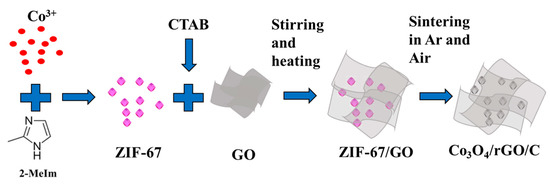
Figure 1.
Schematic representation of the as-synthesized Co3O4/rGO/C nanocomposites.
Figure 2 presents the XRD patterns of the as-synthesized GO, ZIF-67, ZIF-67/GO, and Co3O4/rGO/C nanocomposites to understand the crystal structure and phase purity of the as-synthesized ZIF-67 nanocomposites with different contents of GO. The ZIF-67/GO nanocomposites exhibited similar diffraction peaks to those of ZIF-67. The XRD patterns of the as-synthesized ZIF-67, ZIF-67/GO and ZIF-67/GO with weight ratios of 3:1 and 5:1, respectively, showed sharp and strong diffraction peaks at 2Θ of 7.2°, 10.4°, 12.8°, 14.7°, 16.43°, and 18.02°, which could be observed for all samples, corresponding to the (100), (002), (112), (022) (013), and (222) planes of ZIF-67 (CCDC-671073), respectively. The broad peak of GO in ZIF-67/GO was not observed at 2 of 11°. After annealing in air, the ZIF-67/GO composite became the Co3O4/rGO/C composite successfully and the XRD pattern of Co3O4/rGO/C displayed strong diffraction peaks of Co3O4 (JCPDS-421467) at 2 of 19°, 36.84°, 38.54°, 44.8°, and 49.07°, corresponding to (111), (220), (311), (222), and (400), respectively.
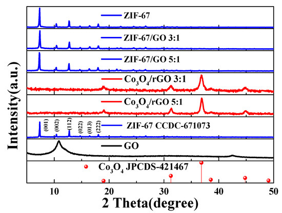
Figure 2.
The XRD patterns of the as-synthesized ZIF-67, simulated ZIF-67 (CCDC-671073), different contents of GO in the as-synthesized ZIF-67, rGO with different ratios of Co3O4, and simulated Co3O4 (JCPDS-421467).
The thermal behaviors of the Co3O4/C and Co3O4/rGO/C composites are shown in Figure 3. We performed a thermogravimetric analysis by heating the samples at a rate of 10 °C min−1 in an air atmosphere. The first weight loss during ~130 °C was attributed to the evaporation of the adsorbed moisture in the air. Subsequently, the second weight loss, of about 50.1% between 356.4 °C and 375.8 °C, corresponded to the consumption of carbon dioxide. The reduced graphene oxide contents of Co3O4/rGO/C composite could be estimated at about 8.9 wt.% by weight loss.
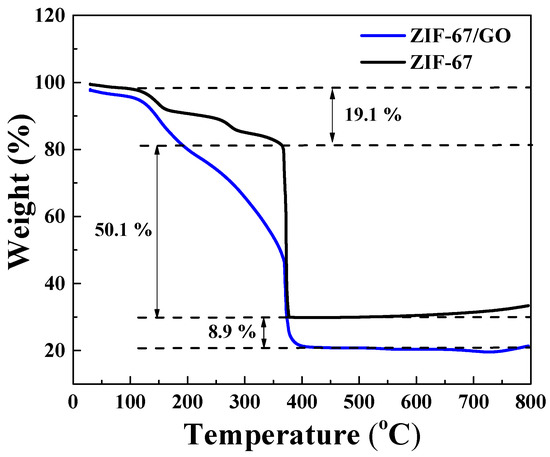
Figure 3.
Thermogravimetric analysis curves of the Co3O4/C and Co3O4/rGO/C composites under an air atmosphere at the heating rate of 10 °C min−1.
Figure 4 shows the SEM images of the Co3O4/C and Co3O4/rGO/C samples. As shown in Figure 4a, the as-synthesized Co3O4/C exhibited a particle structure with a particle size of 100–200 nm. The Co3O4/C sample was homogeneously coated by two-dimensional rGO nanosheets in Figure 4b. Flake-liked rGO nanosheets were closely wrapped on the surface of the Co3O4/C particles. The SEM image of Co3O4/rGO/C revealed that the rGO was dispersed on the Co3O4/C particles.
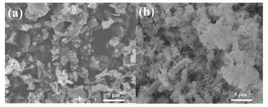
Figure 4.
SEM images of the (a) Co3O4/C and (b) Co3O4/rGO/C composites.
In order to further explore the structural information of the Co3O4/C and Co3O4/rGO/C composites, the as-prepared materials were identified by TEM characterizations. Figure 5a shows that the Co3O4 has a diameter of around 60 nm. Meanwhile, Co3O4/rGO/C was further characterized so as to observe the structure and morphology of the composite material more intuitively, as shown in Figure 5b. Additionally, these nanoparticles were dispersed on reduced graphene nanosheets. It can be seen that the structure of Co3O4 is coated with layers of carbon and was dispersed on the rGO sheets successfully. The electron diffraction rings of Co3O4/C and Co3O4/rGO/C are indexed and displayed in the inset of Figure 5a,b. The results further indicate that the as-prepared Co3O4 in these two samples was in the pure phase with a polycrystalline structure and confirm that these series of diffraction rings are indexed to the (111), (220), (311), (400), (422), (511), and (440) planes of Co3O4 in the selected-area electron diffraction (SAED) patterns.
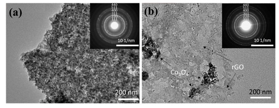
Figure 5.
TEM images of (a) Co3O4/C and (b) Co3O4/rGO/C. Insets show the SAED patterns of Co3O4/C and Co3O4/rGO/C in (a) and (b), respectively.
The specific surface area and the corresponding pore size distribution of Co3O4/C and Co3O4/rGO/C were determined from the BET measurements with N2 adsorption/desorption isotherms, as shown in Figure 6a,b. As shown in Figure 6a, the specific surface area of the Co3O4/C powder was about 61.2 m2 g−1. Additionally, the corresponding pore size distribution curve, shown in the inset of Figure 6a, exhibited an average pore size of 11.1 nm by the Barrett–Joyner–Halenda (BJH) method. The results indicate that the specific surface area of the Co3O4/rGO/C composite was 28.5 m2 g−1. The BET surface area of the Co3O4/rGO/C composite was much smaller than that of Co3O4/C. The results revel that Co3O4/C was wrapped by rGO efficiently. The pore size distribution of the Co3O4/rGO/C composite presented an average pore size of 24.15 nm, which is in the range of mesopores.
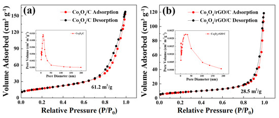
Figure 6.
Nitrogen adsorption–desorption isotherms of the (a) Co3O4/C and (b) Co3O4/rGO/C composites. Inset: the pore-size distribution of (a) Co3O4/C and (b) Co3O4/rGO/C from BJH calculation based on the desorption branch of the corresponding isotherm.
The long-term cyclic performances of the Co3O4/C and Co3O4/rGO/C samples, shown in Figure 7a,b, were conducted at the rate of 0.2 A g−1 at the voltage window of 0.05–3 V. Figure 7a depicts the discharge capacity of the Co3O4/C and Co3O4/rGO/C samples as a function of the cycle number at the current density of 0.2 A g−1 within 95 cycles. Co3O4/rGO/C electrodes have the high specific capacity of 1321 mAh g−1 at the beginning of the cycle. The capacity of the Co3O4/rGO/C electrode increased considerably that was obviously observed. The reasons for this may be due to: (1) The activation process improved LiB diffusion kinetics, causing a high accessibility for LiB insertion/extraction from materials; and (2) the adjustment action and improvement of Li+ accessibility in the electrode, and the conversion of crystalline construction to amorphous structure of Co3O4/rGO/C. Figure 7b displays the rate capability of Co3O4/C and Co3O4/rGO/C electrodes at different current density. The Co3O4/rGO/C electrode exhibited the reversible specific capacities of 1333, 1377, 1370, and 1283 mAh g−1 at the current densities of 0.2, 0.5, 1, and 2 A g−1, respectively. As shown in Figure 7c, the Co3O4/rGO/C electrode exhibited a more stable Coulombic retention than that of Co3O4/C during 90 cycles. Figure 7d displays the galvanostatic discharge–charge profiles of the Co3O4/rGO/C composite at the current density of 0.2 A g−1 in the voltage window between 0.01 V and 3.0 V. The initial charges and discharges capacities of the Co3O4/rGO/C electrodes were 1273 and 1680 mAh g−1, respectively. The Coulombic efficiency of the Co3O4/rGO/C electrodes in the first charge/discharge was maintained at 75.9%. The slightly capacity decline in the Co3O4/rGO/C electrodes might result from the formation of SEI between the electrolyte and the electrode material. The obvious discharge plateau of Co3O4/rGO/C at around 1.0 V during the discharge process was due to the irreversible conversion reaction of Co3O4. After 80 cycles, Co3O4/rGO/C electrodes maintained a high capacity of 1260 mAh g−1.
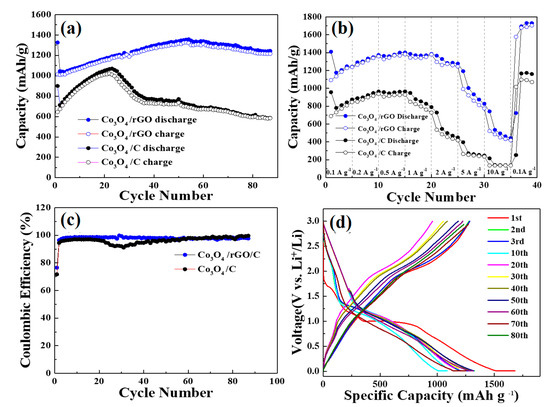
Figure 7.
(a) Cycling performance of the as-synthesized Co3O4/C and Co3O4/rGO/C composites at the current density of 0.2 A/g. (b) Rate capability tests of the as-synthesized Co3O4/C and Co3O4/rGO/C at 0.1A g−1, 0.2 A g−1, 0.5 A g−1, 1 A g−1, 2 A g−1, 5 A g−1, and 10 A g−1. (c) Coulombic efficiency of the as-synthesized Co3O4/C and Co3O4/rGO/C at the current density of 0.2 A/g. (d) Charge/discharge curves of the as-synthesized Co3O4/rGO/C at the current density of 0.2 A/g.
Figure 8a,b shows the typical CV curves of the Co3O4/C and Co3O4/rGO/C electrodes at a scan rate of 0.1 mV s−1 in the voltage range of 0.01–3.0 V for the first three cycles. During the first discharge process, shown in Figure 8a, the broad peak in ~0.79 V corresponded to the initial reduction of Co3O4 to metallic Co accompanied by the formation of Li2O and solid electrolyte interface (SEI). In the charge process, the peak at 2.1 V was ascribed to the reoxidation of metallic Co to Co3O4 and the decomposition of Li2O. The small peak located at 1.25V in the first cycle for Co3O4/rGO/C might be due to SEI formation, to which rGO contributed. The functional groups in rGO could also contribute to SEI formation during the first charging process. After two and three cycles, the charge peak shifted from 2.1 V to a higher voltage, indicating that the Co3O4/C electrodes are not sufficiently stable. As depicted in Figure 8b, the reduction peak at 0.79 V in the first anode sweep resulted from the reduction of cobalt ion and the generation of the irreversible formation of the solid electrolyte interface (SEI) film [39]. Meanwhile, there was an intense peak at around 2.1 V in the charge process, corresponding to the initial oxidation of metallic Co to Co3O4 accompanied by the formation of metallic Li in the first cycle. From the second and third cycles, the reduction peaks shifted from 0.79 V to 1.17 V, when the oxidation peaks remained unchanged. The oxidation and reduction peaks of the Co3O4/rGO/C composites during the second to third cycles presented similar voltages, indicating a high reversibility and low polarization, after introducing rGOs, in improving cycling and structure stability.
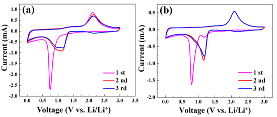
Figure 8.
Cyclic voltammograms of the Co3O4/C (a) and Co3O4/rGO/C (b) electrodes at the scan rate of 0.1 mV s−1 in the voltage range of 0.01–3 V vs. Li/Li+.
As shown in Figure 9a,b, the electrochemical impedance spectral (EIS) measurements of Co3O4/C and Co3O4/rGO/C involved the Nyquist plots and Randles plots of the electrodes. AC impedances are exhibited in Nyquist plots for Co3O4/C and Co3O4/rGO/C in Figure 9a. All of the Nyquist plots exhibited a depressed semicircle in the middle- and high-frequency regions and an oblique line in the low-frequency region. Furthermore, a straight line in the low-frequency region indicates ion diffusion in the solid electrode, as previously reported [40]. The equivalent circuit for the Nyquist plots is shown in the inset of Figure 9a, where RSEI, Rct, , and D represent the SEI resistance, charge transfer resistance, the slope of Randles plots, and diffusion impedance of the electrode systems, shown in Table 1, respectively. The RSEI of the Co3O4/C electrodes was 201.1 Ω and that of the Co3O4/rGO/C electrodes was 98.9 Ω The impedance of the SEI layer of the Co3O4/C electrodes had an about two-times higher value than that of the Co3O4/rGO/C electrodes. The rGO coating may help to stabilize the formation of SEI on the surface of the electrode during the charge and discharge processes. The RCT of Co3O4/C was 21.4 Ω and that of Co3O4/rGO/C electrodes was 12.1 Ω. The relative lower Rct of the Co3O4/rGO/C electrodes could be ascribed to the higher conductivity of the Co3O4/rGO/C electrodes. As can be seen, the slopes of the Randles plots () of the Co3O4/rGO/C and Co3O4/C electrodes were 19.28 Ω and 13.15 Ω, respectively. Finally, the diffusion coefficient (DLi+) of the Co3O4/rGO/C electrodes was 2.11 × 10⁻¹⁴ cm2 s−1 and that of the Co3O4/C electrodes was 9.83 × 10⁻¹⁵ cm2 s−1. The results reveal that the Co3O4/rGO/C electrodes had higher values than those of Co3O4/C electrodes by 9.83 × 10⁻¹⁵ cm2 s−1 due to the rGO coating.
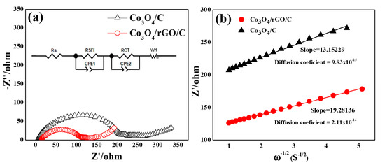
Figure 9.
(a) Nyquist plots for the Co3O4/C and Co3O4/rGO/C electrodes at 2.5 cycles. (b) The relationship lines between Z′ vs. ω1/2 in the low-frequency region of the Co3O4/C and Co3O4/rGO/C electrodes. Inset in (a) shows the corresponding Randles-equivalent circuit of the electrodes.

Table 1.
The RSEI, RCT, , and diffusion coefficient of Li+ in the Co3O4/C and Co3O4/rGO/C electrodes.
The Randles plots of Z′ versus ω−1/2 of the Co3O4/C and Co3O4/rGO/C electrodes are shown in Figure 9b and can be calculated using the following equation [5]:
In Equation (1), R, T, A, n, F, and C represent the gas constant (8.314 J mol−1 K−1), absolute temperature (298.5 K), the apparent surface area of the electrode (3.14 cm2), the number of electrons participating in the redox reaction per molecule (one electron), the Faraday constant (96,486 C/mol−1), and the concentration of lithium ions in the shuttle (10−3 mol cm−3), respectively. Each of these parameters has a specific value. The final parameter, ω, is the Warburg coefficient, which is equal to the slope of the line fitted to the plot of Z′ versus ω−1/2 at a low frequency, as shown in Figure 9b. The results indicate that the smaller slope was obtained from the Co3O4/rGO/C electrodes, which shows the greater Li-ion diffusivity in the Co3O4/rGO/C electrodes. The diffusion coefficient of the Co3O4/rGO/C electrodes had an about two-times higher value than that of the Co3O4/C electrodes, corresponding to the Nyquist plots for the Co3O4/C and Co3O4/rGO/C electrodes. This result of the AC impedance is consistent with the excellent cycling stability and ionic conductivity of the Co3O4/rGO/C composite.
The Galvanostatic Intermittent Titration Technique (GITT) measurements of the as-prepared Co3O4/C and Co3O4/rGO/C electrodes are shown in Figure 10. Figure 10a,b presents the GITT profiles of the Co3O4/C and Co3O4/rGO/C electrodes at the current density of 0.2 A g−1. The diffusion coefficient of Co3O4/C and Co3O4/rGO/C can be calculated using the following equation [41,42,43,44]:
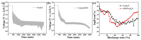
Figure 10.
GITT of the (a) Co3O4/C and (b) Co3O4/rGO/C electrodes in the first cycle. (c) Li+ diffusion coefficient at different discharge states.
In Equation (2), the symbol τ represents the duration of the current pulse in seconds (s), nm represents the number of moles in the system (mol), Vm represents the molar volume of the electrode in cubic centimeters per mole (cm3/mol), and S represents the contact area between the electrode and electrolyte in square centimeters (cm2). ΔEs refers to the steady-state voltage change due to the current pulse, while ΔEt represents the voltage change during the constant current pulse, with the IR drop eliminated. The discharge time (t) was 600 s (s) and the rest time (s) was 2400. The entire discharging time was regarded as a discharging state from 0 to 1. The diffusion of the Co3O4/rGO/C electrodes at 8%–17% and 20%–55 % discharge states was slightly lower than that of Co3O4/C because the electrolyte of Co3O4/C, infiltrated in the electrodes, is faster than the electrolyte of Co3O4/rGO/C initially, indicating that Li+-ion diffusion of the Co3O4/C electrodes were higher than those of Co3O4/rGO/C before 57.6 % of the discharge state. These results are shown in Figure 6a. In the cycling performance of the as-synthesized Co3O4/C and Co3O4/rGO/C electrodes at 0.2 A/g, the increase trend of the capacity of the Co3O4/C electrode was higher than that of the Co3O4/rGO/C electrode within 23 cycles. However, after 60 cycles, the diffusion coefficient of lithium ions in the Co3O4/rGO/C electrodes was higher than that of the Co3O4/C electrodes after 57.6% of the discharge state. The dense rGO layer might be penetrated and activated after 60 cycles; thus, the reversible capacity and diffusivity of the Li-ion in the Co3O4/rGO/C electrodes were dramatically enhanced.
We believe that rGO can significantly enhance the electrochemical properties in Co3O4/C composite materials due to three main reasons: (1) The nature of the elasticity of rGO can alleviate the severe volume expansion and contraction of the Co3O4 active material throughout the charging and discharging processes, stabilizing the electrode structure of Co3O4; (2) By adding GO during the synthesis of Co3O4/C, Co3O4 aggregation during the nucleation process can be suppressed, enabling the formation of nano-sized dispersion and resulting in a more uniform distribution of Co3O4 and conductive carbon materials; and (3) the rGO itself can enhance the three-dimensional conductive network, allowing for smoother conductive pathways during the charging and discharging process and resulting in a significant improvement in the rate performance, reversible capacity, and cycle life of the Co3O4/C composite anode.
4. Conclusions
In this study, the Co3O4/rGO/C composite anode material was synthesized using a sedimentation method and tested for its electrochemical performance in lithium-ion batteries. The composite material exhibited a higher capacity of 1244 mA/g compared to Co3O4/C (584 mAh g−1) after 90 cycles at 2 A/g. The stability of the composite was also tested at different current rates, showing superior stability at 5 A/g and 10 A/g. The Randles plots and GITT analyses suggested that the rGO in the composite facilitated the diffusion of Li+ and improved insertion/desertion in lithium ions. Overall, the Co3O4/rGO/C composite exhibited a better stability and conductivity and has potential as an anode material in LiBs.
Author Contributions
Y.-X.G. wrote the paper; W.-R.L. and C.-T.H. conceived and designed the experiments; C.-H.H. and Y.A.G. analyzed the data. All authors have read and agreed to the published version of the manuscript.
Funding
This research was funded by National Science of Technology Council (NSTC) grant number [NSTC 111-2622-E-033-007, 111-2811-E-033-001-MY3, 111-2221-E-033-004-MY3, and 111-2923-E-006-009] and The APC was funded by Metal Industries Research and Development Centre.
Institutional Review Board Statement
Not applicable.
Acknowledgments
The authors gratefully acknowledged the National Science of Technology Council (NSTC), project grant no. NSTC 111-2622-E-033-007, 111-2811-E-033-001-MY3, 111-2221-E-033-004-MY3, and 111-2923-E-006-009.
Conflicts of Interest
The authors declare no conflict of interest.
References
- Yue, H.; Shi, Z.; Wang, Q.; Gao, Z.; Dong, H.; Qiao, Y.; Yin, Y.; Yang, S. MOF-Derived Cobalt-Doped ZnO@C Composites as a High- Performance Anode Material for Lithium-Ion Batteries. Appl. Mater. Interfaces 2014, 16, 17067–17074. [Google Scholar] [CrossRef] [PubMed]
- Han, Y.; Qi, P.; Feng, X.; Li, S.; Fu, X.; Li, H.; Chen, Y.; Zhou, J.; Li, X.; Wang, B. In Situ Growth of MOFs on the Surface of Si Nanoparticles for Highly Efficient Lithium Storage: Si@MOF Nanocomposites as Anode Materials for Lithium-Ion Batteries. Appl. Mater. Interfaces 2015, 55, 2178–2182. [Google Scholar] [CrossRef] [PubMed]
- Zhang, J.; Chu, R.; Chen, Y.; Jiang, H.; Zeng, Y.; Chen, X.; Zhang, Y.; Huang, N.M.; Guo, H. MOF-derived Transition Metal Oxide Encapsulated in Carbon Layer as Stable Lithium Ion Battery Anodes. J. Alloys Compd. 2019, 797, 83–91. [Google Scholar] [CrossRef]
- Wang, K.; Pei, S.; He, Z.; Huang, L.A.; Zhu, S.; Guo, J.; Shao, H.; Wang, J. Synthesis of a Novel Porous Silicon Microsphere@carbon Core-shell Composite Via in Situ MOF Coating for Lithium-ion Battery Anodes. Chem. Eng. J. 2019, 356, 272–281. [Google Scholar] [CrossRef]
- Suna, X.; Gaoa, G.; Yanb, D.; Fenga, C. Synthesis and Electrochemical Properties of Fe3O4@MOF Core-shell Microspheres as An Anode for Lithium Ion Battery Application. Appl. Surf. Sci. 2017, 405, 52–59. [Google Scholar] [CrossRef]
- Dai, J.; Li, J.; Zhang, Q.; Liao, M.; Duan, T.; Yao, W. Co3S4@C@MoS2 Microstructures Fabricated from MOF Template as Advanced Lithium-ion Battery Anode. Mater. Lett. 2019, 236, 483–486. [Google Scholar] [CrossRef]
- Wu, R.; Qian, X.; Rui, X.; Liu, H.; Yadian, B.; Zhou, K.; Wei, J.; Yan, Q.; Feng, X.Q.; Long, Y.; et al. Zeolitic Imidazolate Framework 67-Derived High Symmetric Porous Co3O4 Hollow Dodecahedra with Highly Enhanced Lithium Storage Capability. Small 2014, 10, 1932–1938. [Google Scholar] [CrossRef]
- Qu, Q.; Gao, T.; Zheng, H.; Li, X.; Liu, H.; Shen, M.; Shao, J.; Zheng, H. Graphene Oxides-guided Growth of Ultrafine Co3O4 Nanocrystallites from MOFs as High-performance Anode of Li-ion Batteries. Carbon 2015, 92, 119–125. [Google Scholar] [CrossRef]
- An, Y.; Fei, H.; Zeng, G.; Ci, L.; Xi, B.; Xiong, S.; Feng, J. Commercial Expanded Graphite as A Low–cost, Long-cycling Life Anode for Potassium–ion Batteries with Conventional Carbonate Electrolyte. J. Power Sources 2018, 378, 66–72. [Google Scholar] [CrossRef]
- Yuana, J.; Liu, Q.; Li, S.; Lu, Y.; Jin, S.; Li, K.; Chena, H.; Zhang, H. Metal Organic Framework (MOF)-derived Carbonaceous Co3O4/Co Microframes Anchored on RGO with Enhanced Electromagnetic Wave Absorption Nerformances. Synth. Met. 2017, 228, 32–40. [Google Scholar] [CrossRef]
- Wang, Y.; Di, X.; Wu, X.; Li, X. MOF-derived Nanoporous Carbon/Co/Co3O4/CNTs/RGO Composite with Hierarchical Structure as A High-efficiency Electromagnetic Wave Absorber. J. Alloys Compd. 2020, 846, 156215. [Google Scholar] [CrossRef]
- Xie, K.; Qin, X.; Wang, Y.; Tao, H.; Wu, Q.; Yang, L.; Hu, Z. Carbon Nanocages as Supercapacitor Electrode Materials. Adv. Mater. 2012, 24, 347–352. [Google Scholar] [CrossRef] [PubMed]
- Samuel, E.; Park, C.; Kim, T.; Joshi, B.; Aldalbahi, A.; Alanzi, H.S.; Swihart, M.T.; Yoon, W.Y.; Yoon, S.S. Dodecahedral ZnO/C Framework on Reduced Graphene Oxide Sheets for High-performance Li-ion Battery Anodes. J. Alloys Compd. 2020, 834, 155208. [Google Scholar] [CrossRef]
- Zhang, H.; Wang, Y.; Zhao, W.; Zou, M.; Chen, Y.; Yang, L.; Xu, L.; Wu, H.; Cao, A. MOF-Derived ZnO Nanoparticles Covered by N-doped Carbon Layers and Hybridized on Carbon Nanotubes for Lithium-Ion Battery Anodes. ACS Appl. Mater. Interfaces 2017, 43, 37813–37822. [Google Scholar] [CrossRef] [PubMed]
- Fan, W.; Wang, X.; Xu, B.; Wang, Y.; Liu, D.; Zhang, M.; Shang, Y.; Dai, F.; Zhang, L.; Sun, D. Amino-functionalized MOFs with High Physicochemical Stability for Efficient Gas Storage/separation, Dye Adsorption and Catalytic Performance. ACS Appl. Mater. Interfaces 2018, 6, 24486–24495. [Google Scholar] [CrossRef]
- Wang, W.; Yuan, D. Mesoporous Carbon Originated from Non-permanent Porous MOFs for Gas Storage and CO2/CH4 Separation. Sci. Rep. 2014, 4, 5711. [Google Scholar] [CrossRef]
- Pan, Y.; Li, Z.; Zhang, Z.; Tong, X.S.; Li, H.; Jia, C.Z.; Liu, B.; Sun, C.Y.; Yang, L.Y.; Chen, G.J.; et al. Adsorptive Removal of Phenol from Aqueous Solution with Zeolitic Imidazolate Framework-67. J. Environ. Manag. 2016, 169, 167–173. [Google Scholar] [CrossRef]
- Xue, W.; Yang, G.; Bi, S.; Zhang, J.; Hou, Z.L. Construction of Caterpillar-like Hierarchically Structured Co/MnO/CNTs Derived from MnO2/ZIF-8@ZIF-67 for Electromagnetic Wave Absorption. Carbon 2021, 173, 521–527. [Google Scholar] [CrossRef]
- Jin, Y.; Zhao, C.; Sun, Z.; Lin, Y.; Chen, L.; Wang, D.; Shen, C. Controllable Synthesis of Isoreticular Pillared-layer MOFs: Gas Adsorption, Iodine Sorption and Sensing Small Molecules. J. Mater. Chem. A 2014, 36, 14827–14834. [Google Scholar]
- Jabbari, V.; Veleta, J.M.; Chaleshtori, M.Z.; Torresdey, J.G.; Villagrán, D. Green Synthesis of Magnetic MOF@GO and MOF@CNT Hybrid Nanocomposites with High Adsorption Capacity towards Organic Pollutants. Chem. Eng. J. 2016, 304, 774–783. [Google Scholar] [CrossRef]
- Zhang, Z.; Zhao, Y.; Gong, Q.; Li, Z.; Li, J. MOFs for CO2 Capture and Separation from Flue Gas Mixtures: The Effect of Multifunctional Sites on their Adsorption Capacity and Selectivity. Chem. Commun. 2013, 49, 653–661. [Google Scholar] [CrossRef] [PubMed]
- Canivet, J.; Fateev, A.; Guo, Y.; Coasnecd, B.; Farrusseng, D. Water Adsorption in MOFs: Fundamentals and Applications. Chem. Soc. Rev. 2014, 43, 5594–5617. [Google Scholar] [CrossRef] [PubMed]
- Zhang, K.; Xie, A.; Sun, M.; Jiang, W.; Wu, F.; Dong, W. Electromagnetic Dissipation on the Surface of Metal Organic Framework (MOF)/reduced graphene oxide (RGO) Hybrids. Mater. Chem. Phys. 2017, 199, 340–347. [Google Scholar] [CrossRef]
- Hou, S.L.; Dong, J.; Jiang, X.L.; Jiao, Z.H.; Zhao, B. Noble-Metal-Free Metal–Organic Framework (MOF) Catalyst for the Highly Efficient Conversion of CO2 with Propargylic Alcohols. Angew. Chem. 2019, 43, 577–581. [Google Scholar] [CrossRef]
- Li, B.; Zhang, Y.; Ma, D.; Li, L.; Li, G.; Li, G.; Shi, Z.; Feng, S. A Strategy toward Constructing a Bifunctionalized MOF Catalyst: Post-synthetic Modification of MOFs on Organic Ligands and Coordinatively Unsaturated Metal Sites. Appl. Mater. Interfaces 2012, 49, 220–223. [Google Scholar] [CrossRef]
- Park, K.S.; Jin, S.A.; Lee, K.H.; Lee, J.; Song, I.; Lee, B.S.; Kim, S.; Sohn, J.; Pak, C.; Kim, G.; et al. Characterization of Zeolitic Imidazolate Framework–derived Polyhedral Carbonaceous Material and its Application to Electrocatalyst for Oxygen Reduction Reaction. Electrochmical Sci. 2016, 11, 9295–9306. [Google Scholar] [CrossRef]
- García, P.G.; Müller, M.; Corma, A. MOF Catalysis in Perspective to their Homogeneous Counterparts and Conventional Solid Catalysts. Chem. Sci. 2014, 5, 2979–3007. [Google Scholar] [CrossRef]
- Zhao, S.S.; Yang, J.; Liu, Y.Y.; Ma, J.F. Fluorescent Aromatic Tag-Functionalized MOFs for Highly Selective Sensing of Metal Ions and Small Organic Molecules. Inorg. Chem. 2016, 123, 2261–2273. [Google Scholar] [CrossRef]
- Dolgopolova, E.A.; Rice, A.M.; Martin, C.R.; Shustova, N. Photochemistry and Photophysics of MOFs: Steps towards MOF-based Sensing Enhancements. Chem. Soc. Rev. 2018, 47, 4710–4728. [Google Scholar] [CrossRef]
- Hosseinian, A.; Amjad, A.; Khanmiri, R.H.; Kalhor, E.G.; Babazadeh, M.; Vessally, E. Nanocomposite of ZIF-67 Metal–organic Framework with Reduced Graphene Oxide Nanosheets for High-performance Supercapacitor Applications. Mater. Electron. 2017, 28, 18040–18048. [Google Scholar] [CrossRef]
- Zhang, W.; Tan, Y.; Gao, Y.; Wu, J.; Hu, J.; Stein, A.; Tang, B. Nanocomposites of Zeolitic Imidazolate Frameworks on Graphene Oxide for Pseudocapacitor Applications. J. Appl. Electrochem. 2016, 46, 441–450. [Google Scholar] [CrossRef]
- Jiang, Y.; Zou, G.; Hong, W.; Zhang, Y.; Zhang, Y.; Shuai, H.; Xu, W.; Hou, H.; Ji, X. N-Rich Carbon-coated Co3S4 Ultrafine Nanocrystals Derived from ZIF-67 as an Advanced Anode for Sodium-ion Batteries. Nanoscale 2018, 10, 18786–18794. [Google Scholar] [CrossRef] [PubMed]
- Li, Z.; Huang, X.; Sun, C.; Chen, X.; Hu, J.; Stein, A.; Tang, B. Thin-film Electrode Based on Zeolitic Imidazolate Frameworks (ZIF-8 and ZIF-67) with Ultrastable Performance as a Lithium-ion Battery Anode. J. Mater. Sci. 2017, 52, 3979–3991. [Google Scholar] [CrossRef]
- Avouris, P.; Xia, F. Graphene Applications in Electronics and Photonics. MRS Bull. 2012, 37, 1225–1234. [Google Scholar] [CrossRef]
- Zhang, J.; Wang, W.; Zhang, Y.; Bakenov, Z.; Zhao, Y. Hierarchical Rambutan-Like CNTs-Assembled N-Co-C@rGO Composite as Sulfur Immobilizer for High-Performance Lithium-Sulfur Batteries. ChemElectroChem 2019, 6, 4565–4570. [Google Scholar] [CrossRef]
- Cao, Y.; Lu, Y.; Ang, E.H.; Geng, H.; Cao, X.; Zheng, J.; Gu, J.H. MOFs Derived Uniform Ni Nanoparticles Encapsulated in Carbon Nanotubes Grafted on rGO Ganosheet as Bifunctional Materials for Lithium-ion Batteries and Hydrogen Evolution Reaction. Nanoscale 2019, 11, 15112–15119. [Google Scholar] [CrossRef] [PubMed]
- Hu, X.L.; Liu, F.H.; Wang, H.N.; Qin, C.; Sun, C.Y.; Su, Z.M.; Liu, F.C. Facile Synthesis of Fe-MOF/RGO and its Application as a High-performance Anode in Lithium-ion Batteries. RSC Adv. 2016, 36, 30763–30768. [Google Scholar]
- Yin, D.; Huang, G.; Suna, Q.; Li, Q.; Wang, X.; Yuana, D.; Wang, C.; Wang, L. RGO/Co3O4 Composites Prepared Using GO-MOFs as Precursor for Advanced Lithium-ion Batteries and Supercapacitors Electrodes. Electrochim. Acta 2016, 215, 410–419. [Google Scholar] [CrossRef]
- Gao, C.; Wang, W.; Wang, Z.; Kær, S.K.; Zhang, Y.; Yue, Y. The Disordering-Enhanced Performances of The Al-MOF/graphene Composite Anodes for Lithium Ion Batteries. Nano. Energy 2019, 65, 104032. [Google Scholar] [CrossRef]
- Li, Y.; Fu, Y.; Liu, W.; Song, Y.; Wang, L. Hollow Co-Co3O4@CNTs derived from ZIF-67 for Lithium Ion Batteries. J. Alloys Compd. 2017, 784, 439–446. [Google Scholar] [CrossRef]
- Zhu, Y.; Wang, C. Galvanostatic Intermittent Titration Technique for Phase-Transformation Electrodes. J. Phys. Chem. C 2010, 114, 2830–2841. [Google Scholar] [CrossRef]
- Wang, J.; Yao, J.; Li, W.; Zhu, W.; Yang, J.; Zhao, J.; Gao, L. Lithium molybdate composited with carbon nanofibers as a high-capacity and stable anode material for lithium-ion batteries. Energy Mater. 2022, 2, 200026. [Google Scholar] [CrossRef]
- Chang, H.; Wu, Y.-R.; Han, X.; Yi, T.-F. Recent developments in advanced anode materials for lithium-ion batteries. Energy Mater. 2021, 1, 100003. [Google Scholar] [CrossRef]
- Xia, S.; Zhou, Q.; Peng, B.; Zhang, X.; Liu, L.; Guo, F.; Fu, L.; Wang, T.; Liu, Y.; Wu, Y. Co3O4@MWCNT modified separators for Li–S batteries with improved cycling performance. Mater. Today Energy 2021, 30, 101163. [Google Scholar] [CrossRef]


Disclaimer/Publisher’s Note: The statements, opinions and data contained in all publications are solely those of the individual author(s) and contributor(s) and not of MDPI and/or the editor(s). MDPI and/or the editor(s) disclaim responsibility for any injury to people or property resulting from any ideas, methods, instructions or products referred to in the content. |
© 2023 by the authors. Licensee MDPI, Basel, Switzerland. This article is an open access article distributed under the terms and conditions of the Creative Commons Attribution (CC BY) license (https://creativecommons.org/licenses/by/4.0/).