Large-Deformation Failure Mechanism and Stability Control of a Swelling Soft Rock Roadway in a Sea Area: A Case Study in Eastern China
Abstract
1. Introduction
2. Geological Condition
2.1. Lithological Analysis of the Surrounding Rock
2.2. Clay Mineral Composition Analysis of the Surrounding Rock
2.3. Microstructural Analysis of the Surrounding Rock
3. Nonlinear Large-Deformation Mechanism
3.1. Phenomena and Characteristics of Nonlinear Large Deformation
- (1)
- (2)
- Persistent deformation. The surrounding soft rock is persistently rheological under the complex environment. After more than 10 days of roadway excavation, the surrounding rock still presented persistent large deformation from a macroscopic view.
- (3)
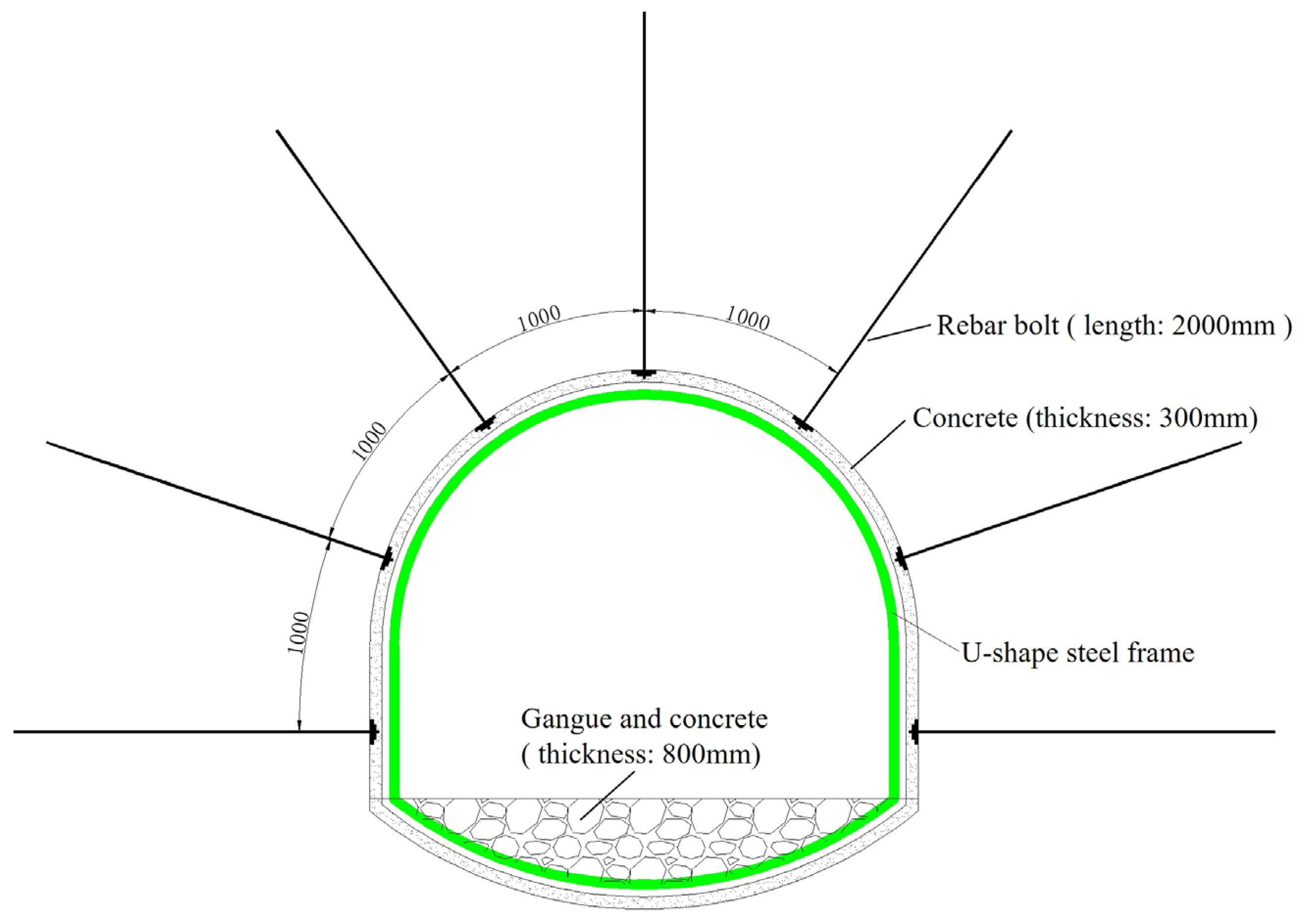
- Failure of the support materials. The concrete layer fell off. The U-shaped steel frames were twisted or destroyed (Figure 4c,d) and were, thus, unable to support the roadway. The support materials utilized were clearly unsuitable for resisting the deformation of the swelling soft rock roadway.
3.2. Type of Large-Deformation Failure Mechanism
- (1)
- Type I is termed a physicochemical expansion type, which is related to the chemical properties of the molecular structure of the soft rock. A significant portion of the mineral composition of the surrounding rocks consists of clay minerals, particularly smectite (79%) and kaolinite (78%). The rock sample also appears to have strong expansibility (Table 2). Therefore, the deformation mechanism in type I can be named type IAB.
- (2)
- Type II is termed a stress expansion type, which is associated with the force source. Tectonic stress in the near horizontal direction and gravitational stress in the vertical direction are the main stresses that act on this roadway. The roadway is in very close proximity to other roadways, generating previous engineering deviatoric stress. Therefore, the deformation mechanism in type II can be named type IIABD.
- (3)
- Type III is termed a structural deformation type, which is related to the combination characteristics of the chamber structure and the rock mass structural plane. The surrounding rock has six faults, a weak intercalated layer, and obvious bedding. The deformation mechanism in type III can be named type IIIABC.
3.3. Transformation of Nonlinear Large-Deformation Mechanism
- (1)
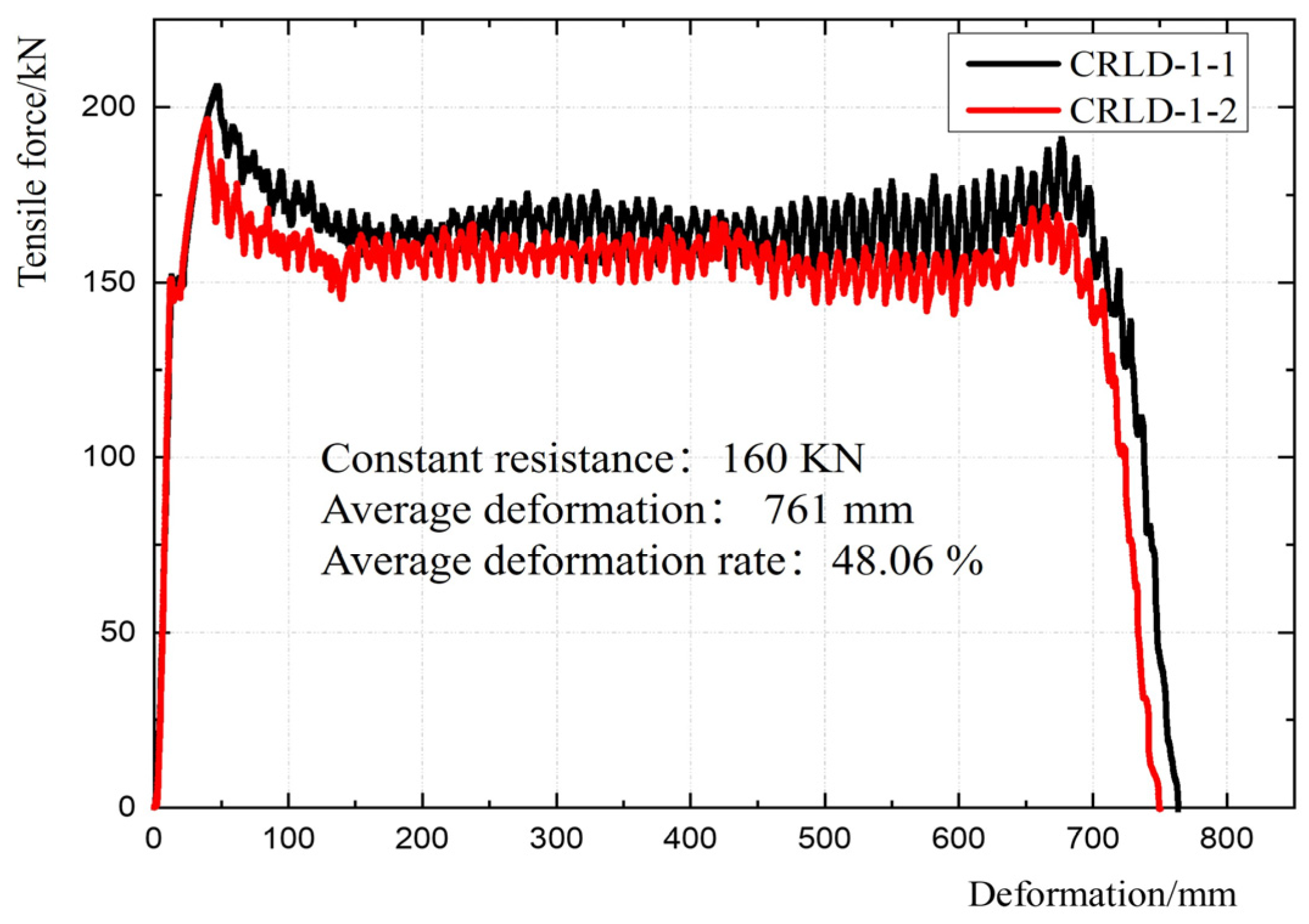
- First step: The CRLD bolts make full use of the constant resistance and large deformation by absorbing the energy released by surrounding rocks through deformation. Thus, the composite mechanism of type IABIIABDIIIABC can be converted to type IIABDIIIABC.
- (2)
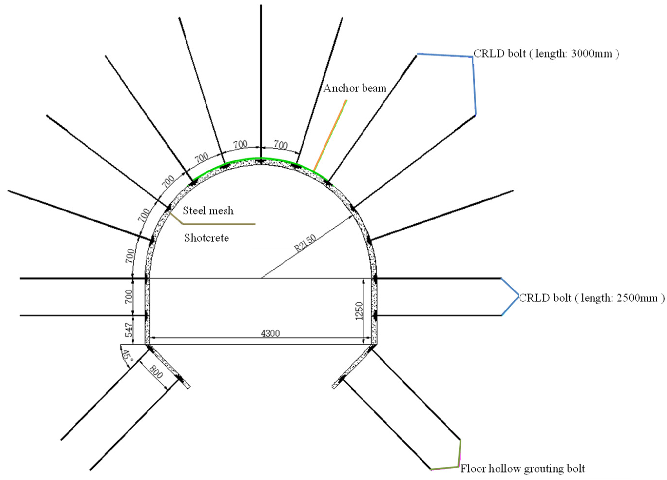
- Second step: The combined application of 3000 and 2500 mm long CRLD bolts provides effective control of large deformations, and floor grouting bolts are adopted to enhance the floor support strength. Through these methods, type IIABDIIIABC can be transformed to type IIABD.
- (3)
- Third step: The combined use of rock bolts, steel mesh, and anchor beams can improve the support strength. Floor grouting bolts can enhance the strength of the floor. The coupling control methods can play an important role in converting the complex mechanism to a simple type IIB.
4. Results
4.1. Support Mechanism of CRLD Bolt
- (1)
- Stage 1: In this stage, the supporting force of the bolt is less than the design resistance value of the CRLD bolt. In the process, the CRLD bolt plays the same supporting role as an ordinary bolt and plays the function of resisting the deformation of the surrounding rock.
- (2)
- Stage 2: In this stage, the CRLD bolt generates deformation, depending on its own constant-resistance device, and the deformation of supporting materials can absorb the energy released by the surrounding rock in the deformation process, making the surrounding rock of the roadway develop into new support in a balanced way.
- (3)
- Stage 3: In this stage, the deformation energy of the surrounding rock gradually decreases after the deformation of the surrounding rock. Under the support of CRLD bolts, the surrounding rock of the roadway reaches a new equilibrium and stable state again.
4.2. Stability Control and Application
- (1)
- Bolt: Two sizes of CRLD bolts were used—one with a length of 3000 mm and the other with a length of 2500 mm. These CRLD bolts were aligned in parallel, with a space of 700 × 700 mm between them.
- (2)
- Anchor beam: U-shaped steel beams were adopted, each with a length of 3000 mm. They were processed into an arc shape to match the section geometry of the roadway. Each anchor beam was fastened with four 3000 mm long CRLD bolts. The bolt holes on the beam were processed into an oval shape.
- (3)
- Floor grouting bolt: Two 3000 mm long hollow floor grouting bolts were placed in each corner of the floor. The bolts were aligned in parallel, and the space between the rows of each bolt was 800 × 700 mm.
- (4)
- Steel mesh: The diameter of the steel mesh is 8.0 mm. Each piece has a conventional size of 800 × 2200 mm, which consists of many small squares with a size of 100 × 100 mm. The overlapped portion of the connection part is 100 mm.
- (5)
- Concrete: Steel fiber concrete with a strength of C20 was used.
4.3. Support Effect of the New Support Countermeasure
- (1)
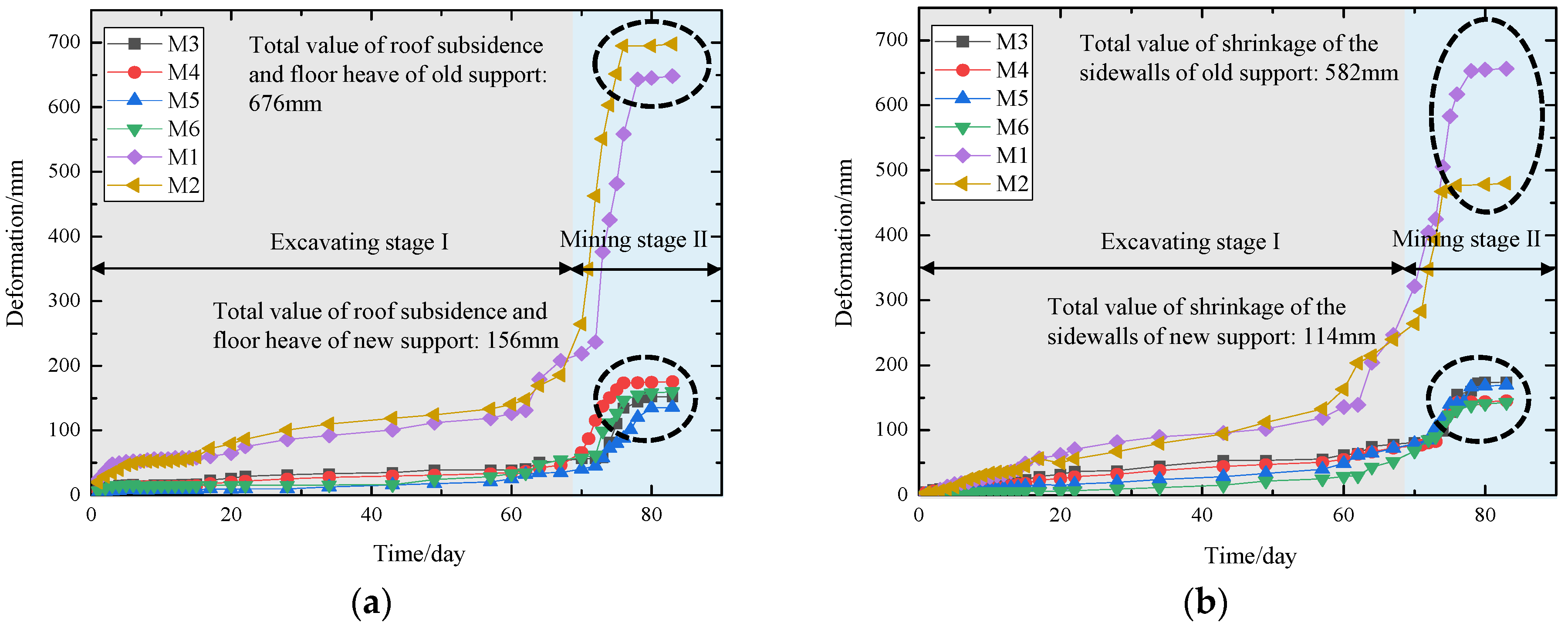
- In excavating stage I, the deformation situation had three stages: the active stage, transitional stage, and stable stage. After the fast deformation of the I1 and I2 stages, the total deformation of the surrounding rock appeared stable, which was the stable stage of I3.
- (2)
- In mining stage II, the deformation situation of the surrounding rock also had three stages under the impact of the mining of the working face. In the first stage, II1, the deformation rate was slow, and the deformation value was small. In the second stage, II2, the deformation rate became faster. The total deformation value became larger than that in stage II1. The deformation was the greatest. In stable stage II3, the deformation rate was zero, and the total deformation was a stable value. It is clear that the amount of the deformation of this stage is much greater than that of excavating stage I, and the lasting time of this stage is much less than that of excavating stage I.
- (1)
- New support: In the excavating stage, the average value of the roof subsidence and floor heave was 23 mm, and the average shrinkage of the sidewalls was 30 mm. The time it takes to enter the stable stage of I3 is about 6 days. In the mining stage, the total value of the roof subsidence and floor heave was 156 mm, and the total deformation of the shrinkage of the sidewalls was 114 mm. The time it takes to enter the stable stage of II3 is about 10 days.
- (2)
- Old support: In the excavating stage, the average value of the roof subsidence and floor heave was 101 mm, and the average shrinkage of the sidewalls was 85 mm. The time it takes to enter the stable stage of I3 is about 12 days. In the mining stage, the total value of the roof subsidence and floor heave was 676 mm, and the total deformation of the shrinkage of the sidewalls was 582 mm. The time it takes to enter the stable stage of II3 is about 18 days.
5. Conclusions
- (1)
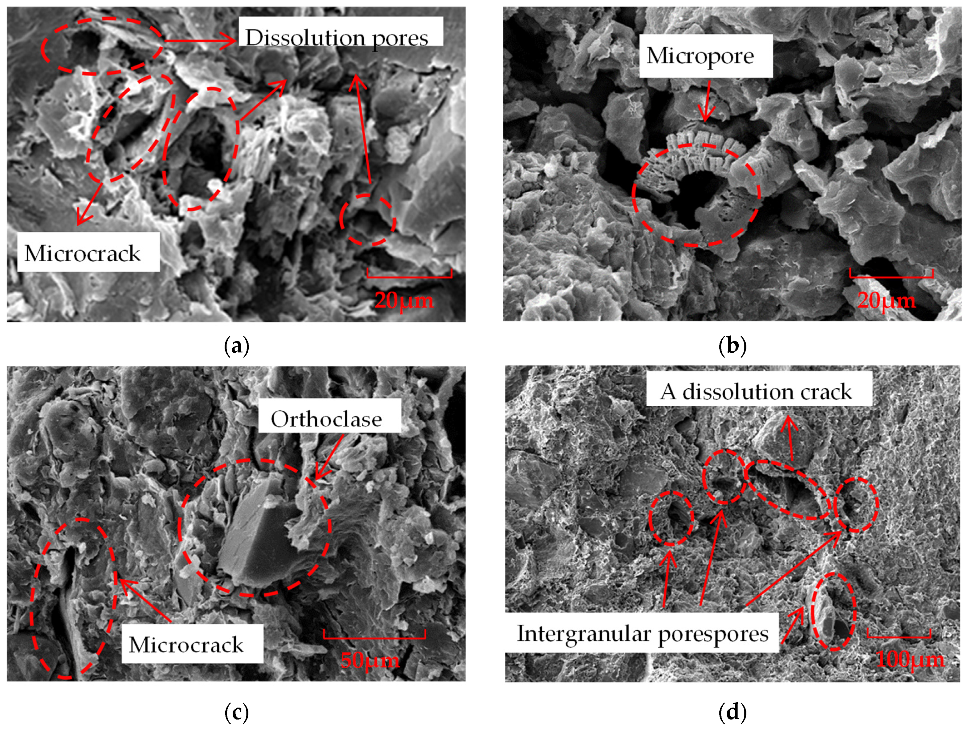
- On the basis of the X-ray diffraction and electron microscope scanning results, the characteristics of the swelling soft rock can be derived: ① The swelling soft rock had a large proportion of clay minerals, especially smectite and kaolinite; ② massive dissolution holes were found on the surface of the minerals, and part of them were padded with argillaceous components; and ③ the development of microfractures in the rocks is fine, and some of them are well connected, with a portion of them filled with albite, pyrite, and halite.
- (2)
- An on-site investigation derived the following characteristics of large deformation: ① large deformation and overall shrinkage of the roadway; ② persistent deformation; and ③ failure of support materials.
- (3)
- The compound deformation mechanism can be transformed into a simple one through some countermeasures. The design of coupling support that contains an anchor beam, steel mesh, CRLD bolts, floor grouting bolts, and steel fiber concrete was proposed and applied.
- (4)
- By releasing the stresses accumulated by the swelling soft rock, the CRLD bolts control the deformation of the roof and sidewalls effectively. The floor grouting bolt effectively controls the ground uplift by cutting off the slip line of the basement angle.
- (5)
- The average total deformation of the roadway surface in the new support is only about 21.4% of that in the old support. The total time of the support materials entering the stable stages of I3 and II3 in the new support is nearly 53.3% of that in the old support. The proposed coupling stability control method can effectively control the nonlinear large deformation of the swelling soft rock. This approach can be taken as a good reference for the nonlinear large-deformation mechanism and stability control of swelling soft rock roadways in sea areas.
Author Contributions
Funding
Institutional Review Board Statement
Informed Consent Statement
Data Availability Statement
Conflicts of Interest
References
- BP p.l.c. BP Statistical Review of World Energy 2022; BP p.l.c.: London, UK, 2022. [Google Scholar]
- China National Bureau of Statistics. Statistical Bulletin on National Economic and Social Development 2022; China National Bureau of Statistics: Beijing, China, 2022.
- Development Strategy and Planning Division of the National Development and Reform Commission. The Outline of the 14th Five-Year Plan for National Economic and Social Development and Vision 2035 of the State and All Regions; People’s Press: Beijing, China, 2022. [Google Scholar]
- Institute of Resources and Environmental Policy of Development Research Center of The State Council. Progress Report on China’s Energy Revolution; Petroleum Industry Press: Beijing, China, 2022. [Google Scholar]
- Miao, X.; Liu, W.; Chen, Z. Seepage Theory of Mining Rock Mass; Science Press: Beijing, China, 2004. [Google Scholar]
- Wu, X.; Yu, Q.; Wang, X.; Duan, Q.; Li, X.; Yang, J.; Bao, Y. Exploitation of coal resources under surface water body. Chin. J. Rock Mech. Eng. 2006, 25, 1029–1036. [Google Scholar]
- Feng, F.; Chen, S.; Wang, Y.; Huang, W.; Han, Z. Cracking mechanism and strength criteria evaluation of granite affected by intermediate principal stresses subjected to unloading stress state. Int. J. Rock Mech. Min. Sci. 2021, 143, 10473. [Google Scholar] [CrossRef]
- Chen, S.; Feng, F.; Wang, Y.; Li, D.; Jiang, N. Tunnel failure in hard rock with multiple weak planes due to excavation unloading of in-situ stress. J. Cent. South Univ. 2020, 27, 2864–2882. [Google Scholar] [CrossRef]
- Feng, F.; Xie, Z.; Xue, T.; Wang, E.; Huang, R.; Li, X. Application of a combined FEM/DEM approach for teaching a deep rock mass mechanics course. Sustainability 2023, 15, 937. [Google Scholar] [CrossRef]
- Xie, H.; Gao, F.; Ju, Y. Research and Development of Rock Mechanics in Deep Ground Engineering. Chin. J. Rock Mech. Eng. 2015, 34, 2161–2178. [Google Scholar]
- He, M.; Xie, H.; Peng, S.; Jiang, Y. Study on Rock Mechanics in Deep Mining Engineering. Chin. J. Rock Mech. Eng. 2015, 24, 2803–2813. [Google Scholar]
- Xie, H. Research Framework and Anticipated Results of Deep Rock Mechanics and Mining Theory. Adv. Eng. Sci. 2017, 49, 1–16. [Google Scholar]
- Yuan, L. Strategic Thinking of Simultaneous Exploitation of Coal and Gas in Deep Mining. J. China Coal Soc. 2016, 41, 1–16. [Google Scholar]
- Kang, H. Support Technologies for Deep and Complex Roadways in Underground Coal mines: A Review. Int. J. Coal Sci. Tech. 2014, 1, 261–277. [Google Scholar] [CrossRef]
- He, M. Progress and challenges of soft rock engineering in depth. J. China Coal Soc. 2014, 39, 1409–1417. [Google Scholar]
- He, M.; Gong, W.; Wang, J.; Qi, P.; Tao, Z.; Du, S.; Peng, Y. Development of a novel energy-absorbing bolt with extraordinarily large elongation and constant resistance. Int. J. Rock Mech. Min. Sci. 2014, 67, 29–42. [Google Scholar] [CrossRef]
- Sun, X.; Zhang, Y.; Wang, D.; Yang, J.; Xu, H.; He, M. Mechanical properties and supporting effect of CRLD bolts under static pull test conditions. Int. J. Rock Mech. Min. Sci. 2017, 24, 1–9. [Google Scholar] [CrossRef]
- Sun, X.; Wang, D.; Wang, C.; Liu, X.; Zhang, B.; Liu, Z. Tensile properties and application of constant resistance and large deformation bolts. Chin. J. Rock Mech. Eng. 2014, 33, 1765–1771. [Google Scholar]
- Wang, D.; Jiang, Y.; Sun, X.; Luan, H.; Zhang, H. Nonlinear Large Deformation Mechanism and Stability Control of Deep Soft Rock Roadway: A Case Study in China. Sustainability 2019, 11, 6243. [Google Scholar] [CrossRef]
- Yang, X.; Pang, J.; Liu, D. Deformation mechanism of roadways in deep soft rock at Hegang Xing’an coal Mine. Int. J. Min. Sci. Tech. 2013, 23, 307–312. [Google Scholar] [CrossRef]
- He, M.; Gao, Y.; Yang, J.; Gong, W. An Innovative Approach for Gob-Side Entry Retaining in Thick Coal Seam Longwall Mining. Energies 2017, 10, 1785. [Google Scholar] [CrossRef]
- He, M.; Jing, H.; Sun, X. Soft Rock Engineering Mechanics; Science Press: Beijing, China, 2002. [Google Scholar]
- He, M.; Sun, X. Support Design and Construction Guide of Soft Rock Roadway Engineering in Chinese Coal Mines; Science Press: Beijing, China, 2004. [Google Scholar]
- He, M. Conception system and evaluation indexes for deep engineering. Chin. J. Rock Mech. Eng. 2005, 24, 2853–2858. [Google Scholar]
- Zhang, N.; Liu, L.; Hou, D.; He, M.; Liu, Y. Geomechanical and water vapor absorption characteristics of clay-bearing soft rocks at great depth. Int. J. Min. Sci. Tech. 2014, 24, 811–818. [Google Scholar] [CrossRef]
- Guo, Z.; Wang, H.; Ma, Z.; Wang, P.; Kuai, X.; Zhang, X. Research on the Transmission of Stresses by Roof Cutting near Gob Rocks. Energies 2021, 14, 1237. [Google Scholar] [CrossRef]
- Ma, Z.; Wang, Y.; Huang, L.; Wang, H.; Wang, J.; Wang, Z.; Wang, Y.; Wang, B. Research on the Stability Mechanism of the Surrounding Rock of Gob-Side Entry Retaining by Roof Cutting in Dianping Coal Mine. Minerals 2022, 12, 965. [Google Scholar] [CrossRef]
- Guo, H.; Li, B.; Zhang, Y.; Wang, X.; Zhang, F. Hydrophilic characteristics of soft rock in deep mines. Int. J. Min. Sci. Technol. 2015, 25, 177–183. [Google Scholar] [CrossRef]
- Yang, X.; Wang, J.; Zhu, C.; He, M.; Gao, Y. Effect of wetting and drying cycles on microstructure of rock based on SEM. Environ. Earth Sci. 2019, 78, 1–10. [Google Scholar] [CrossRef]
- Guo, H.; Zhao, J.; Liu, P. Experimental studies and chemical analysis of water on weakening behaviors of deep soft rock. Chin. J. Rock Mech. Eng. 2018, 37, 3374–3381. [Google Scholar]
- He, M.; Yang, X.; Sun, X. Study on Clay Mineral Characteristics for Soft Rock of Coal Mine in China; China Coal Industry Publishing House: Beijing, China, 2006. [Google Scholar]
- Sun, X.; He, M.; Yang, X. Research on nonlinear mechanics design method of bolt-net-anchor coupling support for deep soft rock tunnel. Rock Soil Mech. 2006, 27, 1061–1065. [Google Scholar]



| Lithology | Thickness/m | Geological Description |
|---|---|---|
| Oil shale | 3.38 | Brown grey, oil content is high in the upper part |
| Oily mudstone | 15.87 | Compact rock formation, blocky structure, upper horizontal bedding, lower bedding developed, locally containing soft clay interlayer |
| Coal-2 | 4.45 | Brown black, notably bright coal, followed by dull coal |
| Sand–mudstone | 12.40 | Mudstone or fine sandstone with blocky structure, loose mudstone easily swells when exposed to water |
| Location | Lithology | Compressive Strength | Water Absorption | Swelling Rate |
|---|---|---|---|---|
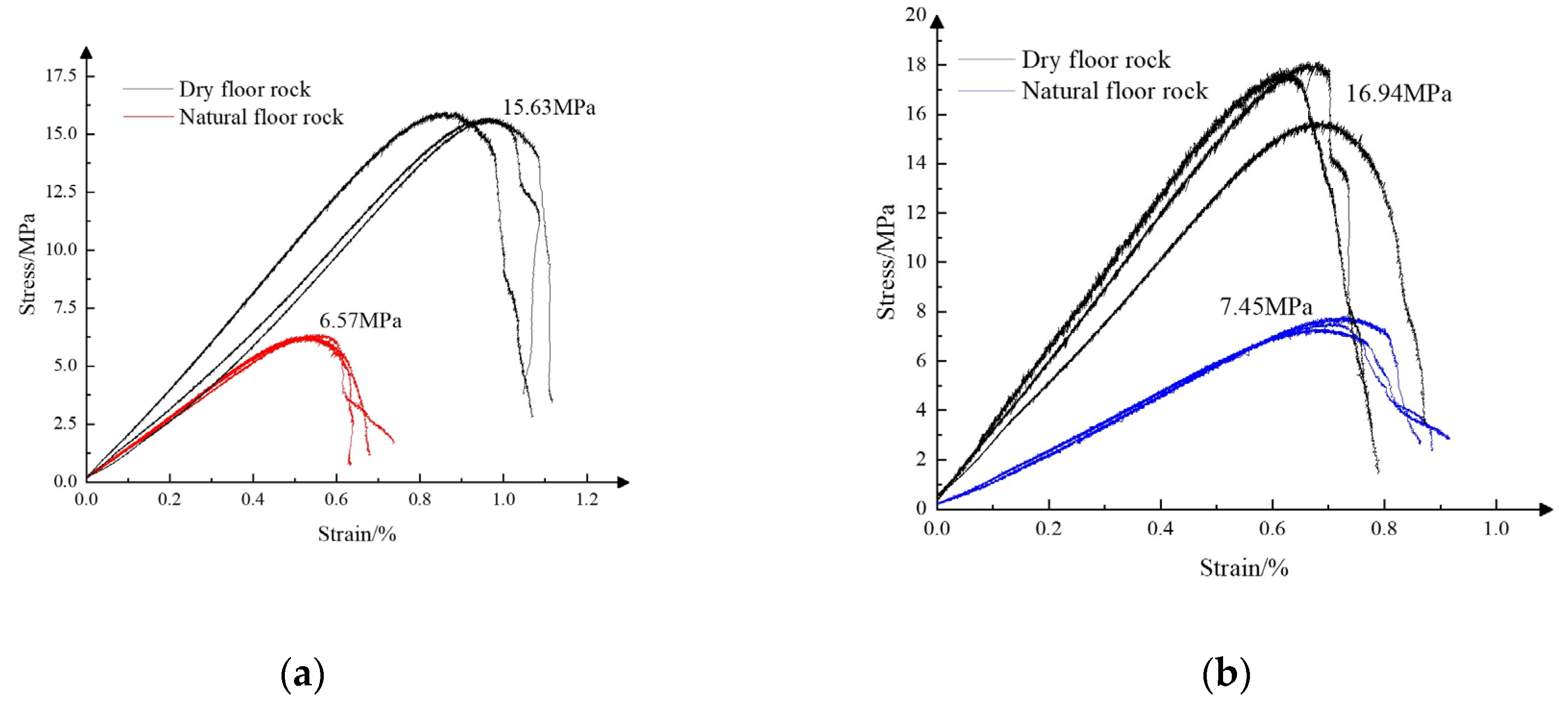
| Roof | Oily mudstone | 6.57 MPa | 42.60% | 15.10% |
| Floor | Sand–mudstone | 7.45 MPa | 64.21% | 21.50% |
| Location | Lithology | Species and Content (%) of Mineral | Total Clay Mineral Content (%) | ||||
|---|---|---|---|---|---|---|---|
| Quartz | Orthoclase | Albite | Pyrite | Halite | |||
| Roof | Oily mudstone | 16.0 | / | 8.5 | 0.7 | 1.4 | 73.4 |
| Floor | Sand–mudstone | 53.7 | 22.3 | 9.0 | / | / | 15.0 |
| Location | Lithology | Relative Contents of the Clay Minerals (%) | Mixture Layer Ratio (S, %) | ||||||
|---|---|---|---|---|---|---|---|---|---|
| S | I/S | I | K | C | C/S | I/S | C/S | ||
| Roof | Oily mudstone | 79 | / | 4 | 17 | / | / | / | / |
| Floor | Sand–mudstone | / | 19 | 3 | 78 | / | / | 40 | / |
Disclaimer/Publisher’s Note: The statements, opinions and data contained in all publications are solely those of the individual author(s) and contributor(s) and not of MDPI and/or the editor(s). MDPI and/or the editor(s) disclaim responsibility for any injury to people or property resulting from any ideas, methods, instructions or products referred to in the content. |
© 2023 by the authors. Licensee MDPI, Basel, Switzerland. This article is an open access article distributed under the terms and conditions of the Creative Commons Attribution (CC BY) license (https://creativecommons.org/licenses/by/4.0/).
Share and Cite
Dong, L.; Wang, D.; Sun, X.; Jiang, Y.; Luan, H.; Xu, H.; Li, B.; Cai, F. Large-Deformation Failure Mechanism and Stability Control of a Swelling Soft Rock Roadway in a Sea Area: A Case Study in Eastern China. Sustainability 2023, 15, 5323. https://doi.org/10.3390/su15065323
Dong L, Wang D, Sun X, Jiang Y, Luan H, Xu H, Li B, Cai F. Large-Deformation Failure Mechanism and Stability Control of a Swelling Soft Rock Roadway in a Sea Area: A Case Study in Eastern China. Sustainability. 2023; 15(6):5323. https://doi.org/10.3390/su15065323
Chicago/Turabian StyleDong, Ling, Dong Wang, Xiaoming Sun, Yujing Jiang, Hengjie Luan, Huichen Xu, Baocheng Li, and Feng Cai. 2023. "Large-Deformation Failure Mechanism and Stability Control of a Swelling Soft Rock Roadway in a Sea Area: A Case Study in Eastern China" Sustainability 15, no. 6: 5323. https://doi.org/10.3390/su15065323
APA StyleDong, L., Wang, D., Sun, X., Jiang, Y., Luan, H., Xu, H., Li, B., & Cai, F. (2023). Large-Deformation Failure Mechanism and Stability Control of a Swelling Soft Rock Roadway in a Sea Area: A Case Study in Eastern China. Sustainability, 15(6), 5323. https://doi.org/10.3390/su15065323


