Article

Three-Dimensional Analysis of Load Transfer Mechanism for Deep Cement Mixing Piled Embankment under Static and Cyclic Load

1
College of Transportation Engineering, Nanjing Tech University, Nanjing 211816, China
2
Key Laboratory of Ministry of Education for Geomechanics and Embankment Engineering, Hohai University, Nanjing 210098, China
3
Guangxi Key Laboratory of Disaster Prevention and Engineering Safety, Guangxi University, Nanning 530004, China
4
Key Laboratory of Disaster Prevention and Structural Safety of Ministry of Education, Guangxi University, Nanning 530004, China
5
College of Civil Engineering and Architecture, Guangxi University, Nanning 530004, China
*
Author to whom correspondence should be addressed.
Sustainability 2023, 15(8), 6532; https://doi.org/10.3390/su15086532
Submission received: 25 February 2023 / Revised: 3 April 2023 / Accepted: 7 April 2023 / Published: 12 April 2023

Abstract

:
Piles have been widely used to improve the bearing capacity of the soft foundation. The existing research obtains significant findings on the load transfer mechanism for rigid piled embankments. However, limited studies have been focused on the deep cement mixing (DCM) piled embankment. To grasp the load transfer characteristics of DCM piled embankments, a three-dimensional numerical simulation was conducted in this study, which was validated by the measurements from the field case. It was found that the effect of soil arching was reduced compared with the rigid piled embankment. This induced approximately 61.5% larger vertical stress transferred to the subsoil surface and approximately 83–150% larger settlement of the embankment in DCM piled foundation system. To further understand the working mechanism of this system, the factors which influence the load transfer mechanism were investigated. It is found that the area replacement ratio is the most influential factor affecting the settlement at the top of the embankment, whereas the elastic modulus of the DCM pile influences most the vertical stress and the earth pressure coefficient. The cyclic load with vehicle speeds of 90 km/h will lead to approximately 34% growth of embankment settlement and about 11% reduction in the maximum earth pressure coefficient. Based on the numerical simulation results, the analytical equation of the normalized vertical stress acting on the subsoil surface for the DCM piled foundation was proposed and validated by two field cases, with the difference in the range of 13.8~16.7%.

1. Introduction

Civil engineers have experienced many challenges (e.g., large settlements and instability problems) when roads, highway and high-speed railway supported by embankments are built over soft soils. To overcome these potential problems, a great deal of ground improvement technologies have been developed, such as deep cement mixing (DCM) piled embankment. Due to its virtues of construction efficiency and economic benefits, DCM piles have been increasingly used to improve the bearing capacity and reduce the settlement of the soft foundation. The existing case studies showed that DCM piles were widely applied in many projects, such as the Pacific highway in Australia and the Beijing–Shanghai high-speed railway in China (Yapage [1], Zhuang and Wang [2]).
DCM piles are normally installed through soft soil layers to transfer the overburden (e.g., embankment weight and traffic loads) to firm stratum (Han [3], Liu [4]). Square or triangular grid patterns of a single pile are usually arranged with area replacement ratios of 0.1~0.5 (Terashi [5], Jamsawang [6]). Compared with the rigid pile (e.g., CFG pile), the elastic modulus of the DCM pile is significantly smaller, with the value in the range of 30~880 MPa (Jamsawang [6], Voottipruex [7], Jiang [8], Jamsawang [9]). The length of the DCM piles is in the range of 7.0~16.5 m (Liu [4], Jamsawang [6], Voottipruex [7]). In recent years, the deep cement mixing pile with T-shaped formation has been popular, applied for its higher bearing capacity (Yi [10], Phutthananon [11], Phutthananon [12]).
A series of studies have been conducted on the load transfer mechanism and the settlement characteristics of the piled embankment system, including analytical solutions (e.g., Hewlett and Randolph [13], Zhang [14], Van Eekelen [15], Zhuang [16], Nguyen [17]), numerical simulations (e.g., Indraratna [18], Liu and Rowe [19], Wang [20]) and field investigations (e.g., Liu [21], Nunez [22], Zhao [23]). Furthermore, the dynamic response of the piled embankment system under highway and high-speed train load have been investigated over recent years (e.g., Zhuang [24], Chango [25], Chen [26]). In those publications, soil arching was found to be a key factor of the load transfer in piled embankments. The most studied parameters of the load transfer include the embankment height, cohesion and friction angle of the embankment, spacing and length of the pile, and soil stiffness, as well as—depending on the selected failure model (e.g., Vipulanandan [27])—material properties (e.g., Isleem [28], Vipulanandan [29]), since it describes different mechanical behaviors, etc. However, these studies are mostly concerned with the rigid pile composite foundation (e.g., CFG piled foundation). Limited studies have been conducted on the load transfer mechanism of DCM piled foundation (e.g., development of the soil arching).
The goal of this paper is to investigate the load transfer mechanism of DCM piled foundations according to the flow chart for the work process as shown in Figure 1. Firstly, a field case study of a highway located in Thailand is introduced to establish the numerical model for DCM piled foundations. The numerical model is validated by the measurements in this field case study. Secondly, based on the numerical model, the comparison analysis between the rigid piled (CFG pile) foundation and DCM piled foundation was carried out related to the vertical stress, the earth pressure coefficient, and the displacement along a vertical profile of the embankment. To further understand the soil arching in the DCM piled foundation, the parametric studies were conducted including the elastic modulus of DCM piles, the length of DCM piles, the area replacement ratio, as well as the embankment height. In addition, the response of DCM piled foundation reinforced by geogrid subjected to the cyclic load was also analyzed. Thirdly, the equation to calculate the normalized vertical stress acting on the subsoil surface of DCM piled foundation is proposed and validated by the measurements of two field cases. The research in this study has important theoretical and engineering significance for the development of the soil arching effect under static and traffic loads. The findings will provide guidance for the settlement control of soft soils for urban road transportation infrastructure (e.g., highway and high-speed railway).

2. Selected Case Study

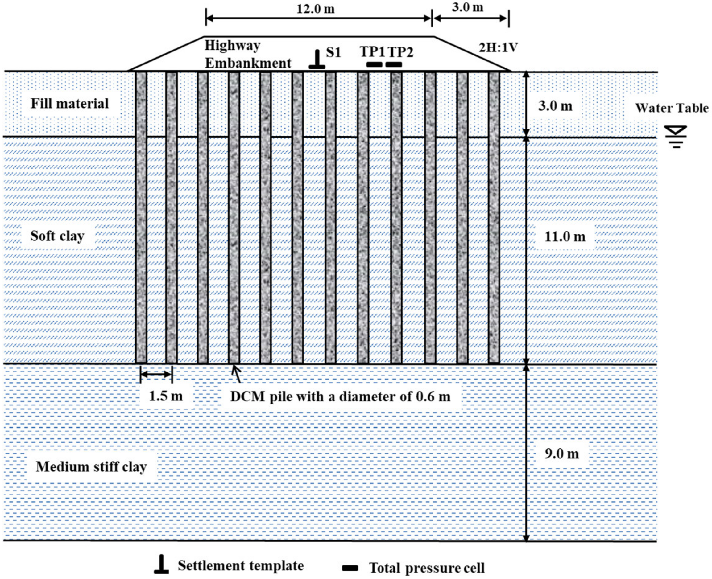
2.1. General Project Information

In this work, we consider a full-scale embankment of Station KM 6+055 of a highway which is located in the Bangbo district of Samutprakan province, Thailand. The embankment is 1.5 m high and its crest width is 12.0 m. The side slope of the embankment is 1.0 V to 2.0 H. The soft soil, having a thickness of 23.0 m, is underlain by stiff clay. To improve the bearing capacity of the soft ground, DCM piles was adopted in this site project, and no geosynthetic reinforcement was used to strengthen the embankment. Here we just provide some necessary information to describe the numerical simulation; one can find further detailed description of its construction, ground conditions, instruments and measurement results in the work of Jamsawang [6].

2.2. Site Conditions and Instruments

Figure 2 shows the cross section of the studied embankment. It is clear that the soil profile is a fill material with 3 m thickness underlain by soft clay with 11 m thickness, a 9 m thick medium-stiff clay, and stiff clay, respectively. The DCM piles were installed under the highway embankment, distributed in a square pattern with an interval space of 1.5 m. The pile tips of the DCM piles were located on the medium-stiff clay layer. Table 1 and Table 2 summarize the parameters of the embankment, DCM piles and the layered subsoil given by Jamsawang [6].
As described in Figure 2, the earth pressure cells were placed on the top of the pile caps and on the centerline between DCM piles at the surface of subsoil. The settlement plates were also installed at the centerline between DCM piles. The monitoring began from the embankment construction period and lasted for about 240 days after it was completed. In order to validate the results derived from the numerical simulation, the vertical stress acting on the surface of the subsoil, and the settlement at the surface of the subsoil measured in the field case are presented and discussed in the following sections.

3. Numerical Modeling

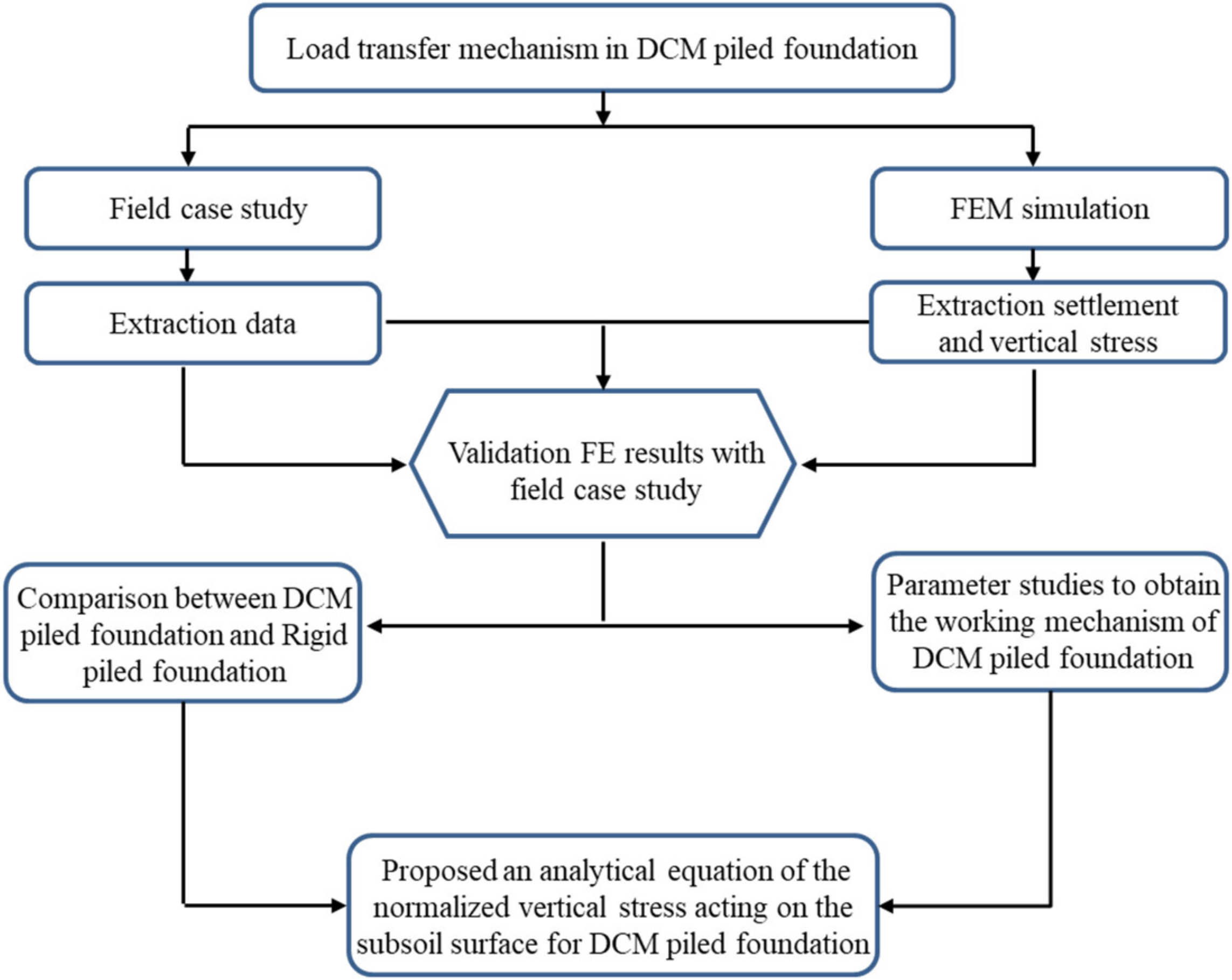
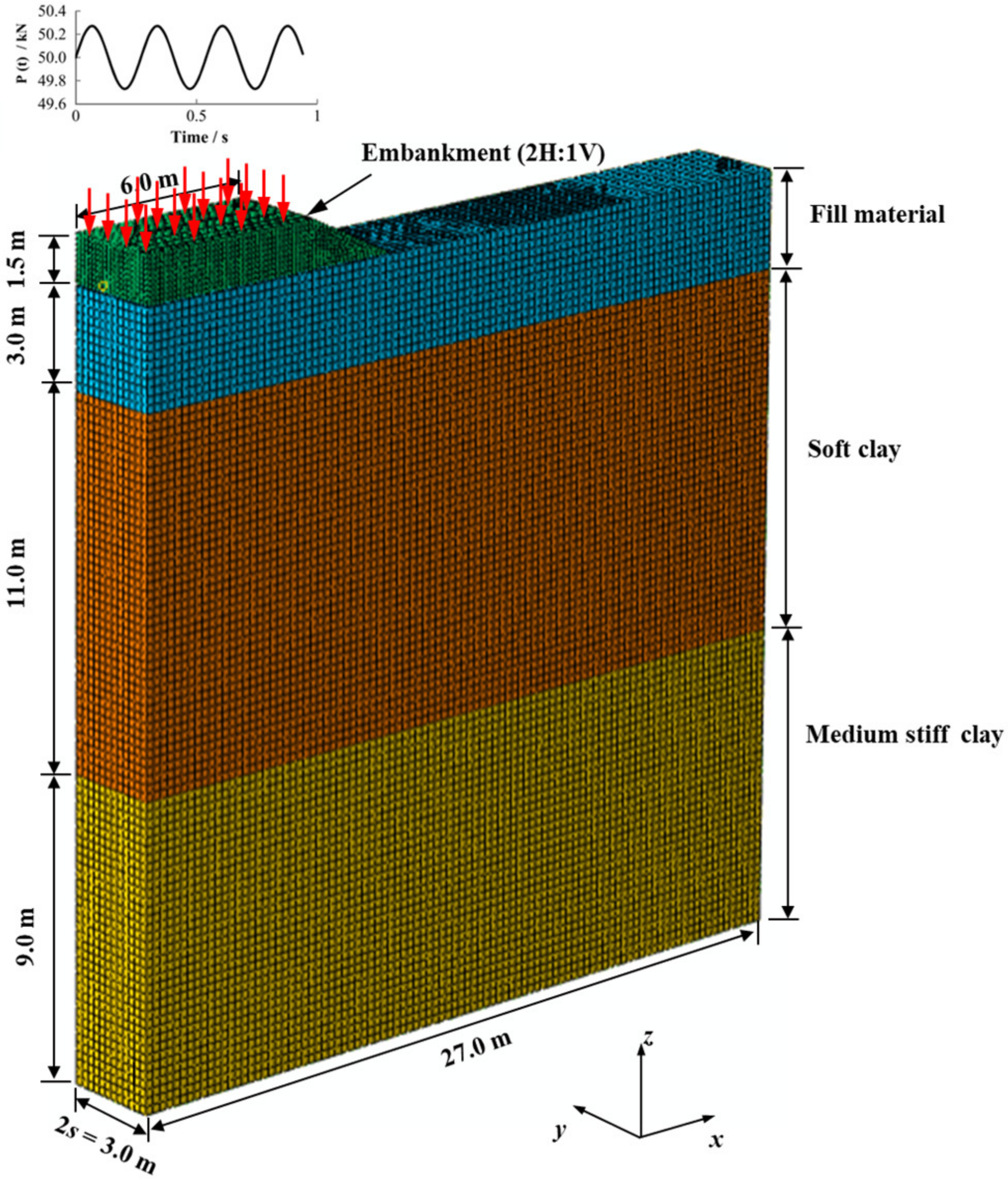
3.1. Introduction to the Numerical Model and the Calculation Method

Based on the aforementioned field case, the commercial FEM package ‘ABAQUS’ was adopted for the whole numerical simulations. Figure 3 displayed the 3D numerical geometrical model of the studied DCM pile-supported embankment. For simplicity, only half of the embankment structure was considered for the FEM simulations, since the embankment was symmetrical along its centerline. The depth of the foundation soil was set to 23.0 m, overlying a stiff clay stratum. To minimize its boundary effect, the length of lateral model boundary is three times the half width of embankment base, namely 27.0 m horizontally, as shown in Figure 3. In this model, we present a section 3.0 m wide, and two rows of piles are configured beneath the embankment for numerical analysis.
The mechanical behavior of the embankment fill was described by perfectly elasto-plastic constitutive relation with the Mohr–Coulomb failure criterion. As for the pile and the geogrid reinforcement, it was assumed to exhibit linear elastic behavior. Then the constitutive model of two layers of soft clay and medium-stiff clay was characterized by a modified cam clay (MCC) model. The material parameters for each part are listed in Table 1 and Table 2. One should note that the compressibility is characterized by two parameters in the MCC model, namely, the modified compression index λ and modified swelling index κ. These two parameters can be calibrated by the one-dimensional consolidation test.

3.2. Boundary Conditions and Applied Load

As for the boundary condition, the displacement is set to zero in the x, y and z direction at the base of the numerical model (z = 0 plane), with no displacements in the direction perpendicular to the symmetry plane (x = 0 plane) and to the far field lateral boundary (x = 27 plane). In addition, two vertical planes in the y-direction (y = 0 and y = 3 planes) were set to zero displacement due to the symmetrical condition being considered. As for the drainage boundary condition, the water table was at a depth of 3.0 m below ground level. A zero-pore-pressure boundary condition was applied at the level of the water table (z = 20). The base of the model is regarded as impermeable due to the existence of low-permeability stiff clay, and a lateral flow is not permitted across the vertical planes of x = 0, x = 27, y = 0, y = 3.
For the applied load, the embankment was built after the boundary condition and initial stress, together with pore pressure conditions, were all applied to the numerical model. Followed by the construction step of the embankment, a consolidation stage was performed until the excess pore water pressure approached zero. The moving vehicle loads considered in the parametric studies in the following section were evoked after the consolidation step was completed. This vehicle loads were applied onto the top of the embankment by the subroutine DLOAD. In this analysis, the periodically repeated moving vehicle loads were modeled using a simple sine curve as described in Zhang and Liang [30] for 100 load cycles.

3.3. Finite-Element Mesh Details

For the embankment, DCM piles, and surrounding soils, to withstand the effect of the underground water table, eight-node stress-pore pressure coupled brick elements (C3D8P) were used under the water table. Thus, the coupled mechanical and hydraulic behavior could be considered. Then the ones above the water table, the eight-noded quadratic brick elements with reduced integration and without pore pressure degrees of freedom (C3D8R), were adopted. For the geogrid reinforcement, the four-noded quadrilateral membrane elements with reduced integration (M3D4R) were used in this study. It was assumed that the interface friction angle between the geogrid and the embankment was equal to that of the embankment, which was also used in Liu [21], while the interface friction angle between the DCM piles and the surrounding soils was determined as 0.7 times that of soft soils, according to the demonstration by Potyondy [31] for the clay.

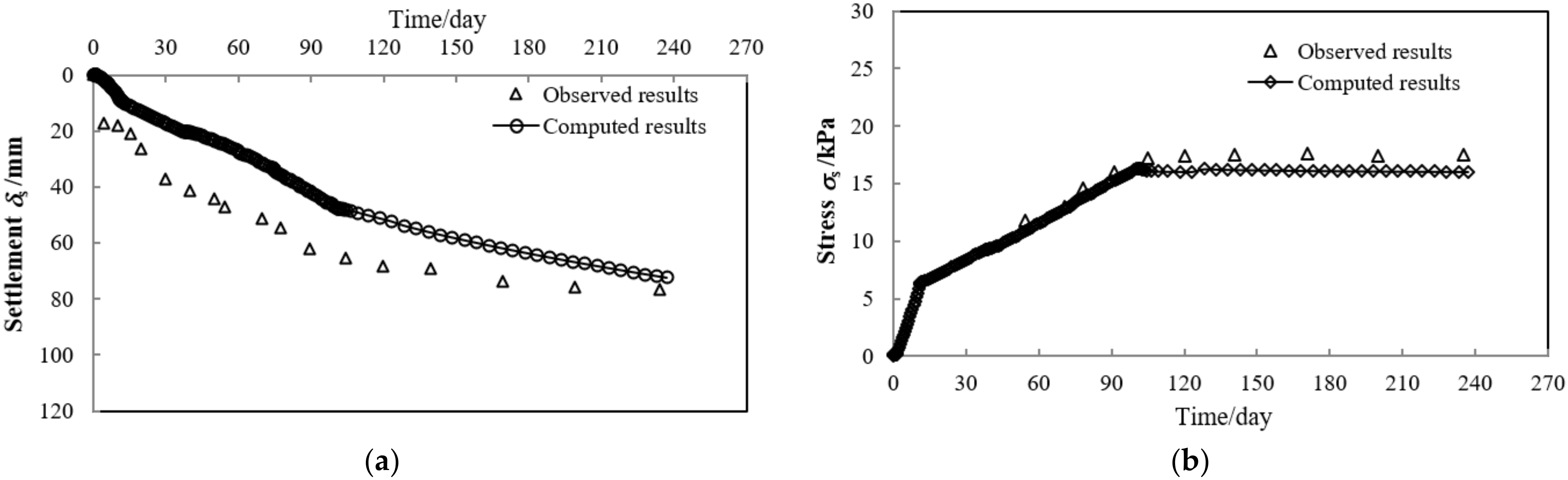
3.4. Verification and Validation of the Numerical Model

Figure 4a,b, respectively, present a comparison of the field measured and simulated settlement at the surface of the subsoil δs and the vertical stress at the centerline of the subsoil σs. In Figure 4a, the measured and computed settlement over 240 days at the base of the embankment is presented. It was found that the computed results appear to be consistent with the general trend of the field measured data. The observed surface settlement δs reached 77 mm after 240 days of construction, while the simulated settlement results were approximately 72 mm. It can be calculated that the numerical surface settlements δs slightly underestimated the measured values by 6%. Figure 4b displays the pressures acting on the soil surface between the DCM piles σs. The trend of the pressures acting on the subsoil versus time were reasonably captured, the numerical magnitudes generally match well with observed data, and the maximum difference is approximately 8%. It is found that the computed results agree reasonably well with the measurements considering both settlement and the vertical stress at the surface of the subsoil, which validates the correctness of the numerical model.

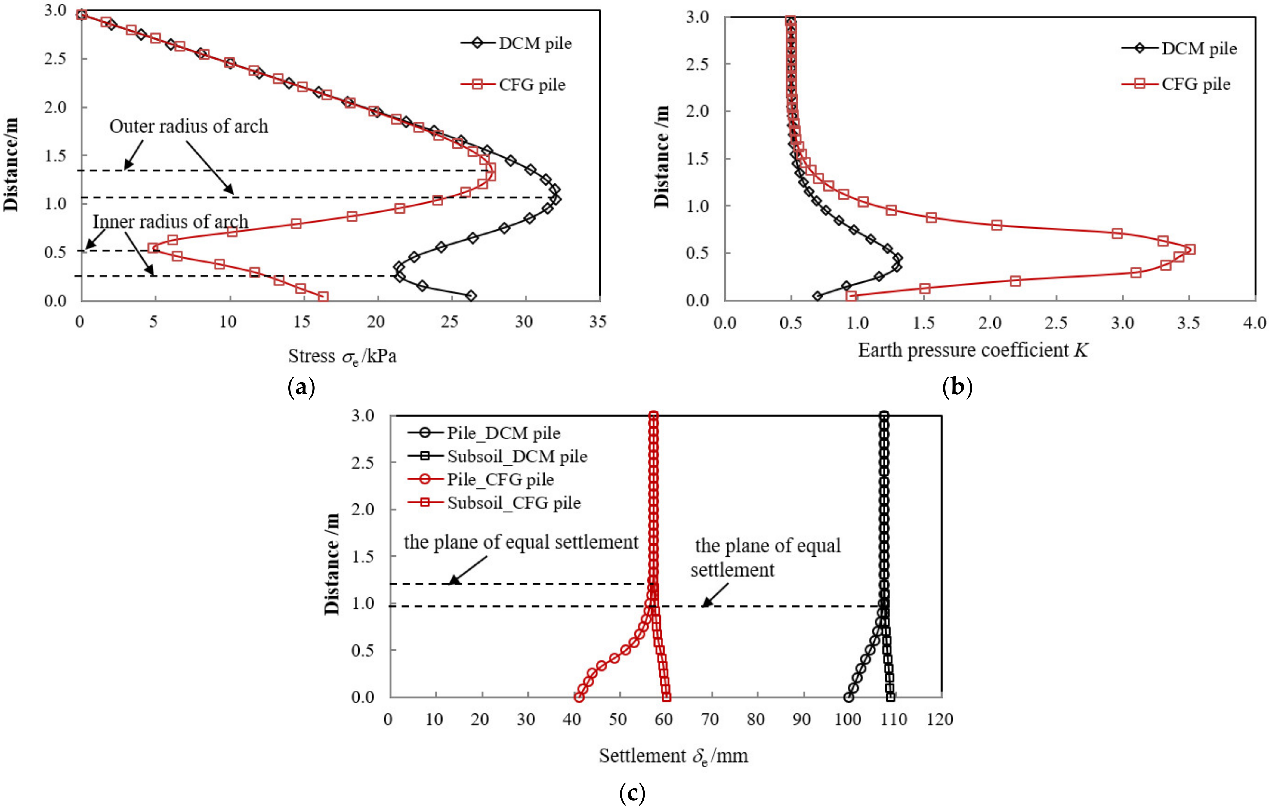
3.5. Comparison between DCM Piled Foundation and Rigid Piled Foundation

Based on this numerical model, a comparison analysis of the load transfer mechanism was conducted between the DCM piled foundation and rigid piled foundation (e.g., CFG piled foundation). In the comparison analysis, the embankment height h was taken as 3.0 m (e.g., h/(sa) = 3.0, where s is the pile spacing and a is the diameter of the DCM pile) so that the soil arching could fully generate, as the existing research (e.g., Zhuang [32]) implied that full arching can occur when h/(s − a) is larger than 2.0. The elastic modulus of the CFG pile Ep is taken as 10 GPa, which is 200 times of that for the DCM pile. Figure 5 shows the difference of the working performance between the DCM and CFG piled foundation.
Figure 5a describes the distribution of the vertical stress σe of the embankment along a vertical profile through the center between DCM piles. The curves in Figure 5a initially show the same gradient (equal to the unit weight of the embankment) until reaching the height of the outer radius of the arch. Due to the effect of soil arching, the vertical stress σe then begins to reduce until it reaches the height of inner radius of the arch. Below the inner arch radius, the vertical stress σe gradually increases. The distribution of the vertical stress σe captured the same tendency both for the DCM and CFG piled foundation, whereas the height of the outer arch radius for the CFG piled foundation is larger than that of DCM piled foundation. This induced an approximately 61.5% larger vertical stress transferred to the surface of the subsoil of the DCM piled foundation compared with CFG piled foundation, as revealed in Figure 5a.
The distribution of the earth pressure coefficient K could provide a good illustration of the load transfer of the lateral and the vertical stress in the embankment. Figure 5b shows the profiles of the earth pressure coefficient K above the base of embankment. These two types of composite foundation show similar general patterns of behavior. It also reveals that the earth pressure coefficient of the CFG piled foundation reached Kp (Rankine passive values of K, Kp = (1 + sinφ)/(1 − sinφ) = 3.0 in this study) at the inner arch radius, whereas the maximum value of K for the DCM piled foundation was approximately 1.4, much less than Kp. Under the effect of soil arching, the vertical stress at the crown of the arch trends to be transferred to the lateral direction, which will induce an increasing earth pressure coefficient K. Thus, compared with the CFG piled embankment, it was found that the decrease in the earth pressure coefficient K in the DCM piled embankment implies a reduced soil arching effect. However, for the condition with the same geometry of the embankment and the pile (e.g., h/(sa) = 3.0 both for DCM and CFG piled foundation), soil arching could fully generate in the rigid piled embankment. Hence, the factors which influence the soil arching in the DCM piled foundation need to be further investigated.
Figure 5c presents the detailed distribution of the settlement of the embankment δe along a vertical profile through the center of DCM piles and the center between the DCM piles. Above the equal settlement plane, the settlement δe is found to be identical. This indicates that the soil is not disturbed above this plane. On the other hand, the settlement through center of the DCM pile gradually reduces below this plane, while that through the center between DCM piles raises to the maximum value. The settlement δe in terms of the DCM piled foundation is approximately 83–150% larger than that of the CFG piled foundation, which demonstrates that the stability of the DCM piled foundation needs more attention. To further understand the working mechanism of the DCM piled foundation, the parametric studies are discussed in the following sections.

4. Parametric Studies Results and Discussion

To clarify the influence of the load transfer mechanism in the DCM piled embankment and the stability of the embankment, the parameter sensitivity of the piles and the embankment was investigated, including the elastic modulus Ep and length L of the DCM piles, the area replacement ratio as, and the embankment height h. In addition, the dynamic response of the DCM piled foundation subjected to the cyclic load was also analyzed. Finally, the modification equation of the normalized vertical stress acting on the subsoil surface σs for DCM piled foundation was proposed according to the numerical results, and validated by the measured results in two field cases. The details of the investigated factors are listed in Table 3.

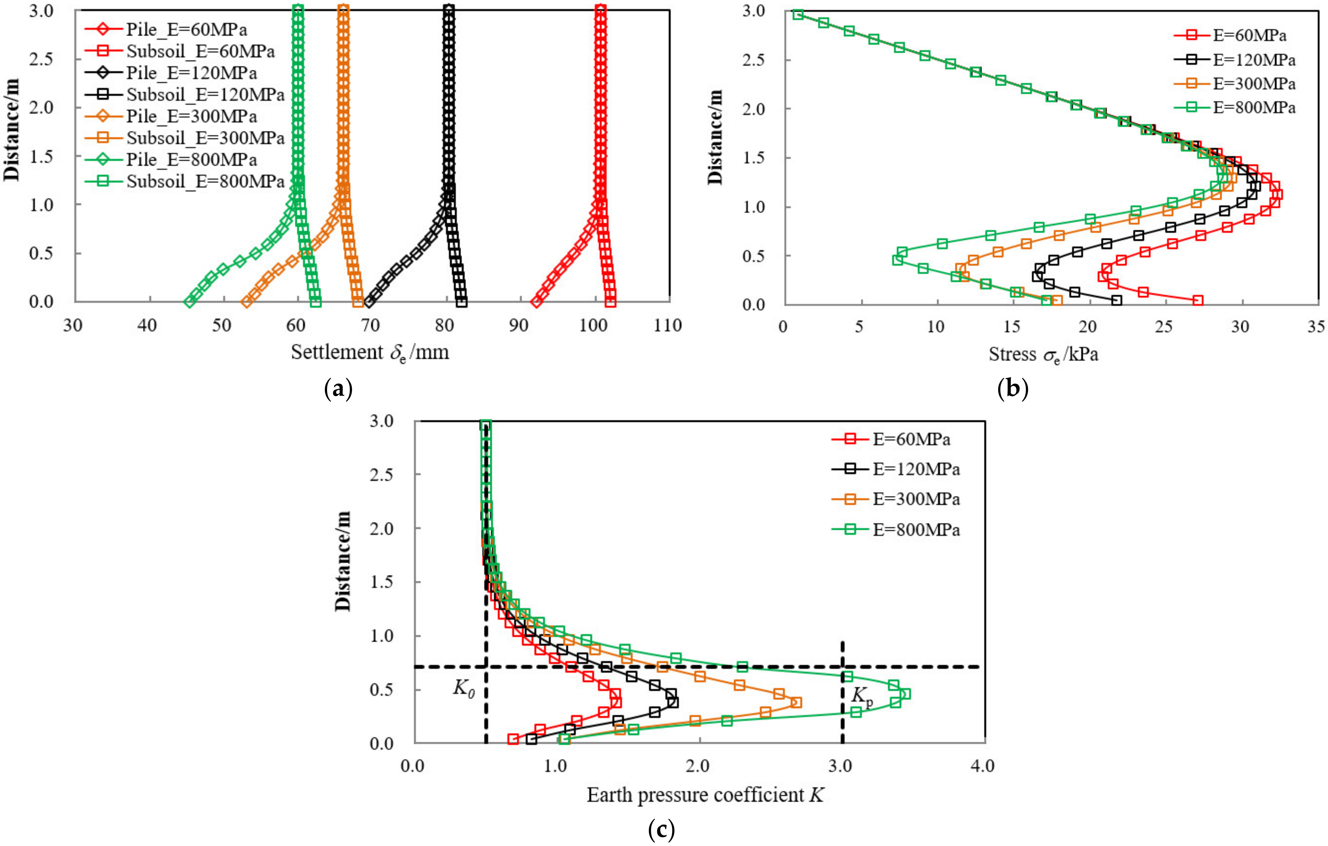
4.1. Influences of Elastic Modulus of DCM Piles

Figure 6a–c, respectively, illustrate the influences of the elastic modulus of the DCM piles Ep on the distribution of settlement δe, the vertical stress σe, and the earth pressure coefficient K of the embankment. Figure 6a displays the distribution of settlement through a vertical profile between DCM piles. It is clear that the settlement evolution decreased with the increasing elastic modulus of the DCM pile Ep. An increase in Ep from 60 MPa to 300 MPa (e.g., five times increased) results in a 34% decrease in the settlement at the top of the embankment. By increasing Ep from 60 MPa to 800 MPa (e.g., 13 times increased), the settlement can be reduced by approximately 40%. The variation of the differential settlement δ at the bottom of the embankment between the subsoil and the DCM pile was also observed, which is increased by approximately 70% with the increase in the elastic modulus of the DCM piles Ep (e.g., 13 times increased). This is attributed to the difference in the elastic modulus between the DCM pile and the subsoil.
The differential elastic modulus between the subsoil and the DCM pile will also induce the change of the magnitude of the earth pressure coefficient K and the vertical stress σe as illustrated in Figure 6b,c. As for the vertical stress at the surface of the subsoil σs (or the base of the embankment), it was decreased by approximately 20% with an increase of 200% in the elastic modulus of the DCM piles, and decreased by approximately 34% and 36% with increases of 500% and 1300% in the elastic modulus of the DCM piles, respectively. This indicates that the gradient of the vertical stress at the bottom of embankment decreases with increasing Ep, and will approach a limit value as Ep of the DCM piles increases to a certain value (e.g., 300 MPa in this case study).
As far as the earth pressure coefficient K was concerned, it is observed that the value of K is greatly influenced by increasing the value of Ep. For the condition that the value of Ep = 60 or 120 MPa, the maximum value of K is 1.4 and 1.7, respectively, much less than the Rankine passive values Kp = 3. This demonstrates that the soil arching is reduced, which results in an approximately 23~45% increase in the vertical stress transferred to the surface of subsoil, as displayed in Figure 6b, while for the condition that Ep = 300 or 800 MPa, the maximum earth pressure coefficient of the DCM piled foundation reached 2.75 and 3.50, respectively, at the inner radius of the arch, which is close to the value of Kp. The soil arching is fully generated when the elastic modulus Ep of the DCM pile reaches 300 or 800 MPa in this study. It can be concluded that the elastic modulus Ep of the DCM piles is one of the key factors to influence the development of soil arching in the DCM piled foundation.

4.2. Influence of the Length of DCM Piles

Figure 7 illustrates the influences of the DCM pile’s length L on the distribution of settlement δe, the vertical stress σe, and the earth pressure coefficient K of the embankment. An increase in L from 8 m to 20 m (e.g., 1.5 times increase) results in a 37% decrease in the settlement at the top of the embankment, and also leads to about 16~39% reduction in the settlement at the surface of the subsoil, while the differential settlement δ at the bottom of embankment varies slightly with the increasing length L of the DCM piles. Since the differential settlement of δ is the main reason for the generation of soil arching (a key factor of the load transfer in piled embankments), this may lead to the stable tendency for the distribution and the magnitude of the vertical stress σe and the earth pressure coefficient K, as illustrated in Figure 7b,c.

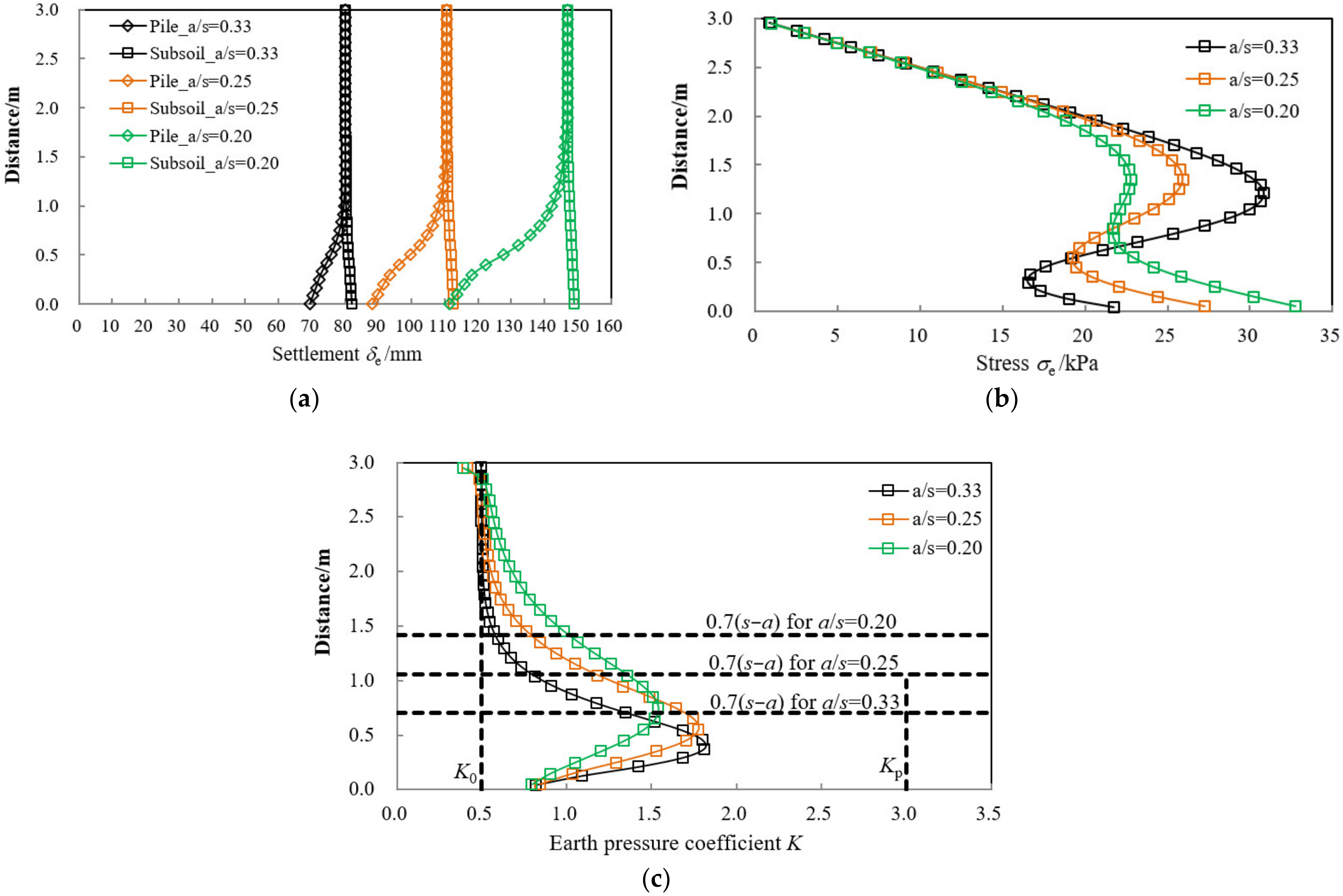
4.3. Influence of the Area Replacement Ratio

This subsection focuses on the influence of the area replacement ratio on the vertical stress σe, the distribution of settlement δe, and the earth pressure coefficient K of the embankment, as illustrated in Figure 8. The area replacement ratio as represents the ratio of the DCM piles area to the whole area of the influence unit cell, taken as as = Ac/(Ac + As), where Ac and As, respectively, denote the horizontal area of the DCM pile and the subsoil surrounding the DCM piles. An increase in as from 0.20 to 0.33 (e.g., 1.5 times increase) leads to a 45% decrease in the settlement at the top of the embankment. The differential settlement δ is reduced by 35% with the increase from 0.20 to 0.25, and reduced by 67% with a rise in as from 0.20 to 0.33. The distribution and the magnitude of the vertical stress along the embankment height were also influenced by increasing as, as shown in Figure 8b. The 65% rise in as resulted in the approximately 34% reduction of the vertical stress at the surface of the subsoil σs. Also observed in Figure 8c, the maximum earth pressure coefficient increased gradually with increasing as, and approaches the value of 2.0 (33% less then KP). Hence, it can be concluded that the area replacement ratio as is also one of the important factors which influence the development of soil arching in DCM piled foundations, whereas its effect is slightly smaller than the elastic modulus of the DCM pile.

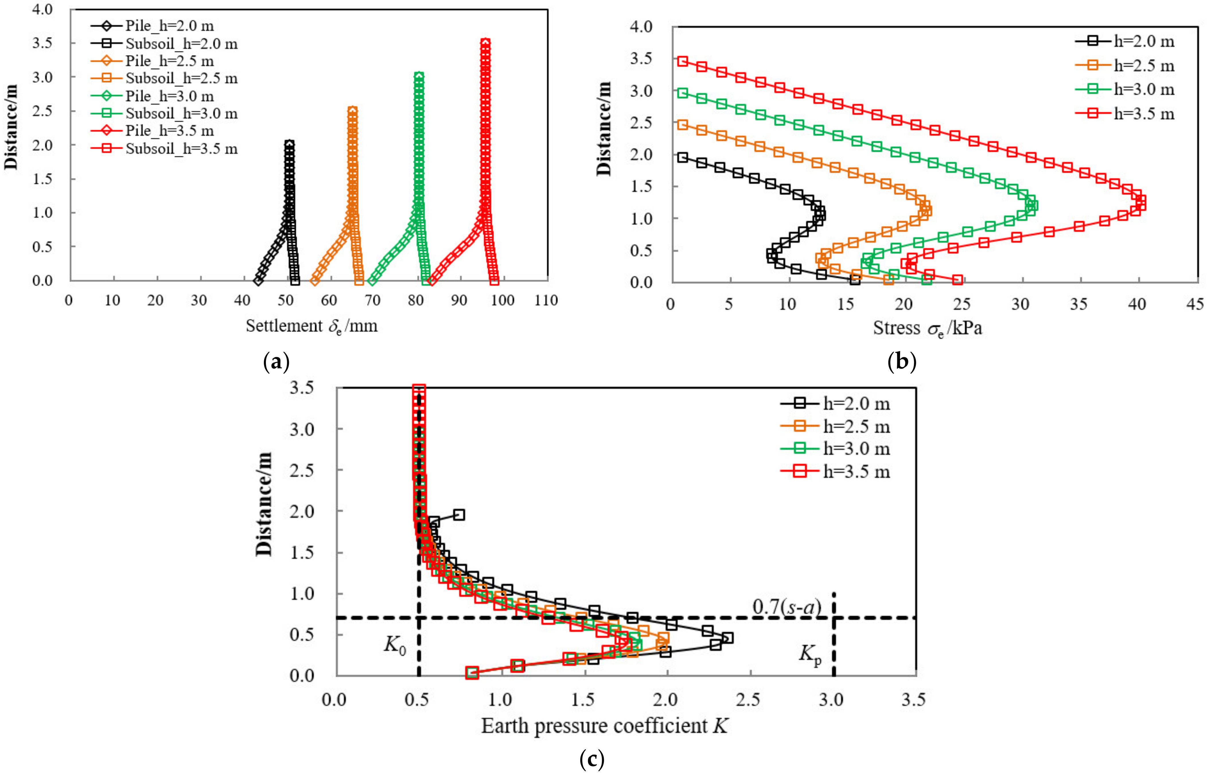
4.4. Influences of Embankment Height

Figure 9a–c illustrate the effect of the embankment height h on the distribution of settlement δe, the vertical stress σe, and the earth pressure coefficient K of the embankment. It is observed that a reduction in h from 3.5 to 2.0 (e.g., 43% reduction in h) leads to an approximately 43% decrease in the embankment settlement. Also seen in Figure 9a is that the height of the equal settlement plane increased about 25% with an increase of 75% in the embankment height. This will result in less stress from embankment overloading transferred on the surface of subsoil, e.g., σs = 0.34 γh for h = 3.5 m, as seen in Figure 9b. The maximum value of K decreases approximately 27% with the 75% increase in the value of h, which implies that the variation of embankment height h can influence soil arching generation in DCM piled foundations, whereas its effects is not significant compared with the elastic modulus of the DCM pile Ep as well.

4.5. Influences of Vehicle Speeds

The effect of the variation of vehicle speeds v on the distribution of the settlement δe, vertical stress σe, and the earth pressure coefficient K of the embankment is shown in Figure 10. It can be seen that the cyclic load induces a rise in the embankment settlement in Figure 10a. For the case of vehicle speeds v of 60 km/h, the settlement at the top of the embankment was increased by approximately 21%, and the maximum settlement at the base of the embankment increased by approximately 20%. When the vehicle speeds v reached 90 km/h, the settlement at the embankment top and base increased by approximately 34%. As shown in Figure 10b, the vertical stress in the embankment is increased by approximately 4% due to the cyclic load. Also found in Figure 10c, the maximum earth pressure coefficient K decreases under the cyclic load, with the value reduced by approximately 8% and 11% for the vehicle speeds v of 60 km/h and 90 km/h, respectively. This demonstrates that the soil arching influence is reduced for the embankment subjected to cyclic loads.
Comparing the results depicted in Figure 6, Figure 7, Figure 8, Figure 9 and Figure 10, the area replacement ratio as is found to be the most influential factor affecting the settlement at the top of the embankment, whereas the elastic modulus of the DCM pile Ep emerges as the most influential factor affecting the distribution and magnitude of the earth pressure coefficient and the vertical stress along a vertical profile through the center between DCM piles.

5. Modification of the Stress Reduction Ratio (SRR) Based on the Numerical Results

The stress reduction ratio SRR denotes the ratio of the average vertical stress σs applied on the surface of the subsoil at the center of the piles to the overburden vertical stress due to the embankment weight γh and surcharge on the embankment q0. It can be written in the following form:
S R R = σ s γ   h + q 0
According to previous parametric studies, the stress reduction ratio SRR in DCM piled foundations was proposed considering the effect of the elastic modulus Ep of the DCM pile, the embankment height h, and the area replacement ratio as. Figure 11 shows the proposed stress reduction ratio SRR with the variation of (Ep/Es) × (h/(sa)). The formulation of SRR can be given as follows:
S R R = 0.664 [ E p E s H ( s a ) ] 0.21
It can be found that the relationship between the stress reduction ratio SRR and the variable quantity of (Ep/Es) × (h/(sa)) exhibits as a power function shown in Figure 11. The value of the root mean squared error (RMSE) and the mean absolute error (MAE) for the proposed equation are calculated as 0.046 and 0.040, respectively.
Here, two reported field cases are introduced to validate the proposed equation of the stress reduction ratio SRR in DCM piled foundations. The value of the SRR for the field case in Thailand reported by Jamsawang [6] is 0.58, as shown in Figure 11, which is consistent with the results calculated by the proposed equation, having a difference of approximately 13.8%. In this Figure, the field case reported by Liu [4] was also presented, in which the ratio of the elastic modulus between the DCM pile and the top layer of subsoil Ep/Es = 5.0, embankment height h = 4.2 m, and the diameter of the DCM pile a = 0.5 m with a spacing s = 1.4 m. The measured SRR from the field case of Liu [4] is close to the calculated results derived from Equation 2, with the difference of approximately 16.7%. It is clear that predicted results by the proposed formulation agrees well with the measured one, with reasonable differences in the range of 13.8~16.7%. Therefore, the proposed equation can provide a reliable evaluation for the vertical stress acting on the subsoil surface in DCM piled foundation with reasonable accuracy.

6. Conclusions

Limited studies have focused on the load transfer mechanism of DCM piled embankment systems. For this purpose, a series of three-dimensional finite element models were analyzed in this study. The variation of the settlement, vertical stress, and the earth pressure coefficient under different influencing factors were reported and discussed, and the following conclusions can be obtained:
(1)
The difference in the working performance between the DCM piled and rigid piled embankment was observed. The effect of soil arching was greatly reduced in the DCM piled embankment. This induced approximately 61.5% more vertical stress transferred to the subsoil surface and approximately 83–150% more settlement of the embankment in the DCM piled foundation system.
(2)
The variation law of the embankment settlement: Macroscopically, increasing the elastic modulus of DCM piles, the length of DCM piles, the area replacement ratio, and reducing the embankment height can decrease the settlement of the embankment. The area replacement ratio is found to be the most influential factor affecting the embankment settlement.
(3)
Load transfer efficacy: The rise in the elastic modulus of the DCM piles, the length of the DCM piles, the area replacement ratio, and embankment height will increase the load transfer efficacy. The elastic modulus of the DCM pile emerges as the most influential factor affecting the distribution and magnitude of the vertical stress and the maximum earth pressure coefficient, followed by embankment height and area replacement ratio, and the length of DCM piles have a slight effect on the load transfer efficacy.
(4)
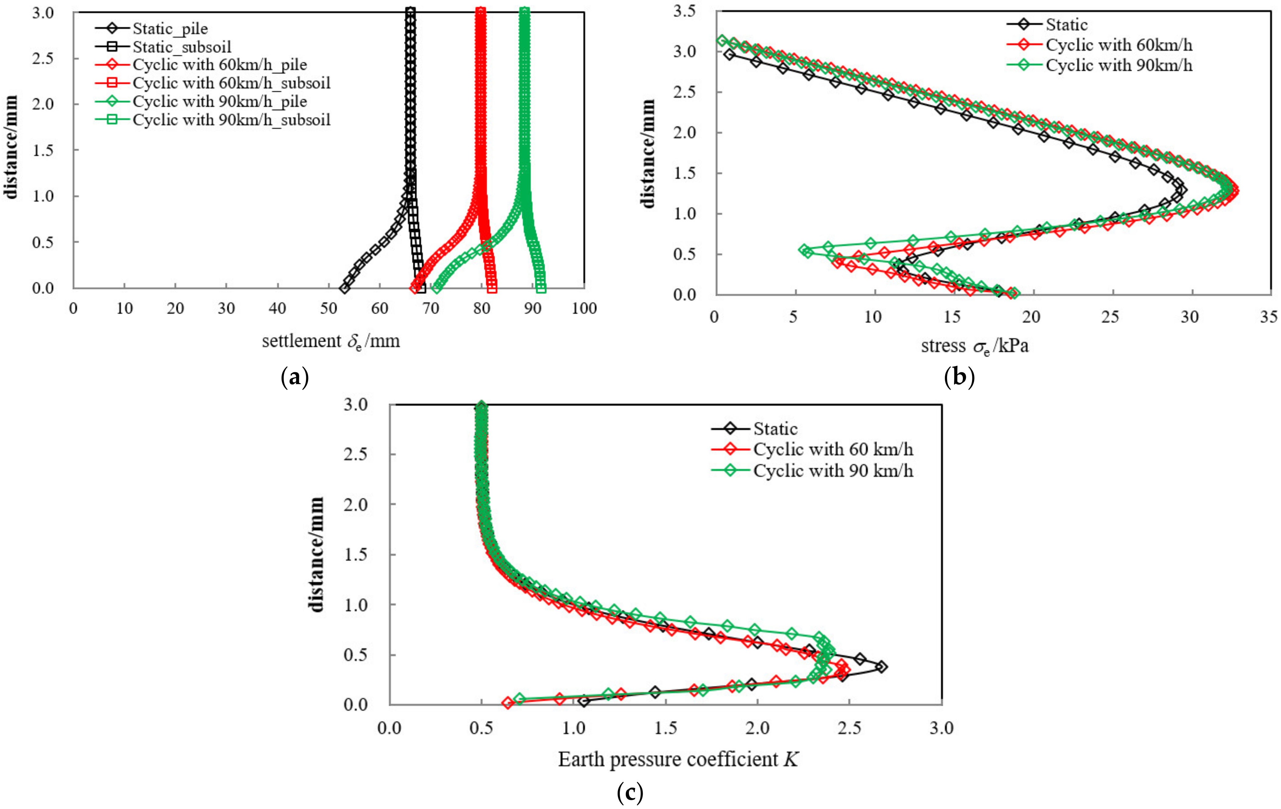
The effect of soil arching is reduced when the embankment is subjected to cyclic loads. A cyclic load with the vehicle speed of 90 km/h will lead to an approximately 34% increase in embankment settlement and an approximately 11% reduction in the maximum earth pressure coefficient.
(5)
The stress reduction ratio for DCM piled foundations was proposed and validated by two field cases, with differences in the range of 13.8~16.7%. Therefore, the proposed equation can provide a reliable evaluation on the vertical stress at the surface of the subsoil for DCM piled foundations with reasonable accuracy.
In this study, the working mechanism of a DCM piled foundation was studied using numerical simulations. Based on the research findings, the following suggestions are given: For the design of DCM piled embankments, the elastic modulus of the DCM pile can be adjusted to achieve the maximum economic benefit and also reach to the requirement of load transfer efficacy. Moreover, the settlement and the stress state of the DCM piled embankment system relate to the ratio of the elastic modulus of the DCM piles to the surrounding subsoil’s elastic modulus Ep/Es, which should be taken into consideration in the design of the embankment. The proposed equation for the stress reduction ratio can give a fast and reliable estimation for the vertical stress acting on the surface of subsoil, which is easy to use in practice.

Author Contributions

Conceptualization, X.C.; methodology, X.C.; software, X.C. and Y.C.; writing—original draft preparation, X.C.; writing—review and ending, Y.C. and Y.J.; funding acquisition, X.C. and Y.C.; validation, Y.J. All authors have read and agreed to the published version of the manuscript.

Funding

The financial support of the National Natural Science Foundation for Distinguished Young Scholar of China (Grant No. 52108306), Nature Science Foundation of Jiangsu Province, China (Grant No. BK20200372) and the Systematic Project of Guangxi Key Laboratory of Disaster Prevention and Engineering Safety (Grant No. 2020ZDK009) is acknowledged.

Institutional Review Board Statement

Not applicable.

Informed Consent Statement

Not applicable.

Data Availability Statement

All the data are already provided in the main manuscript. Contact the corresponding author if further explanation is required.

Conflicts of Interest

The authors declare no conflict of interest.

References

  1. Yapage, N.N.S.; Liyanapathirana, D.S.; Kelly, R.B.; Poulos, H.G.; Leo, C.J. Numerical modeling of an embankment over soft ground improved with deep cement mixed columns: Case history. J. Geotech. Geoenviron. Eng. 2014, 140, 04014062. [Google Scholar] [CrossRef]
  2. Zhuang, Y.; Wang, K.Y. Numerical simulation of high-speed railway foundation improved by PVD-DCM method and compared with field measurements. Eur. J. Environ. Civ. Eng. 2017, 21, 1363–1383. [Google Scholar] [CrossRef]
  3. Han, J.; Oztoprak, S.; Parsons, R.L.; Huang, J. Numerical analysis of foundation columns to support widening of embankments. Comput. Geotech. 2007, 34, 435–448. [Google Scholar] [CrossRef]
  4. Liu, S.Y.; Du, Y.J.; Yi, Y.L.; Puppala, A.J. Field investigations on performance of T-shaped deep mixed soil cement column-supported embankments over soft ground. J. Geotech. Geoenviron. Eng. 2012, 138, 718–727. [Google Scholar] [CrossRef]
  5. Terashi, M.; Ooya, T.; Fujita, T.; Okami, T.; Yokoi, K.; Shinkawa, N. Specifications of Japanese dry methods of deep mixing deduced from 4300 projects on land. In Proceedings of the International Symposium on Deep Mixing & Admixture Stabilization, Okinawa, Japan, 19 May 2009; pp. 647–652. [Google Scholar]
  6. Jamsawang, P.; Yoobanpot, N.; Thanasisathit, N.; Voottipruex, P.; Jongpradist, P. Three-dimensional numerical analysis of a DCM column-supported highway embankment. Comput. Geotech. 2016, 72, 42–56. [Google Scholar] [CrossRef]
  7. Voottipruex, P.; Bergado, D.T.; Suksawat, T.; Jamsawang, P.; Cheang, W. Behavior and simulation of deep cement mixing (DCM) and stiffened deep cement mixing (SDCM) piles under full scale loading. Soils Found. 2011, 51, 307–320. [Google Scholar] [CrossRef] [Green Version]
  8. Jiang, Y.; Han, J.; Zheng, G. Numerical analysis of consolidation of soft soils fully-penetrated by deep-mixed columns. KSCE J. Civ. Eng. 2013, 17, 96–105. [Google Scholar] [CrossRef]
  9. Jamsawang, P.; Voottipruex, P.; Boathong, P.; Mairaing, W.; Horpibulsuk, S. Three-dimensional numerical investigation on lateral movement and factor of safety of slopes stabilized with deep cement mixing column rows. Eng. Geol. 2015, 188, 159–167. [Google Scholar] [CrossRef]
  10. Yi, Y.L.; Liu, S.Y.; Puppala, A.J.; Xi, P.S. Vertical bearing capacity behaviour of single T-shaped soil-cement column in soft ground: Laboratory modelling, field test, and calculation. Acta Geotech. 2017, 12, 1077–1088. [Google Scholar] [CrossRef]
  11. Phutthananon, C.; Jongpradist, P.; Yensri, P.; Jamsawang, P. Dependence of ultimate bearing capacity and failure behavior of T-shaped deep cement mixing piles on enlarged cap shape and pile strength. Comput. Geotech. 2018, 97, 27–41. [Google Scholar] [CrossRef]
  12. Phutthananon, C.; Jongpradist, P.; Jongpradist, P.; Dias, D.; Baroth, J. Parametric analysis and optimization of T-shaped and conventional deep cement mixing column-supported embankments. Comput. Geotech. 2020, 122, 103555. [Google Scholar] [CrossRef]
  13. Hewlett, W.J.; Randolph, M.F. Analysis of piled embankments. Ground Eng. 1988, 21, 12–18. [Google Scholar]
  14. Zhang, L.; Zhao, M.H.; Hu, Y.X.; Zhao, H.; Chen, B.C. Semi-analytical solutions for geosynthetic-reinforced and pile-supported embankment. Comput. Geotech. 2012, 44, 167–175. [Google Scholar] [CrossRef]
  15. Van Eekelen, S.J.M.; Bezuijen, A.; Van Tol, A.F. An analytical model for arching in piled embankments. Geotext. Geomembr. 2013, 39, 78–102. [Google Scholar] [CrossRef]
  16. Zhuang, Y.; Wang, K.Y.; Liu, H.L. A simplified model to analyze the reinforced piled embankments. Geotext. Geomembr. 2014, 42, 154–165. [Google Scholar] [CrossRef]
  17. Nguyen, V.D.; Luo, Q.; Wang, T.F.; Liu, K.F.; Zhang, L.; Nguyen, T.P. Load transfer in geosynthetic-reinforced piled embankments with a triangular arrangement of piles. J. Geotech. Geoenviron. Eng. 2023, 149, 04022131. [Google Scholar] [CrossRef]
  18. Indraratna, B.; Basack, S.; Rujikiatkamjorn, C. Numerical solution of stone column–improved soft soil considering arching, clogging, and smear effects. J. Geotech. Geoenviron. Eng. 2013, 139, 377–394. [Google Scholar] [CrossRef] [Green Version]
  19. Liu, K.W.; Rowe, R.K. Numerical study of the effects of geosynthetic rein-forcement viscosity on behaviour of embankments supported by deep-mixing method columns. Geotext. Geomembr. 2015, 43, 567–578. [Google Scholar] [CrossRef]
  20. Wang, X.; Wang, X.; Yang, G.; Zong, Y. Study on Load Transfer Mechanism of Pile-Supported Embankment Based on Response Surface Method. Appl. Sci. 2022, 12, 4905. [Google Scholar] [CrossRef]
  21. Liu, H.L.; Ng, C.W.W.; Fei, K. Performance of a geogrid-reinforced and pile-supported highway embankment over soft clay: Case study. J. Geotech. Geoenviron. Eng. 2007, 113, 1483–1493. [Google Scholar] [CrossRef]
  22. Nunez, M.A.; Briançon, L.; Dias, D. Analyses of a pile-supported embankment over soft clay: Full-scale experiment, analytical and numerical approaches. Eng. Geol. 2013, 153, 53–67. [Google Scholar] [CrossRef]
  23. Zhao, M.X.; Liu, C.Y.; Tao, M.J. Performance of Geogrid-Reinforced and PTC Pile-Supported Embankment in a Highway Widening Project over Soft Soils. J. Geotech. Geoenviron. Eng. 2019, 145, 06019014. [Google Scholar] [CrossRef]
  24. Zhuang, Y.; Cui, X.Y.; Zhang, S.; Dai, G.L.; Zhao, X.L. The load transfer mechanism in reinforced piled embankment under cyclic loading and unloading. Eur. J. Environ. Civ. Eng. 2022, 26, 1364–1378. [Google Scholar] [CrossRef]
  25. Chango, I.V.L.; Yan, M.; Ling, X.; Liang, T.; Assogba, O.C. Dynamic response analysis of geogrid reinforced embankment supported by CFG pile structure during a high-speed train operation. Lat. Am. J. Solids Struct. 2019, 16, e214. [Google Scholar] [CrossRef] [Green Version]
  26. Chen, Y.M.; Ma, S.N.; Ren, Y.; Chen, R.P.; Biao, X.C. Experimental study on cyclic settlement of piles in silt soil and its application in high-speed railway design. Transp. Geotech. 2021, 27, 100496. [Google Scholar] [CrossRef]
  27. Vipulanandan, C.; Mohammed, A.S. Comparison between Mohr-Coulomb failure criterion and Vipulanandan failure models to predict the maximum J_2 Invariant and behaviour of clay (CH). Geomech. Geoeng. 2022, 17, 1905–1922. [Google Scholar] [CrossRef]
  28. Isleem, H.F.; Augustino, D.S.; Mohammed, A.S.; Najemalden, A.M.; Jagadesh, P.; Qaidi, S.; Sabri, M.M.S. Finite element, analytical, artificial neural network models for carbon fibre reinforced polymer confined concrete filled steel columns with elliptical cross sections. Front. Mater. 2023, 9, 1115394. [Google Scholar] [CrossRef]
  29. Vipulanandan, C.; Krishnamoorti, R.; Mohammed, A.; Boncan, V.; Narvaez, G.; Hughes, B.; Head, B.; Pappas, J.M. Iron Nanoparticle Modified Smart Cement for Real Time Monitoring of Ultra Deepwater Oil Well Cementing Applications. In Proceedings of the Offshore Technology Conference, Houston, TX, USA, 4–7 May 2015; pp. 2216–2231. [Google Scholar]
  30. Zhang, Y.M.; Liang, B. Dynamic response of expressway subgrade under geometric irregularity conditions. J. Lanzhou Jiaotong Univ. 2001, 20, 66–69. [Google Scholar]
  31. Potyondy, J.G. Skin friction between various soils and construction materials. Géotechnique 1961, 11, 339–353. [Google Scholar] [CrossRef]
  32. Zhuang, Y. Numerical Modelling of Arching in Piled Embankments including the Effects of Reinforcement and Soil. Ph.D. Dissertation, The University of Nottingham, Nottingham, UK, 2009. [Google Scholar]
Figure 1. Flow chart for the work process.
Sustainability 15 06532 g001
Figure 2. Cross-section of the DCM pile-supported embankment.
Sustainability 15 06532 g002
Figure 3. Three-dimensional finite element model of the DCM pile-supported embankment.
Sustainability 15 06532 g003
Figure 4. Validation of the numerical model. (a) Settlement at the surface of the subsoil δs. (b) The vertical stress at the centerline of the subsoil σs.
Sustainability 15 06532 g004
Figure 5. Comparison between the CFG and DCM piled embankments. (a) The distribution of the vertical stress of the embankment σe. (b) The distribution of the earth pressure coefficient K. (c) The distribution of the settlement of the embankment δe.
Sustainability 15 06532 g005
Figure 6. Influence of the elastic modulus of DCM piles. (a) The distribution of the settlement of the embankment δe. (b) The distribution of the vertical stress of the embankment σe. (c) The distribution of the earth pressure coefficient K.
Sustainability 15 06532 g006
Figure 7. Influence of the length of DCM piles. (a) The distribution of the settlement of the embankment δe. (b) The distribution of the vertical stress of the embankment σe. (c) The distribution of the earth pressure coefficient K.
Sustainability 15 06532 g007
Figure 8. Influence of the area replacement ratio. (a) The distribution of the settlement of the embankment δe. (b) The distribution of the vertical stress of the embankment σe. (c) The distribution of the earth pressure coefficient K.
Sustainability 15 06532 g008
Figure 9. Influence of the embankment height. (a) The distribution of the settlement of the embankment δe. (b) The distribution of the vertical stress of the embankment σe. (c) The distribution of the earth pressure coefficient K.
Sustainability 15 06532 g009
Figure 10. Influence of the vehicle speeds. (a) The distribution of the settlement of the embankment δe. (b) The distribution of the vertical stress of the embankment σe. (c) The distribution of the earth pressure coefficient K.
Sustainability 15 06532 g010
Figure 11. Modification of the stress reduction ratio SRR based on the numerical results [4,6].
Sustainability 15 06532 g011
Table 1. Summary of the parameters of the embankment and DCM pile.
MaterialUnit Weight γ (kN/m3)Elastic Modulus E (MPa)Poisson’s Ratio νCohesion c (kPa)Friction Angle φ (Degree)Permeability Coefficient k (m/d)
Embankment20200.33130--
DCM pile15800.33Cu = 45005 × 10−4
Table 2. Summary of the parameters of the soft soils.
Fill MaterialSoft ClayMedium-Stiff Clay
Unit weight, γ (kN/m3)201416
Compression index, λ--0.180.12
Swelling index, κ--0.040.06
Poisson’s ratio, ν 0.300.350.15
Cohesion, c (kPa)1110
Friction angle, φ (degree)322325
Permeability coefficient, k (m/d)--5 × 10−42.5 × 10−4
Table 3. Main parameters used in the simulations.
NumberPile Spacing s/mPile Cap Width a/mArea Replacement Ratio asEmbankment Height h/mLength of the DCM Pile L/mElastic Modulus of the DCM Pile Ep/MPaVehicle Speed v/km/h
12.50.50.23.0141200
22.00.50.253.0141200
31.50.50.333.0141200
41.50.50.332.0141200
51.50.50.332.5141200
61.50.50.333.5141200
71.50.50.333.081200
81.50.50.333.0101200
91.50.50.333.0201200
101.50.50.333.014600
111.50.50.333.0143000
121.50.50.333.0148000
131.50.50.333.01430060
141.50.50.333.01430090
Disclaimer/Publisher’s Note: The statements, opinions and data contained in all publications are solely those of the individual author(s) and contributor(s) and not of MDPI and/or the editor(s). MDPI and/or the editor(s) disclaim responsibility for any injury to people or property resulting from any ideas, methods, instructions or products referred to in the content.

