
Performance Study of Casing Piles in Expansive Soil Foundations: Model Testing and Analysis


Abstract
:1. Introduction
2. Experimental Setup
2.1. Preparation of Expansive Soil
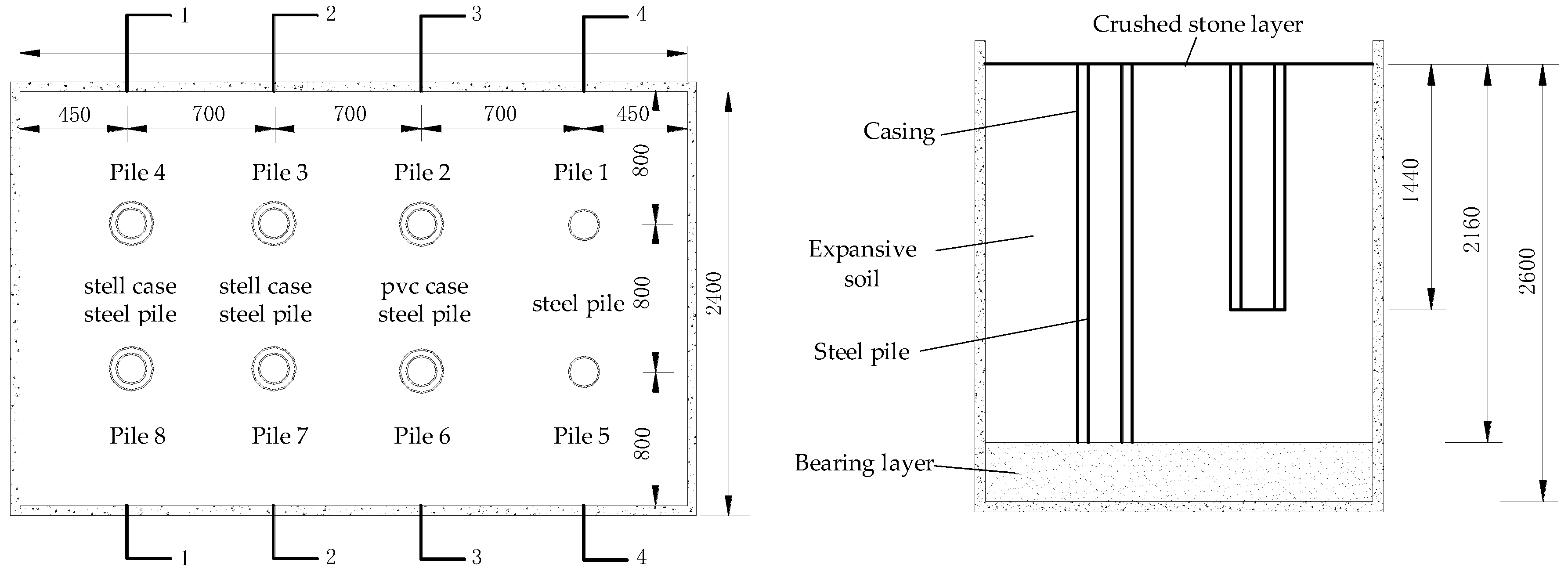
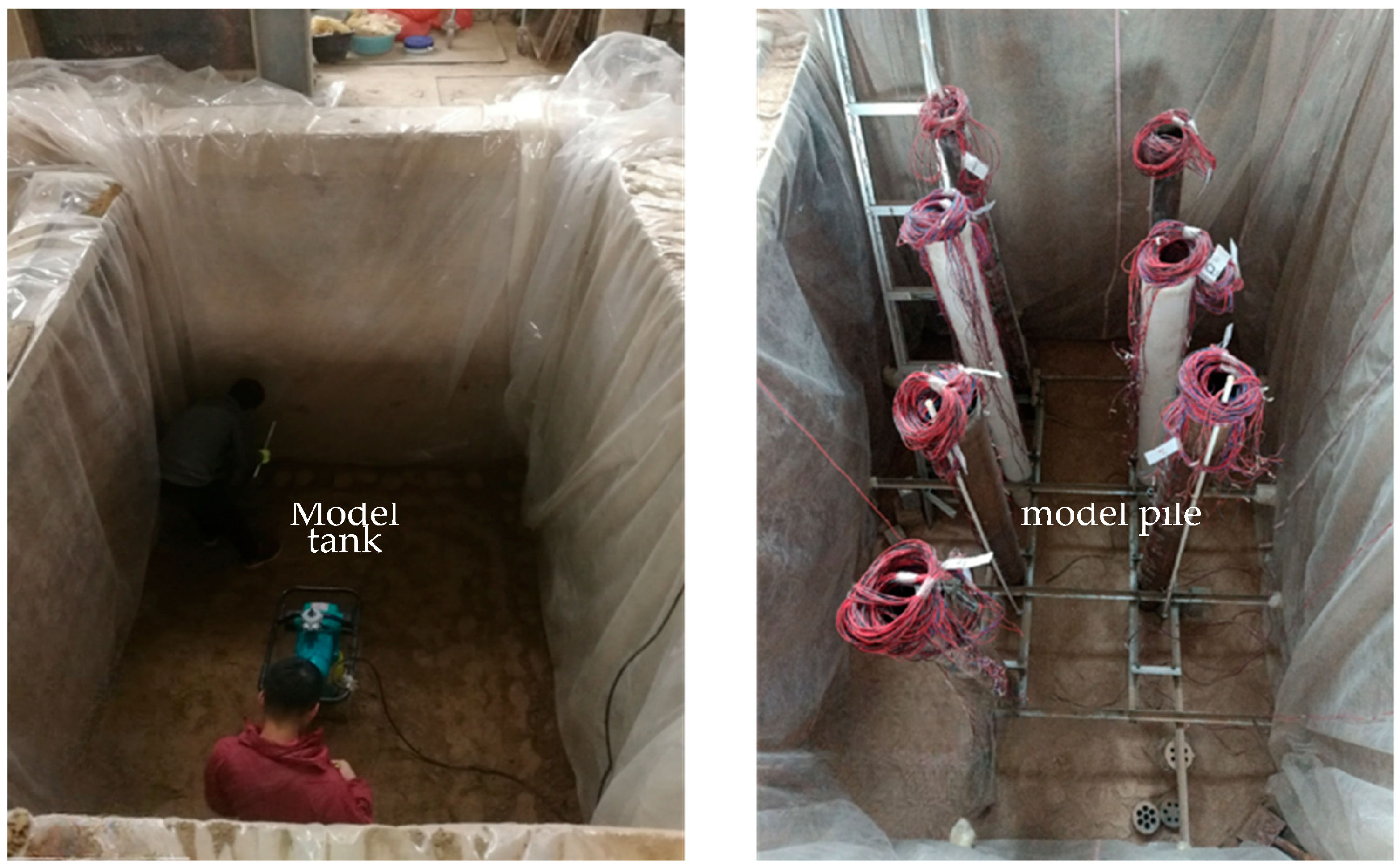
2.2. Model Piles
2.3. Experimental Design and Steps
- (1)
- In the model tank, a 44 mm-thick layer of gravel was first placed at the bottom as a load-bearing layer. An electric compaction machine was used to lightly compact the sand layer at intervals of 110 mm to achieve a density of 1.7 g/cm3. Prefabricated model piles were suspended in their designated positions by ropes. Limiting frames were installed at the bottom of the test tank to provide stable support for the piles. The verticality of each pile was ensured using the drop hammer suspension method. After the installation of the model piles was completed, a 2160 mm-thick layer of artificially prepared expansive soil was placed. The compaction degree of the expansive soil was controlled to 0.95 using the ring cutting method. To ensure uniform percolation of water without surface ponding, a 50 mm layer of crushed stone was placed on the surface of the expansive soil.
- (2)
- Slow loading maintenance was applied to piles 1–4. Pile 1 was directly loaded, while piles 2, 3, and 4 were loaded through their inner piles. A loading system consisting of a reaction beam and hydraulic jacks was used to gradually apply the experimental load. Pile 1 was loaded at 2 kN per stage, while piles 2, 3, and 4 were loaded at 1 kN per stage. For pile 8, a mechanical jack was set up to measure the upward expansion force exerted on the pile body by the expansive soil model material upon contact with water.
- (3)
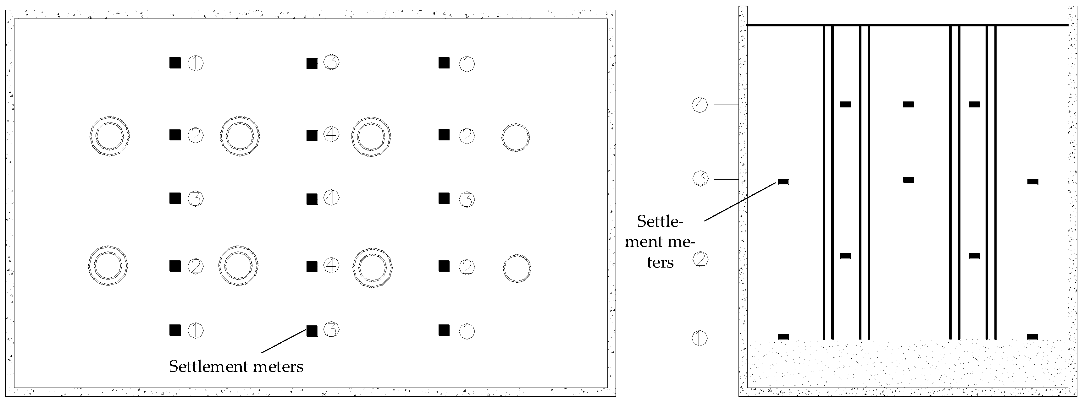
- The immersion test was initiated when the pile top settlements reached an average of 4 mm, indicating that the piles were under normal load conditions. Settlement measurements at the pile top were taken at the 5th, 15th, 30th, 45th, and 60th minutes. Subsequently, settlement measurements were taken every 30 min. When the settlement rate at the pile top reached a relatively stable state (settling at less than 0.1 mm/h for two consecutive measurements), the next level of load is applied.
3. Results and Discussion
3.1. Pile Bearing Characteristics before Immersion
3.2. Deformation of the Pile–Soil System after Immersion
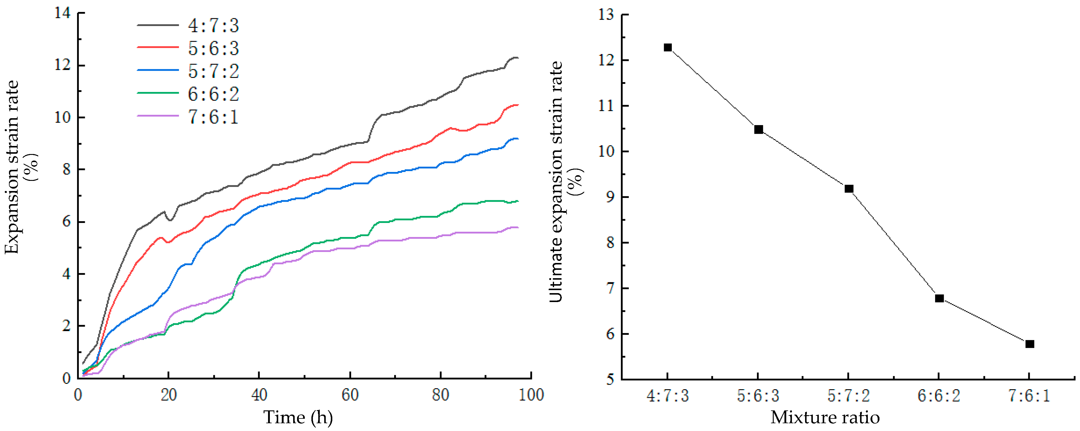
3.2.1. Soil Expansion Characteristics
3.2.2. Pile Head Displacement
3.3. Pile Bearing Characteristics after Immersion
3.3.1. Without Additional Surface Loading
3.3.2. With Additional Surface Loading
4. Conclusions
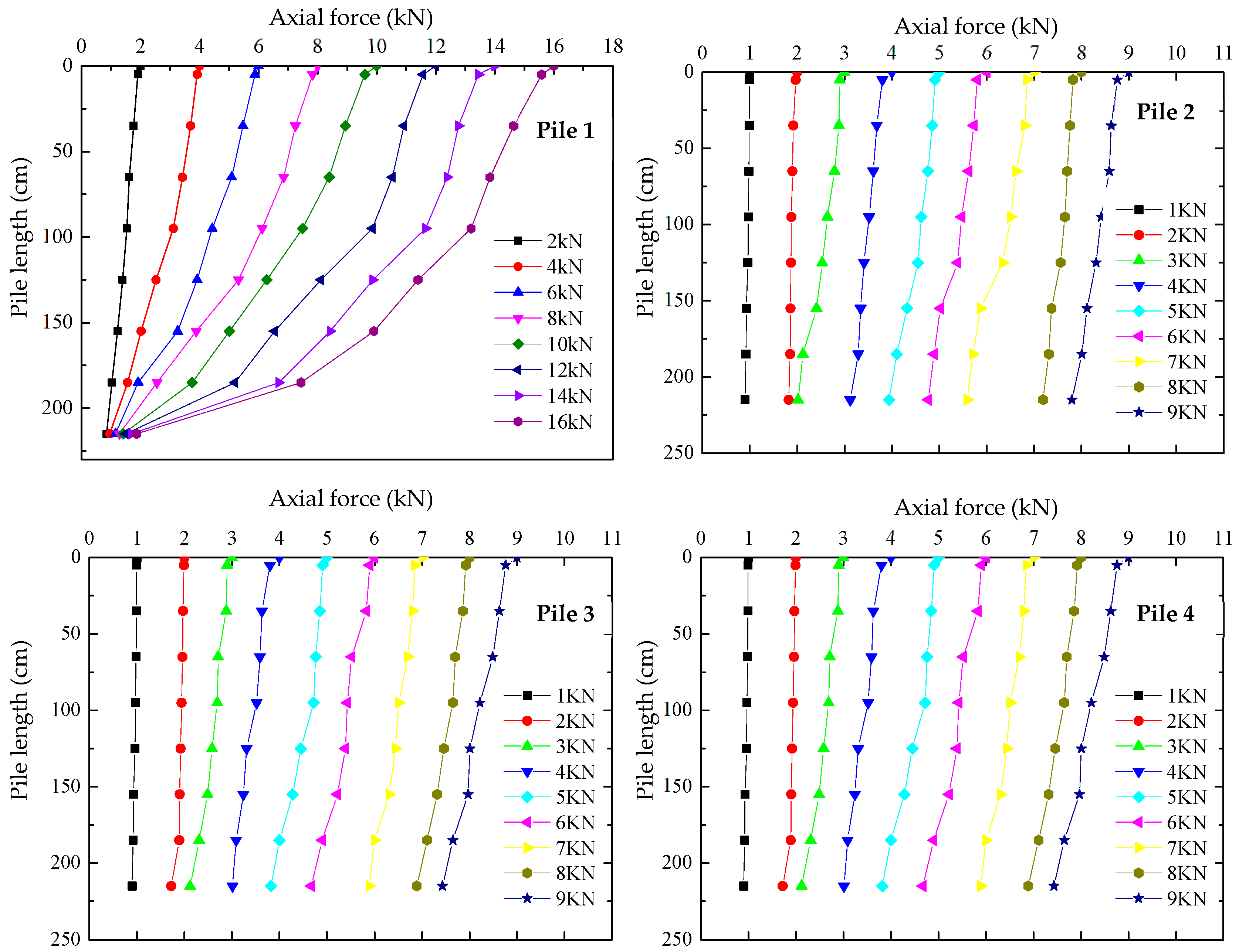
- (1)
- Before immersion, uncased piles under loading exhibited typical friction pile characteristics, with axial forces primarily concentrated in the upper portion. In contrast, PVC-casing and steel-casing piles effectively reduced side frictional resistance, resulting in a more uniform distribution of axial force along the pile shaft.
- (2)
- After immersion, the model test materials underwent expansion. Soil expansion deformation was divided into two phases: an initial rapid rise phase with a significant expansion rate and a later gradual rise phase where the expansion rate stabilized. The uncased pile (pile 1) has the highest ultimate bearing capacity, exceeding the cased piles (piles 2, 3, and 4) by 7 kN.
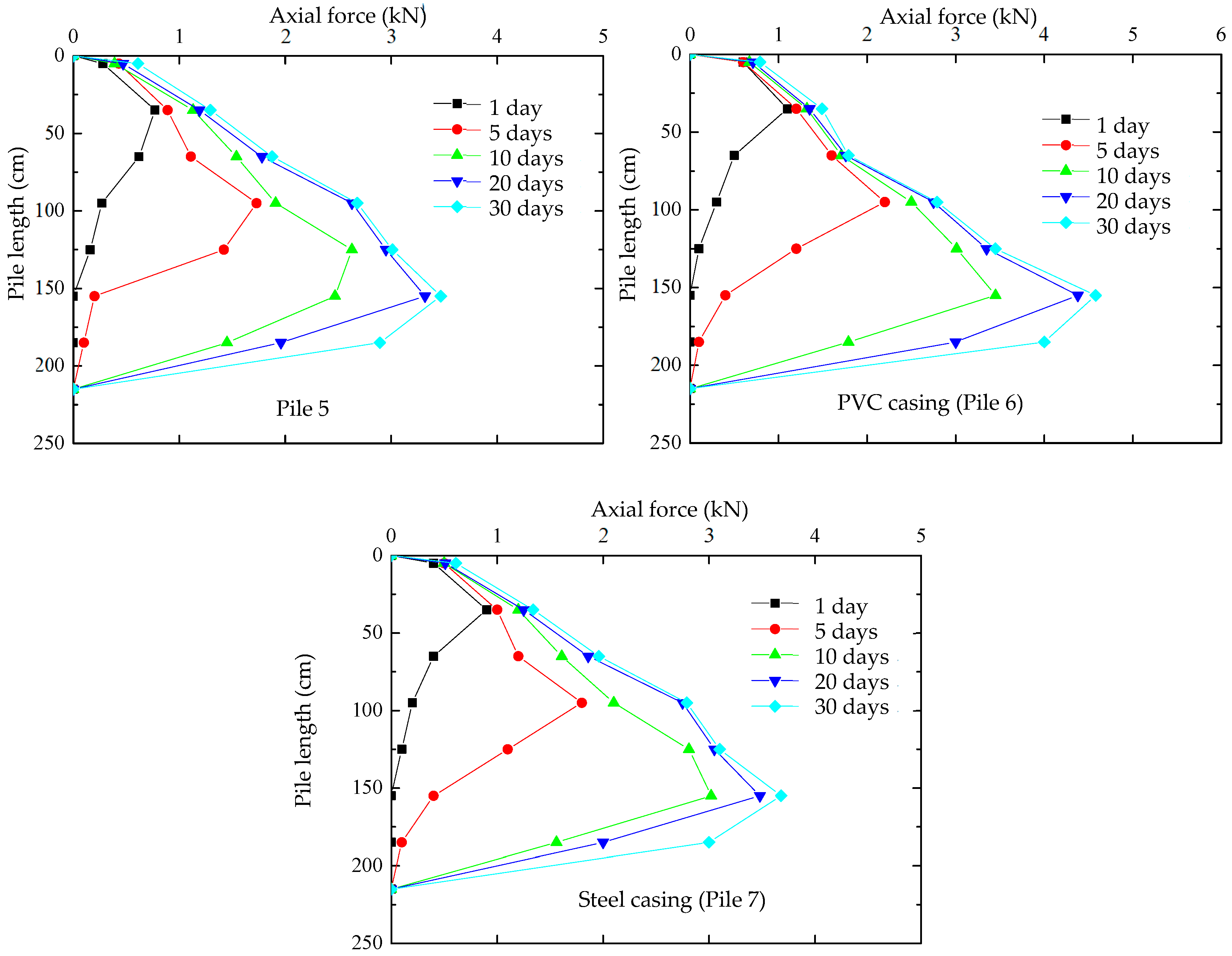
- (3)
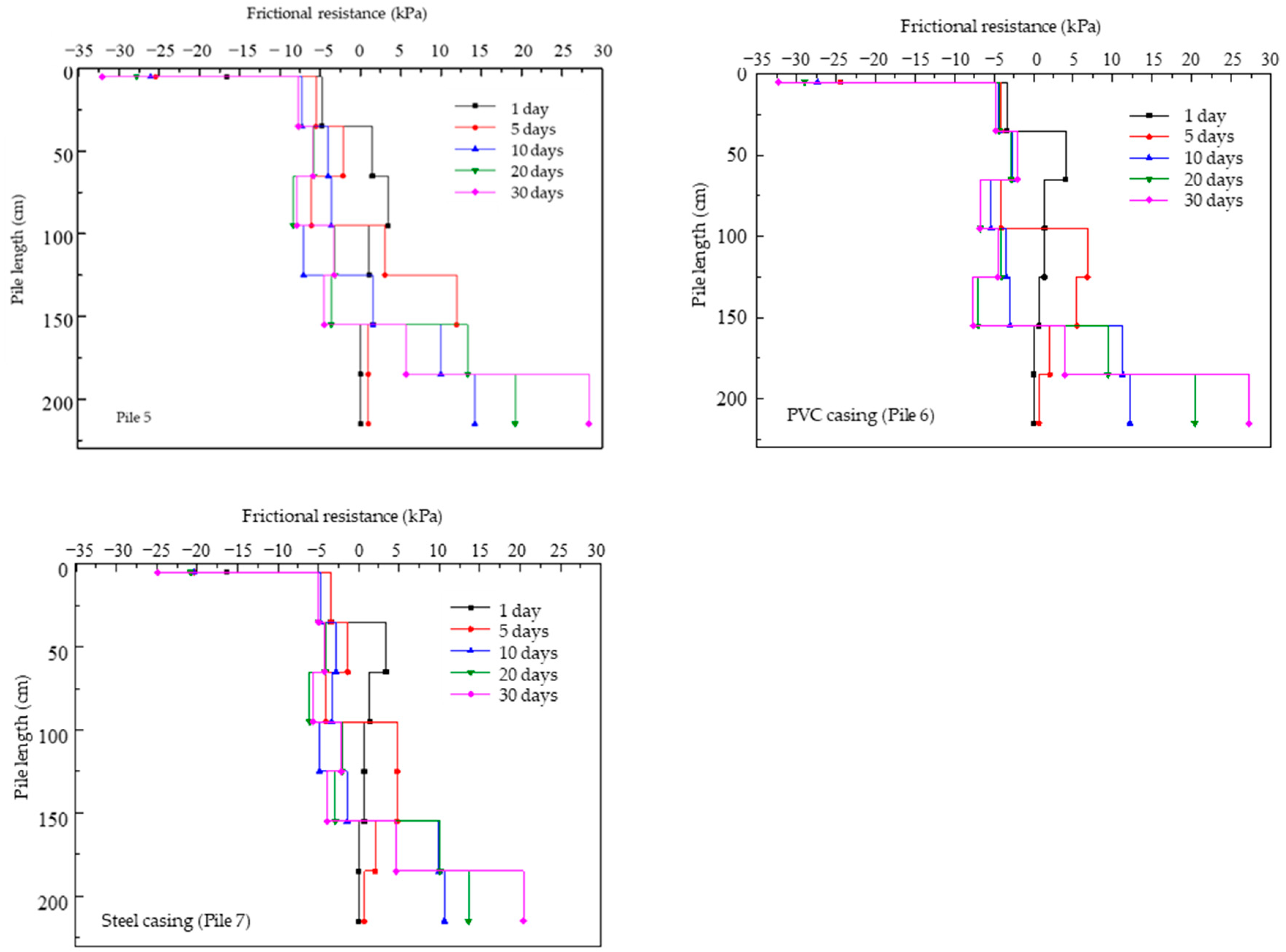
- Under the immersion condition with without additional pile top loads, the pile displacement caused by soil absorption expansion increases, and the presence of an outer casing reduces the upward displacement of the inner pile. The axial forces in the casing piles exhibit an initial increase followed by a decrease, with the peak axial force being highest in the PVC casing. The expansive soil, 720 mm thick, exerts an expansion stress of 108 kPa on the model piles. The positive and negative frictional resistance of the casing piles alternate along the length of the pile, with the neutral point of the model pile located at 160 mm from the top.
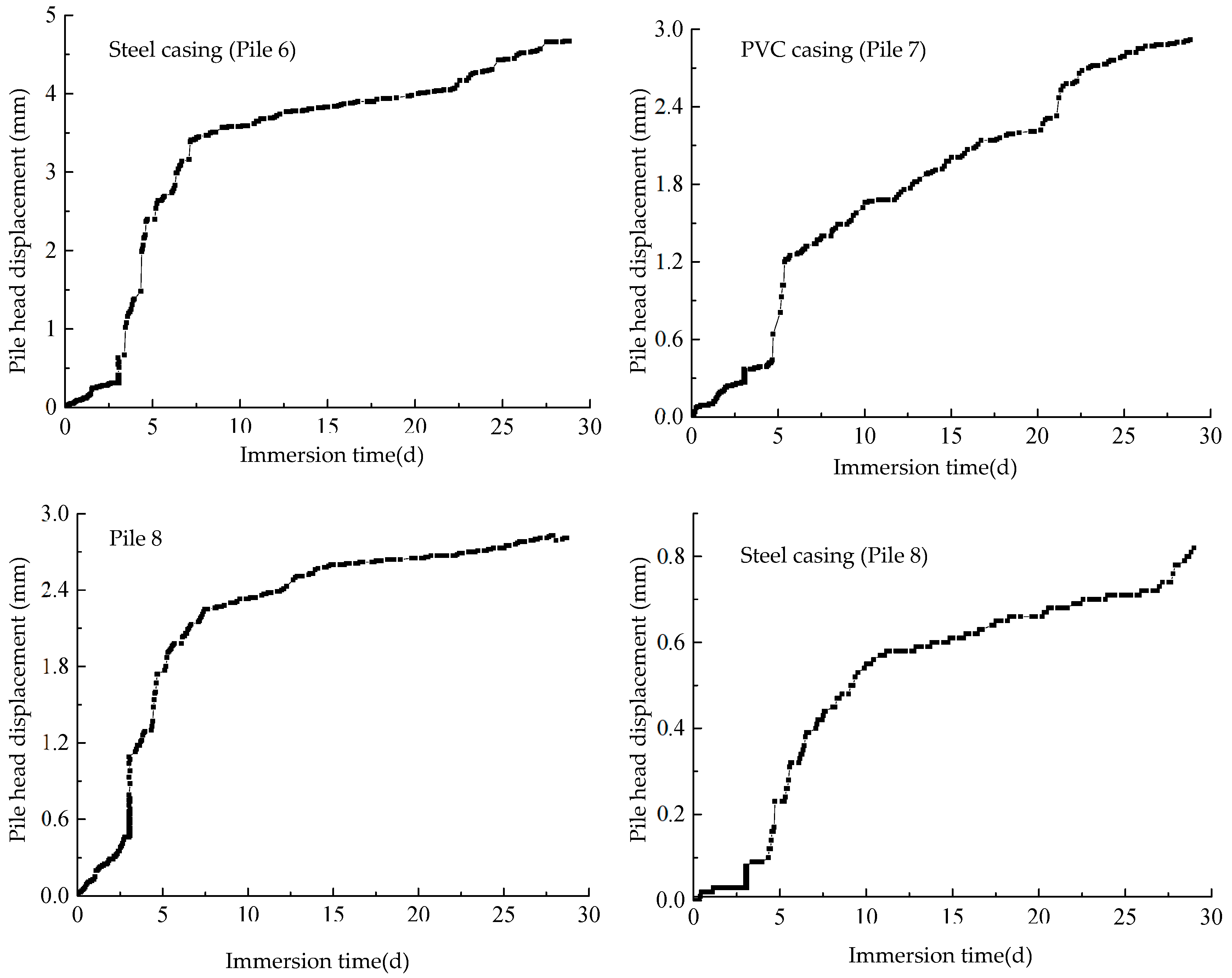
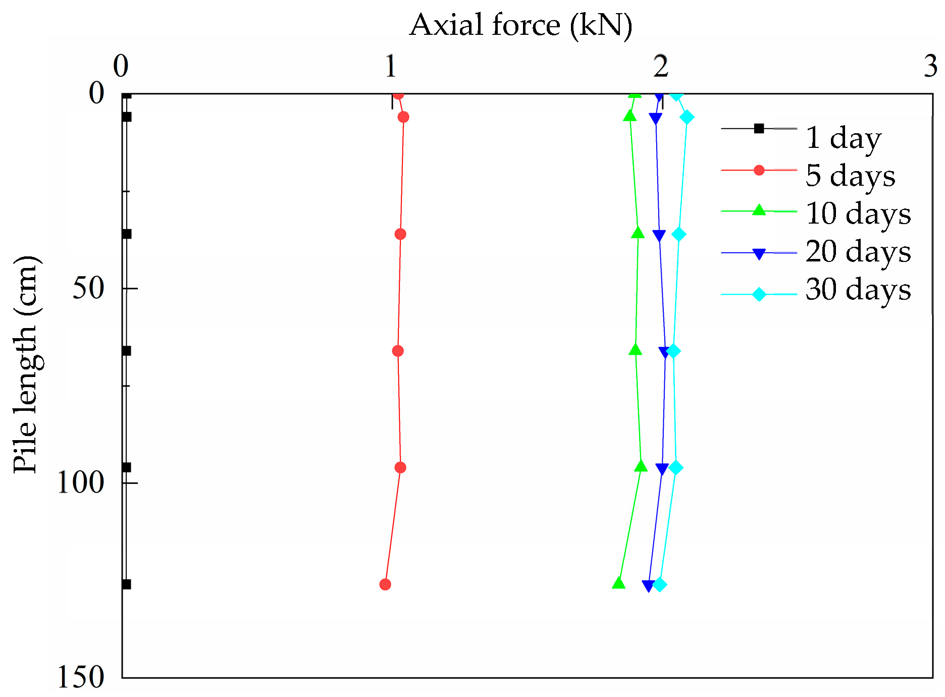
- (4)
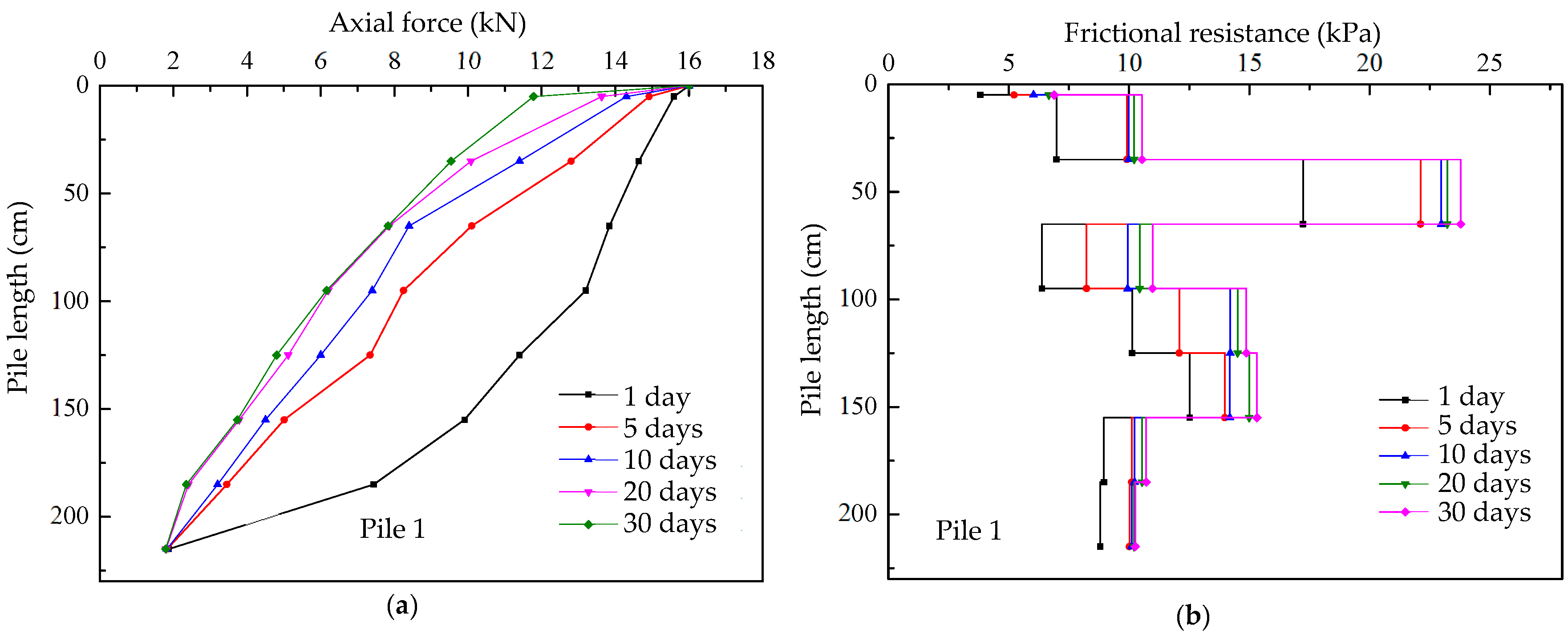
- Under the immersion condition with additional pile top load, with additional pile top loads, uncased pile displacement changes the least, while cased piles (including steel casing and PVC casing piles) exhibit displacement changes approximately four times that of uncased piles. The axial forces along the depth of pile 1 decrease rapidly, and the side frictional resistance of the pile is positive friction and increases with the increase in immersion time.
- (5)
- From the analysis of pile–soil deformation, it is evident that casing piles effectively mitigate the impact of expansive soil on pile displacement, reducing the risk of foundation damage in expansive soil areas. Among the casing types, PVC casings provided the most effective treatment compared to bare and steel-casing piles.
Author Contributions
Funding
Institutional Review Board Statement
Informed Consent Statement
Data Availability Statement
Conflicts of Interest
References
- Ikeagwuani, C.C.; Nwonu, D.C. Emerging trends in expansive soil stabilisation: A review. J. Rock Mech. Geotech. Eng. 2019, 11, 423–440. [Google Scholar] [CrossRef]
- Sahoo, S.; Prasad Singh, S. Strength and durability properties of expansive soil treated with geopolymer and conventional stabilizers. Constr. Build. Mater. 2022, 328, 127078. [Google Scholar] [CrossRef]
- Seco, A.; Ramírez, F.; Miqueleiz, L.; García, B. Stabilization of expansive soils for use in construction. Appl. Clay Sci. 2011, 51, 348–352. [Google Scholar] [CrossRef]
- Jiang, J.; Hou, K.; Ou, X. Analysis of the Bearing Capacity of a Single Pile Based on an Analytical Solution of Pile–Soil Interaction in Expansive Soil. Geotech. Geol. Eng. 2020, 38, 1721–1732. [Google Scholar] [CrossRef]
- Wang, N.X.; Gu, R.W.; Zhang, W.M.; Gu, X.W. Model tests on behaviour of single pile in expansive soil. Chin. J. Geotech. Eng. 2008, 30, 56–60. [Google Scholar]
- Fattah, M.Y.; Al-Omari, R.R.; Fadhil, S.H. Load sharing and behavior of single pile embedded in unsaturated swelling soil. Eur. J. Environ. Civ. Eng. 2020, 24, 1967–1992. [Google Scholar] [CrossRef]
- Hou, K.W.; Jiang, J.; Wang, S.W.; Ou, X.D. Physical Model Test and Theoretical Study on the Bearing Behavior of Pile in Expansive Soil Subjected to Water Infiltration. Int. J. Geomech. 2021, 21, 06021014. [Google Scholar] [CrossRef]
- Liu, Y.; Vanapalli, S.K. Load displacement analysis of a single pile in an unsaturated expansive soil. Comput. Geotech. 2019, 106, 83–98. [Google Scholar] [CrossRef]
- Ter-Martirosyan, Z.G.; Ter-Martirosyan, A.Z. Foundation and Pile Interaction with Swelling Soil. Soil Mech. Found. Eng. 2018, 55, 291–297. [Google Scholar] [CrossRef]
- Yang, L.; Ji, W.; Zhang, Y.; Ren, Q.; Shen, R. Analysis of Expansive Earth Pressure of Pile Foundation Under Repeated Immersion. Int. J. Civ. Eng. 2023, 21, 875–886. [Google Scholar] [CrossRef]
- Soundara, B.; Robinson, R.G. Hyperbolic model to evaluate uplift force on pile in expansive soils. KSCE J. Civ. Eng. 2017, 21, 746–751. [Google Scholar] [CrossRef]
- Mohamedzein, Y.E.; Mohamed, M.G.; El Sharief, A.M. Finite element analysis of short piles in expansive soils. Comput. Geotech. 1999, 24, 231–243. [Google Scholar] [CrossRef]
- Wu, X.; Vanapalli, S.K. Three-dimensional modeling of the mechanical behavior of a single pile in unsaturated expansive soils during infiltration. Comput. Geotech. 2022, 145, 104696. [Google Scholar] [CrossRef]
- Sharma, A.; Sharma, R.K. An experimental study on uplift behaviour of granular anchor pile in stabilized expansive soil. Int. J. Geotech. Eng. 2021, 15, 950–963. [Google Scholar] [CrossRef]
- Phanikumar, B.R.; Srirama Rao, A.; Suresh, K. Field behaviour of granular pile-anchors in expansive soils. Proc. Inst. Civ. Eng.-Ground Improv. 2008, 161, 199–206. [Google Scholar] [CrossRef]
- Albusoda, B.S.; Abbase, H.O. Performance assessment of single and group of helical piles embedded in expansive soil. Int. J. Geo-Eng. 2017, 8, 25. [Google Scholar] [CrossRef]


| Number of Piles | 1 | 2 | 3 | 4 | 5 | 6 | 7 | 8 | |
|---|---|---|---|---|---|---|---|---|---|
| Type | steel | steel | steel | steel | steel | steel | steel | steel | |
| Diameter (mm) | 108 | 108 | 108 | 108 | 108 | 108 | 108 | 108 | |
| Length (mm) | 2160 | 2160 | 2160 | 2160 | 2160 | 2160 | 2160 | 1440 | |
| Casing | Type | / | PVC | steel | steel | / | PVC | steel | steel |
| Length (mm) | / | 2160 | 2160 | 2160 | / | 2160 | 2160 | 1440 | |
| Diameter (mm) | / | 158 | 158 | 158 | / | 158 | 158 | 158 | |
Disclaimer/Publisher’s Note: The statements, opinions and data contained in all publications are solely those of the individual author(s) and contributor(s) and not of MDPI and/or the editor(s). MDPI and/or the editor(s) disclaim responsibility for any injury to people or property resulting from any ideas, methods, instructions or products referred to in the content. |
© 2023 by the authors. Licensee MDPI, Basel, Switzerland. This article is an open access article distributed under the terms and conditions of the Creative Commons Attribution (CC BY) license (https://creativecommons.org/licenses/by/4.0/).
Share and Cite
Li, Z.; Chen, T.; Chai, Q.; Shen, D.; Wu, C. Performance Study of Casing Piles in Expansive Soil Foundations: Model Testing and Analysis. Sustainability 2024, 16, 132. https://doi.org/10.3390/su16010132
Li Z, Chen T, Chai Q, Shen D, Wu C. Performance Study of Casing Piles in Expansive Soil Foundations: Model Testing and Analysis. Sustainability. 2024; 16(1):132. https://doi.org/10.3390/su16010132
Chicago/Turabian StyleLi, Zuoyong, Tianlei Chen, Qing Chai, Danyi Shen, and Chuangzhou Wu. 2024. "Performance Study of Casing Piles in Expansive Soil Foundations: Model Testing and Analysis" Sustainability 16, no. 1: 132. https://doi.org/10.3390/su16010132
APA StyleLi, Z., Chen, T., Chai, Q., Shen, D., & Wu, C. (2024). Performance Study of Casing Piles in Expansive Soil Foundations: Model Testing and Analysis. Sustainability, 16(1), 132. https://doi.org/10.3390/su16010132