Article

Numerical Analysis of Unsteady Internal Flow Characteristics in a Bidirectional Axial Flow Pump

School of Mechanical Engineering, Nantong University, Nantong 226019, China
*
Author to whom correspondence should be addressed.
Sustainability 2024, 16(1), 224; https://doi.org/10.3390/su16010224
Submission received: 13 November 2023 / Revised: 17 December 2023 / Accepted: 22 December 2023 / Published: 26 December 2023

Abstract

:
A bidirectional axial flow pump that utilizes an S-shaped hydrofoil design exhibits low efficiency and hydraulic instability when operated in reverse. In order to understand the unsteady flow characteristics of this bidirectional axial pump under different operating conditions, the SST kω turbulence model was applied to carry out a three-dimensional unsteady numerical simulation of the full flow channel of the pump. The reliability of the numerical calculation model was verified by comparing it with the experimental head and efficiency. The pressure pulsation characteristics on the impeller surface and the pump device under different operating conditions and the transient forces on the impeller were analyzed. The results show that the head and efficiency in reverse operation were lower than in forward operation and the flow streamline of the impeller outlet area was more turbulent in the reverse operation condition. The monitoring points at the inlet and the top of the impeller surface showed the largest pressure pulsation amplitude. The radial and axial forces on the impeller in the reverse operation were greater than those in the forward operation. Under a reverse 1.0 Qdes condition, the average pressure pulsation amplitudes at the inlet of the impeller were 19.2 times and 5.7 times of that at the inlet of the guide vane and the outlet of the impeller, respectively. This study provides a reference for the hydraulic design and optimization of bidirectional axial flow pumps.

1. Introduction

Axial flow pumps convert electrical energy into the kinetic and pressure energy of water by means of a motor-driven impeller [1]. Axial flow pumps are widely used in China’s South-to-North Water Diversion Project, playing an important role in agricultural irrigation, urban water supply and drainage, etc. [2,3]. Sustainability can be facilitated by the widespread use of axial flow pumps. However, traditional axial flow pumps are characterized by a high efficiency and stable operation under forward operating conditions, but the pumping station operates less efficiently and loses more resources under reverse operating conditions. To achieve the bidirectional transportation of water, the pumping station system is usually used in the following forms [4]. The first is the “one station, four gates” type of pumping station, which has two channels. In each channel, there are two restraining gates installed, through the adjustment of the restraining valve, to achieve the purpose of self-induction and self-discharge. More resources are required, and as land resources become more and more valuable and the structure of this type of pumping station is complicated and cumbersome, the advantages of this type of pumping station are also decreased. The second is to flip the direction of the pump body to achieve the purpose of the bidirectional transportation of water, but this operation is more complex, the procedure of turning the pump body is cumbersome, wasting more manpower and material resources, and it is not able to deal with emergencies properly [5]. The third type is the use of blades with bidirectional performance, which can change the direction of the rotation of the motor to irrigate and drain water. The advantages of this type of pumping station are a simple building structure, less space occupation, simple shape of the inlet and outlet runners, high efficiency in the forward and reverse directions, high stability and easy maintenance, so it is being more and more widely used in the construction of pumping stations that need to consider a bidirectional pump [6]. Axial pumps with bidirectional performance blades can be switched in different directions by simply adjusting the motor steering, which is the most convenient way to realize bidirectional operation and achieve large savings in human resources and energy [7]. With the increasing research on the S-airfoil shape, the energy characteristics of bidirectional axial pumps with S-airfoil blades have been improved upon to quite an extent [8,9,10]. Chen et al. investigated the distortion mechanism of inlet fluid and the energy characteristics of the fluid in a bidirectional axial flow pump and found that the non-uniform inflow of the fluid negatively affected the efficiency and head of the pumping device [11]. This was because of the bidirectional axial flow pump’s reverse operation on the structure of the impeller by the influence of the guide vane, showing different hydraulic performance [12,13]. Wang et al. investigated the internal flow of a bidirectional axial pump and found that flow separation at the blade tails during reverse operation resulted in performance degradation [14]. Axial flow pumps with bidirectional water suction promote sustainability by saving energy, increasing efficiency and reducing resource waste.
A growing number of researchers have concluded that pressure pulsations caused by unsteady flow in pumps have a significant influence on the safety and stability of pumping station systems [15,16,17]. The inlet flow pattern of a bidirectional axial flow pump is interfered with by the guide vanes in reverse, resulting in poor hydrodynamic efficiency of the pump. This means that bidirectional pumps produce more severe vibration and noise during their operation [18]. Zhang et al. investigated the fluid dynamic characteristics and pressure fluctuation of bidirectional axial flow pumps through physical model tests, revealing the propagation law of energy characteristics and pressure fluctuation of the pumps [19]. Kan et al. investigated the effects of vane tip clearance and operating conditions on energy loss and the leakage vortex in pumps, quantitatively studying the energy loss induced by the leakage vortex, and found a correlation between the leakage vortex and pressure and vorticity, revealing the spatial distribution characteristics and formation mechanism of the leakage vortex [20]. Guo et al. carried out unsteady numerical calculations for axial flow pumps at different rotational speeds to characterize the flow patterns and mechanisms of energy loss of the fluid in the pumping device [21]. Wu et al. investigated pressure pulsation and noise in a bidirectional pumping unit and found that pressure pulsation was related to flow rate while noise was more sensitive to blade frequency [22].
Bidirectional axial flow pumps produce more hydraulic instability in operation. At present, there are few studies on bidirectional axial pumps, their internal flow mechanism has not been fully grasped, and the design and optimization methods of bidirectional axial pumps are immature. A better understanding of the flow mechanism and pressure pulsation characteristics of bidirectional axial flow pumps under unsteady operating conditions is needed, which could be used to improve the operational stability of the pumps. The numerical simulation method was used to analyze the internal flow field of a bidirectional axial pump by unsteady numerical calculation and analysis of its unsteady flow characteristics. This paper provides a reference for the hydraulic design and optimization of a bidirectional axial pump.

2. Simulation Model and Numerical Method

2.1. Simulation Model

There are four main flow passage components of a bidirectional axial flow pump: the inlet and outlet conduits, impeller and guide vane. The main hydraulic components and full flow channel model of the bidirectional axial flow pump used in this study are shown in Figure 1. Table 1 shows the basic parameters of the bidirectional axial flow pump.

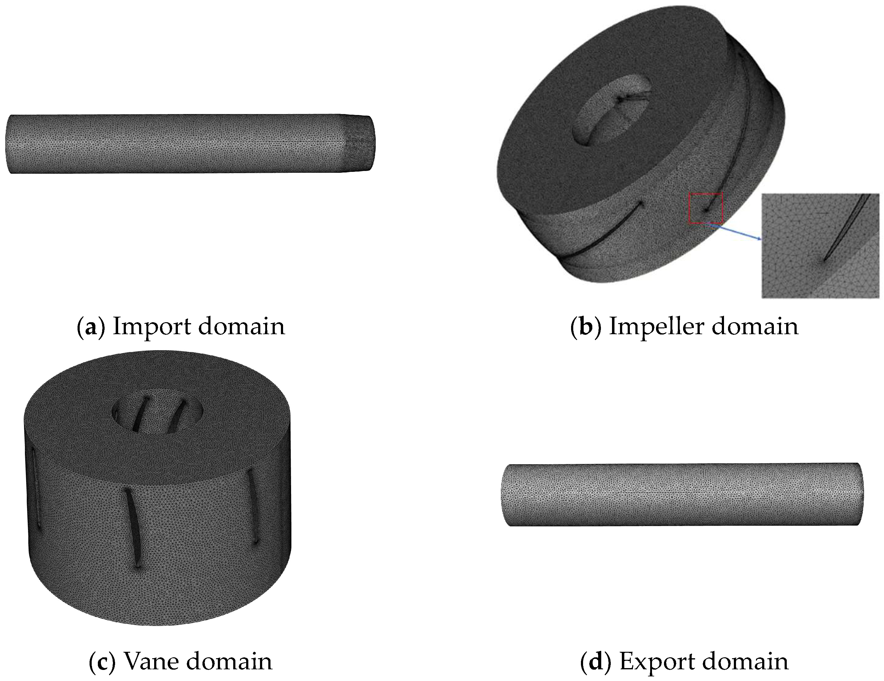
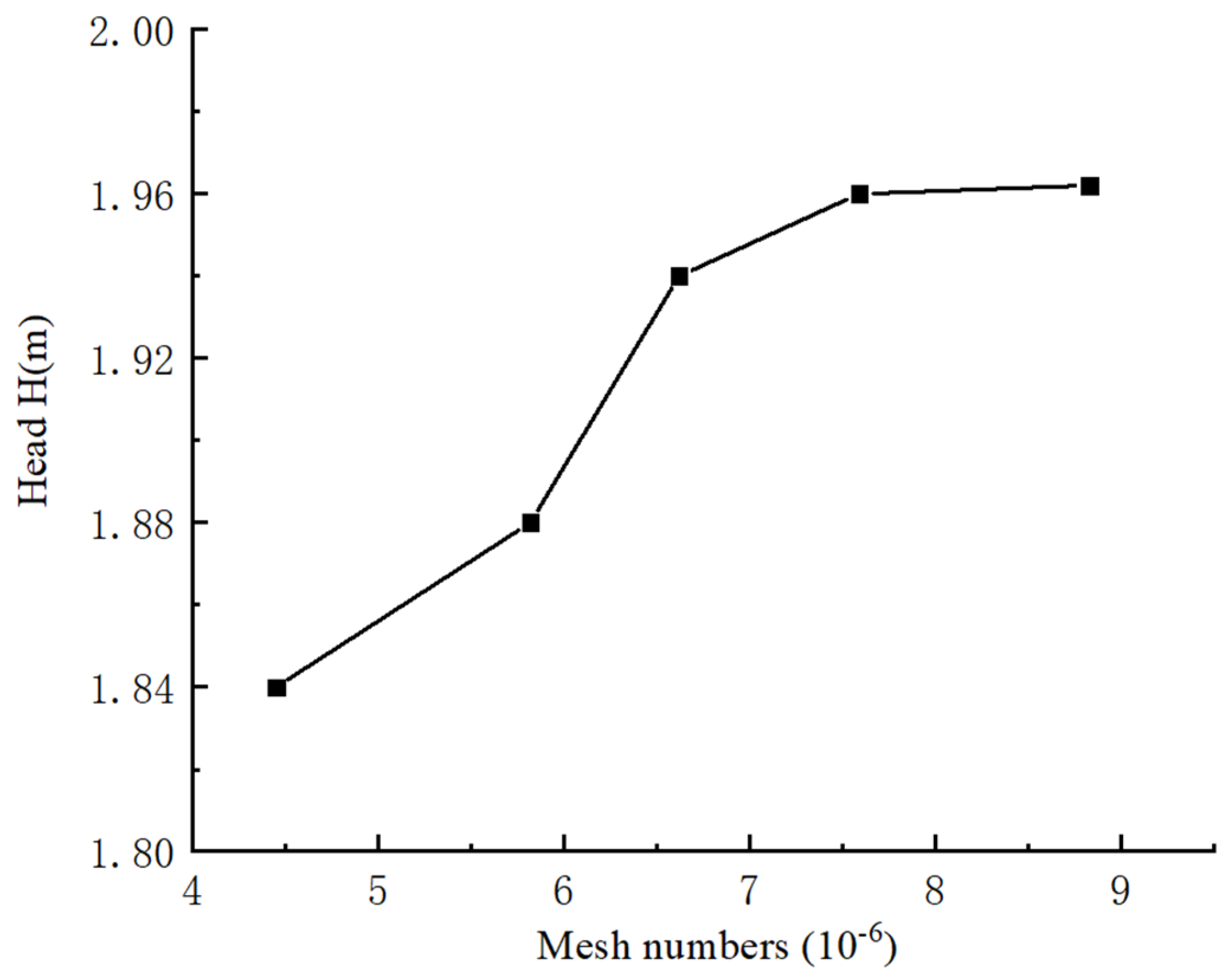
2.2. Meshing and Validation of Mesh Independence

Pointwise software (V18.3R1) was used to mesh the pump model. To improve the accuracy and efficiency of the numerical calculations, a mixture of meshes was used for the impeller and to guide the vane areas, and structured meshes were used for the inlet and outlet areas. Adjusting the number of nodes in the mesh control edges and encrypting the mesh in the impeller and guide vane areas make the computational mesh smoother and more uniform. The numerical simulation calculation meshes of the bidirectional axial pump are shown in Figure 2.
When performing the numerical calculation, the number of meshes in the computational domain had a large impact on the results and efficiency of the numerical calculations. In general, a smaller number of meshes resulted in a lower accuracy of the numerical calculations, and a larger number of meshes resulted in more accurate numerical calculations, but a larger number of meshes also required greater computational resources. The mesh independence was tested under design conditions, and the number of meshes was controlled by adjusting the number of nodes and the size of the mesh, while ensuring the quality of the mesh. Figure 3 shows the validation of the mesh independence, which was performed by adjusting the number of nodes of the mesh. The head of the pump device remained basically constant when the number of meshes was 7,599,359, which verified the mesh independence. The total number of computational domain meshes was 7,599,359, the impeller and guide vane meshes were unstructured meshes with numbers of 4,952,679 and 1,264,855, and the inlet and outlet were structured meshes with numbers of 665,606 and 716,219. The mesh quality was above 0.4.

2.3. Governing Equations and Turbulence Model

Bidirectional axial pump fluid flow in the flow field, its quality will neither be randomly generated nor disappearing; the fluid flow is a continuous medium and there is no void. Reflecting the continuity of this flow, the equation representing this phenomenon is referred to as the continuity equation [23].
Continuity equation:
ρ t + ρ μ x + ρ ν y + ρ ω z = 0
where ρ is the density of the fluid; μ, ν and ω are the components of the velocity vector U in the x, y and z directions, respectively; and t is time.
The related momentum equation is known as the governing equation. The momentum equation allows for a simpler study of the forces interacting between the fluid and the boundary in a flow field, requiring only that the local pressures and velocities to which the fluid is subjected be expressed as a function of force and momentum, which can be expressed as the following [24]:
ρ u i t + ρ u i u j x j = p x i + τ i j x j + S m i
where p is the static pressure; Smi is a customized source term for the momentum equation, including gravity, multiphase flow interactions, etc.; and τij is the stress tensor.
τ i j = μ u i x j + u j x i 2 3 μ u k x k δ i j
where μ is the dynamic viscosity and δij is the Kronecker sign, which is taken to be 1 when i = j and 0 otherwise.
The SST k–ω turbulence model can predict the flow characteristics of the shear layer part of the pump more accurately, so the SST k–ω turbulence model was chosen in this study, which can be expressed as follows [25].
ρ k t + ρ k u i x i = x j μ + μ t σ k k x j + G k + G b ρ ε + S k ρ ε t + ρ ε u i x i = x j μ + μ t σ ε ε x j + C 1 ε ε k G k + C 3 ε G b C 2 ε ρ ε 2 k + S k
where μ t = ρ a 1 k max a 1 ω , S F 2
P k = μ t u i x j + u j x i u i x j 2 3 u k x k 3 μ t u k x k + ρ k
where β * ρ k ω is the dissipative term of the k equation; P k is the turbulent synthesis term generated by the viscous force; and F1, F2 are the SST k–ω mixed functions, which are 1 near the wall and 0 at the shear layer.

2.4. Boundary Conditions

The commercial software CFX (v2020) was used for the numerical simulation of the bidirectional axial pump under different operating conditions. Table 2 shows the boundary conditions of the numerical simulation. The pump’s internal reference pressure was set to one standard atmospheric pressure. The impeller speed was set to 1450 r/min, and time needed to be taken as a variable in the analysis of the unsteady calculation. A 3° rotation of the impeller was chosen as a time step, i.e., 0.000344828 s, and the total computational time was 10 cycles of the impeller, which was a total of 3600°, i.e., 0.331034482 s, which could ensure the accuracy of the computational results.

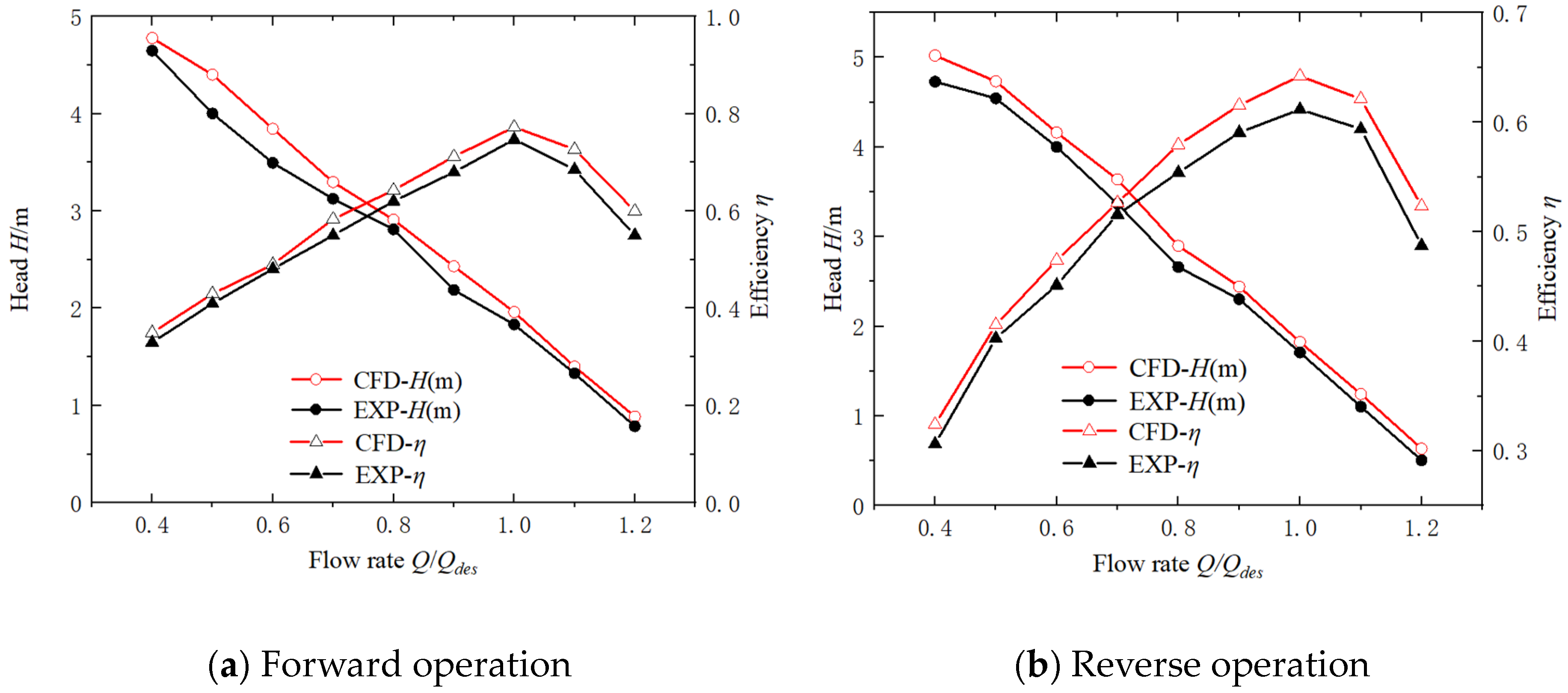
2.5. Physical Model Test Verification

The reliability of the numerical model was verified by testing the physical model to obtain the external characteristics of the bidirectional axial pump device and comparing them with the numerical calculation results [26]. The schematic of this experiment is shown in Figure 4. The main functional components include the bidirectional axial flow pump, motor, inlet and outlet pressure sensors, torque meter, date collector and electromagnetic flowmeter.

3. Results and Analysis

3.1. Comparative Analysis of the External Performance of the Bidirectional Axial Flow Pump

In the physical model test of the bidirectional axial flow pump, the head and efficiency curves were obtained for forward and reverse operations at a speed of 1450 r/min. The comparison between the model test results and numerical simulation values is shown in Figure 5. The trends of the head and efficiency of the model test and the numerical calculation results are consistent with each other, and the maximum error was within 5%, which ensured the accuracy of the numerical simulation.
A comparison of the external characteristics under optimal conditions of the forward and reverse rotations was then performed. Under optimal operating conditions, the head and efficiency for the reverse operation were 0.13 m and 13.1% lower than for the forward operation, respectively, which indicates that a bidirectional axial flow pump that utilizes an S-shaped hydrofoil design exhibits low efficiency and hydraulic instability when operated in reverse. It is also interesting to know how to improve its reverse performance to save energy and promote sustainability.

3.2. Analysis of the Internal Flow Field

Less energy loss in the passage of the fluid through which the guide vanes can be achieved by correctly designing the geometry and arrangement of the rear guide vanes. A guide vane’s shape and angle change the direction and velocity of fluid flow as it passes through the vane and directs the fluid to the next component in a manner more conducive to energy transfer. The presence or absence of a rear guide vane is a characteristic that distinguishes forward and reverse conditions. The full flow channel streamline of the pump device under different operation conditions was analyzed as in Figure 6. After the fluid was accelerated by the impeller rotation, the velocity at the rim was larger, the velocity at the hub was smaller, and there existed a region of lower flow velocity in the intermediate region, which led to turbulence of the flow streamline in the outlet area of the impeller. With the increase in flow rate, this phenomenon would be weakened. Through the reasonable design of the bidirectional axial flow pump’s front and rear, a guide vane was installed, and the guide vane recovery energy and the kinetic energy of the fluid was converted into pressure energy, so as to alleviate this phenomenon.

3.3. Unsteady Flow Characterization in the Impeller Area

Figure 7 shows that there are ten monitoring points on the blade surface, respectively, where numbers P1, P2 and P3 are the radial monitoring points of the impeller and P4, P2 and P5 are the circumferential monitoring points.
In this study, the pressure pulsation coefficient Cp [27] measured pressure pulsation in the bidirectional axial pump. The formula for Cp is the following:
C p = 2 ( p p ¯ ) ρ u 2 2
where   P ¯   is the pressure at the monitoring point, Pa; P ¯ is the average value of the pressure, Pa; u2 is the outlet speed of the impeller, m/s; and ρ is the density of the medium, kg/m3.
Figure 8a shows the time domain diagram of the impeller surface pressure pulsation for forward 1.0 Qdes conditions. In a cycle, the monitoring point of Cp at the impeller suction surface showed obvious peaks and valleys, and the change in Cp at the monitoring point of the impeller suction surface was more complicated during the forward operation. In the forward operation under the 1.0 Qdes operating condition, the monitoring points generated seven peaks and seven valleys in a cycle, and these peaks and valleys were the same number as the number of guide vanes. The Cp amplitude at the radial monitoring point was growing from the hub towards the tip of the blade with a significant gradient.
Figure 8a shows that in the reverse operation under the 1.0 Qdes operating condition, the monitoring points generated seven peaks and seven valleys in a cycle, and these peaks and valleys were the same number as the number of guide vanes. The Cp of the impeller was heavily influenced by the guide vanes. The tip clearance leakage may have led to pressure fluctuations at the blade top. Compared with the forward rotating condition, it is obvious that the Cp of the impeller became more regular on the suction surface. The Cp in hydraulic machinery is generated periodically over time, and the generation of pressure pulsations is often accompanied by noise and vibration, mechanical fatigue damage, and lower efficiency. The impeller inlet and top positions have a Cp amplitude that is larger, which may cause pump operation instability, low efficiency, noise and vibration, and damage at the inlet and the top of the impeller, which is consistent with the axial flow pump impeller’s usual damage location.
In this study, a fast Fourier transform (FFT) for converting time domain signals to frequency domain signals was employed. As shown in Figure 9a, the primary frequency of the pressure surface monitoring point was the pump’s rotational frequency (f/fn = 1), and the secondary primary frequency was the guide vane frequency (f/fn = 7). The primary frequency of the suction surface monitoring point was the pump’s rotational frequency, and the guide vane frequency also played a role, in addition to the multiple pump rotational frequency. Analyzing the primary frequency, the point of monitoring the largest amplitude of the primary frequency was P3′ at the rim, and the minimum amplitude of the primary frequency was monitored at P2′ at the middle position of the blade in the radial direction. The guide vane frequency decreased from the hub to the top of the blade. The amplitude of pulsation at the maximum monitoring point P5′ was 6–15 times greater than the Cp amplitude at the other four monitoring points. By comparing the Cp amplitude in the suction and pressure surfaces, the pressure surface had a higher amplitude of pulsation overall, except at the inlet monitoring point P4′.
As shown in Figure 9b, the primary frequency at hub monitoring point P1′ and inlet monitoring point P4′ was the guide vane frequency, and the primary frequency of the other monitoring points was the pump’s rotational frequency on the pressure surface. The Cp amplitude of the pump’s rotational frequency increased gradually from the hub to the top of the blade, while the rate of increase in the Cp amplitude was relatively large from the middle to the top of the blade. The guide vane frequency amplitude varied slightly. The primary frequency was the guide vane frequency, and the sub-primary frequencies were the blade passage frequency (BPF) and the pump rotation frequency. In addition, the primary frequency of Cp on the reverse suction surface changed from the shaft frequency of the forward operating condition to the guide vane rotation frequency.
For analyzing the transient force changes on the impeller under the calculated operating conditions, the radial force (FR) and axial force (FZ) were calculated under different operating conditions. Figure 10 and Figure 11 show the transient changes in FR and FZ on the impeller. In this paper, the direct integration method was used to solve the FR of the impeller with the following equations:
F x = P i sin φ cos θ d A
F y = P i sin φ sin θ d A
F = F x 2 + F y 2
where Fx, Fy are the radial force components on the x, y axes; Pi is the pressure of the nth grid node; φ is the angle between the pressure Pi of the grid node and the Z-axis; and θ is the angle between the projection of the pressure Pi of the grid node on the XOY plane and the X-axis.
Figure 10 shows the transient change in the FR of the impeller. Under the forward operating condition, the amplitude of the FR of the impeller decreased and then increased as the flow rate increased. Under the design flow rate condition, the FR amplitude of the impeller was minimum. The FR amplitude decreased as the flow rate under the reverse condition. Compared with the forward operating conditions, the FR amplitude of the impeller increased by 415.1%, 8.1% and 9.6% in the reverse under 0.8 Qdes, 1.0 Qdes and 1.2 Qdes conditions, respectively, indicating that the imbalance force in the radial direction of the impeller increased under the reverse operation condition.
Figure 11 shows the transient change in the FZ of the impeller. The FZ is strongly influenced by the variation in the flow rate. The average FZ ratio on the impeller was about 15:10:2, under forward conditions at flow rates of 0.8 Qdes, 1.0 Qdes and 1.2 Qdes, and about 13:9:4, for reverse conditions. Compared with the forward operating conditions, the amplitude FZ of the impeller increased by 4.3%, 8.4% and 129% under the reverse 0.8 Qdes, 1.0 Qdes and 1.2 Qdes conditions. The FZ and FR of the impeller under low flow conditions were large.

3.4. Analysis of Unsteady Flow in the Pump Device

The bidirectional axial flow pump device is characterized by a compact structure and a shorter distance between the impeller and the guide vane. As shown in Figure 12, nine monitoring points were set up within the pumping device to analyze its pressure pulsation characteristics.
As shown in Figure 13a, the Cp period correlated with the impeller rotation period. The largest average Cp amplitude was about 0.0056 in the impeller inlet area, which is due to the direct impact of the fluid on the blades. In the same cross-section, the Cp amplitude decreased as the monitoring point moved from the top of the blade to the hub, which was related to the blade design that was the distribution of loads along the blade spread. The points at the rim were the first to reach the peaks and valleys, the points at the middle position were the next to reach the peaks and valleys, and the points at the hub were the last to reach the peaks and valleys. This is because after the fluid was accelerated by the rotating impeller, the velocity was greater at the rim and less at the hub, and the fluid would flow through the rim area first and finally through the hub area. The Cp amplitude appeared to be the largest in the impeller inlet area, and the average Cp amplitude in the impeller inlet area was 2.7 and 23.6 times higher than those of the impeller outlet area and the guide vane outlet area, respectively. As shown in Figure 13b, the impeller rotated for one cycle, and the monitoring point produced four peaks and four valleys. As shown in Figure 13b, one cycle of impeller rotation produced four peaks and four troughs at the monitoring point, coinciding with the number of impellers. This was due to the impeller being a rotating part and the rotating pressure of the impeller alternately changing to produce, so there was a direct relationship between the number of peaks and valleys with the number of blades, while the number of guide vanes had a smaller impact on it. The Cp amplitude appeared to be the largest in the impeller inlet area, and the average Cp amplitude in the impeller inlet area was 19.2 and 5.7 times higher than those of the guide vane inlet area and impeller outlet area, respectively. In the same radial direction, the Cp amplitude at the monitoring point firstly increased and later decreased from the inlet area of the guide vane to the outlet area of the impeller.
As shown in Figure 14a, the impeller inlet and outlet areas had a primary frequency of the BPF, a sub-primary frequency of 2 times the BPF and a smaller Cp amplitude at other frequencies. The frequency domain fluctuations in the guide vane outlet area were large, and the primary frequency in the guide vane outlet area was 2 times the BPF, the sub-primary frequency was BPF and there were also more low frequencies with smaller amplitudes. This may have been due to pressure pulsations generated by the presence of vortices and unreasonable impacts in the guide vane area. From observing the primary frequencies at the monitoring points of the same cross-section, a gradual increase in the Cp amplitude was observed from the hub to the rim, with the smallest gradient in the variation in the Cp amplitude in the guide vane outlet. This may have been because the guide vane is a flow-guiding component in the pump device, providing rectification of the fluid flowing from the impeller and reducing pressure fluctuations in the guide vane outlet area. As shown in Figure 14b, the guide vane inlet’s areas X7 and X8 had a primary frequency of the BPF and a sub-primary frequency of 2 times the BPF, while X9 had a primary frequency of 2 times the BPF and a sub-primary frequency of the BPF. The BPF was the primary frequency for both the impeller inlet and outlet areas. The Cp amplitude at the guide vane and impeller inlet areas decreased from the top of the blade to the hub, while the Cp amplitude at the impeller outlet area first decreased and subsequently increased. The Cp amplitude at the same radial position first increased and subsequently decreased from the guide vane inlet area to the impeller outlet area. The water passed through the guide vanes before passing through the impeller when running in the reverse direction. In the impeller inlet area, the largest Cp amplitude was of about 0.011. A comparison of the Cp in the impeller inlet area with the forward operation was about twice as large as in the forward operation. This shows that when operating in the reverse direction, due to the shorter distance from the impeller to the guide vane, the water flow passed through the guide vane and then impacts the blades. The interference by the impeller and the guide vanes was also intense, resulting in drastic changes in the internal flow pattern.

4. Conclusions

Bidirectional axial flow pumps are characterized by a low efficiency and hydraulic instability in reverse. This study took the bidirectional axial flow pump as the research object and analyzed its unsteady flow characteristics by using an unsteady numerical simulation, the impeller surface and pump device pressure pulsation characteristics, and the impeller’s transient force changes. The following conclusions were made.
  • The bidirectional axial flow pump had different energy characteristics under the forward and reverse conditions. A flow turbulence occurred in the impeller outlet area during the reverse operation, which diminished as the flow rate increased.
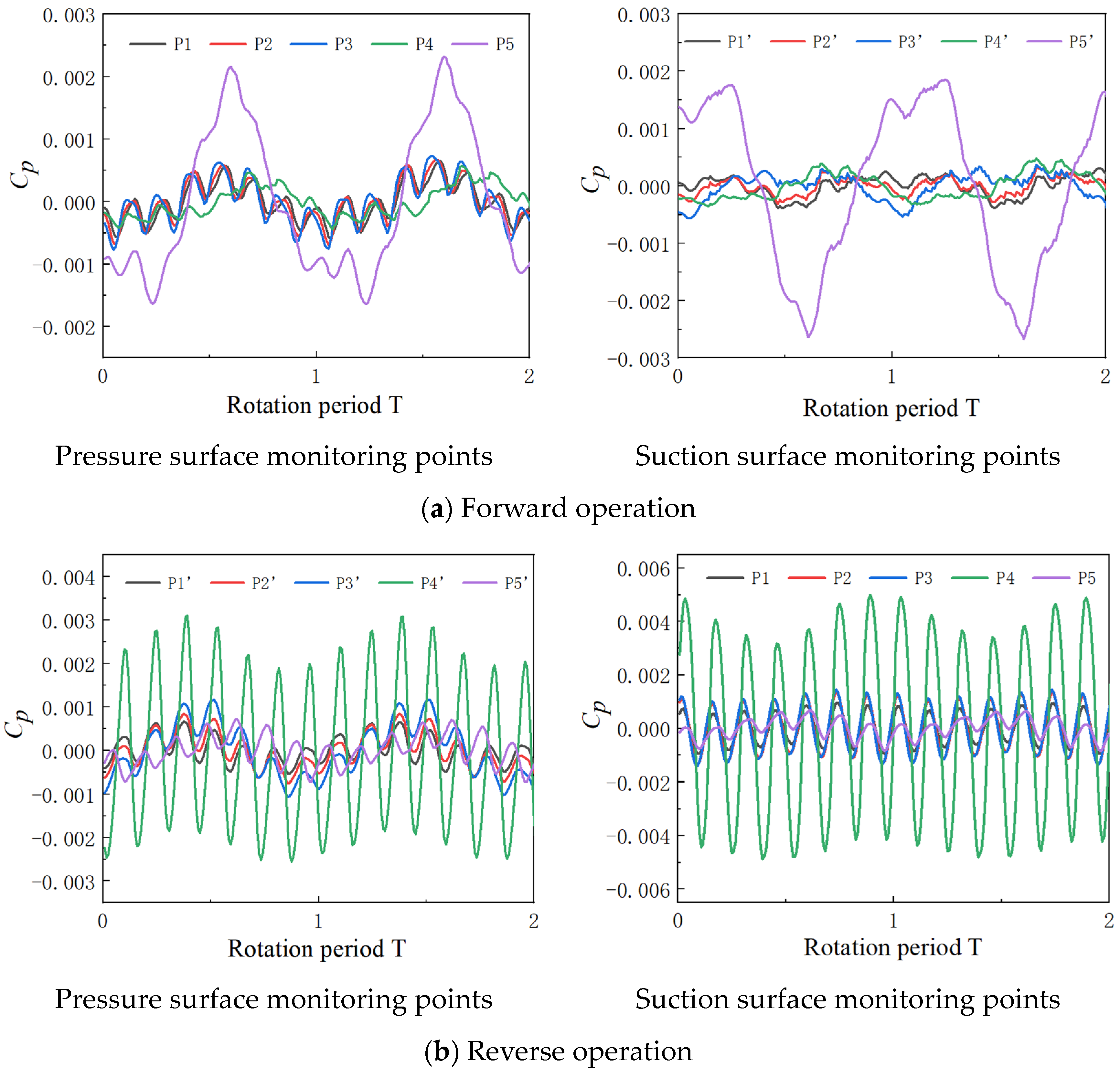
  • The largest Cp amplitudes in the circumferential and radial directions of the impeller surface were located at the inlet and at the tip of the blade, respectively, which corresponded to the location where the blade was usually damaged. When operating in reverse, the primary frequency of the Cp on the impeller suction surface became the guide vane frequency, which indicated that the suction surface of the impeller was greatly influenced by the front guide vane.
  • The FZ and FR of the impeller under low flow conditions were large, so operation under low flow conditions should be avoided as much as possible. The FR amplitude was minimized under the optimal condition. For the same flow conditions, the impeller’s FZ and FR amplitudes were greater in the reverse operation than in the forward operation.
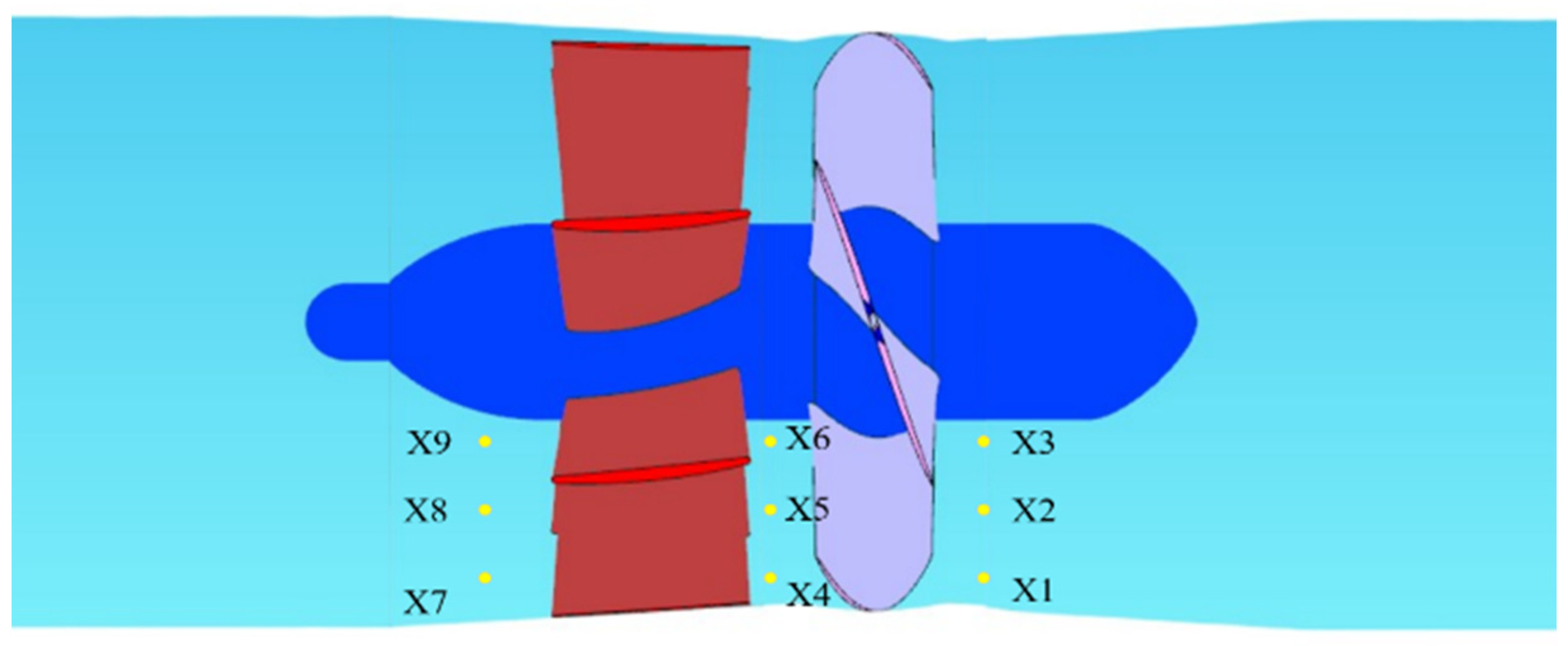
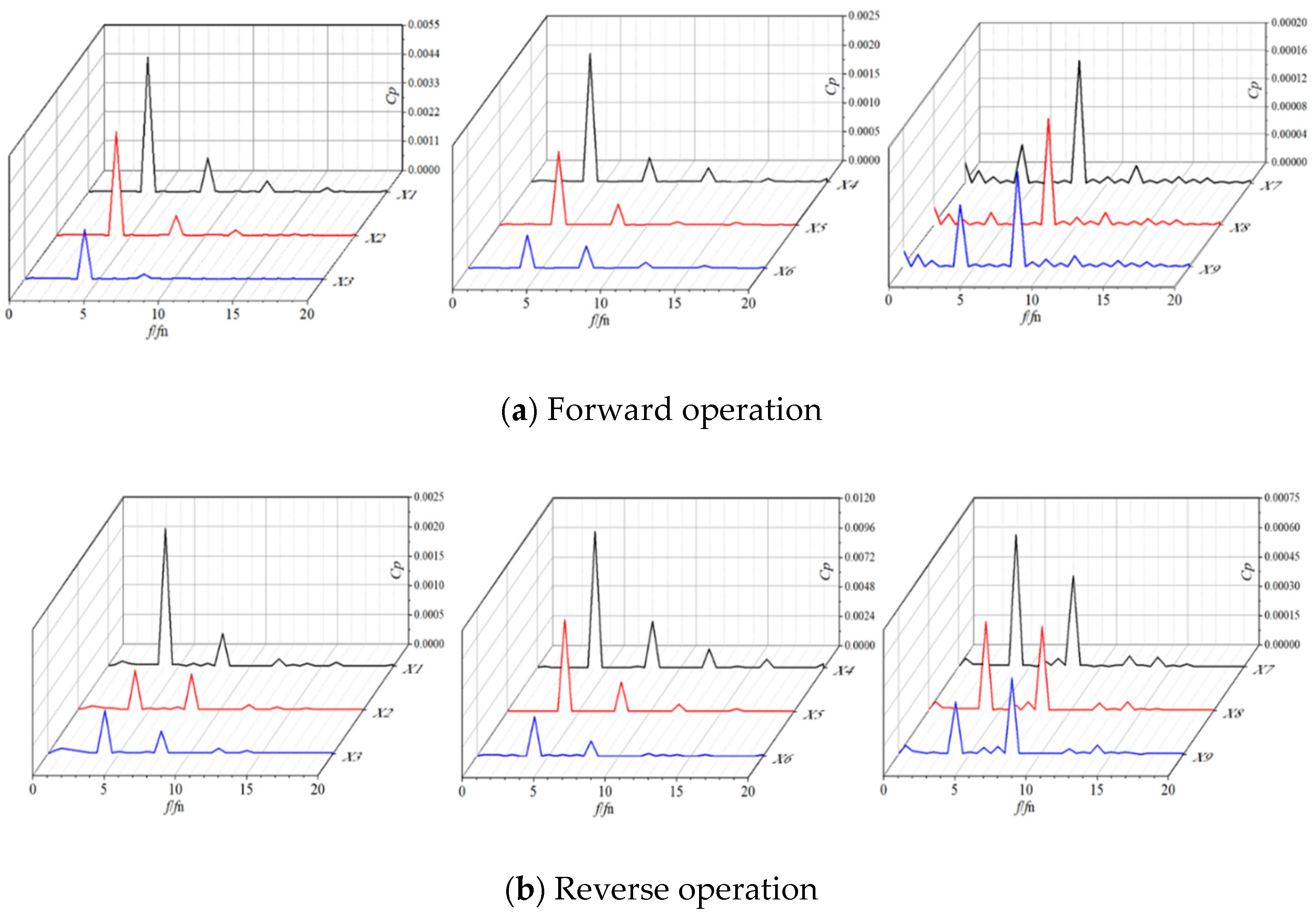
  • An analysis of the Cp characteristics of the pumping device under optimal conditions was carried out. Under the reverse operation condition, the impeller inlet area had the largest Cp amplitude, indicating that the dynamic and static interference were aggravated, which could be mitigated by a reasonable hydraulic design of the impeller and guide vane to improve their operational stability.
This paper analyzed the unsteady flow characteristics of bidirectional axial flow pumps, obtaining the Cp characteristics of the impeller surface and the pump device under forward and reverse operating conditions. This study may be a reference for subsequent improvement in the efficiency and stability of bidirectional axial flow pumps. Bidirectional axial flow pumps have the advantages of a high flow rate, high head, small spatial occupation and good bidirectional water suction performance, which contribute to the realization of the sustainability of the economy, society and environment.

Author Contributions

Methodology, W.S.; Validation, Y.D. and Y.Y.; Formal analysis, Z.X.; Investigation, Q.Z.; Data curation, Q.Z.; Writing—original draft, Y.D.; Writing—review & editing, Y.D.; Visualization, Z.X.; Supervision, Y.Y.; Project administration, W.S.; Funding acquisition, W.S. All authors have read and agreed to the published version of the manuscript.

Funding

This research was funded by the National Key Research and Development Project of China (No. 2019YFB 2005300), National High-Tech Ship Scientific Research Project of China (No. MIIT (2019) 360), National Natural Science Foundation of China (No. 51979138), National Natural Science Foundation of China (No. 273746), National Natural Science Foundation of China (No. 51979240), Jiangsu Natural Science Research Project (No. 19KJB470029), Natural Science Foundation of Jiangsu Province (No. BK20220609), Project funded by China Postdoctoral Science Foundation (No. 2022TQ0127) and Open Research Subject of Key Laboratory of Fluid Machinery and Engineering (Xihua University) of China (No. LTDL-2022001).

Institutional Review Board Statement

Not applicable.

Informed Consent Statement

Not applicable.

Data Availability Statement

The study did not report any data.

Conflicts of Interest

The authors declare no conflict of interest.

References

  1. Shi, L.; Zhang, W.; Jiao, H.; Tang, F.; Wang, L.; Sun, D.; Shi, W. Numerical simulation and experimental study on the comparison of the hydraulic characteristics of an axial-flow pump and a full tubular pump. Renew. Energy 2020, 153, 1455–1464. [Google Scholar] [CrossRef]
  2. Liu, C. Researches and developments of axial-flow pump system. Trans. Chin. Soc. Agric. Mach. 2015, 46, 49–59. [Google Scholar]
  3. Zhu, H.; Bo, G.; Zhou, Y.; Zhang, R.; Cheng, J. Pump selection and performance prediction for the technical innovation of an axial-flow pump station. Math. Probl. Eng. 2018, 2018, 6543109. [Google Scholar] [CrossRef]
  4. Xu, H. Research on the application of center-opening sectional bi-directional axial flow pumps in low head irrigation and drainage pumping stations. Drain. Irrig. Mach. 2000, 18, 20–23. (In Chinese) [Google Scholar]
  5. Li, L.; Wang, Z.; Hu, R.; Cen, M. Numerical Simulation of the Influence of Guide Vanes on Tubular Pumping Station Performance in Dual-directional Operation. Trans. Chin. Soc. Agric. Mach. 2007, 38, 76–79. (In Chinese) [Google Scholar]
  6. Zhang, R. Pump type and arrangement of low-lift two-way drainage and irrigation stations. Water Resour. Hydropower Eng. 1994, 36, 33–38. (In Chinese) [Google Scholar]
  7. Bozorgi, A.; Javidpour, E.; Riasi, A.; Nourbakhsh, A. Numerical and experimental study of using axial pump as turbine in pico hydropower plants. Renew. Energy 2013, 53, 258–264. [Google Scholar] [CrossRef]
  8. Liu, H.; Tang, F.; Yan, S.; Li, D. Experimental and numerical studies of cloud cavitation behavior around a reversible S-shaped hydrofoil. J. Mar. Sci. Eng. 2022, 10, 386. [Google Scholar] [CrossRef]
  9. Ma, P.F.; Wang, J.; Wang, H.F. Investigation of performances and flow characteristics of two bi-directional pumps with different airfoil blades. Sci. China Technol. Sci. 2018, 61, 1588–1599. [Google Scholar] [CrossRef]
  10. Liu, H.; Tang, F.; Shi, L.; Dai, L.; Shen, J.; Liu, J. The analysis of cavitation flow and pressure pulsation of bi-directional pump. J. Mar. Sci. Eng. 2023, 11, 268. [Google Scholar] [CrossRef]
  11. Chen, J.; Zhang, H.; Li, Y.; Meng, F.; Zheng, Y. Study on Inflow Distortion Mechanism and Energy Characteristics in Bidirectional Axial Flow Pumping Station. Machines 2022, 10, 1014. [Google Scholar] [CrossRef]
  12. Kan, K.; Xu, Z.; Chen, H.; Xu, H.; Zheng, Y.; Zhou, D.; Muhirwa, A.; Maxime, B. Energy loss mechanisms of transition from pump mode to turbine mode of an axial-flow pump under bidirectional conditions. Energy 2022, 257, 124630. [Google Scholar] [CrossRef]
  13. Liu, X.; Xu, F.; Cheng, L.; Pan, W.; Jiao, W. Stress Characteristics Analysis of Vertical Bi-Directional Flow Channel Axial Pump Blades Based on Fluid–Structure Coupling. Machines 2022, 10, 368. [Google Scholar] [CrossRef]
  14. Ma, P.; Wang, J. An analysis on the flow characteristics of bi-directional axial-flow pump under reverse operation. Proc. Inst. Mech. Eng. Part A J. Power Energy 2017, 231, 239–249. [Google Scholar] [CrossRef]
  15. Bai, L.; Zhou, L.; Han, C.; Zhu, Y.; Shi, W. Numerical study of pressure fluctuation and unsteady flow in a centrifugal pump. Processes 2019, 7, 354. [Google Scholar] [CrossRef]
  16. Yang, F.; Chang, P.; Jian, H.; Lv, Y.; Tang, F.; Jin, Y. Numerical analysis of unsteady internal flow characteristics of impeller-guide vane in a vertical axial flow pump device. Front. Energy Res. 2022, 10, 935888. [Google Scholar] [CrossRef]
  17. Wang, W.; Chen, Q.; Yan, D. Hydraulic stability analysis of a large prototype Francis turbine based on field test. J. Fluids Eng. 2018, 140, 114501. [Google Scholar] [CrossRef]
  18. Kang, C.; Mao, N.; Pan, C.; Zhou, Y. Turbulent flow characteristics in an axial-flow pump at direct and reverse modes. J. Appl. Sci. Eng. 2016, 19, 447–458. [Google Scholar]
  19. Zhang, X.; Tang, F.; Chen, Y.; Huang, C.; Chen, Y.; Wang, L.; Shi, L. Experimental study on the internal pressure pulsation characteristics of a bidirectional axial flow pump operating in forward and reverse directions. Machines 2022, 10, 167. [Google Scholar] [CrossRef]
  20. Kan, K.; Li, H.; Chen, H.; Xu, H.; Gong, Y.; Li, T.; Shen, L. Effects of clearance and operating conditions on tip leakage vortex-induced energy loss in an axial-flow pump using entropy production method. J. Fluids Eng. 2023, 145, 031201. [Google Scholar] [CrossRef]
  21. Guo, Y.; Yang, C.; Mo, Y.; Wang, Y.; Lv, T.; Zhao, S. Numerical study on the mechanism of fluid energy transfer in an axial flow pump impeller under the rotating coordinate system. Front. Energy Res. 2023, 10, 1106789. [Google Scholar] [CrossRef]
  22. Wu, D.; Bai, Y. Numerical Simulation of Flow-Induced Noise in Horizontal Axial Flow Pumps in Forward and Reverse Conditions. Water 2023, 15, 322. [Google Scholar] [CrossRef]
  23. Blazek, J. Computational Fluid Dynamics: Principles and Applications; Butterworth-Heinemann: Oxford, UK, 2015. [Google Scholar]
  24. Wilcox, D.C. Turbulence Modeling for CFD; DCW Industries: La Canada, CA, USA, 1998. [Google Scholar]
  25. Strelets, M. Detached eddy simulation of massively separated flows. In Proceedings of the 39th Aerospace Sciences Meeting and Exhibit, Reno, NV, USA, 8–11 January 2001; p. 879. [Google Scholar]
  26. Cui, B.; Liu, J.; Zhai, L.; Han, A. Analysis of the performance and pressure pulsation in a high-speed centrifugal pump with different hub-cutting angles. Mod. Phys. Lett. B 2023, 37, 2350117. [Google Scholar] [CrossRef]
  27. Bosioc, A.I.; Susan-Resiga, R.; Muntean, S.; Tanasa, C. Unsteady pressure analysis of a swirling flow with vortex rope and axial water injection in a discharge cone. J. Fluids Eng. 2012, 134, 081104. [Google Scholar] [CrossRef]
Figure 1. The hydraulic components and full flow channel model of the bidirectional axial flow pump.
Sustainability 16 00224 g001
Figure 2. Computational mesh.
Sustainability 16 00224 g002
Figure 3. Mesh independence validation.
Sustainability 16 00224 g003
Figure 4. Model pump test bench.
Sustainability 16 00224 g004
Figure 5. Comparison of external performance.
Sustainability 16 00224 g005
Figure 6. Comparison of streamlines under forward and reverse conditions.
Sustainability 16 00224 g006aSustainability 16 00224 g006b
Figure 7. Positions of monitoring points on the blade surface.
Sustainability 16 00224 g007
Figure 8. Time domain diagrams of impeller surface pressure pulsation for forward and reverse 1.0 Qdes conditions.
Sustainability 16 00224 g008
Figure 9. Frequency domain diagrams of impeller surface pressure pulsation for forward and reverse 1.0 Qdes conditions.
Sustainability 16 00224 g009
Figure 10. Transient changes in the radial force of the impeller under different flow conditions.
Sustainability 16 00224 g010
Figure 11. Transient changes in the axial force of the impeller under different flow conditions.
Sustainability 16 00224 g011
Figure 12. Positions of monitoring points in the pump device.
Sustainability 16 00224 g012
Figure 13. Time domain diagrams of the pressure pulsation for the forward and reverse operations of the pump.
Sustainability 16 00224 g013
Figure 14. Frequency domain diagrams of the pressure pulsation for the forward and reverse operations of the pump.
Sustainability 16 00224 g014
Table 1. Basic parameters of the bidirectional axial flow pump.
Main ParameterValue
Flow (m3/h)360
Head (m)1.96
Number of impeller blades, Zi4
Number of guide vane blades, Zs7
Rotational speed, n (r/min)1450
Impeller inlet diameter, D0 (mm)200
Inlet diameter, D1 (mm)200
Outlet diameter, D2 (mm)250
Table 2. Boundary condition settings.
LocationBoundary Conditions
Inlet of pump deviceFlow
Outlet of pump devicePressure
Fluid mediumWater
All physical surfaces of pumpNo-slip wall, Smooth wall
Interfaces on both sides of impeller in steady calculationFrozen Rotor
Interfaces on both sides of impeller in unsteady calculationTransient Rotor Stator
Other computing domain interfacesNone
Convergence accuracy10−4
Disclaimer/Publisher’s Note: The statements, opinions and data contained in all publications are solely those of the individual author(s) and contributor(s) and not of MDPI and/or the editor(s). MDPI and/or the editor(s) disclaim responsibility for any injury to people or property resulting from any ideas, methods, instructions or products referred to in the content.

