Article

Behavior of Horizontal-Directional Drilling for Multi-Pilot Heading Pretreating Blind Spots in Pipe Jacking Construction

1
No.3 Engineering Company Ltd. of CCCC First Harbor Engineering Company, Dalian 116011, China
2
School of Civil Engineering, Nanjing Forestry University, Nanjing 210037, China
*
Author to whom correspondence should be addressed.
Sustainability 2024, 16(1), 314; https://doi.org/10.3390/su16010314
Submission received: 5 December 2023 / Revised: 27 December 2023 / Accepted: 27 December 2023 / Published: 29 December 2023

Abstract

:
The application of non-excavation construction technology, such as the pipe jacking method, has obvious advantages in building urban underground space engineering projects, which can effectively reduce the occupation of ground surfaces and the migration of obstacles above or below the ground. However, pipe jacking machines with a rectangular cross-section can easily encounter great difficulty due to the significantly increased jacking resistance while it is jacked in hard rock strata, which are often influenced by large blind spots on the working face of pipe jacking machines with a rectangular cross-section. The aforementioned blind spots belong to areas that cannot be cut by the cutter heads due to the circular cutterhead and rectangular outer frame of pipe jacking machines with a rectangular cross-section. Therefore, the effective pretreatment of the aforementioned blind spots should be implemented prior to operating pipe jacking machines with a rectangular cross-section in hard rock strata. This paper presents a case study of employing horizontal-directional drilling as a multi-pilot heading pretreatment for breaking large blind spots on the working face of pipe jacking machines with a rectangular cross-section, which was implemented prior to operating a pipe jacking machine with a rectangular cross-section in shallow buried rock strata. In particular, this multi-pilot heading pretreatment is expected to be used to safely construct a rectangular comprehensive pipe gallery using pipe jacking machines with a rectangular cross-section in shallow buried rock strata and when passing underneath existing light rail lines, which can effectively save the precious land resources required for sustainable development. The study was implemented by employing a numerical simulation, focusing on the safety of the adjacent existing light rail line and the stability of the surrounding rocks, which are influenced by the variation in the distribution positions and sizes of the drilling holes used when implementing the horizontal-directional drilling. The results demonstrate that the horizontal-directional drilling applied for the multi-pilot heading pretreatment could effectively break the blind spots on the working face of the pipe jacking machine with a rectangular cross-section, in which the safety of the adjacent existing infrastructure was significantly influenced by the distribution positions and sizes of the drilling holes used when implementing the horizontal-directional drilling. This study can provide a reference for carrying out pipe jacking construction using pipe jacking machines with a rectangular cross-section, in which horizontal-directional drilling is employed as the multi-pilot heading pretreatment for breaking the large blind spots on the working face. Moreover, the distribution positions and sizes of the drilling holes used when implementing the horizontal-directional drilling could be appropriately optimized by utilizing the method of numerical analysis. Meanwhile, the study is also expected to eliminate the hazards of safely running the aforementioned adjacent existing light rail line during implementing the multi-pilot heading pretreatment of horizontal-directional drilling.

1. Introduction

The rapid urbanization process and constantly expanding urban population have brought many problems related to the sustainable utilization of resources, such as land resource scarcity and urban traffic congestion throughout the world [1,2], which has resulted in a sharp increase in the required utilization of urban underground space [3,4]. As a result, an unprecedented scale of underground space engineering construction has been implemented alongside the accelerated urbanization process in recent years [5]. However, the construction of underground engineering projects may encounter great difficulty such as complex geological and topographical conditions and adjacent existing infrastructure with smaller distances [6,7], and various construction technologies and equipment have been gradually developed for constructing underground engineering projects. Compared to traditional open-excavation technologies used for constructing underground engineering projects, the application of non-excavation construction technology has obvious advantages in building urban underground engineering projects, which can reduce the occupation of ground surfaces and the migration of obstacles above or below the ground [8]. Moreover, non-excavation construction technology can also reduce the impact on the safety of the surface traffic and surrounding buildings, protect the urban environment and accelerate engineering construction progress, and it can also promote the rational and standardized utilization of the urban underground space [9].
In the various non-excavation construction technologies, the pipe jacking method has been widely used in soft soil layers due to the rapid development of construction equipment and technology [8,9]. In particular, pipe jacking machines with a rectangular cross-section can fully utilize the cross-section of underground structures, which can thus effectively save urban underground space in the construction of urban underground engineering projects. Therefore, pipe jacking machines with a rectangular cross-section have obvious advantages compared to those with a circular cross-section when applied to underground engineering construction such as underground comprehensive pipe galleries and underground passages. In addition, the requirements of employing pipe jacking machines with a rectangular cross-section to construct underground spaces in complex urban environments have also sharply increased due to the rapid development of the urbanization process [10].
However, pipe jacking machines with a rectangular cross-section can easily encounter great difficulty due to the significantly increased jacking resistance while it is jacked in hard rock strata, which are often influenced by large blind spots on the working face of pipe jacking machines with a rectangular cross-section. Figure 1 shows a sketch map of the blind spots distributed on the working face of a pipe jacking machine with a rectangular cross-section, which belong to areas that cannot be cut by the cutter heads due to using a circular cutterhead and due to the rectangular outer frame of the pipe jacking machine with a rectangular cross-section. Therefore, the effective pretreatment of the aforementioned blind spots should be implemented prior to operating pipe jacking machines with a rectangular cross-section in hard rock strata. In view of the related studies in recent years, many studies have focused on the performance of the pilot heading pretreatment in building underground engineering projects, in which the adverse environment of the construction site can easily induce damage in the underground engineering project [11]. Compared with other methods, horizontal-directional drilling is an important and effective trenchless technology for the pilot heading pretreatment, since it can drill the pilot hole along the planned path with minimal influence on the surrounding rocks and adjacent infrastructures, in which the originally drilled pilot hole is enlarged using the reamers with varying diameters [12,13]. Therefore, horizontal-directional drilling has obvious advantage in implementing the pilot heading pretreatment, which is often adopted in the construction of underground engineering projects [14]. As a result, it can be seen that there have been many studies related to horizontal-directional drilling employed for multi-pilot heading pretreatment, which provides a chance for effectively pretreating the large blind spots on the working face of pipe jacking machines with a rectangular cross-section operating in hard rock strata.
In recent years, many studies have focused on the behavior of existing infrastructure being influenced by tunneling, as carried out by theoretical analysis, field monitoring and numerical simulations [15,16,17], the effectiveness of which have been confirmed in practical applications in underground engineering projects [18,19]. However, there have seldom been studies related to the construction of underground engineering projects using pipe jacking machines with a rectangular cross-section in hard rock strata, and further studies are required.
This paper presents a case study of a numerical investigation into the behavior of horizontal-directional drilling employed for the multi-pilot heading pretreatment of the blind spots on the working face of a pipe jacking machine with a rectangular cross-section, which was implemented prior to operating the pipe jacking machine with a rectangular cross-section in shallow buried rock strata. In particular, this multi-pilot heading pretreatment is expected to safely construct a rectangular comprehensive pipe gallery using a pipe jacking machine with a rectangular cross-section in shallow buried rock strata whilst passing underneath an existing light rail line, which can effectively save the precious land resources required for sustainable development. This study was implemented by employing numerical simulations, focusing on the safety of the adjacent existing light rail line and the stability of the surrounding rocks, as influenced by the variation in the distribution positions and sizes of the drilling holes when implementing horizontal-directional drilling. In the case study, the horizontal-directional drilling employed as the multi-pilot heading pretreatment has the advantages of not only breaking the aforementioned blind spots of the working face but also releasing the stresses of the surrounding rocks in the complex geological conditions and construction environment. The study is also expected to eliminate the safety hazards of the adjacent existing light rail line during implementing the aforementioned multi-pilot heading pretreatment.

2. Engineering Background

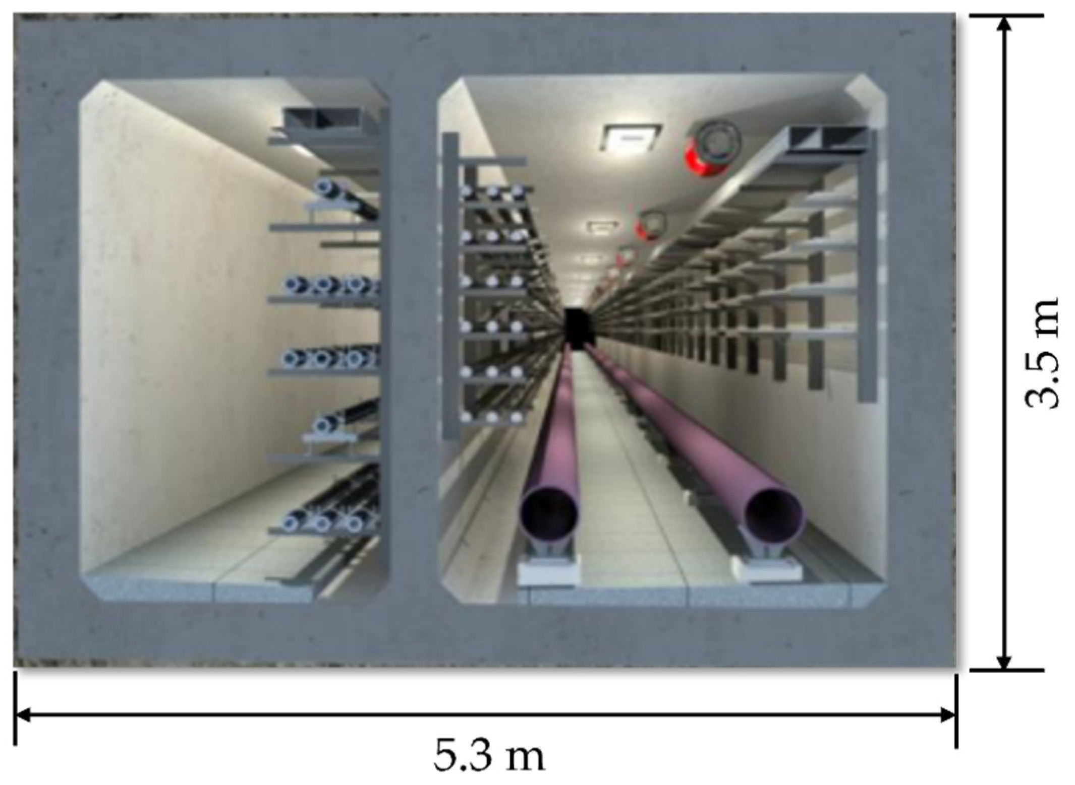
2.1. Engineering Profile

Figure 2 demonstrates the comprehensive pipe gallery passing underneath the adjacent existing light rail line, in which the pipe jacking method was adopted to build the comprehensive pipe gallery project in Wuhan city, and the buried depth of the comprehensive pipe gallery is about 5.3 m. According to geological surveying in the field, the buried strata around the comprehensive pipe gallery comprise plain soil, clay, moderately weathered mudstone and sandstone, strongly weathered mudstone and moderately weathered mudstone. The pipe jacking mainly passes through the aforementioned uniform moderately weathered mudstone layer, in which the compressive strengths of the rocks range from 28.5 MPa to 6 MPa. In terms of the hydrological situation, bedrock fissure water mainly exists in the underlying bedrock fissures, and it mainly receives lateral recharging from groundwater, in which the water volume is generally not large and has little impact on the pipe jacking process. Moreover, the ground surface water has little impact on the comprehensive pipe gallery project.
Figure 3 shows the standard internal cross-sectional size of the comprehensive pipe gallery, in which a reinforced concrete pipe with a rectangular cross-section is jacked with a 42 m length, and the standard internal size of the jacked reinforced concrete pipe is 5.3 m × 3.5 m.

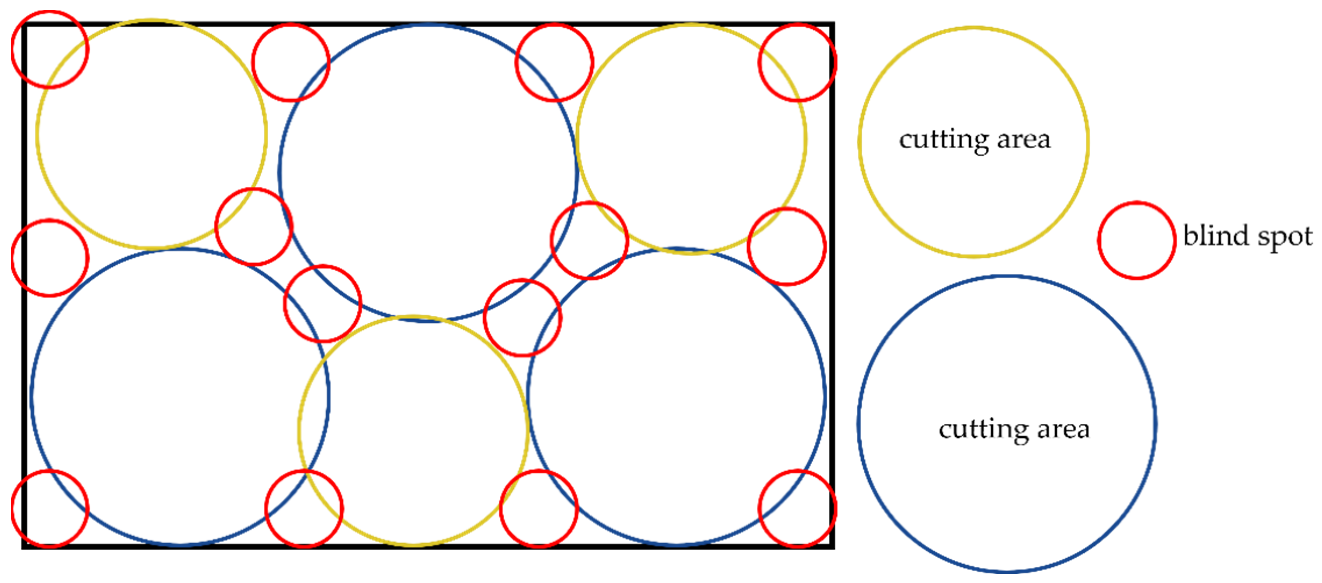
2.2. Multi-Pilot Heading Pretreatment

The comprehensive pipe gallery project was built within the shallow buried rock strata and constructed using the pipe jacking method, whereas traditional pipe jacking machines with a rectangular cross-section have difficulty in jacking the aforementioned rectangular reinforced concrete pipe in shallow buried rock strata. Therefore, the multi-pilot heading pretreatment was employed for effectively pretreating the blind spots on the working face of the pipe jacking machine with a rectangular cross-section and releasing the stresses of the shallow buried rock strata, which was implemented prior to operating the pipe jacking machine with a rectangular cross-section in the hard rock strata. As demonstrated in the aforementioned Figure 1, the blind spots belonged to the areas that could not be cut by the cutter heads in the pipe jacking machine with a rectangular cross-section. Moreover, the blind spots were mainly distributed between the cutter heads and around the outer boundary of the pipe jacking machine with a rectangular cross-section, which were disposed of by the multi-pilot heading pretreatment using horizontal-directional drilling, and the distribution of the drilling holes was as close as possible to the outer boundary of the jacking area to ensure a more effective processing area.

3. Proposal of the Numerical Model for the Pilot Heading Pretreatment Using Horizontal-Directional Drilling

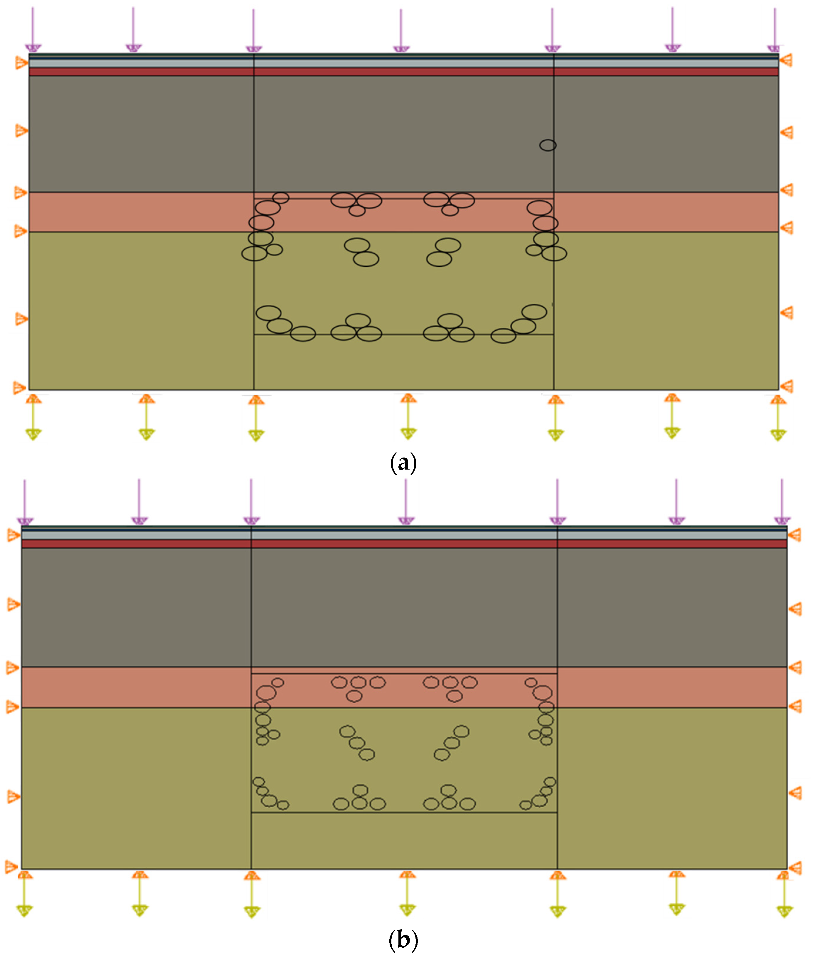
3.1. Numerical Model

Figure 4 shows the numerical model of the pilot heading pretreatment using horizontal-directional drilling that was implemented underneath the adjacent existing light rail line, which was simulated for numerically investigating the safety of the adjacent existing light rail and the stability of the surrounding rocks. Moreover, the required threshold value of safely running the existing light rail line was less than 10 mm, and the ground surface settlement should thus be controlled, which may be influenced by variations in the distribution positions and sizes of the drilling holes when implementing horizontal-directional drilling. Therefore, two cases of horizontal-directional drilling employed as the multi-pilot heading pretreatment were studied in the numerical simulation, as shown in Figure 4, which were expected to control the ground surface settlement by adjusting the distribution position and sizes of the holes when implementing the horizontal-directional drilling technology. In cases 1 and 2, the implementations of horizontal-directional drilling had varied distribution positions and sizes of the drilling holes, in which the drilled holes had three diameters of 0.3 m, 0.4 m and 0.5 m.
The size of the numerical model was 20 m long and 9.4 m high, in which the pretreatment range of the pilot heading was 7.7 m long and 4.5 m high. The assumptions of the boundary conditions were employed in the numerical model, in which the lateral sides were restricted in the horizontal direction, the bottom was constrained in both the horizontal and vertical directions and the upper boundary was free in all directions. Moreover, the loads from light rail track and road traffic were generally 20 kPa and 5 kPa, respectively. Therefore, an equivalent linear superposition load of 25 kPa was applied to the ground surface directly below the light rail line, and an equivalent linear load of 5 kPa was applied to the ground surface below the traffic roads, which were on both sides of the light rail track.
As mentioned above, the distribution of the drilling holes should be as close as possible to the outer boundary of the jacking area to ensure a more effective processing area, and small rotating heads should be adopted in the processes of drilling the holes, which are also expected to improve the processing area by adjusting the drilling holes.

3.2. Material Properties

The strata in the numerical model were divided into six layers according to the engineering survey, in which every layer was set as horizontal with homogeneous material properties in the layer. Moreover, the Mohr–Coulomb criterion was adopted for the numerical analysis [20,21], and Table 1 shows the specific parameters of the material properties for the strata.

3.3. Model Mesh

The mesh shape and size have an influence on the calculation results when using finite element simulations, in which denser grids with a smaller mesh size can obtain more accurate numerical results, although denser grids may lower the computational efficiency. In order to determine the appropriate mesh size for ensuring the calculation accuracy, element sizes of 0.3 m, 0.2 m, 0.1 m, 0.05 m and 0.03 m were selected, respectively, in the numerical simulation, considering the minimum diameter of drilling a hole was 0.3 m. The results demonstrate that the settlements of the ground surface were monotonically decreased and basically converged until the element size was 0.1 m. As a result, the coarse element size of 0.3 m was globally adopted in the numerical model, and the fine element size of 0.1 m was employed in the rectangular area implemented with the horizontal-directional drilling in the numerical model.

3.4. State of the Initial Stress and Displacement Fields

In the numerical analysis, the numerical initial stress field is the basis for the subsequent iterative calculations, in which a numerical initial stress field consistent with the field one can ensure the calculation accuracy of the subsequent numerical results. In the absence of overloading, the initial stress field of the strata is usually the self-weight stress field of the strata. Therefore, the first step in the numerical simulation is to balance the initial geostress field, which was of great significance for the numerical analysis of the pilot heading pretreatment using horizontal-directional drilling. Moreover, the natural strata have generally already reached their steady states due to the effect of long-term consolidation, and the redistribution of the displacement field caused by the pilot heading pretreatment can thus be regarded as a secondary displacement field, which is the displacement change in the numerical simulation.
As described above, the first requirement in the numerical calculation was to balance the geostress field, in which the overall stress and strain under the balance of gravity field could serve as the initial stress state of the numerical model. Figure 5 shows the numerically obtained stress and vertical displacement of the surrounding rocks after the geostress equilibrium. It can be clearly seen that the average shear stress value in the numerical geostress field was very small, and the vertical settlement of the strata was below 0.001 mm, which meets the requirements of the geostress equilibrium in the numerical analysis.

4. Numerical Investigation into the Behavior of Surrounding Rocks with Varied Distribution Positions and Sizes of Drilling Holes in Horizontal-Directional Drilling

The action of horizontal-directional drilling in surrounding rocks is constrained and influenced by the underground environment of the surrounding rocks. At the same time, the action of horizontal-directional drilling inevitably causes disturbances to the surrounding rocks. Therefore, the variation in the behavior of the surrounding rocks due to the multi-pilot heading pretreatment with varied distribution positions and sizes of the drilling holes in the horizontal-directional drilling was studied herein.

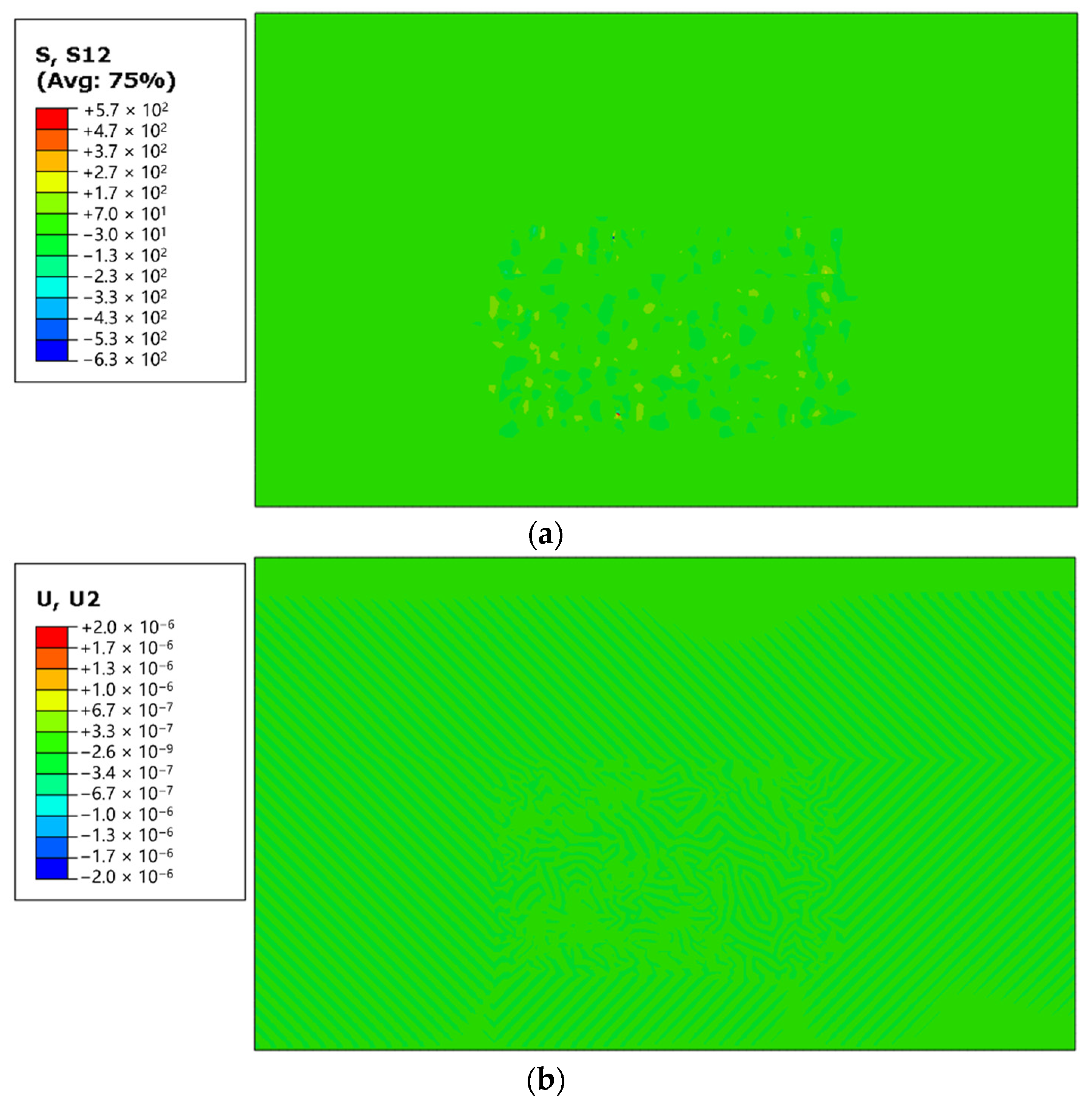
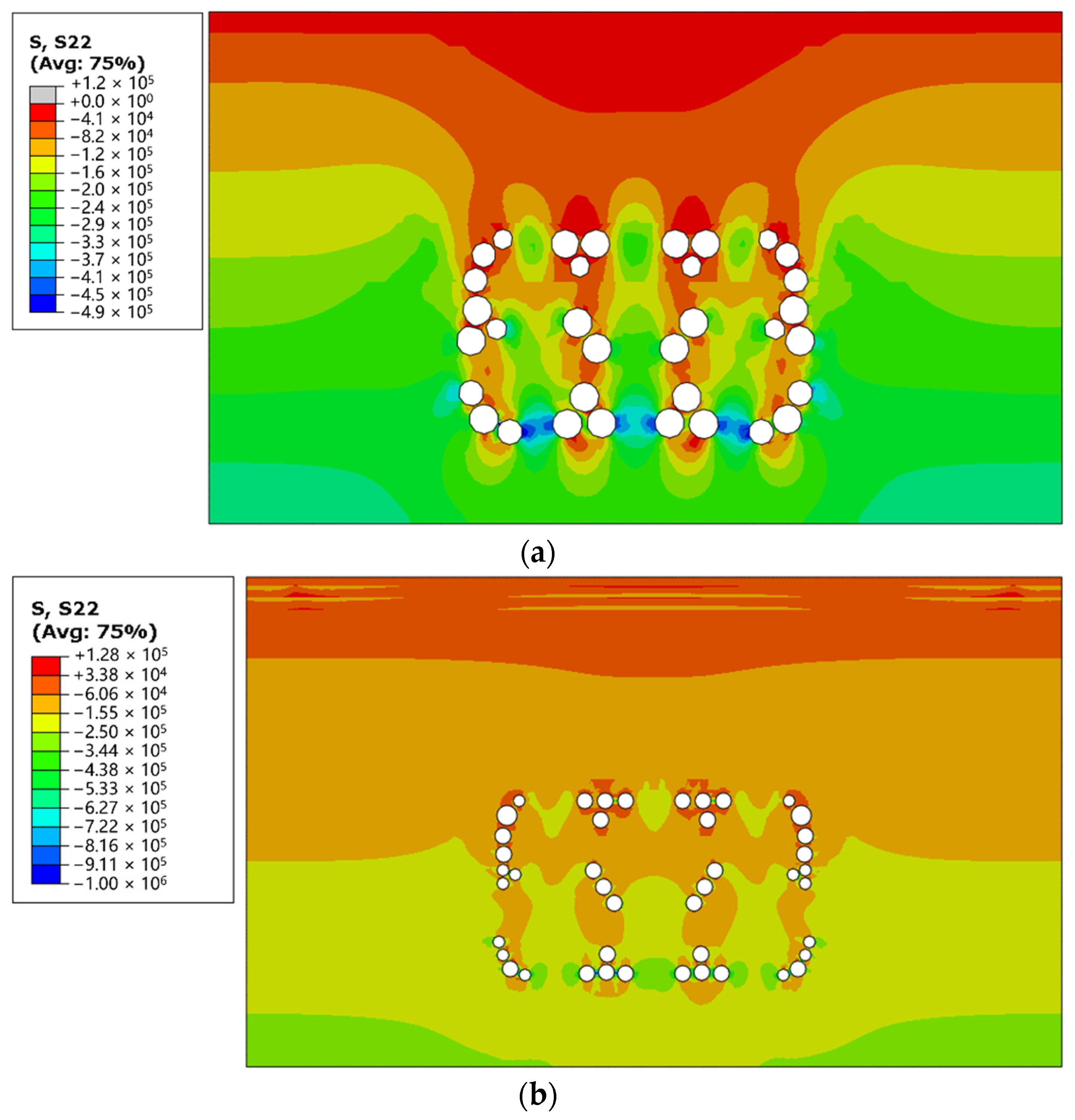
4.1. Stress Redistribution of Surrounding Rocks

Figure 6 shows the stress redistributions of the surrounding rocks after implementing the horizontal-directional drilling as the multi-pilot heading pretreatment in cases 1 and 2. It can be obviously seen that the multi-pilot heading pretreatment using horizontal-directional drilling caused the release and redistribution of stresses in the surrounding rocks. In the area around the drilling location, the stress field near the upper hole was weakened, whereas that near the lower hole was enhanced due to the uplift effect of the surrounding rocks. The maximum principal stresses of the surrounding rocks in cases 1 and 2 occurred in the strongly and moderately weathered rock layers. Moreover, the maximum principal stresses of the surrounding rocks in cases 1 were all below 0.5 MPa, and those in case 2 were all below 1.0 MPa, which were less than the measured compressive strengths of strongly and moderately weathered rock that ranged from 10 MPa to 18 MPa. This implies that the collapse of surrounding rocks should not occur during implementing the pilot heading pretreatment using horizontal-directional drilling.

4.2. Vertical Displacement of Surrounding Rocks

Figure 7 shows the vertical displacements of the surrounding rocks in cases 1 and 2. It is clear that the maximum vertical displacement of the ground surface in case 1 was about 13.1 mm, as shown in Figure 7a, which was larger than the threshold values of 10 mm for safely running the existing light rail line. Moreover, the maximum vertical displacement of the ground surface in case 2 was just 7.2 mm, as illustrated in Figure 7b, which met the required threshold values of 10 mm for safely running the existing light rail line. Therefore, horizontal-directional drilling with the distribution positions and sizes of the drilling holes in case 2 can be recommended for implementing the multi-pilot heading pretreatment in the field, which was expected for implementing the multi-pilot heading pretreatment whilst safely running the existing light rail line.

5. Verification by Practical Implementation

5.1. Numerical Model Validation

The aforementioned implementation of horizontal-directional drilling in case 2 was practically employed in the multi-pilot heading pretreatment. To verify the reliability of the adopted numerical model, the numerically calculated vertical displacement of the ground surface was selected for comparison with that obtained from field measurements. The numerically obtained and field-measured vertical displacements of the ground surface were about 7.2 mm and 8.1 mm respectively, in which there was only an error of 11% between the numerically calculated and field-measured ones, and both the numerical and field-monitored vertical displacements of the ground surface were less than the threshold values of 10 mm for safely running the existing light rail line. This reflects the feasibility and accuracy of the adopted numerical model for optimizing the distribution positions and sizes of the drilling holes in implementing horizontal-directional drilling for the multi-pilot heading pretreatment employed in the pipe jacking construction.

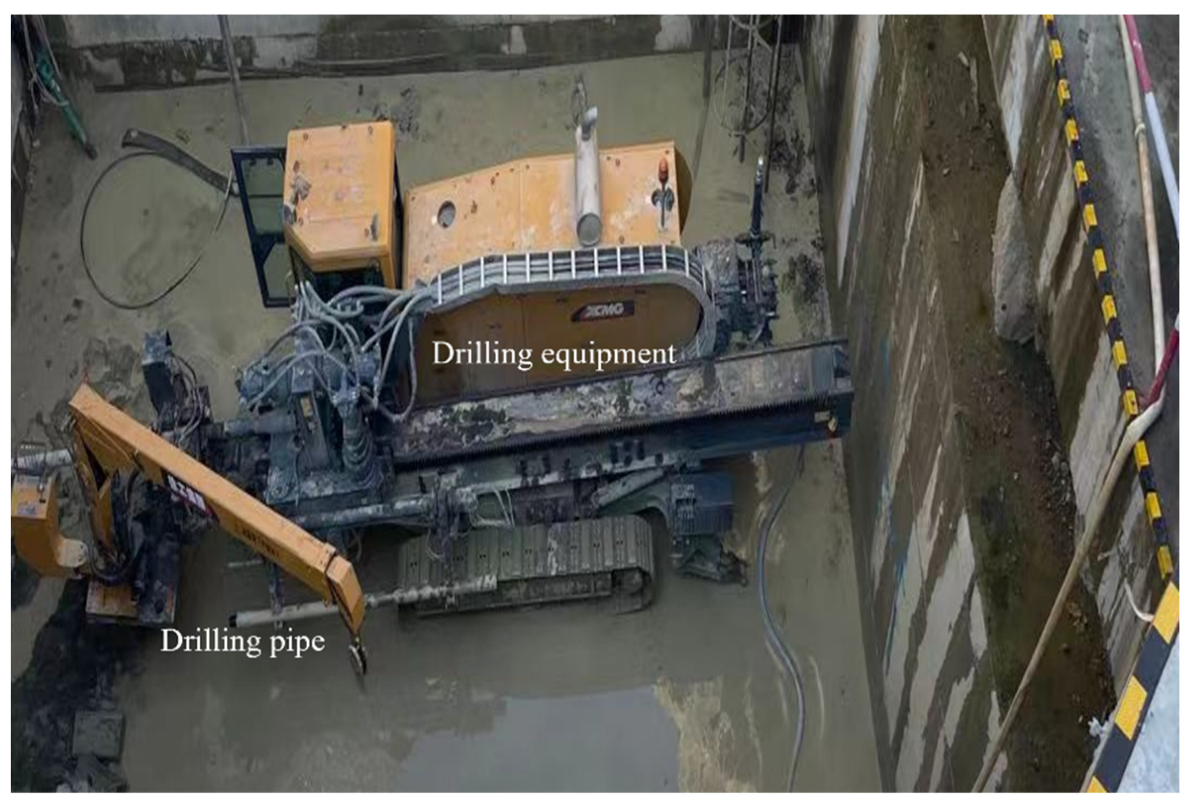
5.2. Implementation of Horizontal-Directional Drilling

The multi-pilot heading pretreatment was implemented using horizontal-directional drilling, as shown in Figure 8, which was performed prior to operating the pipe jacking machine with a rectangular cross-section in the shallow buried rock strata. In the horizontal-directional drilling, small rotating heads were adopted in the processes of drilling the holes, which were also expected to improve the processing area by adjusting the drilling holes. Moreover, the formed holes were filled with high-density loess in a timely manner using a high-pressure pump after completing the drilling, and the hole ends were sealed with a dedicated airbag to prevent the collapse of the construction site.

6. Conclusions

This paper presents a case study of employing horizontal-directional drilling as a multi-pilot heading pretreatment for breaking the large blind spots on the working face of a pipe jacking machine with a rectangular cross-section operating in shallow buried rock strata, which was adopted to construct a comprehensive pipe gallery passing underneath an existing light rail line. The study was implemented by employing a numerical simulation, focusing on the safety of the adjacent existing light rail line and the stability of the influence of the surrounding rocks due to the variations in the distribution positions and sizes of the drilling holes when implementing the horizontal-directional drilling, and the following conclusions were drawn.
(1)
The horizontal-directional drilling employed for the multi-pilot heading pretreatment could effectively break the blind spots on the working face of the pipe jacking machine with a rectangular cross-section, which was implemented prior to operating the pipe jacking machine with a rectangular cross-section in the shallow buried rock strata. Moreover, the implementation of the horizontal-directional drilling could also significantly release the stresses of the surrounding rocks from the initial ones in advance.
(2)
The distribution positions and sizes of the drilling holes when implementing the horizontal-directional drilling had a significant influence on the safety of the adjacent infrastructure and stability of the surrounding rocks. Therefore, the aforementioned distribution positions and sizes of the drilling holes should be appropriately optimized and designed for the multi-pilot heading pretreatment in pipe jacking construction when using a pipe jacking machine with a rectangular cross-section whilst working in shallow buried rock strata.
(3)
The numerical analysis could be employed to determine the distribution positions and sizes of the drilling holes when implementing horizontal-directional drilling applied for a multi-pilot heading pretreatment in pipe jacking construction using a pipe jacking machine with a rectangular cross-section whilst working in shallow buried rock strata, the effectiveness of which was confirmed in this case study.
(4)
The horizontal-directional drilling employed for the multi-pilot heading pretreatment in this case study can provide useful references for safely constructing rectangular comprehensive pipe galleries adjacent to existing infrastructure in shallow buried rock strata, in which a pipe jacking machine with a rectangular cross-section can be adopted for constructing the rectangular comprehensive pipe gallery, and the aforementioned multi-pilot heading pretreatment using horizontal-directional drilling can be implemented prior to operating the pipe jacking machine with a rectangular cross-section in shallow buried rock strata.

Author Contributions

Conceptualization, B.X., R.Y., H.D., Z.D. and Y.Z.; validation, B.X. and Y.Z.; investigation, B.X., R.Y., H.D., Z.D. and Y.Z.; data curation, H.D. and Z.D.; writing—original draft preparation, B.X. and R.Y.; writing—review and editing, Y.Z.; funding acquisition, Y.Z. All authors have read and agreed to the published version of the manuscript.

Funding

This research was funded by the Natural Science Foundation of Jiangsu Province (no. BK20211281), Six Talent Peak Projects.

Institutional Review Board Statement

Not applicable.

Informed Consent Statement

Not applicable.

Data Availability Statement

The data used to support the findings of this study are available from the corresponding author upon request.

Conflicts of Interest

The authors Binbin Xu, Runlai Yang, Hao Dai and Zhichao Dong were employed by the company CCCC First Harbor Engineering. The remaining authors declare that the research was conducted in the absence of any commercial or financial relationships that could be construed as a potential conflict of interest.

References

  1. Deng, R.F.; Ding, X.; Wang, J.L. Landscape ecological risk assessment and spatial pattern evolution analysis of the Central Yunnan Urban Agglomeration from 1995 to 2020 based on land use/cover change. Sustainability 2023, 15, 16641. [Google Scholar] [CrossRef]
  2. Zhang, W.H.; Song, Y.J.; Zhou, G.; Song, Z.W.; Xi, C. Multiobjective-based decision-making for the optimization of an urban passenger traffic system structure. Sustainability 2023, 15, 13644. [Google Scholar] [CrossRef]
  3. Zhang, P.; Feng, X.; Zeng, C.; Ariaratnam, S.T. Field performance of steel pipes during curve jacking in Gongbei tunnel. Tunn. Undergr. Space Technol. 2022, 128, 104585. [Google Scholar] [CrossRef]
  4. Chang, C.T.; Wang, M.J. Repair of displaced shield tunnel of the Taipei rapid transit system. Tunneling Undergr. Space Technol. 2001, 16, 163–173. [Google Scholar] [CrossRef]
  5. Tao, L.J.; Zhang, Y.; Zhao, X.; Bian, J.; Chen, X.H.; An, S.; Han, X.C. Group effect of pipe jacking in silty sand. J. Geotech. Geoenviron. Eng. 2021, 147, 05021012. [Google Scholar] [CrossRef]
  6. Wang, J.; Wang, P.C.; Wang, W.D.; Zhou, S.Q.; Fang, X. Optimization analysis of deformation of underlying tunnel in dewatering and excavation of phreatic aquifer. Adv. Mater. Sci. Eng. 2019, 2019, 2461817. [Google Scholar] [CrossRef]
  7. Singh, T.N.; Sazid, M. Simulation of old surface and underground working for assessment of slope stability. In Proceedings of the International Geomechanics Symposium, Al Khobar, Saudi Arabia, 30 October–2 November 2023. [Google Scholar]
  8. Ma, M.L.; Han, L.; Wu, Y.H.; Li, Q.Y.; Zhang, Y.X. Behavior investigation of three parallel large-size reinforced concrete circular pipes with the construction of pipe jacking. Appl. Sci. 2023, 13, 8901. [Google Scholar] [CrossRef]
  9. Ye, Y.C.; Peng, L.M.; Zhou, Y. Prediction of friction resistance for slurry pipe jacking. Appl. Sci. 2020, 10, 207. [Google Scholar] [CrossRef]
  10. Wen, K.; Shimada, H.; Zeng, W.; Sasaoka, T.; Qian, D.Y. Frictional analysis of pipe-slurry-soil interaction and jacking force prediction of pipe jacking. Eur. J. Environ. Civ. Eng. 2020, 24, 814–832. [Google Scholar] [CrossRef]
  11. Lueke, J.S.; Ariaratnam, S.T. Surface heave mechanisms in horizontal directional drilling. J. Constr. Eng. Manag. 2005, 131, 540–547. [Google Scholar] [CrossRef]
  12. Shu, B.; Ma, B.S. The return of drilling fluid large diameter horizontal directional drilling boreholes. Tunn. Undergr. Space Technol. 2016, 52, 1–11. [Google Scholar] [CrossRef]
  13. Yan, X.F.; Ariaratnam, S.T.; Dong, S.; Zeng, C. Horizontal directional drilling: State-of-the-art review of theory and applications. Tunn. Undergr. Space Technol. 2018, 72, 162–173. [Google Scholar] [CrossRef]
  14. Ariaratnam, S.T.; Harbin, B.C.; Stauber, R.L. Modeling of annular fluid pressures in horizontal boring. Tunn. Undergr. Space Technol. 2007, 22, 610–619. [Google Scholar] [CrossRef]
  15. Zhang, X.M.; Ou, X.F.; Yang, J.S.; Fu, J.Y. Deformation response of an existing tunnel to upper excavation of foundation pit and associated dewatering. Int. J. Geomech. 2017, 17, 04016112. [Google Scholar] [CrossRef]
  16. Sun, H.S.; Chen, Y.D.; Zhang, J.H.; Kuang, T.S. Analytical investigation of tunnel deformation caused by circular foundation pit excavation. Comput. Geotech. 2019, 106, 193–198. [Google Scholar] [CrossRef]
  17. Li, D. Superior research for selection of bracing structure of deep pit foundation based on fussy theory. Adv. Mater. Res. 2013, 838, 214–218. [Google Scholar] [CrossRef]
  18. Wang, J.X.; Feng, B.; Yu, H.P.; Guo, T.P.; Yang, G.Y.; Tang, J.W. Numerical study of dewatering in a large deep foundation pit. Environ. Earth Sci. 2013, 69, 863–872. [Google Scholar] [CrossRef]
  19. Ye, S.H.; Zhao, Z.F.; Wang, D.Q. Deformation analysis and safety assessment of existing metro tunnels affected by excavation of a foundation pit. Undergr. Space 2021, 6, 421–431. [Google Scholar] [CrossRef]
  20. Li, J.J.; Chen, Q.; Huang, X.; Zou, G.; Deng, J. Pretreatment for tunnel karst cave during excavation: A case study of Guangxi, China. Adv. Civ. Eng. 2021, 2021, 9013815. [Google Scholar] [CrossRef]
  21. Li, P.; Liu, C.; Zhang, Y.X.; Zhang, J.; Yang, J.S.; Feng, T.G. Construction practice of landslide during tunneling in hilly topography. Eng. Fail. Anal. 2019, 104, 1234–1241. [Google Scholar] [CrossRef]
Figure 1. Sketch map of blind spots on the working face of a pipe jacking machine with rectangular cross-section.
Sustainability 16 00314 g001
Figure 2. Pipe jacking passing underneath existing light rail line.
Sustainability 16 00314 g002
Figure 3. Standard internal cross-sectional size of the comprehensive pipe gallery.
Sustainability 16 00314 g003
Figure 4. Numerical model and boundary condition: (a) case 1; (b) case 2.
Sustainability 16 00314 g004
Figure 5. Behavior of surrounding rocks after the geostress equilibrium: (a) vertical displacement of surrounding rocks (unit: m); (b) vertical displacement of surrounding rocks (unit: m).
Sustainability 16 00314 g005
Figure 6. Stress redistributions of surrounding rocks (unit: Pa): (a) case 1; (b) case 2.
Sustainability 16 00314 g006
Figure 7. Vertical displacement of surrounding rocks (unit: m): (a) case 1; (b) case 2.
Sustainability 16 00314 g007
Figure 8. Horizontal-directional drilling applied for the multi-pilot heading pretreatment used in the pipe jacking engineering.
Sustainability 16 00314 g008
Table 1. Parameters of material properties of surrounding rocks.
StratumUnit WeightElastic
Modulus
Poisson’s
Ratio
Cohesive
Force
Friction AngleLayer Depth
kg/m³MPa kPa°m
Plain soil18709.90.3860.2
Clay 3-219007.40.330140.3
Clay 4-1192011.40.352160.3
Moderately weathered mudstone and sandstone2470460.48100293.1
Strongly weathered mudstone2200430.334141.2
Moderately weathered mudstone2490460.4895284.3
Disclaimer/Publisher’s Note: The statements, opinions and data contained in all publications are solely those of the individual author(s) and contributor(s) and not of MDPI and/or the editor(s). MDPI and/or the editor(s) disclaim responsibility for any injury to people or property resulting from any ideas, methods, instructions or products referred to in the content.

