Article

Analytical and Finite-Element-Method-Based Analyses of Pile Shaft Capacity Subjected to Rainfall Infiltration

1
Department of Civil and Environmental Engineering, Nazarbayev University, 53 Kabanbay Batyr Ave, Astana 010000, Kazakhstan
2
Key Laboratory of Concrete and Prestressed Concrete Structures of Ministry of Education, School of Civil Engineering, Southeast University, Nanjing 210096, China
*
Author to whom correspondence should be addressed.
Sustainability 2024, 16(1), 313; https://doi.org/10.3390/su16010313
Submission received: 6 November 2023 / Revised: 14 December 2023 / Accepted: 18 December 2023 / Published: 29 December 2023

Abstract

:
The presence of unsaturated soil is critical in geotechnical engineering since the matric suction may aid in accommodating the pile shaft capacity. The design of piles can be optimized by incorporating unsaturated soil mechanics principles. Hence, the amount of waste materials can be reduced, the duration of pile installation can be expedited, and the amount of energy used for casting the pile can be optimized, resulting in more sustainable design and construction of piles. Conventional α, β, and λ methods and modified α, β, and λ methods are the common models that are used for calculating the shaft capacity by incorporating soil–water characteristic curves (SWCCs). However, in our opinion, we feel that the investigation of the influence of seepage infiltration due to rainfall on the shaft capacity of piles, calculated using both analytical means and numerical analysis, has been dealt with inadequately in past studies. The objective of this study is to investigate changes in the shaft pile capacity according to suction changes due to rainwater infiltration for the greater reliability of the pile design, using both analytical and numerical studies with the finite element method (FEM). Sand and kaolin, which are typical components of coarse-grained and fine-grained soil, are used in this study. The laboratory results were incorporated into PLAXIS 3D (Version 22), and a coupled analysis was carried out, utilizing the meteorological conditions in Astana. The results showed that the decreases in matric suction in sand and kaolin are similar after their subjection to rainfall, yet sand produces a higher shaft capacity compared to kaolin. The modified β method offers a higher shaft capacity compared to the other methods due to the effective stress factors being taken into account. The modified α and λ methods are recommended for short piles because they are more sustainable, whilst the modified β method is preferable for long piles. Overall, unsaturated soil conditions should be applied to optimize the foundation design since they generate a higher shaft capacity.

1. Introduction

It is well recognized that arid or semi-arid regions make up one-third of the Earth’s surface. Some places in these regions have unsaturated soil and a deep groundwater table. Three sub-layers make up the unsaturated zone, which is visible above the groundwater table and below the surface of the Earth. The capillary zone is the topmost stratum above the groundwater table. The two-phase zone is the name of the second stratum and the dry zone is the third stratum [1]. One of the properties of unsaturated soil and the most significant indicator that conveys information on the interaction of the water and the solid phases of soils is the SWCC, also known as the soil–water characteristics curve [2]. The SWCC is frequently utilized for both practical activities like optimizing sustainable agricultural production management and also for conducting research on the physical characteristics of soil [1]. The accuracy of the forecast, the suitability of the model, and, consequently, the management of soil processes will all depend on how well this dependency is determined [3].
In geotechnical engineering, the assumption of the soil being fully saturated when designing foundations is common for locations in unsaturated soil [4,5,6]. Some factors, such as climate change, which leads to an increase in rainfall intensity year-round, have an impact on the characteristics of unsaturated soil. Rainfall causes a drop in the negative pore water pressure, shear strength, and soil strength in unsaturated soil. Thus, it is crucial to research how rainfall affects the mechanics of unsaturated soil for foundation design since rainfall reduces the shear strength of unsaturated soil [7]. By improving the concepts of the unsaturated soil mechanics, the design of piles can be more reliable and comprehensive. The utilization of unsaturated soil mechanics principles will help engineers to develop sustainable pile designs that minimize resource use, reduce environmental impacts, and ensure long-term stability, contributing to more eco-friendly construction practices [7]. Considering unsaturated soil mechanics during the design phase can improve the long-term performance of piles, making them more resilient to changes in soil moisture content and environmental conditions over time [7].
To determine the shaft capacity of a pile foundation and saturated soil, three formulae (α, β, and λ) are utilized [8]. Based on the saturated shear strength parameters and the SWCC, these three methods are adjusted to determine the fluctuation in the shaft capacity of pile foundations in unsaturated soil integrating matrices [4]. When planning foundations, paving, and slopes, the interaction between the soil and the surroundings must constantly be considered [9]. It is challenging to forecast and deal with expansion modeling of the soil since environmental factors and water levels are continuously changing [10].
Many studies have been conducted to assess the shaft capacity of a pile, yet they have only employed one of the available methods and not assessed the data from both analytical and parametric standpoints. Al-Omari et al. [11] studied the bearing capacity in unsaturated soil using both theoretical and field test instruments; however, the results did not give an exact comparison due to the accuracy limitations of the field testing devices. Tohta and Vahedifard [12] and Santos et al. [13] investigated the analytical method for shaft resistance using a constitutive model, yet did not incorporate any numerical studies to verify their findings. Liu and Vanapalli [14] studied the mechanical behavior of floating piles during seepage using laboratory and analytical techniques, yet the data may not be accurate due to the human error still taken into account, and they could not mimic the exact weather conditions in the area. Understanding how unsaturated soil mechanics impact environmental factors like water retention, drainage, and nutrient transport helps in designing piles that minimize negative ecological impacts [14].
Thus, the aim of this study is to analyze the shaft capacity design under rainfall infiltration coupled with unsaturated soil mechanics using both analytical and numerical approaches. Prior to numerical modeling investigations, the analytical method was performed to serve as an initial estimation before further investigation of the environmental conditions and evaluation of the transient seepage with respect to the suction variation. The environmental conditions were replicated in Astana, Kazakhstan, since groundwater is located near the ground surface and is susceptible to failure due to the highly saturated conditions of the soil here, according to Buranbayeva et al. [15]. The soil specimen was created on sand and kaolin, representative of coarse-grained and fine-grained soil, respectively. Laboratory tests were conducted, and the results were used in numerical and analytical analyses. The analytical computations were performed using six different approaches (α, β, and λ and modified α, β, and λ), with varying groundwater table depths taken into account. Meanwhile, PLAXIS 3D (Version 22) was used for the parametric calculations to investigate the impact of rainfall on the shaft capacity of the pile foundations with respect to matric suction fluctuations.

2. Literature Review

When designing foundations, it is imperative to calculate both the ultimate limit state, for instance, the shaft capacity of the pile, and take the serviceability behavior into consideration. Recently, there has been a lot of interest in the application of unsaturated soil mechanics to geotechnical engineering, notably in the foundation design and analysis of structures constructed on unsaturated soil [16]. SWCCs are one of the primary features of unsaturated soil, and consist of soil suction, where a gradient in soil suction, according to the recognized theory, fosters the flow of liquid in the soil [16]. Soil suction is based on the concept of the soil water potential, which compares the potential energy of soil water to that of pure water per unit of volume, mass, or weight [17]. Soil suction is made up of two distinct forces: matric suction and osmotic suction. Matric suction occurs as a result of capillary rise, which is defined as the soil matrix’s ability to retain water in the absence of a solute [18], while osmotic suction is the presence of dissolved solutes in the pore water, and is frequently ignored in unsaturated soil mechanics [19].
The degree of saturation is one of the factors that influences matric suction; when the saturation level decreases, there is more air in the soil voids, which changes the permeability, stiffness, and strength of the soil [20]. Unsaturated soil mechanics revolve around the concept of the SWCC, where the relationship between the saturation level and the suction or matric potential of the soil is depicted graphically. The suction, which is brought on by the attraction of water molecules and soil particles, maintains water in the soil pores in defiance of gravity’s pull [21]. To put it simply, it may be measured as the amount of soil moisture at a specific pressure, and this relationship is frequently shown on x-y axes [22]. Increased soil moisture under persistent pressure may allow the soil to store more water [23]. The type of soil also influences the SWCC results: for instance, high-clay-content soils frequently have steeper SWCCs than soils with a low clay content since the removal of the water from the soil becomes, in this case, more difficult [24]. Kocaman et al. [25] stated that the soil structure has an effect on the SWCC as well since healthy soils often have greater voids that facilitate water flow, whereas poor soils typically have fewer pores that may hold water. The size and distribution of the soil pores can be altered by an increase in organic matter content, which has. in turn, an effect on the SWCC [26].
The unsaturated soil zone above the groundwater table functions as a distribution point for the stresses associated with shallow and deep foundations under these conditions. Such situations are typical in semi-arid and dry regions of the world where pile foundations are employed to sustain huge loads and prevent settlement. The effect of matric suction or any great capillary stress on the capacity of deep foundations to support loads, however, has not so far been discussed in depth in the literature [5,27,28,29]. Lu [30] mentioned that failing to account for the fundamental physical processes in the soil–water relationship of pore water pressure, effective stress, and independent stress variables causes difficulties in integrating unsaturated soil mechanics into foundation design, indicating that the physical representation of the soil–water interaction is insufficient.
To overcome the aforementioned difficulty, the total shaft resistance of piles was computed utilizing unsaturated soil mechanics using the novel method presented in this work. This study solely considered the skin friction capacity of the pile and did not address both the end-bearing and lateral capacity. However, future works will incorporate studies on the other capacities of the pile. The approaches in this study were taken by modifying the methods of Skempton [31], Burland [32], and Vijayvergiya and Fotch [33]. Utilizing the saturated soil features and the SWCC, these approaches are functionally offered to estimate the variation in shaft capacity with reference to matric suction. The proposed modified equations employ the conventional form of the α, β, and λ techniques for saturated soils when the matric suction value is set to zero [6]. According to Becker [34], several uncertainties must be considered while designing a foundation, including load estimation, geological conditions, soil material properties, and the precision of the numerical model to the actual behavior of the foundation. This study aimed to reduce uncertainties by using unsaturated soil mechanics and comparing the results from both analytical and numerical approaches in order to justify the behavior of the foundation owing to transient seepage. Furthermore, Vanapalli et al. [6] also stated that not only should the design and construction be thoroughly studied, but also the net loading of the shaft should not be larger than its capacity. This is to guarantee that all movement is regulated and constant, and to prevent structural damage, implying that the expected building settling must be taken into account during foundation design. Therefore, to find prospective building techniques that may be useful, it is critical to examine the entire architecture of the foundation, superstructure, and ground [35]. The foundations can be calculated using a finite element software such as PLAXIS 3D (Version 22), which takes the aforementioned considerations into account.
The unsaturated soil analysis in PLAXIS 3D (Version 22) simulates the behavior of soil with both air and water in its pores. This is different from saturated soil analysis, which involves completely submerging the soil in water. When investigating unsaturated soil, environmental factors such as changes in temperature, humidity, or rainfall might have an impact on the soil’s moisture content [36]. The effects of soil suction and swelling or shrinking on the soil behavior may also be simulated using PLAXIS 3D (Version 22). Modeling the soil as a multi-phase material with separate solid, liquid, and gas phases is another option offered by PLAXIS 3D (Version 22). This makes it possible to examine the behavior of unsaturated soil more thoroughly while taking the influence of capillary forces and air pressure into consideration [37].

3. Research Methodology

Because of the current state of rapid construction development in Astana, Kazakhstan, and the city heavy summer rainfall, the study specifically examines how rainfall affects the qualities of unsaturated soil in that area. According to Astana’s geological distribution, the groundwater table’s maximum depth is 10 m, while the average depth is between 2 and 10 m [15]. The length of the pile was accordingly assumed to be the same as the GWT level.

3.1. Mathematical Equations

Based on the fluctuation in shear strength with respect to matric suction, which can be calculated from the SWCC and effective shear strength parameters, a modified approach is used to calculate the shaft capacity. Equation (1) presents a β method for calculating the shaft capacity based on the saturated soil mechanics theory. Equation (2) presents the improved approach for calculating the shaft capacity based on the unsaturated soil mechanics theory [6].
Q f = f s × A s = β × σ v
Q f u s = [ c a + β σ z + ( u a u w ) ( S k ) ( tan δ ) ]
where β —Burland–Bjerrum coefficient; A s —surface area of the pile (m2); σ v —vertical effective stress at the midpoint of the pile shaft (kPa); L—length of the pile (m); d—diameter of the pile (m); c a —adhesion component of cohesion for saturated conditions (kPa); and δ —effective angle of the interface along the soil and pile. The β values vary from 0.30 to 0.60 for fine- and coarse-grained soils [6].
The modified α method is used to determine the variation in shaft capacity with respect to matric suction based on the SWCC and on the undrained shear strength of the soil [6] and is represented using Equations (3) and (4).
Q f = f s   ×   A s = α × c u × π × d × L
Q f u s = α × c u s a t 1 + u a u w p a 101.3   S v μ π × d × L
where α —adhesion factor between the soil and pile; u a u w —matric suction (kPa); S—degree of saturation; c u —undrained shear strength along the pile length (kPa); ν and μ —fitting parameters. The ν value depends on the soil type (1 for coarse-grained soil or 2 for fine-grained soil) and μ is a function of the plasticity index (PI).
The modified λ method combines both previous methods, the total stress (undrained) and the effective stress (drained) conditions for calculating the shaft capacity of the pile foundation according to Vanapalli et al. [6], and is shown in Equations (5) and (6).
Q f = λ ( σ v + 2 c u ) π × d × L
Q f u s = λ σ v a v g + 2 × c u s a t 1 + u a u w p a 101.3   S v μ π × d × L
where σ v   ( a v g ) —mean effective stress (kPa) and λ —the frictional capacity coefficient (varies from 0.12 to 0.5 for pile penetration down to 70 m) [6].
Numerous formulae have been presented to assess the potential of soil moisture due to the great mechanical variability of soils and the difficulty of experimentally determining the whole SWCC. Fredlund and Xing [38] improved the equation (Equation (7)) by adding the independent parameters of a, n, m, and θs, respectively, as a result of their collaborative research on discovering the optimal approach to fitting the SWCC.
θ = 1 ln 1 + ψ C r ln 1 + 10 6 C r θ s ln e + ψ a n m
where θ—the volumetric water content according to different matric suction (m3/m3); θs—saturated volumetric water content (m3/m3); ψ—matric suction (kPa); e—base of natural logarithm; a—fitting parameter related to the air entry value of the soil; n—fitting parameter related to the maximum slope of the curve; m—fitting parameter related to the curvature of the slope; and Cr—correction factor. The Cr value was set to 1 to simplify the best-fitting calculation as proposed by Leong and Rahardjo [39].

3.2. Laboratory Experiment

This study includes laboratory tests to evaluate the saturated and unsaturated properties of a sand–kaolin mixture. The laboratory test results were used in numerical studies; the technique and determination of soil’s physical and hydrological parameters are based on the ASTM standard given in Table 1.
The following mechanical properties were obtained for the soil samples (both kaolin and sand) and are shown in Table 2. Figure 1a depicts the results of measuring the saturated permeability of the sand using the constant head test. Figure 1b shows the results of the falling head test for kaolin for determining the permeability of fine-grained soil. The collected results were then utilized to calculate the unsaturated permeability using the statistical method [40]. Under unsaturated conditions, it can be seen that kaolin generated a higher permeability compared to sand.
Figure 2 and Figure 3, which were produced using the HYPROP unsaturated devices, depict the best-fitting line of SWCCs for sand and kaolin, respectively. For this curve, the best fit was employed using the Fredlund and Xing [38] equation. The SWCC was subsequently mapped by drawing a tangent line in the upper and lower halves of the sigmoidal curves to represent the air-entry-value (AEV), residual suction, and residual water content of the sample. The inflection point thereafter lies in the center of the curves that represent the sample’s desaturation approaching the residual state.

3.3. Numerical Analysis

PLAXIS 3D (Version 22) with fully coupled deformation analysis was applied to determine the shaft pile capacity. The lateral and end-bearing capacity of the pile are neglected in this study, which is solely concerned with the skin friction capacity. During the study, the following steps were utilized to create a 3D model in the software:
  • Setting for a new model—10 nodded elements, full model type, units as meters, area of 12 × 12 square foot (sqf).
  • Construction of the model geometry—creation of boreholes and indication of GWT depth.
  • Defining the parameters for each material of the model in the “Materials” section—according to the triaxial test; the parameters utilized are shown in Table 3 and Table 4.
  • Defining the unsaturated soil properties by entering the values for the matric suction, unsaturated permeability, and degree of saturation in the groundwater phase for each material using a user-defined method.
  • Mesh properties where a fine mesh size for this modeling is chosen and the minimum element dimension of the mesh is 0.918 mm. This is to ensure that the calculation was accurate.
  • The Mohr–Coulomb failure criterion was chosen for the soil, considered an isotropic and non-isolated material. Given the flexibility of the equation and the straightforward physical meanings of the material properties, this method is extensively utilized for stability analysis and critical stress prediction [41].
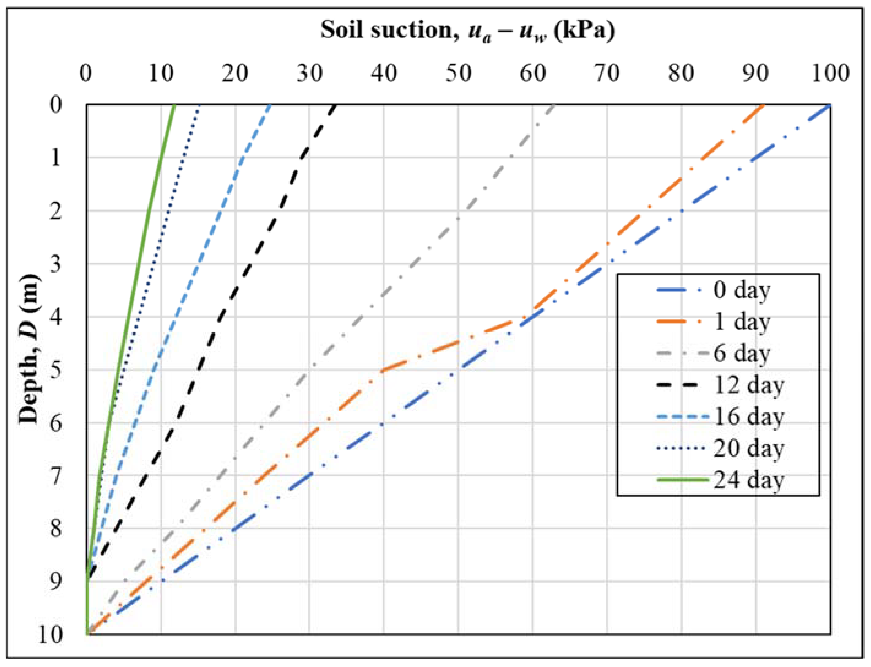
  • The boundary conditions in this model are the pressure head (GWT depth) and the rainfall that was applied to the surface of the entire model. The assigned rainfall patterns were a 12-day rain period followed by a 12-day drying period. The most precipitation in Astana, Kazakhstan, in 12 days is 20 mm per day [42]. Using fully coupled analysis, the volume and cycle of rainfall were incorporated into the groundwater phase of simulation.
The fundamental equation for the PLAXIS calculation is taken from Bentley [43], whose article discusses the PLAXIS 3D (Version 22) manual. The water infiltration in PLAXIS is based on Equation (8), which is a variant of the well-known Richards equation that describes the saturated–unsaturated groundwater flow. Meanwhile, in Equation (9), we are shown the original Richards equation based on Dogan and Motz [44].
n S k w s p w p w t + T k r ρ w × g × k s a t p w + ρ w × g = 0
x k x ( h ) × h x + y k y ( h ) × h y + y k z ( h ) × h z + 1 = C h + S × s s   h t
The specific storage ( s s ) is a material property which, neglecting the compressibility of the soil particles, can be expressed as Equation (10):
s s = n × ρ w × g k w
The term C h in the Richards equation can be expanded in Equation (11). By substituting Equations (10) and (11) into the original Richards equation (Equation (9)) and changing from a head-based equation to a pore-water-pressure-based equation, Equation (8) is obtained.
C h = θ h = h n S = n   s h  
where kx, ky, and kz—the permeability coefficients in the x, y and z directions, respectively; (∂θ/∂h)—specific moisture capacity (L−1); Ss—specific storage (L−1); ρw—density of water (kg/m3); g—gravitational acceleration (m/s2); ksat—permeability under saturated conditions (m/s); kw—unsaturated hydraulic conductivity (m/s); kr—relative water coefficient of permeability (kw/ks); S—degree of saturation of soil; and n—porosity of soil.

4. Results and Discussion

4.1. Analytical Calculations

4.1.1. β and Modified β Methods

Using the mechanical properties obtained from the laboratory experiments that are shown in Table 3 and Table 4, the shaft capacity of a 10 m pile was calculated for different GWT depths (2 m, 4 m, 6 m, 8 m, and 10 m). Figure 4 and Figure 5 show a comparison of the shaft capacity found using the conventional and modified β methods for coarse- and fine-grained soils. The computation was performed using pile lengths and groundwater table depths of 10 m, 8 m, 6 m, 4 m, and 2 m. Based on the fluctuation in the shear strength and the vertical effective stress with respect to the matric suction, which can be calculated from the SWCC [45], and effective shear strength parameters, the updated technique is utilized to calculate the shaft capacity [46].
The analytical calculations show that effective stress and matric suction significantly increase the pile foundation’s shaft capacity. In both cases, the modified method showed a greater shaft capacity value than the conventional method. Moreover, the shaft capacity reached its maximum in the middle of the embedded pile. That is to say that for coarse-grained soil (sand), the maximum capacity for a 10 m pile is at 5 m depth, showing 1280 kPa with the modified and 1180 kPa with the standard β method. Similarly, for fine-grained soil (kaolin), a pile of 10 m has a maximum capacity of 340 kPa and 240 kPa using the modified and conventional methods, respectively. All the other examples show the same trend, with a 100 kPa difference in shaft capacity with the modified β method, showing bigger values.
The function of the shaft capacity using the β and modified β methods has a D-shape, reaching its maximum capacity in the middle of the pile and decreasing to zero at the end of the total length. This can be explained using Equations (1) and (2). According to Vanapalli and Taylan [8], for the modified β method, the unsaturated conditions are dependent mainly on matric suction. This implies that when the pile reaches saturated conditions, the shaft capacity is set to zero, due to the absence of suction, and the capacity of the pile is fully dependent on the end-bearing.

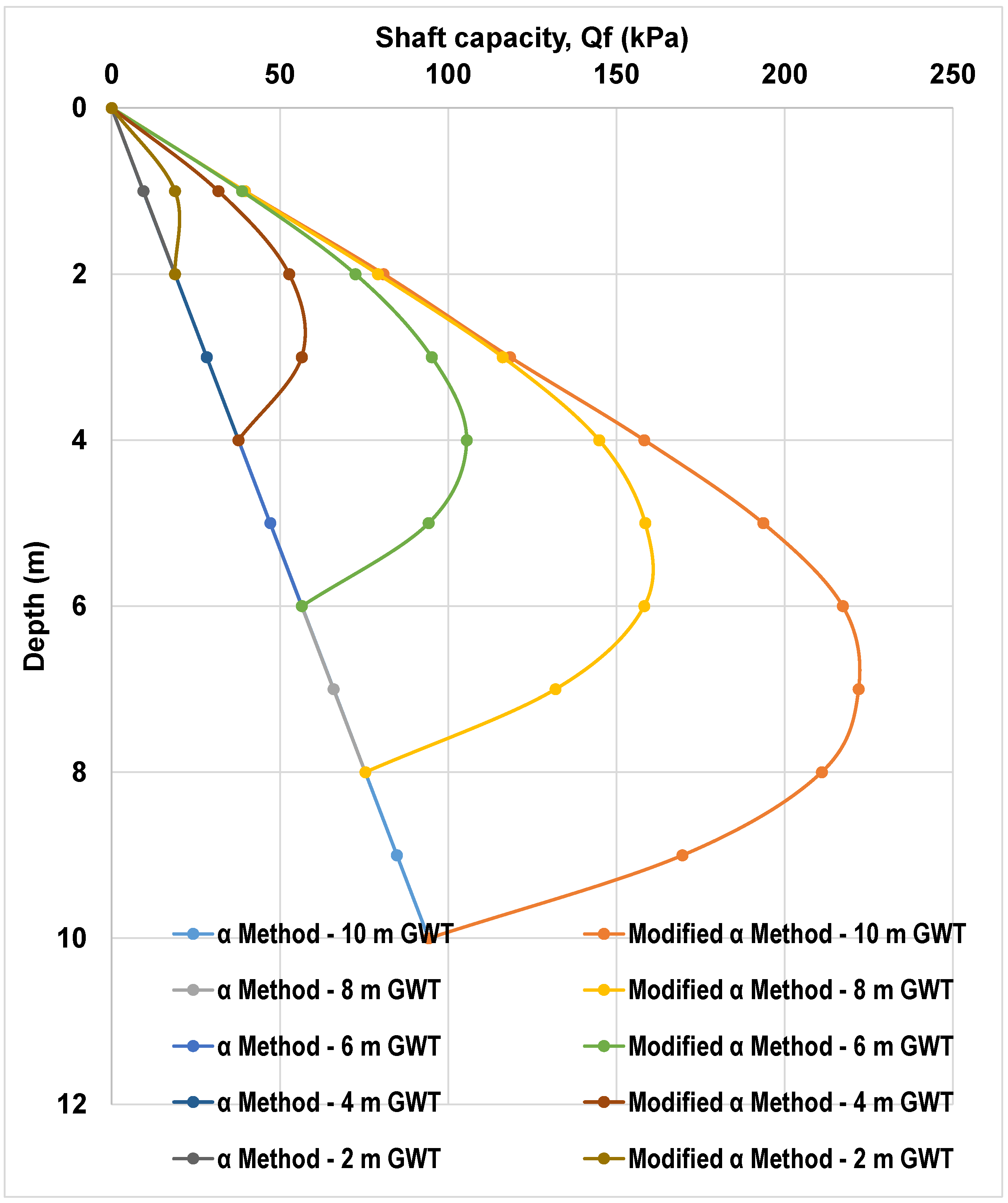
4.1.2. α and Modified α Methods
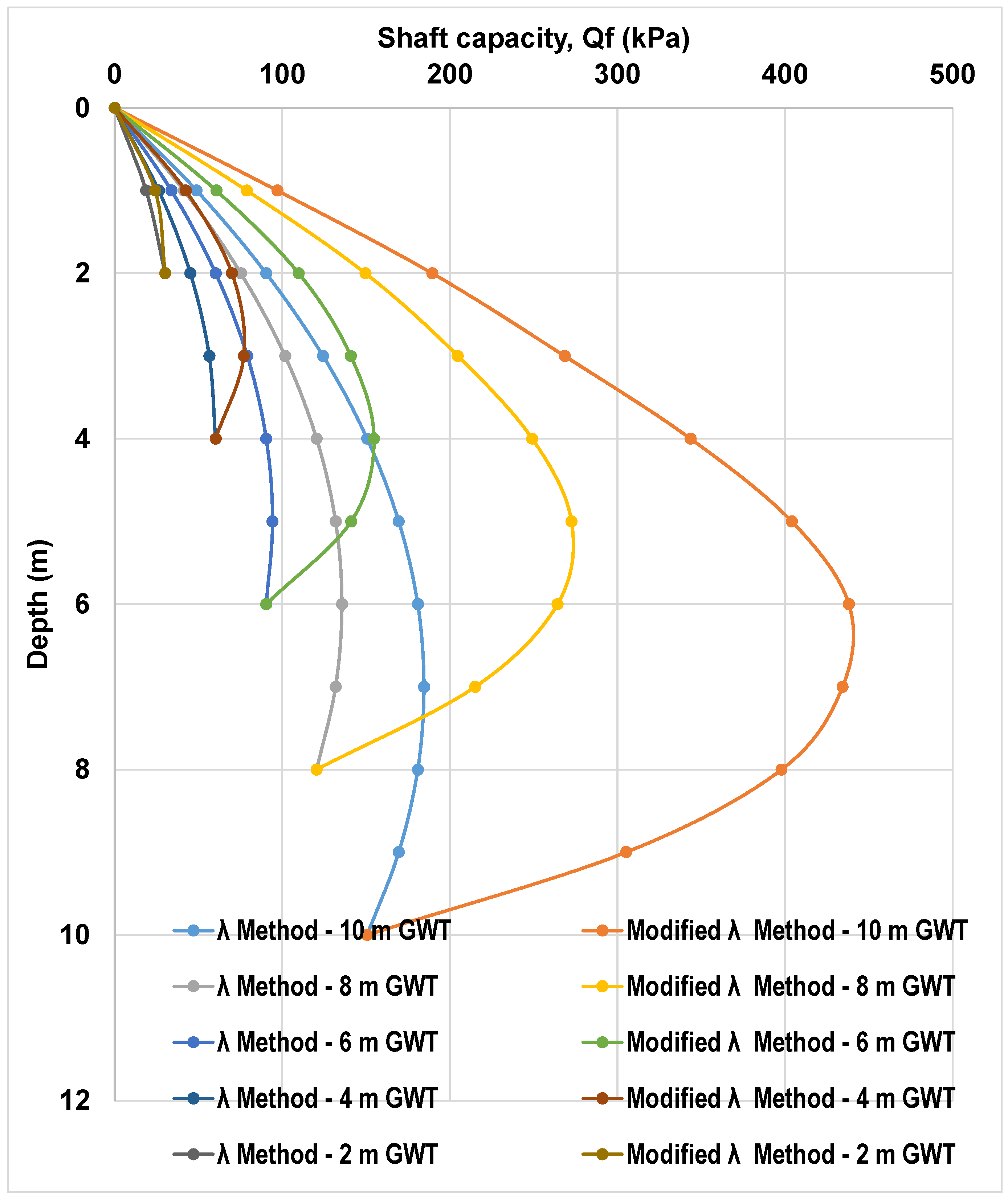
Figure 6 and Figure 7 represent the values of the calculated shaft capacity for piles and GWTs of 10, 8, 6, 4, and 2 m. Computations are applied to both fine-grained soil (kaolin) and coarse-grained soil (sand) using the α and modified α methods.
Overall, the modified α method results in a greater shaft capacity than the conventional one. The maximum shaft capacity of a 10 m pile in sand is at a depth of 7 m for the modified method (222 kPa) and at 10 m for the conventional method (94 kPa). For kaolin, the maximum capacity of a 10 m pile is at the same depth as in sand for both the modified α (150 kPa) and conventional α methods (63 kPa). For 8, 6, 4, and 2 m piles, for both sand and kaolin, the maximum shaft capacity using the modified α method is at 5.5, 4, 2.75 and 1.25 m, respectively. For the conventional method, its maximum, Q f , is at the bottom of the pile length.
Unlike the β methods, the conventional and modified α methods have different shapes for the function. For the conventional approach, the behaviour is linear, whereas for the modified approach, it is D-shaped. In addition, the shaft capacity in any of these cases does not reduce to 0 even when matric suction disappears. This is because the undrained shear still contributes to the shaft capacity of the pile and thus the value is never zero.

4.1.3. λ and Modified λ Methods

Figure 8 and Figure 9 show the values of the calculated shaft capacity for piles and GWTs of 10, 8, 6, 4, and 2 m. Computations are applied to both fine-grained soil (kaolin) and coarse-grained soil (sand) using the λ and modified λ methods.
The maximum shaft capacity for coarse- and fine-grained soil occurs when the GWT is at 10 m, and both are positioned at a pile depth of 6 m. The maximum value for the coarse-grained reaches close to 600 kPa, whereas the fine-grained reaches roughly 450 kPa. Overall, the behavior of each method reveals that the maximum capacity occurred when the GWT location was distant from the ground surface, as matric suction plays a vital role in supporting the extra capacity of the pile. When the GWT height accumulates near the ground surface, the capacity decreases, yet the modified approach still takes into account the residual state of the soil. Thus, the value remains higher than when using the original method.
In a similar fashion to the α method, the shaft capacity of the pile calculated using the λ method does not decrease to zero, even at the bottom of the pile. According to Equation (6), even if the suction is set to zero, the vertical effective stress and undrained shear strength will significantly contribute to the shaft capacity, not allowing it to reach the zero value. Both the conventional and modified λ methods have D-shape behavior, reaching the maximum value at approximately 67% of the embedded depth.

4.2. Numerical Analysis Using PLAXIS 3D (Version 22)

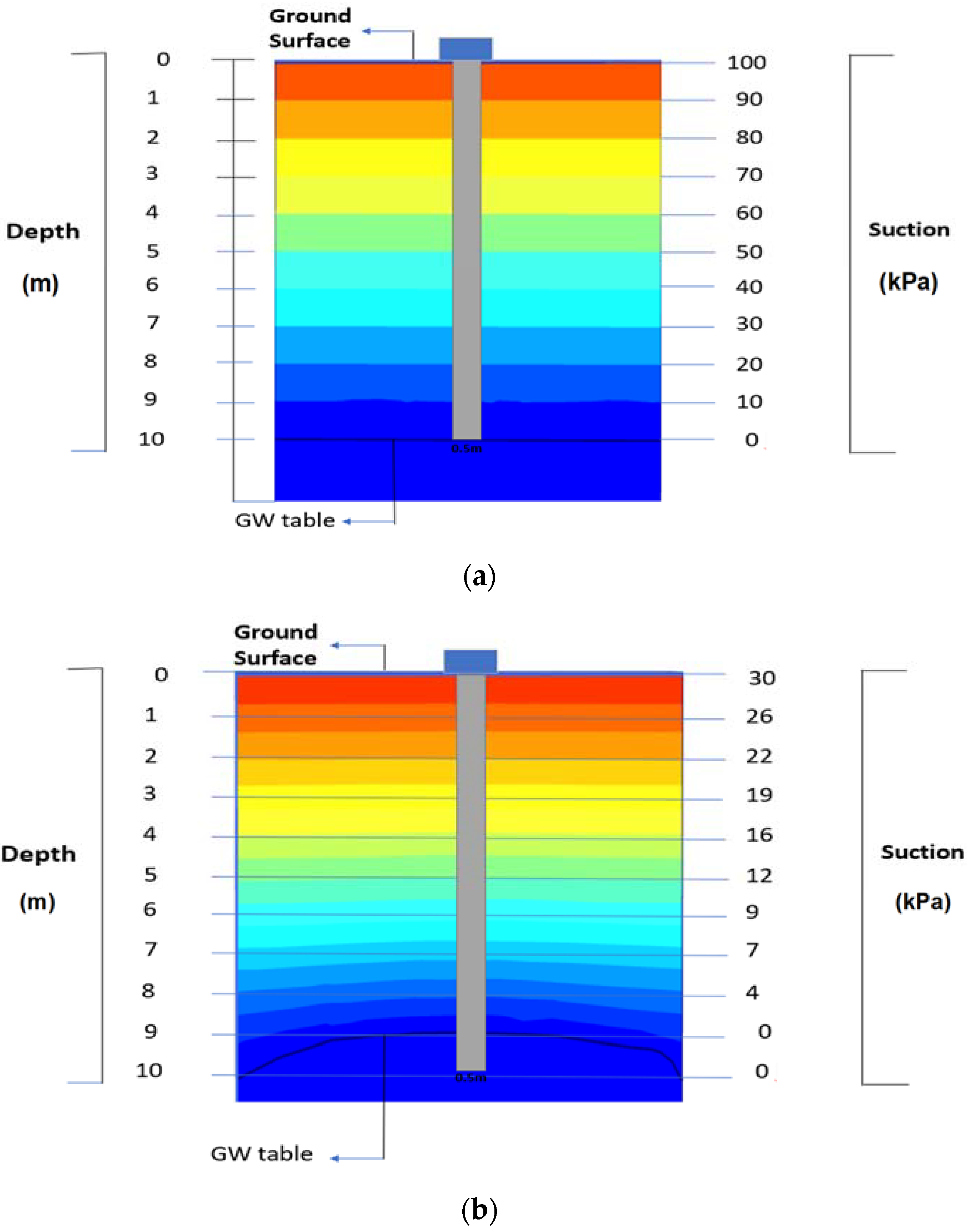
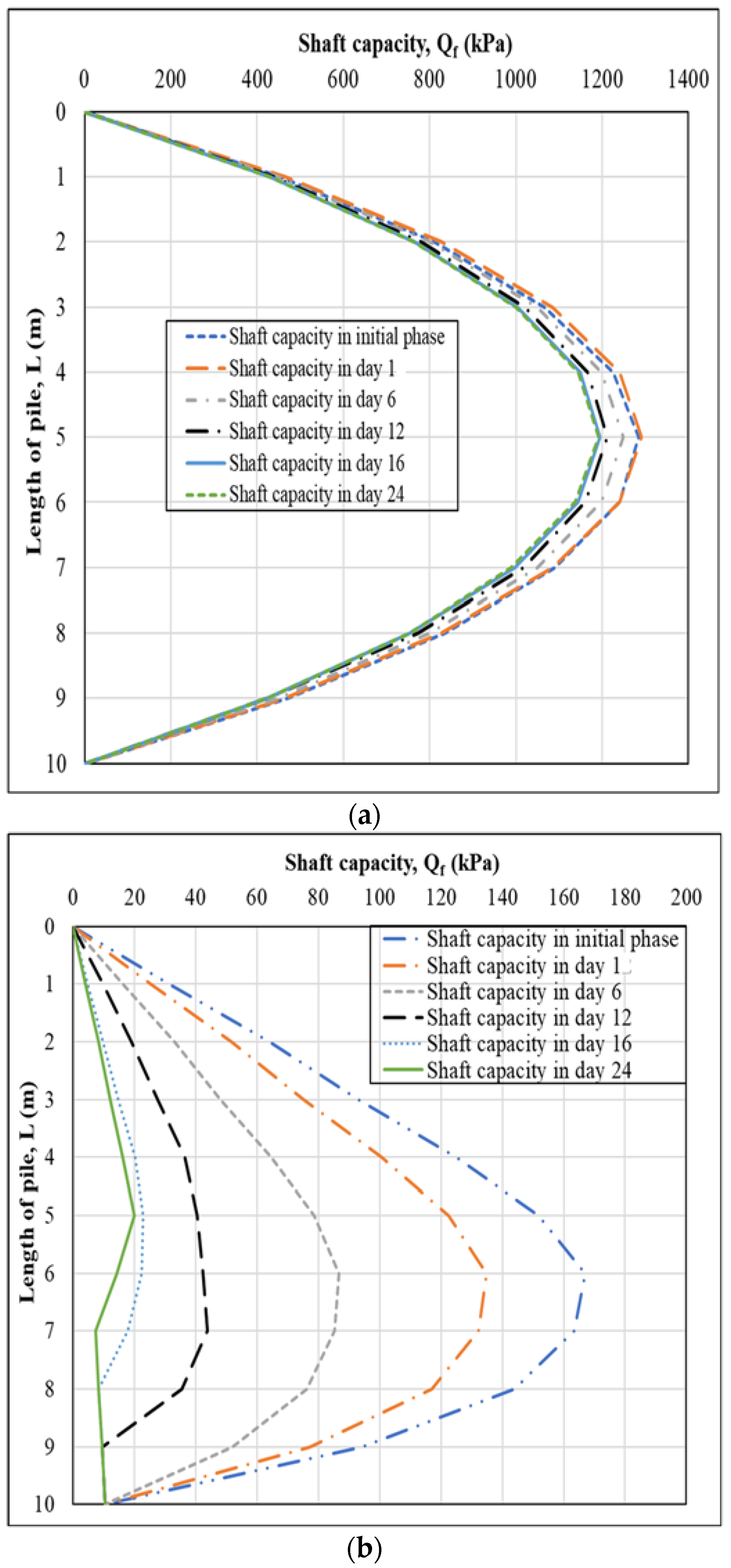
4.2.1. Results in Coarse-Grained Soil (Sand)

Rainfall-related variation in suction was examined using numerical analyses in PLAXIS 3D (Version 22). For the sake of this computation, a 10 m pile length was used. Equally, 12 days of rain were followed by 12 days of a dry period. According to Zhussupbekov et al. [42], the largest amount of rainfall in Astana was 20 mm for 12 days. For the purposes of the experiment, this was taken as the daily rainfall for a period of 12 days. The amount and the time interval of rainfall may be entered into the attribute library during the stage creation phase of modeling using PLAXIS. Editing the flow function in the settings will allow for the addition of a discharge function, where the time and quantity of precipitation can be included. Figure 10a,b represents the variation in suction at the initial phase and after the 12-day rainfall, respectively.
Figure 10 shows how the suction at the ground’s surface changes from 100 kPa to 30 kPa after 12 days of rainfall and decreases from 10 kPa to 0 kPa at a 9 m depth. The shaft capacity of the pile is reduced as a result of this drop in suction. In the coarse-grained soil (sand), the negative pore water pressure (matric suction) diminishes during periods of rainfall and during the ensuing dryness, as seen in Figure 11. In the first phase, the suction is contributing at its maximum rate of 100 kPa (day 0). It descends in a downward direction until it hits 10 kPa at the end of the simulation. After 12 days of rainfall, the soil suction drops from 100 kPa to 30 kPa, and then drops to 10 kPa at the end of the time, showing a 70 kPa reduction after 12 days of rainfall and a 90 kPa reduction over the course of the whole 15-day period.
The results from PLAXIS 3D (Version 22) were then incorporated into the modified β, α, and λ equations. In modified β, the soil’s shaft capacity was altered as a result of the rainfall, and the variations in the soil suction and the shaft capacity of the pile during the rainfall and drying period were calculated. The analytical computation results using the modified β method are shown in Figure 12a. According to the results of the modified β approach, the shaft capacity of the pile foundations decreases by 90 kPa as a result of the infiltration of rainwater, going from 1320 kPa during the initial phase to 1120 kPa after 12 days of rainfall. The shaft capacity falls from 1220 kPa to 1190 kPa over the 12 days of the dry period, a shift of 30 kPa. This pattern indicates that, due to the variations in suction, the shaft capacity decline will persist in dry periods after rainfall, but the change will be noticeably slower.
The results of the modified α method are depicted in Figure 12b. The modified α method results show that rainwater infiltration causes the shaft capacity of the pile foundation to drop by 115 kPa, from 168 kPa in the first phase to 44 kPa at the conclusion of the 12-day rainy period. The shaft capacity changes from 44 kPa to 20 kPa throughout the dry period of 12 days. As a result, the shaft capacity diminishes in dry periods at a far slower rate than it does in wet periods. Furthermore, the shaft capacity using the modified α method is highly affected by changes in suction, which can result in some uncertainties during computation and design. The results of an analytical computation utilizing the modified λ approach are shown in Figure 12c. Rainwater infiltration causes the shaft capacity of the pile foundations to decrease by 650 kPa, going from 1000 kPa in the beginning to almost 350 kPa at the end of the 12-day rainfall period. After 12 days of the dry period, the shaft capacity has decreased from 350 kPa to 130 kPa, indicating a 130 kPa variance in the pile’s shaft capacity. The modified λ method, similar to the modified α method, was severely affected by changes in the matric suction.

4.2.2. Results in Fine-Grained Soil (Kaolin)

Figure 13a displays a cross-section representation of the foundation and surrounding soil that was designed using PLAXIS 3D (Version 22). The cross-sectional view was obtained from a 3D model. The cross-section of the pile shows that the rainfall infiltration in the kaolin causes the matric suction to diminish. Before rain, it was 100 kPa, and by the end of the period under consideration, it was 12 kPa. Furthermore, it shows how the negative pore water pressure drops during the 12 days of dry time that follow the 12 days of rainfall due to water seeping into the groundwater table and into the depths. Figure 13b depicts the process by which suction changes to 33 kPa at the ground surface after 12 days of rainfall and then drops to 0 kPa at a depth of 10 m below the groundwater table. This suction reduction causes the shaft capacity of the pile to decrease.
The matric suction diminishes with rainfall and the subsequent dry interval. This is seen in Figure 14, where, in the first phase, the suction operates at its maximum rate of 100 kPa. It descends in a downward direction until it hits 12 kPa at the conclusion of the time. There is a 34 kPa maximum suction after 12 days of rain. The maximum suction after the dry period is 12 kPa. After 12 days of rainfall, the soil suction drops from 100 kPa to 34 kPa, and then it drops to 12 kPa by the conclusion, showing a 66 kPa reduction after 12 days of rainfall and an 88 kPa reduction after the whole 15-day period.
Similar to the coarse-grained soil, the results from PLAXIS 3D (Version 22) have also been analyzed with the modified β, α, and λ equations, which are illustrated in Figure 15a, Figure 15b and Figure 15c, respectively. The modified β method’s findings show that rainfall infiltration causes the shaft capacity of the pile foundations with fine-grained soil (kaolin) to decrease by 45 kPa, going from 320 kPa in the first phase to 275 kPa at the conclusion of the 12-day rainy period. In the dry period following a rainstorm, the shaft capacity of a pile within the kaolin soil reduces from 275 kPa to 155 kPa. According to the modified α method’s findings, the shaft capacity of the pile foundations decreases by 120 kPa as a result of the rainwater infiltration, going from 170 kPa during the first phase to 50 kPa after 12 days of rain. In the 12 days of the dry period, the shaft capacity of the pile foundation in the kaolin soil falls. It decreases from 50 kPa to 20 kPa, a difference of 30 kPa. In contrast, we see that the modified λ method’s findings show that rainwater infiltration causes the shaft capacity of pile foundations in fine-grained soil (kaolin) to decrease by 820 kPa, going from 1000 kPa in the first phase to almost 180 kPa at the conclusion of the rainy period. Due to reduced suction, the pile’s shaft capacity will continue to decline over the dry period. It changes from 180 kPa to 70 kPa, which is a change of 110 kPa.
According to the outcome of the numerical calculations, rainfall infiltration in both fine- and coarse-grained soil causes a decrease in suction. For coarse-grained soil (sand), the initial suction is 100 kPa (before rainfall infiltration), declining to 80 kPa after one day of continuous rain, 30 kPa after 12 days, and 10 kPa at the conclusion of the time. Similarly, the analyses indicate that the suction within the fine-grained soil decreases from 100 kPa on the day before the rainfall to 90 kPa on the first day of rainfall and to 34 kPa after 12 days of rainfall, continuing to decline to 12 kPa at the end of the 15-day period. This shows that even after 12 days of rain, water continues to flow into the water table and attempts to equalize with the surrounding environment, lowering the negative pore water pressure. Additionally, due to rainfall, the GWT depth lowers from its original assumption of 10 m to 9 m at the conclusion of the time. The outcome also shows that as a result of the water infiltration into the groundwater table and into the depths, the negative pore water pressure decreases during the 12 days of the drying period that follows the 12 days of rainfall.
The analytical calculations using modified β, α, and λ were used to calculate the shaft capacity of piles at various GWT depths. The results were then incorporated into PLAXIS 3D (Version 22) to determine the shift in the shaft capacity of piles due to transient seepage. This method shows that the analytical method serves as an initial forecast of the pile shaft capacity. The PLAXIS results were more accurate than the analytical results since they were based on finite element analysis with a fine mesh division. As can be observed from the results, parametric studies produce different results from analytical studies due to the complexity of the model with the boundary conditions and the possibility of human error during the computation process.
Overall, both datasets provide us with information about the rate of decline in the shaft capacity of piles due to the presence of soil suction. For instance, the shaft capacity of a 10 m pile in coarse-grained soil reduces from 1280 to 1120 kPa (modified β method), from 168 to 44 kPa (modified α method), and from 1000 to 350 kPa (modified λ method) during the 12 days of rainfall. Similarly, the shaft capacity of a 10 m pile in fine-grained soil reduces from 320 to 275 kPa (modified β method), from 170 to 50 kPa (modified α method), and from 1000 to 180 kPa (modified λ method) during the 12 days of rainfall. According to the results, the pile foundation within the coarse-grained soil has a higher shaft capacity as compared to the fine-grained soil. The shaft capacity of a pile calculated using the modified β method is higher compared to the modified α and modified λ methods due to the influence of effective stress. The modified β method was found to be the most resistant to changes in suction due to rainfall infiltration as compared to the modified α and λ approaches. It was concluded that the modified β method can be used for longer piles, but for short piles, the α and λ methods are more sustainable.

5. Conclusions

According to the obtained results in this research, unsaturated soil mechanics create a larger shaft capacity for pile foundations. Rainfall also weakens the suction in the soil, which lowers the pile foundation’s shaft capacity in both coarse- and fine-grained soil. With regards to this paper’s research work, the following conclusions were obtained:
  • Rainfall has an effect on the rate of suction in the soil, which reduces even after the rain has stopped. This is due to water equalization in the surrounding environment, which is taken into consideration. Because there is no additional water seeping into the ground, the suction reduction rate tends to slow throughout the drying period.
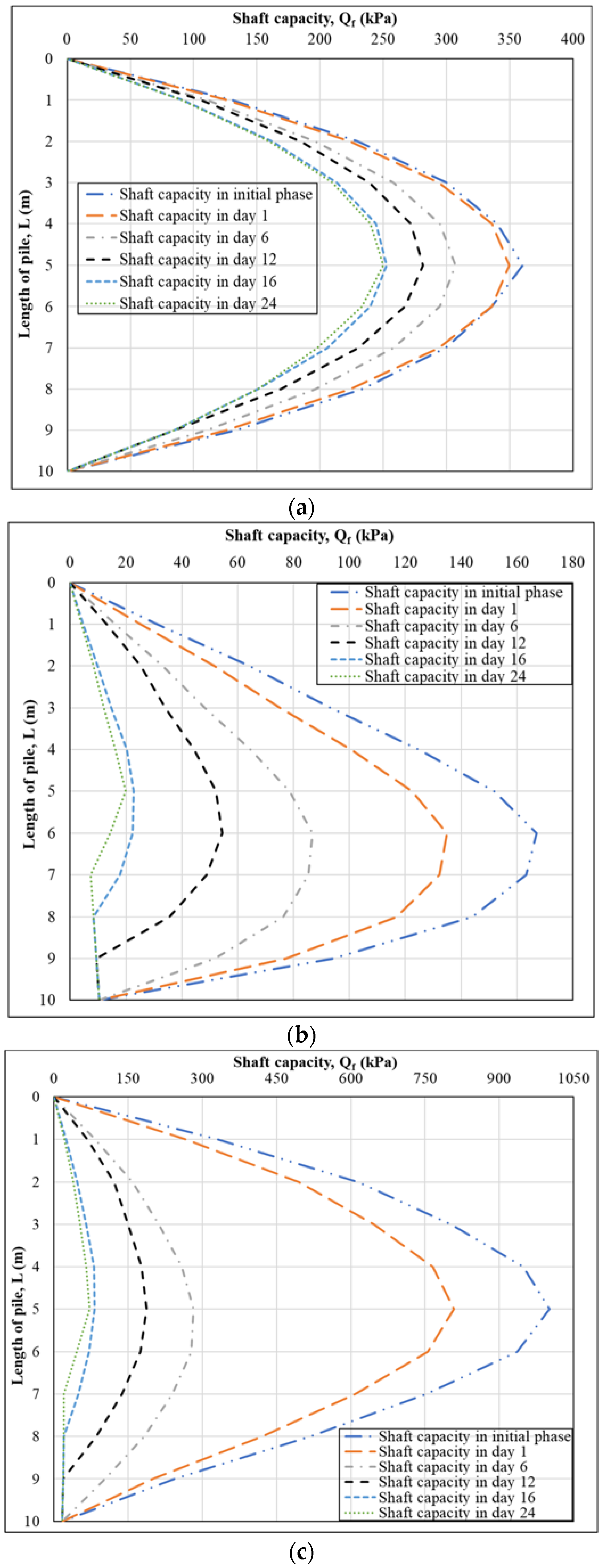
  • Analytical calculations incorporating negative pore water pressure indicated that the modified methods (β, α, and λ) consistently produced higher shaft capacities for pile foundations. The differences between the conventional and modified methods were significant, emphasizing the importance of considering negative pore water pressure. Unsurprisingly, the study recommended the use of unsaturated soil in the foundation design for a higher shaft capacity and pile optimization.
  • The analytical calculation, incorporating PLAXIS 3D (Version 22) for the numerical study, showed a decline in the shaft capacity of piles with increasing soil suction. The study provided specific examples, indicating that coarse-grained soil generally has a higher shaft capacity compared to fine-grained soil.
  • The modified β method was found to have a higher shaft capacity, attributed to the influence of effective stress. It was suggested that the modified β method is suitable for longer piles, while the modified α and λ methods are more sustainable for short piles.
  • Sustainable pile design involves using resources efficiently and minimizing environmental impact. Understanding unsaturated soil mechanics can aid in optimizing the design to utilize local soil conditions effectively, reducing the need for excessive material use or environmental disruption.
In summary, the research underscores the importance of considering unsaturated soil mechanics, a negative pore water pressure, and the influence of rainfall in designing pile foundations. The findings provide valuable insights for optimizing the pile design based on the soil type and environmental conditions.

Author Contributions

Conceptualization: G.D.A., A.S. (Alfrendo Satyanaga) and A.S. (Aizhan Sagu); investigation: G.D.A., G.P. and B.S.; methodology: G.D.A., A.S. (Alfrendo Satyanaga) and B.A.; writing—original draft: G.D.A., A.S. (Alfrendo Satyanaga) and G.P.; supervision: A.S. (Alfrendo Satyanaga), Q.Z. and J.K.; funding acquisition: A.S. (Alfrendo Satyanaga); resources: B.S., G.P. and J.K.; data curation: B.S., G.P. and B.A.; validation: G.D.A. and Q.Z.; software: Q.Z. and A.S. (Aizhan Sagu); formal analysis: G.D.A., A.S. (Aizhan Sagu), B.S. and G.P.; writing—review and editing: B.A., Q.Z. and J.K.; project administration: A.S. (Alfrendo Satyanaga) and J.K. All authors have read and agreed to the published version of the manuscript.

Funding

This research was supported by the Nazarbayev University Research Fund under the Faculty Development Competitive Research Grants Program (FDCRGP), grant no. 20122022FD4133. The authors are grateful for this support. Any opinions, findings, and conclusions or recommendations expressed in this material are those of the author(s) and do not necessarily reflect the views of Nazarbayev University.

Institutional Review Board Statement

Not applicable.

Informed Consent Statement

Not applicable.

Data Availability Statement

Data are available upon request.

Acknowledgments

The authors would like to express their sincere gratitude for the tremendous assistance from Allah Bahman Ibrahimi during the collection of data for the study.

Conflicts of Interest

The authors declare no conflict of interest.

References

  1. Fredlund, D.G.; Sheng, D.; Zhao, J. Estimation of soil suction from the soil-water characteristic curve. Can. Geotech. J. 2011, 48, 186–198. [Google Scholar] [CrossRef]
  2. Habasimbi, P.; Nishimura, T. Soil water characteristic curve of an unsaturated soil under low matric suction ranges and different stress conditions. Int. J. Geosci. 2019, 10, 39–56. [Google Scholar] [CrossRef]
  3. Kim, Y.; Satyanaga, A.; Rahardjo, H.; Park, H.; Sham, A.W.L. Estimation of effective cohesion using artificial neural networks based on index soil properties: A Singapore case. Eng. Geol. 2012, 289, 106163. [Google Scholar] [CrossRef]
  4. Vanapalli, S.K.; Garga, V.K.; Brisson, P. A modified permeameter for determination of unsaturated coefficient of permeability. Geotech. Geol. Eng. 2007, 25, 191–202. [Google Scholar] [CrossRef]
  5. Vanapalli, S.; Eigenbrod, K.; Taylan, Z.; Catana, C.; Oh, W.; Garven, E. A technique for estimating the shaft resistance of test piles in unsaturated soils. In Proceedings of the 5th International Conference Unsaturated Soils UNSAT, Barcelona, Spain, 6–8 September 2010. [Google Scholar]
  6. Vanapalli, S.K.; Lu, L.; Sedano, J.A.I.; Oh, W.T. Swelling Characteristics of Sand-Bentonite Mixtures. In Unsaturated Soils: Research and Applications; Springer: Berlin/Heidelberg, Germany, 2012; pp. 77–84. [Google Scholar]
  7. Ng, C.W.W.; Pang, Y.W. Influence of stress state on soil-water characteristics and slope stability. J. Geotech. Geoenviron. Eng. 2000, 126, 157–166. [Google Scholar] [CrossRef]
  8. Vanapalli, S.; Taylan, Z.N. Model piles behaviour in a compacted fine-grained unsaturated soil. In Proceedings of the 15th European Conference on Soil Mechanics and Geotechnical Engineering, Athens, Greece, 15 September 2011; IOS Press: Amsterdam, The Netherlands, 2011. [Google Scholar]
  9. Sun, W.J.; Cui, Y.J. Investigating the microstructure changes for silty soil during drying. Geotechnique 2018, 68, 370–373. [Google Scholar] [CrossRef]
  10. Morris, P.H.; Graham, J.; Williams, D.J. Cracking in drying soils. Can. Geotech. J. 1992, 29, 263–277. [Google Scholar] [CrossRef]
  11. al-Omari, R.R.; Fattah, M.Y.; Kallawi, A.M. Bearing capacity of piles in unsaturated soil from theoretical and experimental approaches. In Proceedings of the 4th International Conference on Buildings, Construction and Environmental Engineering, Istanbul, Turkey, 7–9 October 2019; Volume 737, p. 012101. [Google Scholar]
  12. Thota, S.K.; Vahedifard, F. A model for ultimate bearing capacity of piles in unsaturated soils under elevated temperatures. In Proceedings of the 2nd International Conference on Energy Geotechnics (ICEGT 2020), San Diego, CA, USA, 20–23 September 2020; Volume 205, p. 05003. [Google Scholar]
  13. Santos, D.B.; Lemos, M.A.D.C.; Cavalcante, A.L.B. Transient unsaturated shaft resistance of a single pile during water flow. In Proceedings of the PanAm-UNSAT 2021: 3rd Pan-American Conference on Unsaturated Soils, Rio de Janeiro, Brazil, 26–28 July 2021; Volume 337, p. 03007. [Google Scholar]
  14. Liu, Y.; Vanapalli, S.K. Mechanical behavior of a floating model pile in unsaturated expansive soil associated with water infiltration: Laboratory investigations and numerical simulations. Soils Found. 2021, 61, 929–943. [Google Scholar] [CrossRef]
  15. Buranbayeva, A.; Zhussupbekov, A.Z.; Omarov, A. Numerical analysis and geomonitoring of behaviour of foundation of Abu-Dhabi Plaza in Nur-Sultan. In Proceedings of the Deep Foundations and Geotechnical Problems of Territories (DFGC 2021), Perm, Russian, 26–28 May 2021; IOP Publishing: Amsterdam, The Netherlands, 2021. [Google Scholar]
  16. Nowamooz, H.; Masrouri, F. Suction variations and soil fabric of swelling compacted soils. J. Rock Mech. Geotech. Eng. 2010, 2, 129–134. [Google Scholar] [CrossRef]
  17. Rahardjo, H.; Satyanaga, A.; Leong, E.C. Effects of rainfall characteristics on the stability of tropical residual soil slope. In Proceedings of the 3rd European Conference on Unsaturated Soils E-UNSAT 2016, Paris, France, 12–14 September 2016; EDP Sciences: Paris, France, 2016. [Google Scholar]
  18. Vorwerk, S.; Cameron, D.; Keppel, G. Chapter 22—Clay Soil in Suburban Environments: Movement and Stabilization through Vegetation. In Ground Improvement Case Histories; Indraratna, B., Chu, J., Rujikiatkamjorn, C., Eds.; Butterworth-Heinemann: Oxford, UK, 2015; pp. 655–682. [Google Scholar]
  19. Vanapalli, S.K.; Fredlund, D.G.; Pufahl, D.E. The influence of soil structure and stress history on the soil–water characteristics of a compacted till. Geotechnique. 1999, 49, 143–159. [Google Scholar] [CrossRef]
  20. Tavakoli Dastjerdi, M.H.; Habibagahi, G.; Nikooee, E. Effect of confining stress on soil water retention curve and its impact on the shear strength of unsaturated soils. Vadose Zone J. 2014, 13, vzj2013.05.0094. [Google Scholar] [CrossRef]
  21. van Genuchten, M.T. A closed-form equation for predicting the hydraulic conductivity of unsaturated soils. Soil Sci. Soc. Am. J. 1980, 44, 892–898. [Google Scholar] [CrossRef]
  22. Yan, W.; Birle, E.; Cudmani, R. A new framework to determine general multimodal soil water characteristic curves. Acta Geotech. 2021, 16, 3187–3208. [Google Scholar] [CrossRef]
  23. Zhang, L.; Chen, Q. Predicting bimodal soil–water characteristic curves. J. Geotech. Geoenviron. Eng. 2005, 131, 666–670. [Google Scholar] [CrossRef]
  24. Tinjum, J.M.; Benson, C.H.; Blotz, L.R. Soil-water characteristic curves for compacted clays. J. Geotech. Geoenviron. Eng. 1997, 123, 1060–1069. [Google Scholar] [CrossRef]
  25. Kocaman, K.; Ozocak, A.; Edil, T.B.; Bol, E.; Sert, S.; Onturk, K.; Ozsagir, M. Evaluation of Soil-Water Characteristic Curve and Pore-Size Distribution of Fine-Grained Soils. Water 2022, 14, 3445. [Google Scholar] [CrossRef]
  26. Tarantino, A. A water retention model for deformable soils. Geotechnique 2009, 59, 751–762. [Google Scholar] [CrossRef]
  27. Douthitt, B.; Houston, W.; Houston, S.; Walsh, K. Effect of wetting on pile friction. In Proceedings of the 2nd International Conference on Unsaturated Soils (UNSAT’98), Beijing, China, 27–30 August 1998. [Google Scholar]
  28. Costa, Y.D.; Cintra, J.C.; Zornberg, J.G. Influence of matric suction on the results of plate load tests performed on a lateritic soil deposit. Geotech. Test. J. 2003, 26, 219–227. [Google Scholar]
  29. Georgiadis, K.; Potts, D.; Zdravkovic, L. The influence of partial soil saturation on pile behaviour. Géotechnique 2003, 53, 11–25. [Google Scholar] [CrossRef]
  30. Lu, N. Unsaturated Soil Mechanics: Fundamental Challenges, Breakthroughs, and Opportunities. J. Geotech. Geoenviron. Eng. 2020, 146, 02520001. [Google Scholar] [CrossRef]
  31. Skempton, A. Cast in-situ bored piles in London clay. Geotechnique 1959, 9, 153–173. [Google Scholar] [CrossRef]
  32. Burland, J. Shaft Friction of Piles in Clay—A Simple Fundamental Approach; Ground Engineering: London, UK, 1973; Volume 6. [Google Scholar]
  33. Focht, J.A.; Vijayvergiya, V. A new way to predict capacity of piles in clay. In Proceedings of the Offshore Technology Conference, Houston, TX, USA, 1–3 May 1972; OTC: Richardson, TX, USA, 1972. [Google Scholar]
  34. Becker, D.E. Eighteenth Canadian Geotechnical Colloquium: Limit States Design For Foundations. Part I. An overview of the foundation design process. Can. Geotech. J. 1996, 33, 956–983. [Google Scholar] [CrossRef]
  35. Pachikin, K.; Erokhina, O.; Funakawa, S. Soils of Kazakhstan, their distribution and mapping. In Novel Measurement and Assessment Tools for Monitoring and Management of Land and Water Resources in Agricultural Landscapes of Central Asia; Springer: Cham, Switzerland, 2014; pp. 519–533. [Google Scholar]
  36. Fredlund, M.D.; Wilson, G.W.; Fredlund, D.G. Representation and estimation of the shrinkage curve. In Proceedings of the 3rd International Conference on Unsaturated Soils UNSAT’2002, Recife, Brazil, 10–13 March 2002; pp. 145–149. [Google Scholar]
  37. Hakro, M.R.; Kumar, A.; Almani, Z.; Ali, M.; Aslam, F.; Fediuk, R.; Klyuev, S.; Klyuev, A.; Sabitov, L. Numerical Analysis of Piled-Raft Foundations on Multi-Layer Soil Considering Settlement and Swelling. Buildings 2022, 12, 356. [Google Scholar] [CrossRef]
  38. Fredlund, D.G.; Xing, A. Equations for the soil-water characteristic curve. Can. Geotech. J. 1994, 31, 521–532. [Google Scholar] [CrossRef]
  39. Leong, E.C.; Rahardjo, H. Review of Soil-Water Characteristic Curve Equations. J. Geotech. Geoenviron. Eng. 1997, 123, 1106–1117. [Google Scholar] [CrossRef]
  40. Leong, E.C.; Rahardjo, H. Permeability functions for unsaturated soils. J. Geotech. Geoenviron. Eng. 1997, 123, 1118–1126. [Google Scholar] [CrossRef]
  41. Labuz, J.F.; Zang, A. Mohr–Coulomb Failure Criterion. Rock Mech. Rock Eng. 2012, 45, 975–979. [Google Scholar] [CrossRef]
  42. Zhussupbekov, A.; Shin, E.C.; Shakhmov, Z.; Tleulenova, G. Experimental study of model pile foundations in seasonally freezing soil ground. Geomate J. 2018, 15, 85–90. [Google Scholar] [CrossRef]
  43. Bentley. PLAXIS 3D Reference Manual. 2022. Available online: https://communities.bentley.com/cfs-file/__key/communityserver-wikis-components-files/00-00-00-05-58/PLAXIS_5F00_3D_5F00_CEV22.01_5F00_2_2D00_Reference.pdf (accessed on 30 November 2023).
  44. Dogan, A.; Motz, L.H. Saturated-Unsaturated 3D Groundwater Model. I: Development. J. Hydrol. Eng. 2005, 10, 492–504. [Google Scholar] [CrossRef]
  45. Satyanaga, A.; Rahardjo, H. Role of unsaturated soil properties in the development of slope susceptibility map. Proc. Inst. Civ. Eng. 2022, 175, 276–288. [Google Scholar] [CrossRef]
  46. Vanapalli, S.K.; Taylan, Z.N. Design of Single Piles Using the Mechanics of Unsaturated Soils. Geomate J. 2012, 2, 197–204. [Google Scholar]
Figure 1. Unsaturated permeability of (a) sand and (b) kaolin using Leong & Rahardjo [40].
Sustainability 16 00313 g001
Figure 2. SWCC for the coarse-grained soil (sand).
Sustainability 16 00313 g002
Figure 3. SWCC for the fine-grained soil (kaolin).
Sustainability 16 00313 g003
Figure 4. Shaft capacity of pile with groundwater table (GWT) at 10 m, 8 m, 6 m, 4 m, 2 m in coarse-grained soil using β and modified β methods.
Sustainability 16 00313 g004
Figure 5. Shaft capacity of pile with groundwater table (GWT) at 10 m, 8 m, 6 m, 4 m, 2 m in fine-grained soil using β and modified β methods.
Sustainability 16 00313 g005
Figure 6. Shaft capacity of pile with groundwater tables (GWTs) at 10 m, 8 m, 6 m, 4 m, 2 m in coarse-grained soil (sand) using α and modified α methods.
Sustainability 16 00313 g006
Figure 7. Shaft capacity of pile with GWTs at 10 m, 8 m, 6 m, 4 m, 2 m in fine-grained soil (kaolin) using α and modified α methods.
Sustainability 16 00313 g007
Figure 8. Shaft capacity of pile with GWTs at 10 m, 8 m, 6 m, 4 m, 2 m in coarse-grained soil (sand) using λ and modified λ methods.
Sustainability 16 00313 g008
Figure 9. Shaft capacity of pile with GWTs at 10 m, 8 m, 6 m, 4 m, 2 m in fine-grained soil (kaolin) using λ and modified λ methods.
Sustainability 16 00313 g009
Figure 10. PLAXIS 3D (Version 22) model in sand—(a) initial phase; (b) suction variation after rainfall.
Sustainability 16 00313 g010
Figure 11. Suction variation in sand with respect to depth.
Sustainability 16 00313 g011
Figure 12. Analytical calculation results of shaft capacity for sand after rainfall—(a) modified β; (b) modified α; and (c) modified λ.
Sustainability 16 00313 g012aSustainability 16 00313 g012b
Figure 13. PLAXIS 3D (Version 22) model in kaolin—(a) initial phase; (b) suction variation after rainfall.
Sustainability 16 00313 g013
Figure 14. Suction variation of kaolin with respect to depth.
Sustainability 16 00313 g014
Figure 15. Analytical calculation result of kaolin shaft capacity after rainfall—(a) modified β; (b) modified α; and (c) modified λ.
Sustainability 16 00313 g015
Table 1. Laboratory tests based on ASTM standard.
Index Property TestsASTM Code
Compaction standard proctorD698-12
Grain size distribution
Sieve analysisD6913-04
Hydrometer analysisD7928-21
Atterberg limitsD4318-10
Soil–water characteristic curve using HYPROPD6836-92
Permeability test using constant headD2434-19
Triaxial testing using consolidated undrained soilD4767-11
Table 2. Laboratory tests based on ASTM standard.
SoilCohesion, c′ (kPa)Friction Angle, ϕ′ (°)Unit Weight, γ (kN/m3)Unsaturated Friction Angle, ϕb (°)
Kaolin182314 11.5
Sand04515 22.5
Table 3. Soil data used for foundation modeled in sand soil using PLAXIS 3D (Version 22).
Soil typeSand
Soil modelMohr–Coulomb
Drainage typeDrained
Unsaturated unit weight, γunsat16 kN/m3
Saturated unit weight, γsat20 kN/m3
Void ratio, e0.71
Modulus of elasticity, E430 kPa
Cohesion, c0 kPa
Friction angle, ϕ45°
Table 4. Soil data used for foundation modeled in kaolin soil using PLAXIS 3D.
Soil typeKaolin
Soil modelMohr–Coulomb
Drainage typeDrained
Unsaturated unit weight, γunsat18.3 kN/m3
Saturated unit weight, γsat20.83 kN/m3
Void ratio, e0.2
Modulus of elasticity, E15.76 kPa
Cohesion, c18 kPa
Friction angle, ϕ14°
Disclaimer/Publisher’s Note: The statements, opinions and data contained in all publications are solely those of the individual author(s) and contributor(s) and not of MDPI and/or the editor(s). MDPI and/or the editor(s) disclaim responsibility for any injury to people or property resulting from any ideas, methods, instructions or products referred to in the content.

