Article

Continuous Power Management of Decentralized DC Microgrid Based on Transitional Operation Modes under System Uncertainty and Sensor Failure

1
Department of Electrical and Information Engineering, Seoul National University of Science and Technology, 232 Gongneung-ro, Nowon-gu, Seoul 01811, Republic of Korea
2
Purpose Built Mobility Group, Korea Institute of Industrial Technology, 6 Choemdan-gwagiro 208-gil, Buk-gu, Gwangju 61012, Republic of Korea
*
Author to whom correspondence should be addressed.
Sustainability 2024, 16(12), 4925; https://doi.org/10.3390/su16124925
Submission received: 27 March 2024 / Revised: 5 June 2024 / Accepted: 6 June 2024 / Published: 8 June 2024
(This article belongs to the Special Issue Renewable Energy Technologies and Microgrids)

Abstract

:
Continuous power management for a decentralized DC microgrid (DCMG) is proposed in this study to achieve power balance and voltage regulation even under system uncertainty and voltage sensor failure. The DCMG system achieves continuous power management through only the primary controller to reduce the computational burden of each power agent. To enhance the reliability and resilience of the DCMG system under DC bus voltage (DCV) sensor failure, a DCV sensor fault detection algorithm is suggested. In this algorithm, DCV sensor failure is detected by comparing the measured DCV with the estimated DCV. If power agents identify the failure of the DCV sensor, it changes the operation properly according to the proposed control mode decision algorithm to guarantee the stability of the DCMG system. When uncertain conditions like sudden grid disconnection, DCV sensor failure, electricity price change, power variation in distributed generations, and critical battery status occur, the DCMG system is changed to transitional operation modes. These transitional operation modes are employed to transmit the power agent information to other agents without digital communication links (DCLs) and to accomplish power sharing even under such uncertain conditions. In the transitional operation modes of the DCMG system, the DCV levels are temporarily shifted to an appropriate level, enabling each power agent to detect the uncertainty conditions, and subsequently to determine its operation modes based on the DCV levels. The reliability and effectiveness of the proposed control strategy are confirmed via various simulation and experimental tests under different operating conditions.

1. Introduction

Interest in sustainable and renewable energy is increasing due to environmental problems such as greenhouse gas emissions and fossil fuel depletion [1,2]. With the increasing demand for cleaner energy, the microgrid system has emerged as a promising solution to generate and distribute electrical energy. By using the microgrid, the distributed generations based on renewable energy sources, utility grid, energy storage systems (ESSs), and loads are interconnected efficiently and reliably to overcome the limitation caused by the intermittent nature of renewable energy, which provides a sustainable alternative to the conventional power grid [3,4,5]. By harnessing diverse renewable energy sources, microgrids contribute to reducing the carbon footprint and enhance energy resilience. Microgrid systems that are efficient and robust for the use of distributed energy sources are usually composed of ESSs, loads, and distributed generations such as a wind turbine and photovoltaic (PV) device [6].
Depending on the type of power supplied, the microgrid configuration is divided into the DC microgrid, AC microgrid (ACMG), and hybrid AC/DC microgrid [7]. Among these structures, DCMG stands out for its simplicity and efficiency. Unlike hybrid AC/DC and AC microgrids, the DCMG minimizes unnecessary power conversion stages and reduces technical challenges such as synchronization, harmonics, and reactive power [8,9,10,11]. Furthermore, DC energy sources such as fuel cells, PV, supercapacitors, or batteries are easily interconnected in the DCMG system [12].
According to the configuration of the digital communication link (DCL), the control strategy for the DCMG system is categorized into three main types: centralized control, decentralized control, and distributed control [13,14,15]. The centralized control strategy uses a central controller that communicates with all power agents via DCLs to determine the operation modes of each power agent [16,17]. The distributed control strategy also uses DCL to communicate with adjacent power agents. However, in the distributed control method, power agents determine the proper operation modes with a limited DCL to adjacent power agents without relying on a central controller [18,19]. It is important to note that the transmission time delay caused by the DCL that is unavoidable in both the distributed and centralized controls might negatively impact the efficiency and stability of the DCMG system [3]. A decentralized control strategy can be employed as an alternative way to solve this weakness. In the decentralized control method, the operation modes of the DCMG system are properly determined based on only local measurements such as the DCV, without using any DCL between power agents [20]. In addition, power agents normally operate independently in the decentralized DCMG system without the use of any DCL, which significantly increases the simplicity, scalability, and flexibility of the DCMG system [21,22].
Generally, the DCV is utilized as global information for powers agent in the decentralized DCMG system [23,24,25,26]. If the DCV decreases from the nominal DCV value, it indicates that the power supply to the DC bus is less than the power demand. In contrast, if the DCV increases from the nominal DCV value, it means that there is power surplus in the DCMG system. Traditionally, the droop control strategy is employed in decentralized DCMG systems to control the DCV to the nominal value [27,28,29,30,31]. In the study in [29], DCMG power balance is achieved by using a voltage–current (V-I) droop controller according to the DCV level. To overcome the weakness of the DCV fluctuation in this scheme, the researchers in [31,32] proposed the use of an integral term in the secondary controller for ensuring DCV restoration to the nominal value. The secondary control strategy is used in these methods to regulate the DCV to its nominal value, while the primary control strategy is employed to maintain the power balance in the decentralized DCMG system. Although the voltage fluctuation problem caused by the droop controller is mitigated by combining the primary and secondary controls, there still exists a computational burden in the above methods. Moreover, it is desirable to consider a method to enhance system reliability even under sensor device failure.
To operate the DC microgrid efficiently, several sensors are utilized to provide feedback signals for real-time monitoring and control systems. It is worth mentioning that the information from these sensors plays a significant role, especially in decentralized DCMG configuration, to determine the operation modes of the power agent because of the absence of the DCLs between the power agents. The sensor failure of abnormality leads to discrepancies in data interpretation among power agents, potentially resulting in suboptimal system operation, or even instability in an extreme case [33,34]. To overcome such sensor failure, the researchers in the studies in [35,36] presented fault-tolerant control via hardware redundancy. In those methods, additional sensors were equipped as redundancy hardware to deal with sensor faults. In spite of the reliability enhancement against sensor failures, these approaches obviously increase system costs. Fault detection and isolation are also proposed for the distributed DCMG system via an adaptive observer method to detect different types of sensor failure [37]. The research in [38] proposed an H observer for DC–DC converters in order to compensate for current and voltage sensor faults. However, it is difficult to implement those control strategies for the decentralized DCMG system because the DCLs between power agents are absent in the decentralized DCMG.
Motivated by this concern, this study presents a continuous power management strategy of a decentralized DCMG system based on the transitional operation modes under system uncertainty and sensor failure to improve system reliability. To achieve both a power balance and voltage stabilization continuously under various uncertain conditions such as power variation in distributed generation, grid disconnection, and critical battery status, the transitional operation modes are employed to transmit the power agent information to others without DCLs. In these transitional operation modes of the DCMG system, the DCV levels are temporarily adjusted to a proper level. Furthermore, to minimize the electricity price, the proposed control strategy determines the operation modes of power agents by considering the electricity price conditions in the grid-connected mode (GCM). It is important to mention that the proposed control strategy uses only primary control to achieve DCV restoration, which significantly reduces the computational burden.
To monitor the abnormality of DCV sensors, all the power agents estimate the DCV by using the observer in the proposed scheme. For this aim, the proposed DCV sensor fault detection algorithm is implemented in all power agents to detect the DCV sensor fault by comparing the estimated DCV with the measured DCV. Under normal conditions without DCV sensor failure, the proposed power management strategy achieves both power balance and voltage regulation by using the estimated DCV. When the DCV sensor failure occurs in any power agent, the operation modes of the power agent are changed properly based on the proposed control mode decision algorithms to ensure a continuous power management strategy even in the presence of DCV sensor failure. The main contributions of this study are summarized as follows:
(i)
The proposed control strategy based on the decentralized DCMG configuration achieves continuous power management based on the transitional operation modes under system uncertainty and sensor failure, which greatly improves the system reliability. In addition, both voltage regulation and power sharing are accomplished by using only the primary controller to reduce the computational burden.
(ii)
Even in the presence of uncertainties such as grid disconnection, electricity price changes, power variation in the distributed generation, and critical battery status, the proposed decentralized DCMG system ensures voltage stabilization and power balance by using the transitional operation modes without DCLs. Once an uncertain condition occurs, the DCV levels are temporarily adjusted to a proper level in transitional operation modes, and then, the power agents determine their operation modes based on the DCV levels.
(iii)
The DCV sensor fault detection algorithm continuously monitors the abnormality of the DCV sensor in the proposed scheme to reinforce the DCMG system’s reliability. Under normal conditions without DCV sensor failure, the proposed scheme achieves both voltage regulation and power balance. If DCV sensor failure happens in a power agent, the proposed control mode decision algorithm properly changes the power agent operation into current control mode for seamless power management. In addition, the proposed scheme can stably work even under multiple DCV sensor faults in more than one power agent at the same time if there exists a normal DCV sensor in a DCMG system.
This paper is organized as follows: In Section 2, the DCMG system configuration and decentralized control strategy are described. Section 3 explains the control strategy of power agents in normal conditions, the control strategy under DCV sensor fault, and transitional operation modes of power agents. To validate the proposed control strategies, Section 4 and Section 5 show the test results of the decentralized DCMG system under various conditions by using simulation and experiments. Finally, Section 6 provides the conclusion of this study.

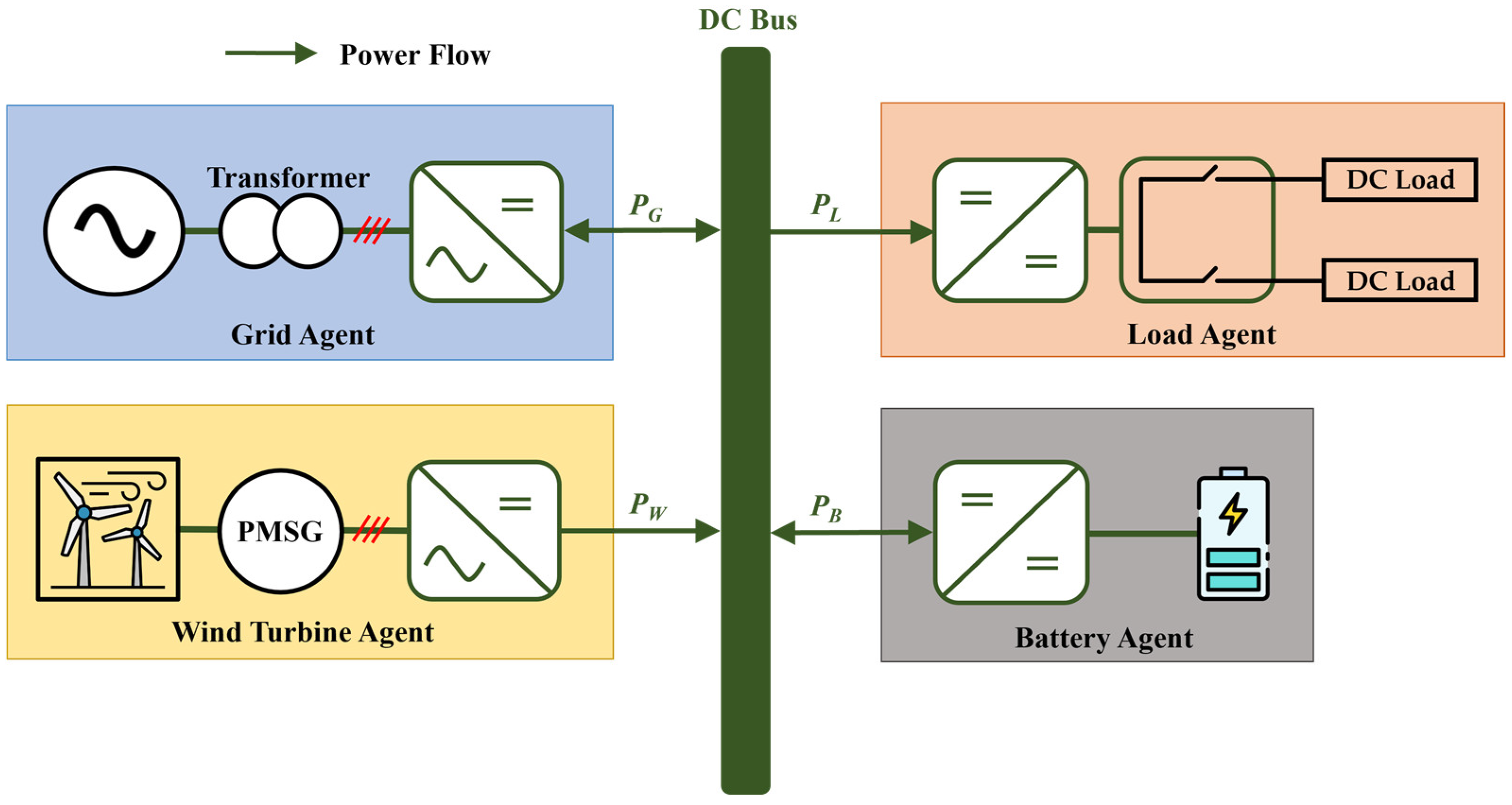
2. System Configuration of a DCMG and Decentralized Control Strategy

A system configuration of a decentralized DCMG is shown in Figure 1. A decentralized DCMG is composed of four power agents: a grid agent, wind turbine agent, load agent, and battery agent. The grid power agent connects the utility grid to the DC bus through a transformer and bidirectional AC–DC converter. The wind turbine power agent connects the wind turbine to the DC bus, in which the mechanical energy is converted into electrical energy via a three-phase permanent magnet synchronous generator (PMSG) and unidirectional AC–DC converter. The battery power agent connects the battery to the DC bus via the bidirectional DC–DC converter. The load agent consists of DC loads directly connected to the DC bus.
In this DCMG system, the battery and grid power agents are capable of transferring bidirectional power, by supplying the power into the DC bus, or absorbing the power from the DC bus. On the other hand, the wind turbine agent only has unidirectional power flow, supplying the power to the DC bus. As shown in Figure 1, P L , P W , P G , and P B represent the power flow of the load, wind turbine, grid, and battery agents. In this paper, positive power values ( + ) represent when the power agent absorbs the power from the DC bus, while negative power values ( ) represent when the power agent supplies the power to the DC bus.
Figure 2 illustrates the simplified structure of the power converter for agent i, which consists of a switch module; an inductor, L i ; a capacitor, C i ; virtual resistance, R L i , for the grid; a wind turbine; and battery agents. In Figure 2, i denotes each agent, i.e., i = G, B, and W, representing the grid, battery, and wind turbine agents, respectively. From Figure 2, the power converter model is derived as follows:
d V D C , i d t = I i o u t C i V D C , i R L i C i
where V D C , i and I i o u t denote the DCV measured from the sensor and converter output current of agent i , respectively. It should be noted that the resistance, R L i , for each power agent, i , is connected in parallel to produce the total equivalent resistance, R L , at the DC bus of the DCMG system. This yields the following relation:
1 R L = 1 R L i
where R L is the total equivalent load.

3. Control Strategy and Transition Operations of Power Agents under Emergency Conditions

3.1. Control Strategy of Power Agents

Figure 3 represents the control block diagram of agent i in the decentralized DCMG system. In this control block diagram, V i r e f denotes the converter reference voltage and d i denotes the converter duty ratio of power agent i. Unlike the conventional droop controllers [30,31], the proposed control strategy only utilizes the primary controller that consists of voltage and current controls to minimize computational burden. The primary controller consists of two cascaded PI controllers for voltage control and current control, as shown in Figure 3. This cascaded structure is quite common and typical in power electronic converters such as the three-phase AC–DC converter or three-phase inverter. Also, to ensure power balance even in emergency conditions, the DCV sensor fault detection algorithm is implemented in agent i , which is described in detail in Section 3.2. For this purpose, the DCV of agent i is estimated by the observer. The estimated DCV is used to detect DCV sensor fault for the purpose of guaranteeing power balance by continuously monitoring DCV sensor failures with the observer even when the DCV sensor operates normally. In addition, by using the estimated DCV value, agent i regulates the DCV using the proportional–integral (PI) controllers. By applying the conventional observer to (1) with the output error, the DCV of agent i can be estimated as follows:
V ^ ˙ D C , i = I i o u t C i V ^ D C , i C i R L i + N i ( V D C , i V ^ D C , i )
where V ^ D C , i is the estimated DCV and N i represents observer gain. To implement the proposed control strategy in both the simulations and experiments, the sampling time was selected as 100 μsec for all power agents to achieve current control. Considering that the current mostly has the fastest dynamics in power converters, and that the sampling time is sufficiently faster than the current dynamics, the influence of the digital control loop delays on voltage regulation and power sharing performance is not as serious as that in the studies in [32,35,38].
To ensure power balance, the decentralized DCMG controller in this study uses nine steady-state operation modes, as shown in Table 1, under normal conditions without any DCV sensor fault. In each operation, the control modes of power agent i are determined according to the criterion that only one power agent regulates the DCV at each instant. When the DCMG system is subject to a change of operation modes caused by uncertainties such as power variation, the transition operation modes are used to identify the power agent that regulates the DCV. The transition operation modes are described in detail in Section 3.3. The control modes of power agent i are separated into voltage control and current control. The voltage control mode implemented as shown in Figure 3 is used to regulate the DCV. In contrast, the current control mode is realized only by the PI current controller.
Nine steady-state operation modes in Table 1 can be explained in detail. In NO1~NO9, the load agent operates in the normal mode, which indicates that the load agent is connected to the DCMG system without load shedding [31,32,39]. In this paper, the electricity price condition is determined via the real-time pricing (RTP) method as an electricity pricing policy [30,31]. While the steady-state operation modes NO1~NO6 represent the grid-connected modes, NO7~NO9 represent the islanded modes when the grid agent is disconnected to the DCMG. The power balance is ensured effectively in both the grid-connected and islanded modes.
Operation NO1: This mode occurs with a high electricity price when the sum of the maximum discharging battery power and wind power is larger than the load. In this case, the grid agent regulates the DCV at a nominal value, Vnom, via GVCMinv (grid agent voltage control mode by inverter operation). The battery agent operates in BCCMdis (battery current control mode by discharging operation), and the wind turbine agent works in maximum power point tracking (MPPT) mode.
Operation NO2: This occurs with a high electricity price when the sum of the maximum discharging battery power and wind power is lower than the load. To guarantee power balance, the grid agent supplies power to the DC bus even with a high electricity price by regulating the DCV at Vnom. The grid agent works in GVCMcon (grid agent voltage control mode by converter operation), the battery agent operates in BCCMdis, and the wind turbine agent works in the MPPT operation.
Operation NO3: This occurs with a normal electricity price when the sum of the maximum charging battery power and load is less than the wind power. To ensure power balance, the grid agent absorbs power from the DC bus by regulating the DCV at Vnom. The grid agent works in GVCMinv, and the battery agent operates in BCCMchar (battery current control mode by charging operation). The wind turbine agent works in the MPPT operation.
Operation NO4: This occurs with a normal electricity price when the sum of the maximum charging battery power and load is higher than the wind power. The grid agent regulates the DCV at Vnom via GVCMcon. The battery and wind turbine agents work in the BCCMchar and MPPT modes.
Operation NO5: This occurs with a normal electricity price when the battery state-of-charge (SOC) level is at the maximum and the wind power is lower than the load. Also, this mode occurs with a high electricity price when the battery SOC level is at its minimum and the wind power is lower than the load. In both situations, the grid agent regulates the DCV at Vnom via GVCMcon while the battery and wind turbine agents work in the IDLE and MPPT modes.
Operation NO6: This occurs with a normal electricity price when the battery SOC level is at its maximum and the wind power is larger than the load. Also, this mode occurs with a high electricity price when the battery SOC level is at the minimum and the wind power is higher than the load. In both cases, the grid agent regulates the DCV via GVCMinv. The battery works in IDLE mode, and the wind turbine works in MPPT mode.
Operation NO7: This occurs in islanded mode (IM) when the wind power is less than the sum of the load and maximum charging power of the battery. The battery agent works in BVCM (battery voltage control mode) to regulate the DCV at Vnom while the wind turbine works in MPPT mode.
Operation NO8: This occurs in IM when the sum of the battery’s maximum charging power and load is lower than the wind power. The wind turbine works in VCM (voltage control mode) to regulate the DCV at Vnom while the battery agent operates in BCCMchar.
Operation NO9: This occurs in IM when the battery SOC level is at its maximum, and the wind power is higher than the load. The wind turbine agent works in VCM and the battery agent operates in IDLE mode.

3.2. Control Strategy under DCV Sensor Fault

Figure 4 represents the DCV sensor fault detection and control mode decision algorithms of agent i under DCV sensor failure. In these algorithms, ei, ε i , c, cmax, V ^ D C , i p r e , I i r e f , and I i , p r e r e f represent the difference between V D C , i and V ^ D C , i , the specified threshold value, the counter value, the specified threshold of the counter, the previous value of V ^ D C , i , the reference current of agent i, and the previous value of I i r e f , respectively. The variable Ffault denotes a fault flag, which is used to indicate the fault in the DCV sensor of agent i . When the DCV sensor has a failure, Ffault is set to one. Otherwise, it is reset to zero. Also, the variable Fmode represents a control mode flag to indicate the operation of agent i before DCV sensor fault. If the operation of agent i is in voltage control before DCV sensor fault, Fmode becomes one. Otherwise, it is reset to zero.
In the proposed strategy, when Ffault is equal to zero, the system compares e i with ε i to investigate the normal operation of the DCV sensor. When e i is larger than ε i , the counter is utilized to count this event. When counter c is less than cmax, counter c increases and V ^ D C , i is replaced with V ^ D C , i p r e . However, if counter c is greater than cmax, the fault detection algorithm confirms DCV sensor failure in power agent i. As soon as DCV sensor fault is identified, the fault detection algorithm sets the fault flag, Ffault, to one. Then, the control mode decision algorithm of agent i is executed to guarantee system stability even under DCV sensor fault by determining a proper operation.
In the control mode decision algorithm, transition operations to current control mode depend on the previous operations of the power agent having DCV sensor failure. If DCV sensor failure occurs in the power agent that does not regulate the DCV, it still maintains the operation of the current control mode, with the current reference being as follows:
I i r e f = I i , p r e r e f
On the other hand, if DCV sensor failure happens in power agent i, which regulates the DCV, the other power agent should take the role of regulating the DCV. For this purpose, the power agent operation is shifted to current control mode with the reference current change. In case DCV sensor fault occurs in the grid or battery agent that regulates the DCV, the grid or battery agent changes its operation mode to current control mode, with the current reference being as follows:
I i r e f = I i , p r e r e f δ i
Because more power is supplied to the DC bus, the DCV level is continuously increased. As a result, by detecting this DCV transition, remaining power agents can regulate the DCV after the transition operation mode. In case DCV sensor fault occurs in the wind turbine agent that regulates the DCV, the wind turbine agent changes its operation mode to current control mode, with the current reference being as follows:
I W r e f = I W , p r e r e f + δ W
Because the power supplied to the DC bus is reduced, the DCV level decreased. By detecting this DCV transition, remaining power agents can regulate the DCV after the transition operation mode.
To ensure both power balance and voltage regulation under DCV sensor fault, Table 2 shows additional steady-state operation modes for a decentralized DCMG system according to the DCV sensor fault. During normal operation without any failure, the DCMG operates in one of the steady-state operation modes listed in Table 1. Under DCV sensor failure, the DCMG operation is changed to one of additional the steady-state modes in Table 2 after the transition operations, which will be explained in the next subsection.
Nine additional steady-state operation modes in Table 2 are explained in detail. The operation mode transition from the normal operation in Table 1 to the additional operation in Table 2, caused by the DCV sensor faults, will be described in Figure 5. Similarly to the fact that the DC bus voltage is always regulated by at least one power agent in steady-state operation modes NO1~NO9 in Table 1, it is also regulated by at least one power agent in AO1~AO9 in Table 2.
Operation AO1: In this mode, because DCV sensor fault occurs in the grid, the grid operates in GCCMinv (grid current control mode by inverter operation), and the battery operates in BVCM to regulate DCV at Vnom. The wind turbine operates in MPPT mode.
Operation AO2: In this mode, because the DCV sensor fault occurs in both the grid and battery, the battery operates in BCCMdis and the grid operates in GCCMinv. The wind turbine operates in VCM to regulate the DCV at Vnom.
Operation AO3: The battery agent operates in BVCM to regulate the DCV at Vnom. The wind operates in MPPT mode and the grid agent operates in GCCMcon (grid current control mode by converter operation).
Operation AO4: The wind turbine operates in VCM to regulate the DCV at Vnom. The battery operates in BCCMdis and the grid operates in GCCMcon.
Operation AO5: The wind turbine operates in VCM to regulate the DCV at Vnom. The battery operates in BCCMchar and the grid operates in GCCMinv.
Operation AO6: The wind turbine operates in VCM to regulate the DCV at Vnom. The battery operates in BCCMchar and the grid operates in GCCMcon.
Operation AO7: The wind turbine operates in VCM to regulate the DCV at Vnom. The battery operates in IDLE mode and the grid operates in GCCMcon.
Operation AO8: The wind turbine operates in VCM to regulate the DCV at Vnom. The battery operates in IDLE mode and the grid operates in GCCMinv.
Operation AO9: The wind turbine operates in VCM to regulate the DCV at Vnom. The battery operates in BCCMdis.
Figure 5 shows operation mode transitions caused by DCV sensor failure, in which the DCV sensor faults of the battery, wind turbine, and grid are denoted by the variables F B , F W , and F G , respectively. The maximum and minimum SOC levels of the battery agent are denoted by S O C B H and S O C B L , respectively. The variables F B , F W , and F G are represented as follows:
F i = 1 ,   if DCV sensor failure happens in power agent   i F i = 0 ,   otherwise , for   i = B ,   W ,   G .
Similarly, two variables to denote the battery SOC status are defined as follows:
F B H = 1 ,   if   S O C B =   S O C B H ; F B H = 0 ,   otherwise ;
F B L = 1 ,   if   S O C B =   S O C B L ; F B L = 0 ,   otherwise
where S O C B denotes the battery SOC.
If DCV sensor failures occur during normal operation NO1, the DCMG is changed to additional operation modes as represented in Figure 5a. During the operation of NO1, if DCV sensor failure happens in the battery (FB = 1) or wind turbine (FW = 1) or both the wind turbine and battery ((FW = 1) and (FB = 1)), the DCMG system still maintains in NO1 because the wind turbine and battery do not regulate the DCV before sensor fault. If the grid (FG = 1) or both the grid and wind turbine ((FG = 1) and (FW = 1)) have DCV sensor fault, the DCMG system is changed to mode AO1. The grid agent changes the control mode from GVCMinv in NO1 to GCCMinv in AO1 according to Figure 4. In this situation, the battery operates in BVCM to regulate the DCV. Finally, if both the grid and battery agents ((FG = 1) and (FB = 1)) have DCV sensor fault, only the wind turbine can regulate the DCV. Therefore, the DCMG system is changed to mode AO2.
Figure 5b–d show the transition to additional operation modes of the DCMG when DCV sensor failure occurs during normal DCMG system operation in NO2, NO3, and NO4, respectively. These figures show similar behavior with that shown in Figure 5a according to the location of DCV sensor failure. However, under each DCV sensor fault, the destination of additional operation modes is quite different. In the normal operation modes NO2, NO3, and NO4, the grid agent regulates the DCV either in converter or inverter operation. Even in the case of (FB = 1), (FW = 1) or ((FB = 1) and (FW = 1)), the DCMG system still maintains the previous operations, NO2, NO3, and NO4, respectively, as in Figure 5b–d, because the grid agent can still regulate the DCV. If DCV sensor failure happens in the grid, (FG = 1) or ((FG = 1) and (FW = 1)), DCV regulation is achieved by the battery agent, which results in a transition into additional operation modes AO3, AO1, and AO3, as shown in Figure 5b–d, respectively. If the failure of the DCV sensor happens in the grid and battery at the same time ((FG = 1) and (FB = 1)), only the wind turbine is able to regulate the DCV. Then, via a transition into additional operation modes AO4, AO5, and AO6, the wind turbine regulates DCV in VCM, and other agents operate in current control mode.
Figure 5e represents the operation mode transition from NO5 due to DCV sensor faults. As we mentioned before, NO5 occurs with a normal electricity price when the battery SOC level is at the maximum, and the when the wind power is lower than the load. Also, this mode occurs with a high electricity price when the battery SOC level is at the minimum, and when the wind power is lower than the load. If DCV sensor failure does not occur in the grid, the DCMG maintains mode NO5. In the condition [(FBH = 1)&(FG = 1)] or [(FG = 1)&(FB = 1)], the DCMG is changed from NO5 to AO7. In the first condition, the battery operates in IDLE mode because it can not absorb charging power. In the second condition, because the battery and grid can not regulate DCV, the wind turbine operates in VCM to regulate DCV, which results in AO7. In the condition of [(FBL = 1)&{(FG = 1) or ((FG = 1)&(FW = 1))}], the DCMG system is changed from NO5 to AO3. This condition represents the case in which DCV sensor failure happens in the grid, or in both the grid and wind turbine agents when the battery SOC level is at the a minimum. In either case, the battery works in BVCM to regulate the DCV with charging, which results in AO3.
Figure 5f has a similar structure to Figure 5e. While the grid agent starts with GVCMcon in the normal operation mode NO5 in Figure 5e, it starts with GVCMinv in NO6 in Figure 5f. Unless DCV sensor failure occurs in the grid, the DCMG maintains NO6. Depending on the battery’s SOC condition and the DCV sensor fault locations, this normal operation mode is shifted to AO8 or AO1, respectively. In AO1, the battery agent regulates the DCV in BVCM. If the battery is not available to regulate the DCV because of the SOC condition or DCV sensor failure, the wind turbine is used in VCM, instead.
Figure 5g shows the operation mode transition caused by the DCV sensor faults when the DCMG works in NO7. If the DCV sensor in the battery is operating normally regardless of whether DCV sensor failure occurs in the wind turbine or grid, the DCMG maintains NO7. However, when the battery has a DCV sensor failure, i.e., (FB = 1), only the wind turbine can regulate the DCV in VCM. Then, the DCMG system is changed to AO9 or NO8 depending on the relation of the wind power and load.
Figure 5h represents transition of the DCMG system when DCV sensor failure occurs during the normal operation NO8. Unless DCV sensor failure occurs in the wind turbine, the DCMG maintains NO8. If the wind turbine has a DCV sensor failure (FW = 1), the battery agent regulates the DCV in BVCM, which results in the change of the DCMG operation to NO7.
Finally, Figure 5i represents the operation transition from NO9 caused by DCV sensor failure. Since only the wind turbine is operating in NO9, the DCMG maintains NO9, if the DCV sensor of the wind turbine does not have a fault.

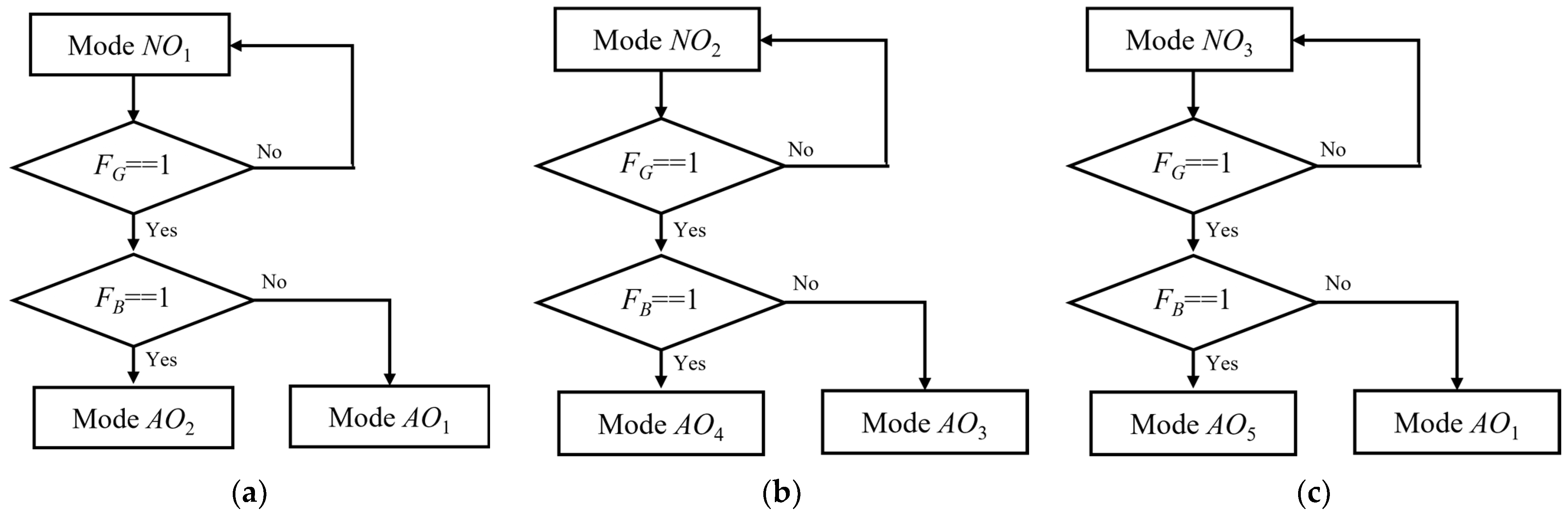
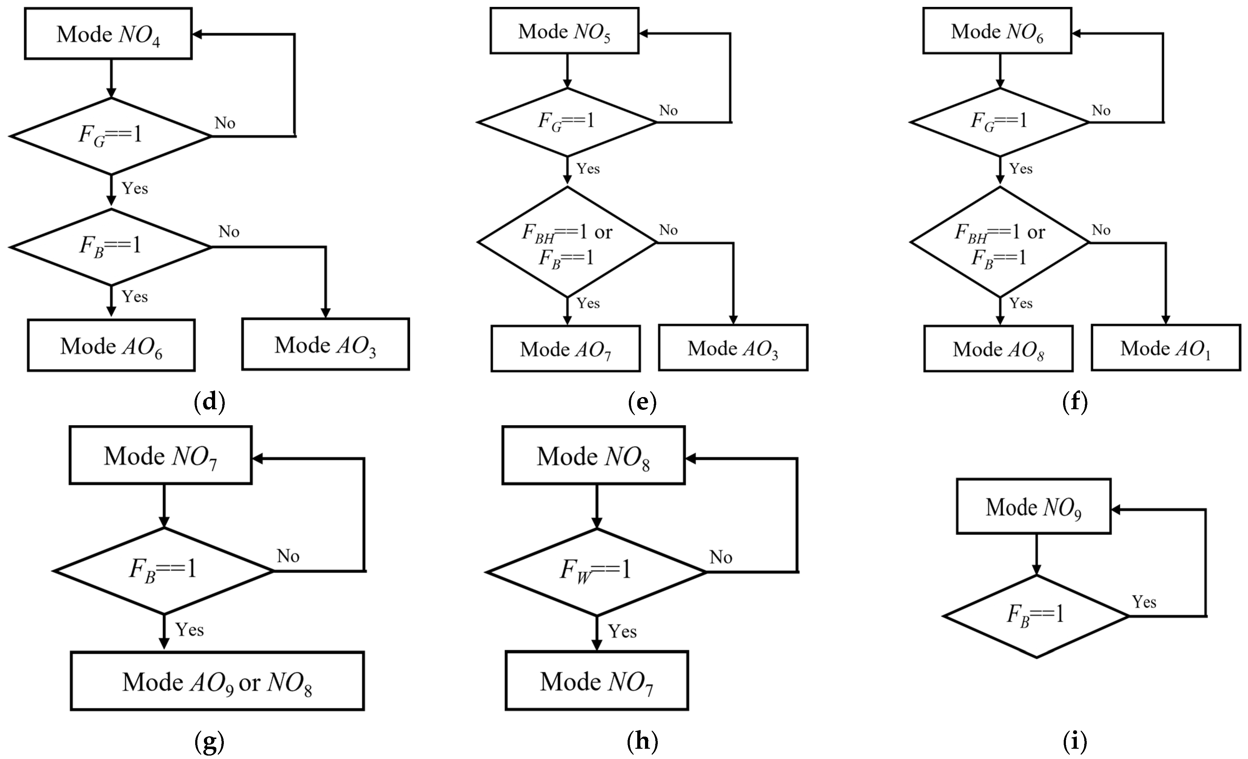
3.3. Transitional Operation Modes in Power Agents

In the proposed method, all power agents in the DCMG determine the operation modes by detecting the information of the DCV level without DCLs. When certain transient conditions are introduced into the DCMG, the agents of the DCMG system temporarily shifts the DCV value to different levels during a predetermined period. During this predetermined time, all the power agents appropriately change the operation mode during the transient periods before the DCMG system returns to another steady-state operation mode.
Table 3 lists the transition operation modes that are introduced into the DCMG system due to DCMG system uncertainty. This table also shows the power agents that activate each transition operation mode and resultant actions. In this table, VL1, VL2, and VL3 denote the first, second, and third low-level DCV, respectively, and VH1, VH2, and VH3 denote the first, second, and third high-level DCV, respectively.
When an event occurs such as the electricity price changing from normal to high, or grid agent reconnection from a fault with a high electricity price happens, the DCMG system temporarily uses the transition operation mode TO1. In TO1, the grid agent regulates the DCV to VL1 to inform other power agents of this event. Figure 6 shows the detection of the transition operation modes by the power agent. In Figure 6, the horizontal axis represents the time required for transition operation detection, the vertical axis represents the DCV levels for different transition operations, and the color indicates the power agents that detect the transition operation. As the DCV level reaches VL1, and lasts for 0.1 s, the other power agents such as the battery, wind turbine, and load agent identify this event, and change their operation appropriately. After 0.5 s from the instant that the DCV reaches VL1, the grid regulates the DCV back to Vnom.
When an event occurs such as a change in the electricity price from high to normal, or when the reconnection of the grid agent from a fault with a normal electricity price happens, the DCMG system temporarily uses the transition operation mode TO2. In TO2, the grid regulates the DCV to VH1 to inform other power agents of this event. As shown in Figure 6, as the DCV level reaches VH1, and lasts for 0.1 s, the other power agents identify this event, and change their operation appropriately. After 0.6 s from the instant that the DCV reaches VH1, the grid agent regulates the DCV back to Vnom.
In the IM of the DCMG system, if the battery is in critical condition, such as when it has a maximum battery SOCB, the DCV increases since the battery cannot absorb power. After the DCV reaches VH3, the wind turbine agent maintains the DCV at VH3 for 0.3 s with the transition operation mode TO3. After 0.01 s from the instant that the DCV reaches VH3, the battery agent identifies this event to change the operation appropriately. After 0.3 s, the wind turbine agent regulates the DCV to Vnom again. This transition operation mode, TO3, is also initiated by the grid when the grid operating in GVCMinv is disconnected from the DCMG system, or when the grid agent has a DCV sensor fault.
The transition operation mode TO4 is triggered by the grid when the grid operating in GVCMcon has a fault. The transition operation mode TO4 is also activated when the wind power is decreased in IM. In this situation, since the supply power is smaller than the load, the DCV decreases. If the battery agent detects that the DCV level is kept lower than VL2 for more than 0.01 s, as shown in Table 3, the battery agent acknowledges this event. Then, the battery changes operation to BVCM to regulate the DCV back to Vnom.
When the grid agent is in emergency conditions such as a grid fault under a high electricity price or DCV sensor fault, the DCV increases due to surplus power, which triggers the transition operation mode TO5. As the DCV level is kept higher than VH2 for more than 0.01 s, the battery agent acknowledges this event, and changes operation to BVCM to regulate the DCV back to Vnom.
When SOCB reaches the minimum level and the wind generation power is smaller than the load demand in the islanded DCMG, the DCV is decreased to the critical value of VL3. After 0.01 s from the instant the DCV reaches VL3, load shedding starts.

4. Simulation Tests

In this section, the reliability and feasibility of the proposed strategy are evaluated through simulation tests by using PSIM tools. The simulations are conducted considering several uncertain operating conditions such as DCV sensor fault, grid fault, minimum or maximum battery SOC, agent power variation, and electricity price change in the grid. System parameters of a decentralized DCMG are shown in Table 4. In this table, PMSG denotes a permanent magnet synchronous generator, and the LCL filter represents the filter composed of an inductor, capacitor, and inductor.

4.1. Transition from Grid-Connected Mode to IM under DCV Sensor Fault

Figure 7 represents simulation test results for when the DCMG undergoes a transition from grid-connected mode to IM, and the battery has DCV sensor failure. In Figure 7, V ^ D C , i (for i = G, W, and B) is the estimated DCV value in the power agent, V D C , i s e n s o r is the DCV measured by the sensor in the power agent, and V D C r e a l is the actual DCV value. In this simulation test, the DCMG starts in NO4, which is one of the GCMs. In this mode, the grid operates in GVCMcon to regulate the DCV at Vnom, the battery operates in BCCMchar, and the wind turbine agent operates in MPPT mode. At t = 0.5 s, grid fault occurs, which causes the change of the DCMG system operation from GCM NO4 to IM TO4. Since the supplied power is smaller than the load, the DCV is reduced. If the battery agent detects that the DCV level is kept lower than VL2 for more than 0.01 s, as shown in Table 3, the battery acknowledges grid disconnection from the DCMG. Then, the battery changes operation from BCCMchar to BVCM to regulate the DCV back to Vnom, and the entire DCMG system operation is changed from TO4 to NO7.
At t = 1.2 s, when the DCV is regulated by the battery, battery DCV sensor fault occurs. As soon as the battery agent identifies DCV sensor failure, it is shifted to current control mode by the proposed fault detection and control mode decision algorithms shown in Figure 4. By using the proposed strategy, the battery agent increases the DCV by supplying more power to the DC bus. If the DCV level reaches VH3, the wind turbine agent maintains the DCV to VH3 for 0.3 s. Eventually, the DCMG is changed from NO7 to TO3. After 0.3 s from the instant that the DCV reaches VH3, the wind turbine agent regulates the DCV back to Vnom and subsequently the DCMG system operation is changed from TO3 to AO9.
This simulation test confirms that the battery agent can still supply power to the DC bus in current control mode even if the battery has a DCV sensor failure, which clearly demonstrates that the proposed control strategy ensures power sharing and seamless power management even in abnormal system conditions.

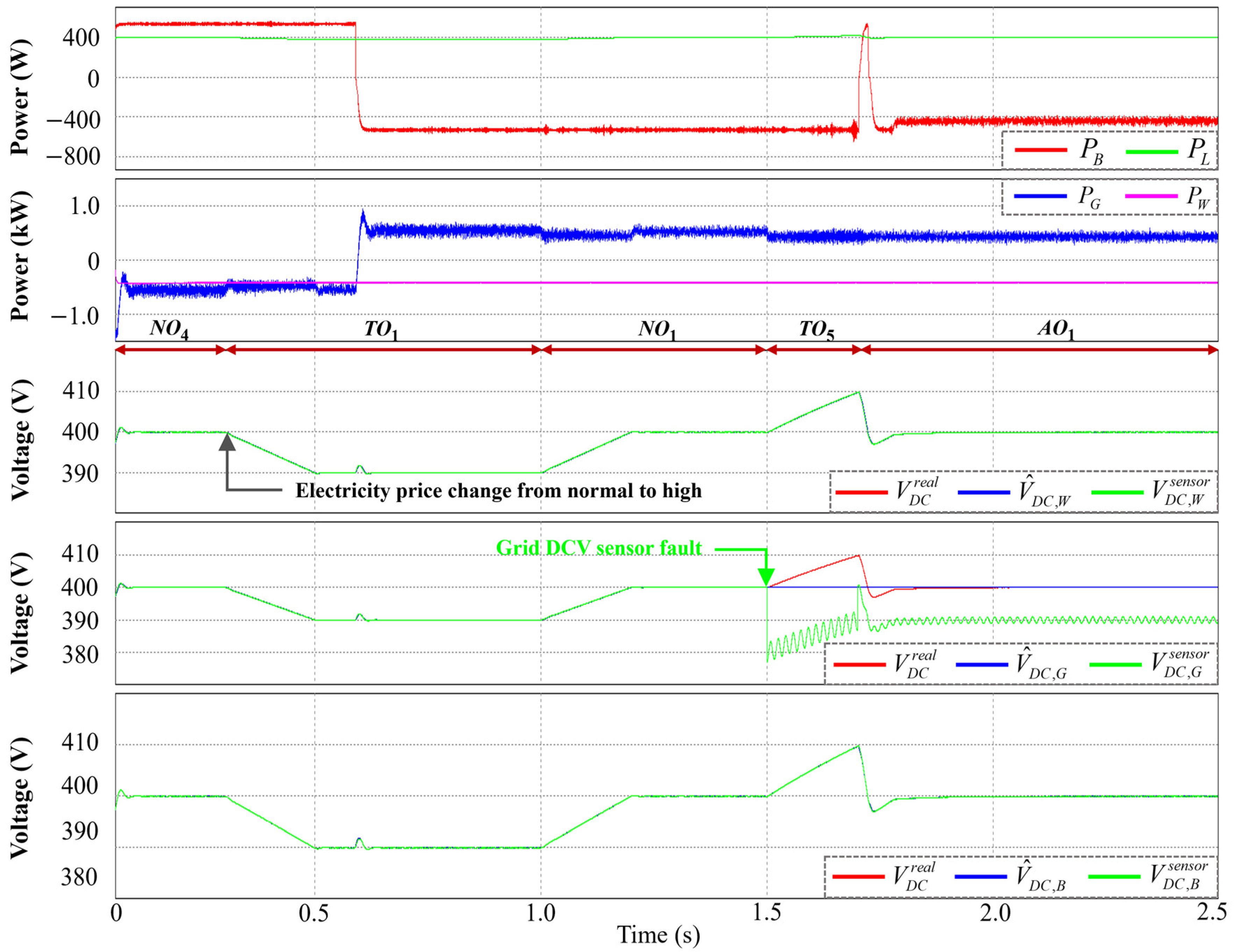
4.2. Transition from Normal to High Electricity Price Conditions under DCV Sensor Fault

Figure 8 represents simulation test results for when the electricity price changes from normal to high under grid DCV sensor failure. The DCMG initially works in NO4 with a normal electricity price. In this mode, the grid operates in GVCMcon to regulate the DCV at Vnom, the battery operates in BCCMchar, and the wind turbine operates in MPPT mode. At t = 0.3 s, when the electricity price is changed from normal to high, the grid agent regulates the DCV to VL1 in order for the other agents to recognize the electricity price change. Then, the DCMG is changed from NO4 to TO1. After 0.1 s from the instant that the DCV reaches VL1, the wind turbine and battery detect this event. Then, the battery changes operation from BCCMchar to BCCMdis to inject power to the DC bus, which causes the grid to change from GVCMcon to GVCMinv. After 0.5 s from the instant that the DCV reaches VL1, the grid regulates the DCV back to Vnom, and the entire DCMG operation is changed from TO1 to NO1.
At t = 1.5 s, when grid DCV sensor fault occurs, the grid operation is changed to current control mode as soon as DCV sensor failure is detected, as shown in Figure 4. After that, the DCMG system is changed from NO1 to TO5. According to the proposed fault detection and control mode decision algorithms, the grid agent increases the DCV by injecting more power to the DC bus. When the battery detects that the DCV level is kept higher than VH2 for more than 0.01 s, the battery recognizes the DCV sensor fault in the grid. Then, the battery changes operation from BCCMdis to BVCM to regulate the DCV back to Vnom, and the DCMG is changed from TO5 to AO1. This simulation test result also validates continuous power sharing in the presence of failure in the grid DCV sensor.

4.3. Grid Recovery with High Electricity Price Condition under DCV Sensor Fault

Figure 9 represents the simulation test results in the case of grid reconnection at a high electricity price under wind DCV sensor failure. The DCMG is assumed to start in NO7, which is one of the IMs. In this mode, the battery works in BVCM to regulate the DCV at Vnom, and the wind turbine operates in MPPT mode. At t = 0.5 s, DCV sensor failure occurs in the wind turbine. However, the DCMG system maintains mode NO7 since the wind turbine does not regulate the DCV. In this circumstance, the wind turbine continues operating in MPPT mode with I W r e f = I W , p r e r e f , as explained in Figure 4.
At t = 1.0 s, when the grid agent reconnects at a high electricity price, the grid works in GVCMinv to regulate the DCV to VL1, and the DCMG is changed from NO7 to TO1. After 0.1 s from the instant that the DCV reaches VL1, the wind turbine and battery detect grid reconnection at a high electricity price. Then, the battery changes operation from BVCM to BCCMdis to supply the power to the DC bus. After 0.5 s from the instant that the DCV reaches VL1, the grid regulates the DCV back to Vnom, and the entire DCMG operation is changed from TO1 to NO1. This simulation result also proves the occurrence of continuous power sharing under DCV sensor failure in the wind turbine.

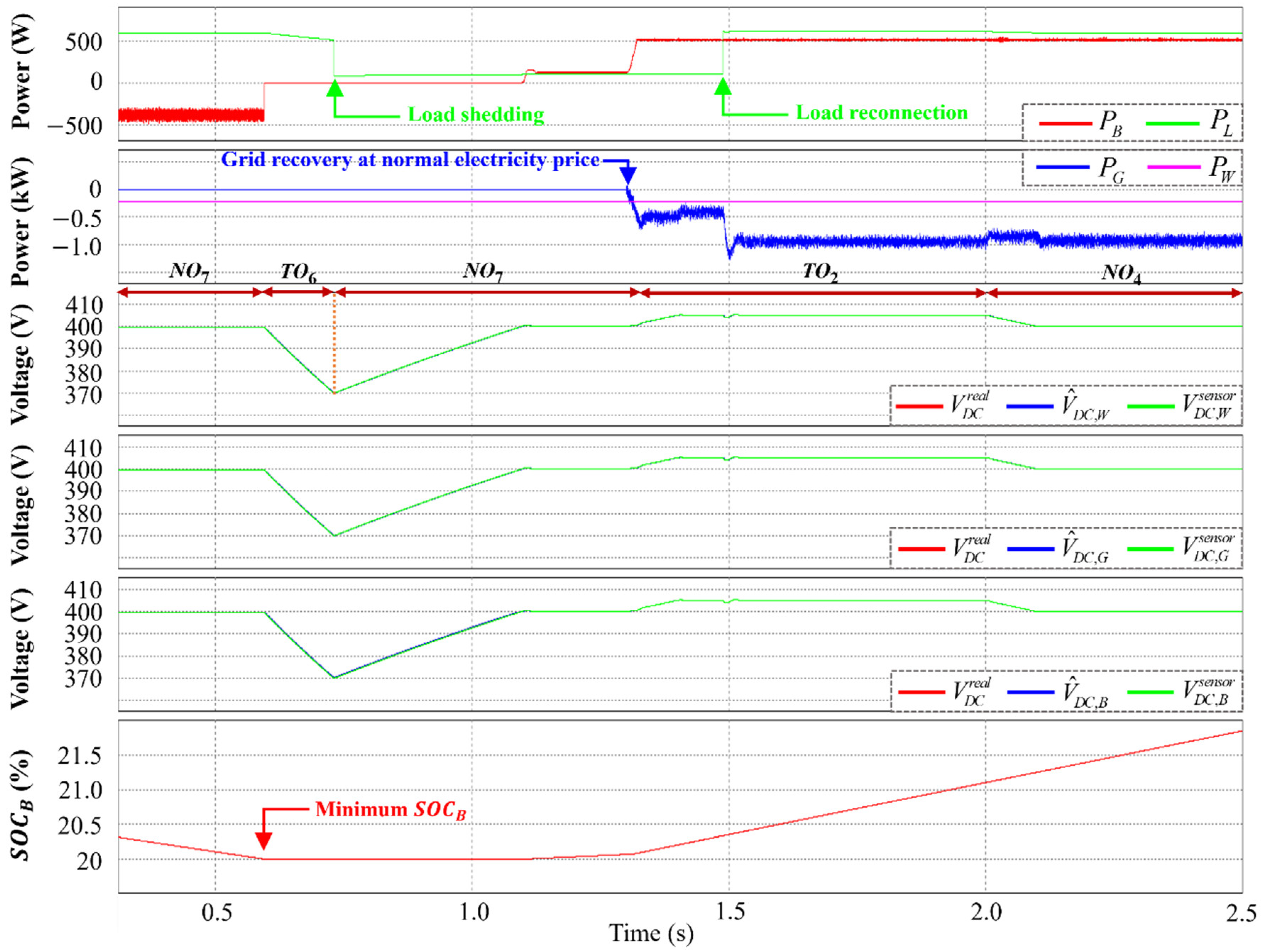
4.4. Transition of Electricity Price Condition from High to Normal under DCV Sensor Fault

Figure 10 represents simulation test results for when the electricity price changes from high to normal under battery and grid DCV sensor faults. In this simulation, the DCMG initially operates at NO1 with a high electricity price. The grid agent operates in GVCMinv to regulate the DCV at Vnom, the battery agent operates in BCCMdis, and the wind turbine operates in MPPT mode.
At t = 0.3 s, when the electricity price changes from high to normal, the grid agent regulates the DCV to VH1, and the DCMG system is changed from NO1 to TO2. After 0.1 s from the instant that the DCV reaches VH1, the wind turbine and battery detect the change in electricity price. Then, the battery agent changes operation from BCCMdis to BCCMchar to absorb power from the DC bus, which causes the grid to change operation from GVCMinv to GVCMcon. After 0.6 s from that instant the DCV reaches VH1, the grid regulates the DCV back to Vnom, and the DCMG is changed from TO2 to NO4.
At t = 1.4 s, DCV sensor failure occurs in the battery. The DCMG maintains NO4 because the battery does not regulate DCV. In this case, the battery agent maintains the previous operation BCCMchar with I B r e f = I B , p r e r e f as shown in Figure 4.
At t = 1.7 s, DCV sensor failure happens in the grid that is regulating the DCV to Vnom. When the grid agent detects DCV sensor failure, the grid operation is instantly shifted to current control mode by the proposed scheme, which changes the DCMG operation from NO4 to TO3. The grid agent increases the DCV by injecting larger power into the DC bus. If the battery agent detects that the DCV level is kept higher than VH2 for more than 0.01 s, the battery agent acknowledges the grid DCV sensor fault. However, the battery cannot regulate the DCV due to DCV sensor failure. In this case, the DCV level further increases to more than VH2. As the DCV reaches VH3, the wind turbine instantly maintains the DCV at VH3 for 0.3 s. After 0.3 s from the instant that the DCV reaches VH3, the wind turbine regulates the DCV back to Vnom, and the entire DCMG operation is changed from TO3 to AO6. This simulation test shows that the proposed scheme ensures uninterruptible power management even in circumstances of multiple failures in a DCV sensor.

4.5. Case of Minimum Battery SOC Level

Figure 11 represents simulation test results for load shedding when the battery SOC level reaches the minimum. The DCMG starts in NO7, which is one of the IMs. In this mode, the wind power is smaller than the load, which causes the battery to operate in BVCM by discharging to maintain the DCV at Vnom.
At t = 0.6 s, when the battery SOC level drops to the minimum value, the battery changes operation from BVCM to IDLE mode, and the DCMG is changed from NO7 to TO6. Since the power supply is smaller than the load, the DCV drops rapidly. If the load agent detects that the DCV level is kept lower than VL3 for more than 0.01 s, as shown in Table 3, the load agent recognizes that the supplied power is less than the load. Consequently, load shedding is activated to prevent DCMG system collapse in these emergency conditions. When the DCV becomes higher than Vnom because of load shedding, the battery operation is changed from IDLE mode to BVCM to regulate the DCV back to Vnom, which changes the DCMG operation from TO6 to NO7.
At t = 1.3 s, as the grid agent is reconnected to the DCMG system with a normal electricity price, the grid operates in GVCMcon to regulate the DCV to VH1, and the DCMG operation is changed from NO7 to TO2. After 0.1 s from the instant that the DCV reaches VH1, the wind turbine, load, and battery recognize grid reconnection with a normal electricity price. Consequently, the battery changes operation from BVCM to BCCMchar and load reconnection starts. After 0.6 s from the instant that the DCV reaches VH1, the grid regulates the DCV back to Vnom, and the entire DCMG operation is changed from TO2 to NO4.

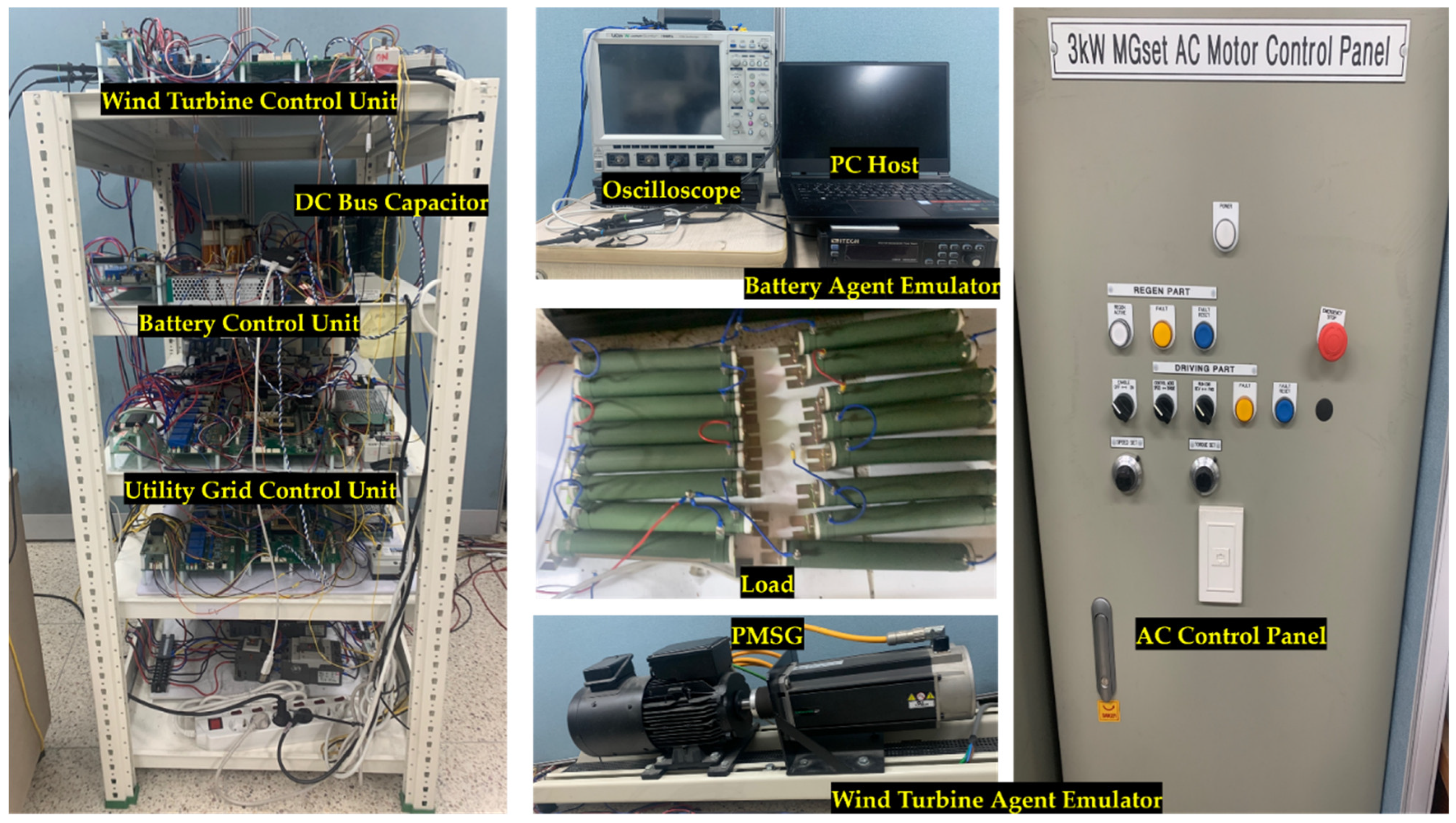
5. Experimental Results

An experimental hardware setup of the decentralized DCMG that is depicted in Figure 12 is utilized to confirm the feasibility and reliability of the proposed strategy. To construct a decentralized DCMG, four power agents, which are the wind turbine, grid, battery, and load agents, are used with the system parameters in Table 4. The wind turbine agent is constructed with a unidirectional AC–DC converter and wind turbine emulator that is composed of a PMSG, a mechanically coupled induction motor, and an AC motor control panel. The battery agent employs an interleaved bidirectional DC–DC converter to connect the battery with the DC bus. The grid agent is composed of a bidirectional AC–DC converter, main grid, and a Y-Δ transformer. A digital signal processor, TMS320F28335, is used to realize the proposed strategy. The experimental tests are conducted under five different conditions: change in electricity price from normal to high, DCV sensor failure in GCM, transition from grid-connected mode to IM, minimum SOCB level in IM, and DCV sensor fault in IM.

5.1. Transition of Electricity Price from Normal to High in GCM

Figure 13 represents the experimental tests in the case that the electricity price changes from high to normal in GCM. The DCMG system starts in NO5, which is one of the GCMs, and SOCB is at the maximum level. The grid operates in GVCMcon to regulate the DCV to Vnom, the wind turbine works in MPPT mode, and the battery works in IDLE mode.
When the electricity price changes from normal to high, the grid regulates the DCV to VL1 in order for the other agents to recognize the change in electricity price. Consequently, the DCMG operation is changed from NO5 to TO1. After 0.1 s from the instant that the DCV reaches VL1, the wind turbine and battery detect the change in electricity. Then, the battery changes the operation from IDLE mode to BCCMdis to supply power to the DC bus, which makes the grid change operation from GVCMcon to GVCMinv. After 0.5 s from the instant the DCV reaches VL1, the grid regulates the DCV back to Vnom, and the entire DCMG operation is changed from TO1 to NO1. This experimental result clearly shows voltage stabilization and good power balance using the decentralized control method without any DCLs.

5.2. GCM under DCV Sensor Fault

Figure 14 represents the experimental test for GCM under grid and battery DCV sensor faults. In this test, the DCMG system initially operates in NO4 with a normal electricity price. In this mode, the grid operates in GVCMcon to regulate the DCV at Vnom, while the battery and wind turbine operate in BCCMchar and MPPT mode.
When a DCV sensor fault happens in a battery, the DCMG system stays in NO4 because the battery does not regulate the DCV. In this situation, the battery operation is still BCCMchar with I B r e f = I B , p r e r e f , as shown in Figure 4. When the grid agent that is regulating the DC bus has a sensor failure, the grid operation mode is changed to GCCMcon, and the DCMG system operation is changed from NO4 to TO3. Similar to what is shown in Figure 10, the DCV increases rapidly in this case since the grid supplies larger power to the DC bus. If the battery agent detects that the DCV level is kept higher than VH2 for more than 0.01 s, the battery agent acknowledges grid DCV sensor fault. However, the battery cannot regulate the DCV due to DCV sensor failure. In this case, the DCV level further increases to more than VH2. As the DCV reaches VH3, the wind turbine instantly operates in VCM to maintain the DCV at VH3. After 0.3 s from the instant that the DCV reaches VH3, the wind turbine regulates the DCV back to Vnom, and the DCMG operation is changed from TO3 to AO6. This experimental test shows the same behaviors as those in the simulation in Figure 10, which verifies that the proposed control strategy achieves both voltage stabilization and power balance even under multiple failures in DCV sensors.

5.3. Transition between GCM and IM

Figure 15 shows the experimental test for the transition from GCM to IM. The DCMG operates in NO4, which is one of the GCMs. The grid operates in GVCMcon to regulate the DCV to Vnom, while the battery and wind turbine operate in BCCMchar and MPPT mode.
When the grid is disconnected from DCMG, it causes a change of DCMG operations from GCM NO4 to IM TO4. The DCV decreases rapidly since the power supply is smaller than the power demand. If the battery detects that the DCV level is kept lower than VL2 for more than 0.01 s, the battery acknowledges grid disconnection from the DCMG system. Then, the battery changes operation from BCCMchar to BVCM to regulate the DCV back to Vnom, and the entire DCMG system operation is changed from TO4 to NO7.

5.4. Test with IM under Minimum Battery SOC Level

Figure 16 shows the experimental test for load shedding when the battery SOC level reaches the minimum value. The DCMG starts in NO7, which is one of the IMs. In this mode, the battery supplies power to the DC bus to regulate the DCV in BVCM since the wind power is smaller than the load. When the battery SOC level reaches the minimum value, the battery changes the operation from BVCM to IDLE mode, and the DCMG is changed from NO7 to TO6. The DCV is decreased rapidly because the power supply is smaller than the power demand. After 0.01 s from the instant that the DCV is lower than VL3, the load agent detects that the power supply is smaller than the demand, and then load shedding is activated to prevent DCMG system collapse for such an emergency condition. When the DCV becomes higher than Vnom, because the power supply is higher than the demand, the battery operation is changed from IDLE mode to BVCM to regulate the DCV back to Vnom, which changes the DCMG system from TO6 to NO7.

5.5. Test with IM under DCV Sensor Fault

Figure 17 shows the experimental test for the IM under battery DCV sensor failure. Initially, the DCMG system starts in NO7, which is one of the IMs. In this mode, the battery supplies power to the DC bus to regulate the DCV in BVCM since the wind power is smaller than the load. When battery DCV sensor fault occurs, the battery identifies DCV sensor failure. Then, the battery changes the operation to current control mode. By using the proposed scheme, the battery increases the DCV, and the DCMG is changed from NO7 to TO3. When the DCV reaches VH3, the wind turbine regulates the DCV to VH3 in VCM. After 0.3 s from the instant that the DCV reaches VH3, the wind turbine regulates the DCV back to Vnom, and the DCMG operation is changed from TO3 to AO9.

6. Conclusions

This study proposed a continuous power management strategy for a decentralized DCMG based on transitional operation modes under system uncertainty and sensor failure. The power agents connected in the decentralized DCMG utilize only a primary controller to achieve both voltage regulation and power sharing with reduced computational burden. To improve the reliability of DCMG operation, the abnormality of the DCV sensor is monitored by the proposed DCV sensor fault detection algorithm, in which all the power agents estimate the DCV by using the observer and compare the estimated DCV with the measured DCV. If a power agent detects the failure of the DCV sensor, it modifies the operational mode appropriately to ensure the stability of the DCMG in accordance with the proposed control mode decision algorithm under the DCV sensor fault. The proposed algorithms can maintain the operation of the DCMG system without system collapse even with multiple sensor failures, if only one sensor operates normally.
To achieve continuous power balance as well as voltage stabilization even under several uncertainty conditions such as power variation in distributed generation, sudden grid disconnection, and critical battery status, the DCMG system uses the transitional operation modes to transmit the proper information to other power agents without using DCLs in this study. In the transitional operation modes, the DCV levels are temporarily shifted to an appropriate level during the predetermined period. Based on the DCV levels, each power agent determines its operation mode after detecting the uncertain conditions. The effectiveness and reliability of the proposed control strategy were demonstrated via various simulation and experimental tests under several test conditions. In summary, the experimental tests clearly demonstrated that DCV regulation could be achieved rapidly even under uncertain conditions. In the experimental tests, when multiple DCV sensor faults occurred, the transition time to restore the DCV to its nominal value was 1.6 s under the proposed strategy. In the grid fault condition, the DCV was restored in 1.0 s. In addition, when the battery reached the minimum SOC level, the transition time to restore the DCV to its nominal value was 1.8 s. In the case of DCV sensor failure in islanded mode, the transition time was 1.9 s.

Author Contributions

The primary idea for the structure of the DC microgrid and the entire system were developed by S.-B.J., D.T.T., M.A.M.J., M.K. and K.-H.K. The research was conducted and numerical data were analyzed by S.-B.J., D.T.T. and M.A.M.J. under the guidance of K.-H.K., S.-B.J., D.T.T., M.A.M.J., M.K. and K.-H.K., who worked together in preparing the manuscript. All authors have read and agreed to the published version of the manuscript.

Funding

This study has been conducted with the support of the Korea Institute of Industrial Technology as “Development of core technologies of AI based self-power generation and charging for next-generation mobility (KITECH EH-24-0003)”.

Institutional Review Board Statement

Not applicable.

Informed Consent Statement

Not applicable.

Data Availability Statement

Data are contained within the article.

Conflicts of Interest

The authors declare no conflicts of interest.

Abbreviations

ACMGAC microgrid
BCCMcharBattery current control mode by charging operation
BCCMdisBattery current control mode by discharging operation
BVCMBattery voltage control mode
DCMGDC microgrid
DCLDigital communication line
DCVDC bus voltage
ESSEnergy storage system
GCCMconGrid agent current control mode by converter operation
GCCMinvGrid agent current control mode by inverter operation
IMislanded mode
LCLInductive–Capacitive–Inductive
MPPTPermanent magnet synchronous generator
PIProportional–integral
PMSGPermanent magnet synchronous generator
PVPhotovoltaic
SOCState of charge
VCMVoltage control mode of wind turbine
AOmAdditional steady-state operation mode, m = 1, 2, 3,…,9
cCounter
CiCapacitor of agent i
cmaxSpecified threshold of the counter
δ i Small positive value of agent i
e i Difference between VDC,i and V ^ D C , i
ε i Specified threshold value
FBFlag variable to denote the DCV sensor failure in battery agent
FWFlag variable to denote the DCV sensor failure in wind turbine agent
FGFlag variable to denote the DCV sensor failure in grid agent
FmodeControl mode flag
FfaultFault flag
I i o u t Converter output current of agent i
I i r e f Reference current of agent i
I i , p r e r e f Previous value of I i r e f
LiInductor of agent i
NOmNormal operation mode, m = 1, 2, 3,…,9
NiObserver gain
PBPower flow of the battery agent
PGPower flow of the grid agent
PLPower flow of the load agent
PWPower flow of the wind turbine agent
RLTotal equivalent resistance
RLiVirtual resistance of agent i
SOCBState of charge of the battery
S O C B H Maximum SOC level of the battery
S O C B L Minimum SOC level of the battery
TOmTransition operation mode, m = 1, 2, 3,…,6
Vdc,iDCV measured from the sensor of agent i
V ^ D C , i DCV estimated from the observer of agent i
V ^ D C , i p r e Previous value of V ^ D C , i
VnomNominal DCV
VH1First level of high DCV
VH2Second level of high DCV
VH3Third level of high DCV
VL1First level of low DCV
VL2Second level of low DCV
VL3Third level of low DCV

References

  1. Ogunrinde, O.; Shittu, E.; Dhanda, K.K. Investing in renewable energy: Reconciling regional policy with renewable energy growth. IEEE Eng. Manag. Rev. 2018, 46, 103–111. [Google Scholar] [CrossRef]
  2. Qazi, A.; Hussain, F.; Rahim, N.A.; Hardaker, G.; Alghazzawi, D.; Shaban, K.; Haruna, K. Towards sustainable energy: A systematic review of renewable energy sources, technologies, and public opinions. IEEE Access 2019, 7, 63837–63851. [Google Scholar] [CrossRef]
  3. Dugan, R.C. Challenges in considering distributed generation in the analysis and design of distribution system. In Proceedings of the 2008 IEEE Power and Energy Society General Meeting—Conversion and Delivery of Electrical Energy in the 21st Century, Pittsburg, PA, USA, 20–24 July 2008. [Google Scholar]
  4. Huang, S.-J.; Hsieh, C.-W.; Wan, H.-H. Confirming the permissible capacity of distributed generation for grid-connected distribution feeders. IEEE Trans. Power Syst. 2015, 30, 540–541. [Google Scholar] [CrossRef]
  5. Su, S.-Y.; Lu, C.-N.; Chang, R.-F.; Guillermo, G.-A. Distributed generation interconnection planning: A wind power case study. IEEE Trans. Smart Grid 2011, 2, 181–188. [Google Scholar] [CrossRef]
  6. Mohanty, S.; Bhanja, A.; Gautam, S.P.; Chittathuru, D.; Dash, S.K.; Mangaraj, M.; Chinthaginjala, R.; Alamri, A.M. Review of a comprehensive analysis of planning, functionality, control, and protection for direct current microgrids. Sustainability 2023, 15, 15405. [Google Scholar] [CrossRef]
  7. Cabana-Jiménez, K.; Candelo-Becerra, J.E.; Sousa Santos, V. Comprehensive analysis of microgrids configurations and topologies. Sustainability 2022, 14, 1056. [Google Scholar] [CrossRef]
  8. Kumar, D.; Zare, F.; Ghosh, A. DC microgrid technology: System architectures, AC grid interfaces, grounding schemes, power quality, communication networks, applications, and standardizations aspects. IEEE Access 2017, 5, 12230–12256. [Google Scholar] [CrossRef]
  9. Santoro, D.; Delmonte, N.; Simonazzi, M.; Toscani, A.; Rocchi, N.; Sozzi, G.; Cova, P.; Menozzi, R. Local power distribution—A review of nanogrid architectures, control strategies, and converters. Sustainability 2023, 15, 2759. [Google Scholar] [CrossRef]
  10. Keshavarzi, D.; Farjah, E.; Ghanbari, T. Hybrid DC circuit breaker and fault current limiter with optional interruption capability. IEEE Trans. Power Electron. 2018, 33, 2330–2338. [Google Scholar] [CrossRef]
  11. Lotfi, H.; Khodaei, A. AC versus DC microgrid planning. IEEE Trans. Smart Grid 2017, 8, 296–304. [Google Scholar] [CrossRef]
  12. Zhou, L.; Zhang, Y.; Lin, X.; Li, C.; Cai, Z.; Yang, P. Optimal sizing of PV and BESS for a smart household considering different price mechanisms. IEEE Access 2018, 6, 41050–41059. [Google Scholar] [CrossRef]
  13. Al-Ismail, F.S. DC microgrid planning, operation, and control: A comprehensive review. IEEE Access 2021, 9, 36154–36172. [Google Scholar] [CrossRef]
  14. Saleh, M.; Esa, Y.; Hariri, M.E.; Mohamed, A. Impact of information and communication technology limitations on microgrid operation. Energies 2019, 12, 2926. [Google Scholar] [CrossRef]
  15. Abbasi, M.; Abbasi, E.; Li, L.; Aguilera, R.P.; Lu, D.; Wang, F. Review on the microgrid concept, structures, components, communication systems, and control methods. Energies 2023, 16, 484. [Google Scholar] [CrossRef]
  16. Van Nguyen, T.; Kim, K.-H. Power flow control strategy and reliable DC-link voltage restoration for DC microgrid under grid fault conditions. Sustainability 2019, 11, 3781. [Google Scholar] [CrossRef]
  17. Mehdi, M.; Kim, C.-H.; Saad, M. Robust centralized control for DC islanded microgrid considering communication network delay. IEEE Access 2020, 8, 77765–77778. [Google Scholar] [CrossRef]
  18. Yu, Y.; Liu, G.-P.; Huang, Y.; Guerrero, J.M. Distributed data-driven secondary regulation for the conflict between voltage recovery and accurate current sharing in DC microgrids. IEEE Trans. Power Electron. 2023, 38, 9617–9634. [Google Scholar] [CrossRef]
  19. Espina, E.; Llanos, J.; Burgos-Mellado, C.; Cárdenas-Dobson, R.; Martínez-Gómez, M.; Sáez, D. Distributed control strategies for microgrids: An overview. IEEE Access 2020, 8, 193412–193448. [Google Scholar] [CrossRef]
  20. Li, Q.; Chen, F.; Chen, M.; Guerrero, J.M.; Abbott, D. Agent-based decentralized control method for islanded microgrids. IEEE Trans. Smart Grid 2016, 7, 637–649. [Google Scholar] [CrossRef]
  21. Bani-Ahmed, A.; Rashidi, M.; Nasiri, A.; Hosseini, H. Reliability analysis of a decentralized microgrid control architecture. IEEE Trans. Smart Grid 2019, 10, 3910–3918. [Google Scholar] [CrossRef]
  22. Gu, Y.; Xiang, X.; Li, W.; He, X. Mode-adaptive decentralized control for renewable DC microgrid with enhanced reliability and flexibility. IEEE Trans. Power Electron. 2014, 29, 5072–5080. [Google Scholar] [CrossRef]
  23. Wang, C.; Duan, J.; Fan, B.; Yang, Q.; Liu, W. Decentralized high-performance control of DC microgrids. IEEE Trans. Smart Grid 2019, 10, 3355–3363. [Google Scholar] [CrossRef]
  24. Xia, Y.; Yu, M.; Tao, X.; Peng, Y.; Wei, W. Decentralized control for parallel bidirectional power converters of a grid-connected DC microgrid. In Proceedings of the IECON 2016—42nd Annual Conference of the IEEE Industrial Electronics Society, Florence, Italy, 24–27 October 2016. [Google Scholar]
  25. Xu, L.; Chen, D. Control and operation of a DC microgrid with variable generation and energy storage. IEEE Trans. Power Delivery 2011, 26, 2513–2522. [Google Scholar] [CrossRef]
  26. Chen, D.; Xu, L.; Yao, L. DC voltage variation based autonomous control of DC microgrids. IEEE Trans. Power Delivery 2013, 28, 637–648. [Google Scholar] [CrossRef]
  27. Tahim, A.P.N.; Pagano, D.J.; Lenz, E.; Stramosk, V. Modeling and stability analysis of islanded DC microgrids under droop control. IEEE Trans. Power Electron. 2015, 30, 4597–4607. [Google Scholar] [CrossRef]
  28. Li, X.; Guo, L.; Zhang, S.; Wang, C.; Li, Y.W.; Chen, A.; Feng, Y. Observer-based DC voltage droop and current feed-forward control of a DC microgrid. IEEE Trans. Smart Grid 2018, 9, 5207–5216. [Google Scholar] [CrossRef]
  29. Gao, F.; Bozhko, S.; Costabeber, A.; Patel, C.; Wheeler, P.; Hill, C.I.; Asher, G. Comparative stability analysis of droop control approaches in voltage-source-converter-based DC microgrids. IEEE Trans. Power Electron. 2017, 32, 2395–2415. [Google Scholar] [CrossRef]
  30. Jabbar, M.A.M.; Tran, D.T.; Kim, K.-H. Decentralized power flow control strategy using transition operations of DC-bus voltage for detection of uncertain DC microgrid operations. Sustainability 2023, 15, 11635. [Google Scholar] [CrossRef]
  31. Habibullah, A.F.; Kim, K.-H. Decentralized power management of DC microgrid based on adaptive droop control with constant voltage regulation. IEEE Access 2022, 10, 129490–129504. [Google Scholar] [CrossRef]
  32. Tran, D.T.; Kim, M.; Kim, K.-H. Seamless power management for decentralized DC microgrid under voltage sensor faults. IEEE Access 2023, 11, 74627–74640. [Google Scholar] [CrossRef]
  33. Dehkordi, N.M.; Moussavi, S.Z. Distributed resilient adaptive control of islanded microgrids under sensor/actuator faults. IEEE Trans. Smart Grid 2020, 11, 2699–2708. [Google Scholar] [CrossRef]
  34. Oritz-matos, L.; Zea, L.B.G.; Gonzalez-sanchez, J.W. A methodology of sensor fault-tolerant control on a hierarchical control for hybrid microgrids. IEEE Access 2023, 11, 58078–58098. [Google Scholar] [CrossRef]
  35. Chandra, M.V.S.S.; Mohapatro, S. Hybrid sensor fault tolerant control of low voltage DC microgrid. IEEE Trans. Ind. Appl 2024, 60, 1705–1715. [Google Scholar] [CrossRef]
  36. Kong, X.; Cai, B.; Liu, Y.; Zhu, H.; Yang, C.; Gao, C.; Liu, Y.; Liu, Z.; Ji, R. Fault diagnosis methodology of redundant closed-loop feedback control systems: Subsea blowout preventer system as a case study. IEEE Trans. Syst. Man Cybern. Syst. 2023, 53, 1618–1629. [Google Scholar] [CrossRef]
  37. Jessen, K.; Soltani, M.; Hajizadeh, A. Sensor fault detection for line regulating converters supplying constant power loads in DC microgrids. In Proceedings of the 2020 IEEE 11th International Symposium on Power Electronics for Distributed Generation Systems, Dubrovnik, Croatia, 28 September–1 October 2020. [Google Scholar]
  38. Huang, M.; Ding, L.; Li, W.; Chen, C.Y.; Liu, Z. Distributed observer-based H∞ fault-tolerant control for DC microgrids with sensor fault. IEEE Trans. Circuits Syst. I Regul. Pap. 2021, 68, 1659–1670. [Google Scholar] [CrossRef]
  39. Padhilah, F.A.; Kim, K.-H. A power flow control strategy for hybrid control architecture of DC microgrid under unreliable grid connection considering electricity price constraint. Sustainability 2020, 12, 7628. [Google Scholar] [CrossRef]
Figure 1. Configuration of a DCMG [39].
Sustainability 16 04925 g001
Figure 2. Simplified structure for power converter of agent i .
Sustainability 16 04925 g002
Figure 3. Control block diagram of agent i .
Sustainability 16 04925 g003
Figure 4. DCV sensor fault detection and control mode decision algorithms in agent i .
Sustainability 16 04925 g004
Figure 5. Operation mode transition caused by DCV sensor faults (a) from mode NO1; (b) from mode NO2; (c) from mode NO3; (d) from mode NO4; (e) from mode NO5; (f) from mode NO6; (g) from mode NO7; (h) from mode NO8; (i) from mode NO9.
Sustainability 16 04925 g005aSustainability 16 04925 g005b
Figure 6. Transition operation detection by each agent.
Sustainability 16 04925 g006
Figure 7. Simulation tests in case of transition from grid-connected mode to IM under battery DCV sensor fault.
Sustainability 16 04925 g007
Figure 8. Simulation tests in case electricity price changes from normal to high under grid DCV sensor fault.
Sustainability 16 04925 g008
Figure 9. Simulation tests in case of grid reconnection with high electricity price under wind DCV sensor fault.
Sustainability 16 04925 g009
Figure 10. Simulation tests for when electricity price changes from high to normal under multiple DCV sensor failures in grid and battery.
Sustainability 16 04925 g010
Figure 11. Simulation tests for load shedding when the battery SOC level reaches the minimum.
Sustainability 16 04925 g011
Figure 12. Experimental hardware setup for a decentralized DCMG.
Sustainability 16 04925 g012
Figure 13. Experimental test for transition of electricity price condition from normal to high in GCM.
Sustainability 16 04925 g013
Figure 14. Experimental test for GCM under grid and battery DCV sensor faults.
Sustainability 16 04925 g014
Figure 15. Experimental test for transition from GCM to IM.
Sustainability 16 04925 g015
Figure 16. Experimental test for IM when the battery SOC reaches the minimum value.
Sustainability 16 04925 g016
Figure 17. Experimental test for IM under battery DCV sensor failure.
Sustainability 16 04925 g017
Table 1. Steady-state operation modes.
ModeBattery AgentWind Turbine AgentGrid AgentLoad Agent
NO1BCCMdisMPPTGVCMinvNormal
NO2BCCMdisMPPTGVCMconNormal
NO3BCCMcharMPPTGVCMinvNormal
NO4BCCMcharMPPTGVCMconNormal
NO5IDLEMPPTGVCMconNormal
NO6IDLEMPPTGVCMinvNormal
NO7BVCMMPPTFaultNormal
NO8BCCMcharVCMFaultNormal
NO9IDLEVCMFaultNormal
Table 2. Additional steady-state operation modes according to DCV sensor fault.
ModeBattery AgentWind Turbine AgentGrid AgentLoad Agent
AO1BVCMMPPTGCCMinvNormal
AO2BCCMdisVCMGCCMinvNormal
AO3BVCMMPPTGCCMconNormal
AO4BCCMdisVCMGCCMconNormal
AO5BCCMcharVCMGCCMinvNormal
AO6BCCMcharVCMGCCMconNormal
AO7IDLEVCMGCCMconNormal
AO8IDLEVCMGCCMinvNormal
AO9BCCMdisVCMFaultNormal
Table 3. Power agents to activate each transition operation.
ModeGrid AgentWind Turbine AgentBattery AgentAgent Action
TO1
Grid agent activates TO1.
Grid agent regulates DCV to VL1.
If DCV level reaches VL1, grid agent keeps DCV at VL1 for 0.5 s.
As DCV level reaches VL1, and lasts for 0.1 s, other power agents identify this event, and change their operations.
TO2
Grid agent activates TO2.
Grid agent regulates DCV to VH1.
If DCV level reaches VH1, grid agent keeps DCV at VH1 for 0.6 s.
As DCV level reaches VH1, and lasts for 0.1 s, other power agents identify this event, and change their operations.
TO3
Grid or battery agent activates TO3.
DCV increases due to surplus power.
If DCV level reaches VH3, wind turbine agent keeps DCV at VH3 for 0.3 s.
As DCV level reaches VH3, and lasts for 0.01 s, battery agent identifies this event, and changes its operations.
TO4
Grid or wind turbine agent activates TO4.
DCV decreases due to deficient power.
If battery agent detects that DCV level is kept lower than VL2 for more than 0.01 s, battery operation is changed to BVCM.
TO5
Grid agent activates TO5.
DCV increases due to surplus power.
If battery agent detects that DCV level is kept higher than VH2 for more than 0.01 s, battery operation is changed to BVCM.
TO6
All power agents activate TO6.
DCV decreases due to deficient power.
If load agent detects that DCV level is kept lower than VL3 for more than 0.01 s, load shedding mode is activated.
Table 4. DCMG parameters.
Power AgentsParametersValues
Battery Minimum   SOC   ( S O C B L ) 20%
Maximum   SOC   ( S O C B H ) 90%
Maximum discharging power−540 W
Maximum charging power540 W
Maximum voltage180 V
Rated capacity25 Ah
Converter filter inductance, L7 mH
Grid Transformer, Y/Δ380/220 V
Grid frequency60 Hz
Grid voltage220 V
LCL filter1.7 mH/4.5 μF/1.7 mH
Wind turbinePMSG number of poles6
PMSG inertia0.111 kgm2
PMSG stator resistance0.64 Ω
PMSG dq-axis inductance0.82 mH
PMSG flux linkage0.18 Wb
Converter filter inductance7 mH
Load Load 1200 W
Load 2200 W
Load 3200 W
Priority: load 1 > load 2 > load 3-
DC busNominal DCV (Vnom)400 V
First level of high DCV (VH1)405 V
Second level of high DCV (VH2)410 V
Third level of high DCV (VH3)415 V
First level of low DCV (VL1)390 V
Second level of low DCV (VL2)380 V
Third level of low DCV (VL3)370 V
Capacitance4 mF
Disclaimer/Publisher’s Note: The statements, opinions and data contained in all publications are solely those of the individual author(s) and contributor(s) and not of MDPI and/or the editor(s). MDPI and/or the editor(s) disclaim responsibility for any injury to people or property resulting from any ideas, methods, instructions or products referred to in the content.

