Abstract
Hydrogen energy is now a crucial technological option for decarbonizing energy systems. Comprehensive utilization is a typical mode of hydrogen energy deployment, leveraging its excellent conversion capabilities. Hydrogen is often used in combination with electrical and thermal energy. However, current hydrogen utilization modes are relatively singular, resulting in low energy utilization efficiency and high wind curtailment rates. To improve energy utilization efficiency and promote the development of hydrogen energy, we discuss three utilization modes of hydrogen energy, including hydrogen storage, integration into a fuel cell and gas turbine hybrid power generation system, and hydrogen methanation. We propose a hydrogen energy system with multimodal utilization and integrate it into an electrolytic hydrogen–thermal integrated energy system (EHT-IES). A mixed-integer linear programming (MILP) optimization scheduling model for the EHT-IES is developed and solved using the Cplex solver to improve the operational feasibility of the EHT-IES, focusing on minimizing economic costs and reducing wind curtailment rates. Case studies in northwest China verify the effectiveness of the proposed model. By comparing various utilization modes, energy storage methods, and scenarios, this study demonstrated that integrating a hydrogen energy system with multimodal utilization into the EHT-IES offers significant technical benefits. It enhances energy utilization efficiency and promotes the absorption of wind energy, thereby increasing the flexibility of the EHT-IES.
1. Introduction
With the continuous growth of the global population and rapid economic development, the demand for energy has surged significantly. However, as conventional energy, e.g., fossil fuels, has taken millions of years to form from ancient biological material, the reserve is diminishing rapidly [1]. Furthermore, the combustion of fossil fuels is a major contributor to environmental issues, including global warming, primarily due to substantial carbon dioxide emissions. The agriculture, livestock, and industrial sectors are key sources of these emissions [2,3]. For these reasons, the development and utilization of sustainable energy sources have become critical priorities [4].
Among various renewable energy options, hydrogen stands out due to its unique physical and energy properties. Hydrogen is particularly advantageous because it is clean, abundant, stable, and an efficient energy carrier. First, its combustion produces only water, making it a zero-carbon energy source [5]. Second, hydrogen widely exists in nature. Vast amounts of hydrogen can be obtained from water, oil, etc. Third, hydrogen is a more stable energy source than other renewable resources since its use is not dependent on the local temperature, weather, or geographical environment [6]. Finally, hydrogen is considered a favorable energy carrier. Hydrogen plays a pivotal role in energy storage. Hydrogen is quite suitable for long-term storage due to its high energy storage density [7]. In contrast, a battery is only suitable for short-term storage because of its low energy storage density and self-discharge [8].
Hydrogen energy can be generated from a variety of renewable sources such as wind and solar energy, and it can release both electrical and thermal energy in fuel cells and combined heat and power (CHP) systems. Thus, hydrogen energy can be regarded as a bridge linking multiple energy sources. The integration of various energy sources lays the foundation for electric–hydrogen–thermal integrated energy systems (EHT-IESs). Traditional integrated energy systems (IESs) operate as electric–thermal coupled systems, simultaneously generating thermal and electrical energy to participate in the supply of electrical loads. This process enables bidirectional energy flow between electrical and thermal networks, as highlighted in References [9,10]. Reference [11] proposed a coordinated optimization model for electric–thermal systems that considered the combination of transmission system units, aimed at enhancing the operational flexibility of the electrical system to facilitate greater absorption of wind power. Hydrogen energy systems, comprising electrolyzers, storage tanks, and fuel cells, are integrated into EHT-IESs. Electrolyzers, such as anion exchange membrane electrolysis cells (AEMECs), proton exchange membrane electrolysis cells (PEMECs), alkaline electrolysis cells (AECs) and solid oxide electrolysis cells (SOECs), play a crucial role in these systems. AEMECs provide a cost-effective solution with the use of non-precious metal catalysts and hydrocarbon-based membranes, PEMECs offer high efficiency and a compact design, AECs are renowned for their durability and lower cost, and SOFCs can operate at high temperatures and provide combined heat and power generation. Although battery storage is more suitable for medium to short-cycle storage, hydrogen storage is better suited for long-cycle storage. Considering the extensive potential of hydrogen energy, hydrogen storage can also be used for short-cycle storage and is more compatible with hydrogen energy systems. Therefore, by replacing traditional battery storage with hydrogen storage tanks, hydrogen energy systems achieve a tri-energy coupling of electricity, hydrogen, and heat. Reference [12] explored the utilization of curtailed wind for hydrogen production through electrolysis and established a wind–hydrogen storage scheduling model. Some scholars have considered forming hydrogen storage units composed of hydrogen production, storage, and utilization equipment, integrating these into power systems with a high proportion of new energy sources. Reference [13] detailed the combination of electrolyzers, hydrogen storage tanks, and fuel cells into a hydrogen storage system applied in the capacity configuration of isolated DC microgrids; meanwhile, Reference [14] developed an optimization model for the scheduling of a combined electric–gas energy microgrid that considered hydrogen storage. By transitioning from traditional integrated energy systems to electric–hydrogen-thermal coupled systems, not only is energy utilization optimized, but the development of renewable energy sources is also promoted.
In the context of energy systems, “flexibility” lacks a universal definition. Flexibility in power systems refers to the capacity to utilize relevant resources to meet changes in load, primarily manifested in operational flexibility [15]. The rapid development of renewable energy has brought substantial benefits [16]. However, its significant volatility has disrupted the stability of power systems, leading to a continuous rise in the demand for flexible resources in power systems [17]. Currently, there are various research directions in the study of flexibility [18]. Kehler and Hu [19] proposed practical approaches to power system flexibility in different periods. Luo [20] discussed the relationship between the flexibility requirements for thermal power units and the wind power integration capacity.
To ensure stable operation during load variations, power systems need to provide flexible services for both upward and downward adjustments [21]. According to reports from the International Energy Agency, flexibility is considered the ability to address the variability of renewable energy to meet customer energy demands. The higher the flexibility of the IIES, the stronger its ability to respond to emergencies and uncertainties, thereby more effectively balancing supply and demand relationships, and reducing economic losses due to excess or insufficient capacity. Therefore, the level of flexibility is directly linked to the economic benefits of the IES, that is, the quality of flexibility value. Flexibility value can be demonstrated through reducing the curtailment of wind and solar power, improving energy utilization efficiency, and lowering energy costs. Energy storage is a method closely related to the concept of flexibility, as energy storage technologies can effectively overcome the intermittency of sustainable energy. However, some new energy storage technologies face limitations in their application to large-scale power systems. Compared to hydrogen storage, compressed air energy storage has higher underground reservoir costs, pumped hydro storage faces more regional limitations, and battery storage has a lower energy density. Therefore, hydrogen storage has become an ideal choice for system flexibility.
With the increase in the renewable energy penetration rate, strong fluctuations in and stochasticity of renewable energy, such as wind and solar energy, decrease the flexibility of IES [22]. Reference [23] proposed a planning model for an electric–hydrogen integrated energy system (EH-IES), including hydrogen production and storage, aimed at enhancing the flexibility and efficiency of energy systems by using hydrogen as a key energy carrier. Reference [24] enhanced system flexibility by introducing a seasonal hydrogen storage model within an electric–hydrogen integrated energy system. Reference [25] adopted a multi-criteria design approach, integrating both battery and hydrogen storage systems to address more flexibly the intermittency of renewable energy sources. These studies involve one or two utilization modes of hydrogen to improve flexibility.
Hydrogen energy systems in an EHT-IES can provide a buffer between sustainable energy variability and load fluctuations through hydrogen production [26]. Hydrogen energy systems exhibit a dual-response mechanism, simultaneously addressing the supply and demand sides. In hydrogen energy systems, the charging reaction enhances the renewable energy absorption capacity, while the discharging reaction provides flexibility for meeting load demands. When the electricity generated by sustainable energy exceeds the load demand, surplus renewable energy is used to produce hydrogen, promoting energy penetration. Conversely, when the load demand is not met, fuel cells release electrical energy to compensate for the shortfall. The flexibility of the EHT-IES is evident in the conversion process between hydrogen and electricity.
However, despite extensive research on the production, storage, and utilization of hydrogen energy, the utilization stage of hydrogen energy suffers from relatively singular utilization modes. This results in low hydrogen utilization efficiency, limited improvement in wind energy curtailment, and increased operational costs for EHT-IESs. The value of hydrogen energy utilization modes to improve energy system flexibility needs to be further explored.
This paper proposes a hydrogen energy system with multimodal utilization and integrates it into the IES. Consequently, an optimized scheduling model for an EHT-IES considering multimodal hydrogen utilization is presented. Case studies validate the effectiveness of the proposed model in enhancing flexibility. The main contributions of this paper are as follows:
- (1)
- A hydrogen energy system that employs multiple hydrogen utilization modes is proposed, including storing hydrogen, injecting hydrogen into fuel cell gas turbine hybrid systems for cogeneration of heat and power, and injecting hydrogen into methanation reactors to produce methane. It aims to improve energy utilization efficiency and economic benefits.
- (2)
- An EHT-IES scheduling model incorporating multimodal hydrogen utilization is proposed, which enhances system flexibility and overall performance. Comparative analyses of different hydrogen utilization modes, energy storage solutions, and various scenarios demonstrate the increased flexibility of the EHT-IES.
- (3)
- Policy recommendations are formulated to support the widespread adoption of hydrogen energy systems, emphasizing flexibility enhancement. These recommendations include subsidies to lower the costs of hydrogen production technologies, investments in research for technological advancements, and the strategic development of infrastructure to facilitate the integration of renewable energy sources. By implementing these policies, the flexibility of the EHT-IES can be significantly improved, promoting a more adaptive and resilient energy system.
The remainder of this paper is organized as follows: Section 2 introduces the structures of hydrogen energy systems, Section 3 presents the operation of the EHT-IES, Section 4 proposes the scheduling method for the EHT-IES considering the multi-mode utilization of hydrogen energy, Section 5 describes the simulation and analysis of the results, and Section 6 concludes this paper.
2. Structures of Hydrogen Energy Systems
Generally, hydrogen energy systems consist of electrolyzers, storage tanks, and fuel cells. Hydrogen is produced via water electrolysis and stored in storage tanks. Then, hydrogen is converted into electricity or heat by fuel cells.
2.1. Hydrogen Production Units
Hydrogen is primarily produced from three sources: water, biomass, and hydrocarbons [27]. Electrolytic hydrogen, derived from water using electricity, heat, and photonic energy [28], aligns well with sustainable energy goals. Although currently, hydrogen production from fossil fuels is prevalent due to cost-effectiveness and maturity, it conflicts with dual carbon objectives due to significant CO2 emissions. Conversely, water electrolysis, known for its high purity hydrogen output, is increasingly favored for its scalability and minimal environmental impact [29].
The main component for hydrogen production via water electrolysis is electrolyzers. These devices electrolyze water into hydrogen and oxygen, converting electrical energy into chemical energy. Electrolyzers are classified into several types based on their electrolyte materials and operating conditions [30]:
- (1)
- AECs:
AECs use a liquid alkaline electrolyte such as potassium hydroxide (KOH) or sodium hydroxide (NaOH). They operate at relatively low temperatures (60–80 °C) and pressures (1–30 bar). AECs are fully industrialized and known for their stability and reliability in various applications. However, they require dealkalization processes and have moderate energy efficiency (63–71%).
- (2)
- PEMECs:
PEMECs use a solid polymeric membrane as the electrolyte, which is acidic in nature. They operate at similar temperatures to AECs (50–80 °C) but at higher pressures (30–80 bar). PEMECs are progressively being commercialized and are valued for their high hydrogen purity (≥99.99%) and relatively high current density (1.0–2.0 A/cm2). They only require dehydration for purification.
- (3)
- SOECs:
SOECs operate at very high temperatures (900–950 °C) using a solid oxide electrolyte. They are currently at the laboratory stage but promise high energy efficiency (close to 100%) due to their high-temperature operation. SOECs produce very pure hydrogen (≥99.99%) but involve complex high-temperature systems and are currently costly.
- (4)
- AEMECs:
AEMECs are an emerging technology using an alkaline polymeric membrane. They operate at lower temperatures (40–60 °C) and moderate pressures (1–10 bar). AEMECs combine the advantages of AECs and PEMECs, offering moderate energy efficiency (60–70%) and high hydrogen purity (≥99.9%). They are less complex, requiring only dehydration processes.
Table 1 shows the features of the four types of electrolysis cells. Electrolyzers can operate in constant or variable power mode. The voltage fluctuations of electrolyzers probably increase the energy loss and cause low hydrogen purity. Therefore, the voltage of the electrolyzers is kept as stable as possible. According to Faraday’s laws, the hydrogen production rate is proportional to the current of the electrolyzers. Relationships among the AEC current, temperature, and energy conversion efficiency were further established. Researchers concluded that the energy conversion efficiency first increases and then decreases with increasing current and is not affected by temperature. Hu [31] considered electrolysis waste heat and reported that the hydrogen production efficiency is positively correlated with the temperature. As one of the earliest developed electrolysis technologies, AECs have demonstrated their stability and reliability in multiple application scenarios, making them a viable technology for commercial-scale hydrogen production.

Table 1.
Features of electrolysis cells.
2.2. Hydrogen Storage Units
The factors that should be preferentially considered for hydrogen storage are the weight, volume, cost, and safety of the storage material. There are three different classes of hydrogen storage technologies based on the hydrogen storage form: high-pressure gaseous hydrogen storage, low-temperature liquid hydrogen storage, and metal solid hydrogen storage. Hydrogen compression is the most straightforward storage method. According to the ideal gas state equation, the amount of hydrogen is proportional to the pressure of the storage tank. Therefore, the pressure needs to be as high as possible. The maximum rated pressure of the storage tanks was 700 bar by the end of 2017. Hydrogen liquidation involves cooling hydrogen to a low temperature below 20 K. Solid hydrogen is stored in metal hydrides via physical or chemical pathways [29]. The physical MH storage device is very heavy, approximately 50 kg, and can store 1 kg of hydrogen. Most chemical MHs are not naturally found and must be synthesized from pure metals and hydrogen. The synthetic process consumes a large amount of energy and is not economically feasible. Table 2 lists the features of the three hydrogen storage technologies. Of course, other hydrogen storage materials and measures are available. For example, water-soluble polymers, porous materials, and liquid organic hydrogen storage carriers have been developed. Moreover, hydrogen can be stored in wind turbine towers or underground salt caverns.
Table 2.
Features of hydrogen storage technologies.
Currently, the most widely used hydrogen storage methods are high-pressure gaseous storage and solid-state storage. The former has a high mass hydrogen storage density but a relatively low volumetric hydrogen storage density, while the latter has a high volumetric hydrogen storage density but a lower mass hydrogen storage density. High-pressure composite hydrogen storage tanks combine the advantages of both methods, exhibiting a higher mass hydrogen storage density and a higher volumetric hydrogen storage density. The main components of hydrogen storage are tanks, i.e., typical high-pressure gas cylinders. Many hydrogen storage tanks are connected in series during use.
Maintaining a constant storage temperature in high-pressure composite hydrogen storage tanks is essential for ensuring the stability and safety of hydrogen storage. Temperature fluctuations can significantly impact the storage and safety performance of hydrogen. To achieve this, several methods can be employed [32,33]:
- (1)
- Insulation design: Hydrogen tanks can be designed with insulation to reduce the impact of external temperature changes on internal temperature. This design can utilize insulating materials or air layers.
- (2)
- Temperature monitoring: Use temperature sensors to monitor the temperature inside the tank and adjust cooling or heating systems as needed to maintain a constant temperature.
- (3)
- Cooling systems: Cooling systems such as refrigeration units or liquid nitrogen circulation systems can be employed to cool the hydrogen tank and maintain a constant temperature.
- (4)
- Heating systems: In cold environments, heating systems can be used to heat the hydrogen tank to prevent temperatures from dropping too low.
- (5)
- Insulating materials: Utilize efficient insulating materials to wrap the hydrogen tank, reducing the impact of temperature variations on internal temperature.
- (6)
- Heat exchange systems: Heat exchange systems can be used to balance internal and external temperatures, maintaining a constant storage temperature.
By combining and adjusting these methods based on specific requirements, a constant storage temperature can be effectively maintained, ensuring the safe and efficient storage of hydrogen.
2.3. Hydrogen Utility Units
Hydrogen has applications in various sectors, such as the energy, transportation, industry, and architecture fields. Both petroleum refining and chemical fertilizer production require hydrogen. In the power industry, hydrogen, as an energy carrier, converts and outputs energy mainly through fuel cells and hydrogen internal combustion engines. Although hydrogen can generate electricity in a manner similar to the combustion of fossil fuels, hydrogen can be directly converted into electricity by fuel cells, which can effectively prevent energy loss. Hydrogen, as a fuel, also enters natural gas pipelines to supply heat.
The main component of hydrogen utilization units is fuel cells. Fuel cells convert the chemical energy of hydrogen into electricity, the basic operation principle of which is opposite to that of electrolyzers. Four hydrogen fuel cells have been investigated: proton exchange membrane fuel cells (PEMFCs) [34], solid oxide fuel cells (SOFCs), molten carbonate fuel cells (MCFCs), and phosphoric acid fuel cells (PAFCs). Table 3 shows the features of these hydrogen fuel cells. PEMFCs are the most common fuel cells in hydrogen energy systems. Compared with other fuel cells, PEMFCs can still operate at relatively low temperatures (60–90 °C) and have a high power density. The performance of a PEMFC depends on the temperature, hydrogen pressure, and membrane water content of the fuel cell.
Table 3.
Features of four hydrogen fuel cells.
The development of these systems reflects a significant shift towards leveraging hydrogen’s unique properties to enhance the flexibility and efficiency of the EHT-IES, underscoring its potential to fundamentally alter energy systems for enhanced sustainability and resilience.
2.4. Hydrogen Energy Multimodal Utilization
In addition to hydrogen storage and supply by fuel cells, hydrogen utilization modes also include injection into hybrid power generation systems composed of fuel cells and gas turbines, as well as methanation of hydrogen. The injection of hydrogen into a hybrid power system for electricity and heat generation enables electricity–hydrogen–electricity and electricity–hydrogen–heat coupling. The hybrid power system fully leverages the electrothermal characteristics of fuel cells and gas turbines, achieving efficient utilization of hydrogen energy and providing a clean source of electricity and heat for thermal loads.
Compared to chemical batteries, fuel cells are less expensive, use simpler equipment, and offer a broader power range, enabling better adaptation to fluctuations in new energy sources. However, when operating independently, fuel cells encounter the issue of incomplete fuel oxidation, leading to partial fuel emission into the environment and resulting in energy waste. To address this issue, fuel cells can be operated in conjunction with other devices. Gas turbines have thermodynamic parameters compatible with fuel cells, so the integration of gas turbines into a fuel cell-based hybrid power generation system can achieve optimal results.
Hydrogen and carbon dioxide undergo the Sabatier reaction to synthesize methane, which can be directly injected into gas turbine units, sold to reduce the economic costs of the entire system or supplied to the natural gas network for gas loads.
Hydrogen combustion heating is an effective way to utilize hydrogen energy, which has a higher calorific value than natural gas. However, from environmental and safety perspectives, hydrogen combustion heating has several issues, such as the emission of nitrogen oxides (NOx): when air is heated to high temperatures, N2 and O2 in the air begin to react, producing NOx; moreover, direct hydrogen combustion poses explosion risks. Therefore, considering the current stage of hydrogen combustion technology, converting hydrogen into methane for heating is a more appropriate approach.
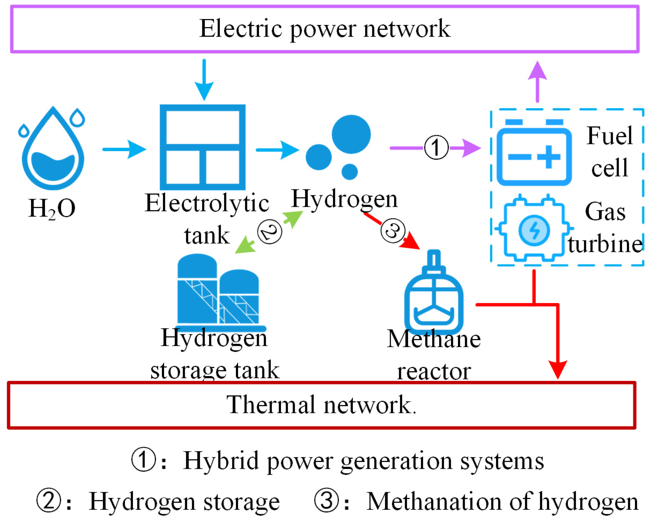
In summary, as illustrated in Figure 1, the multimodal utilization routes of hydrogen can significantly enhance the hydrogen utilization efficiency, markedly improving the overall energy utilization rate of the system.
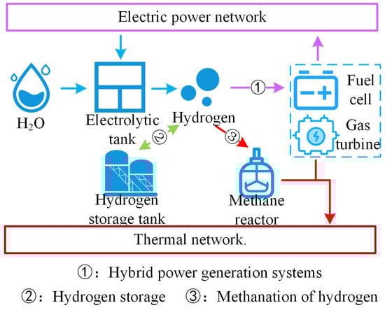
Figure 1.
Hydrogen energy multimodal utilization roadmap.
3. Structure of EHT-IES with Hydrogen Energy Systems and Advantages
3.1. Main Structure of EHT-IES with Hydrogen Energy Systems
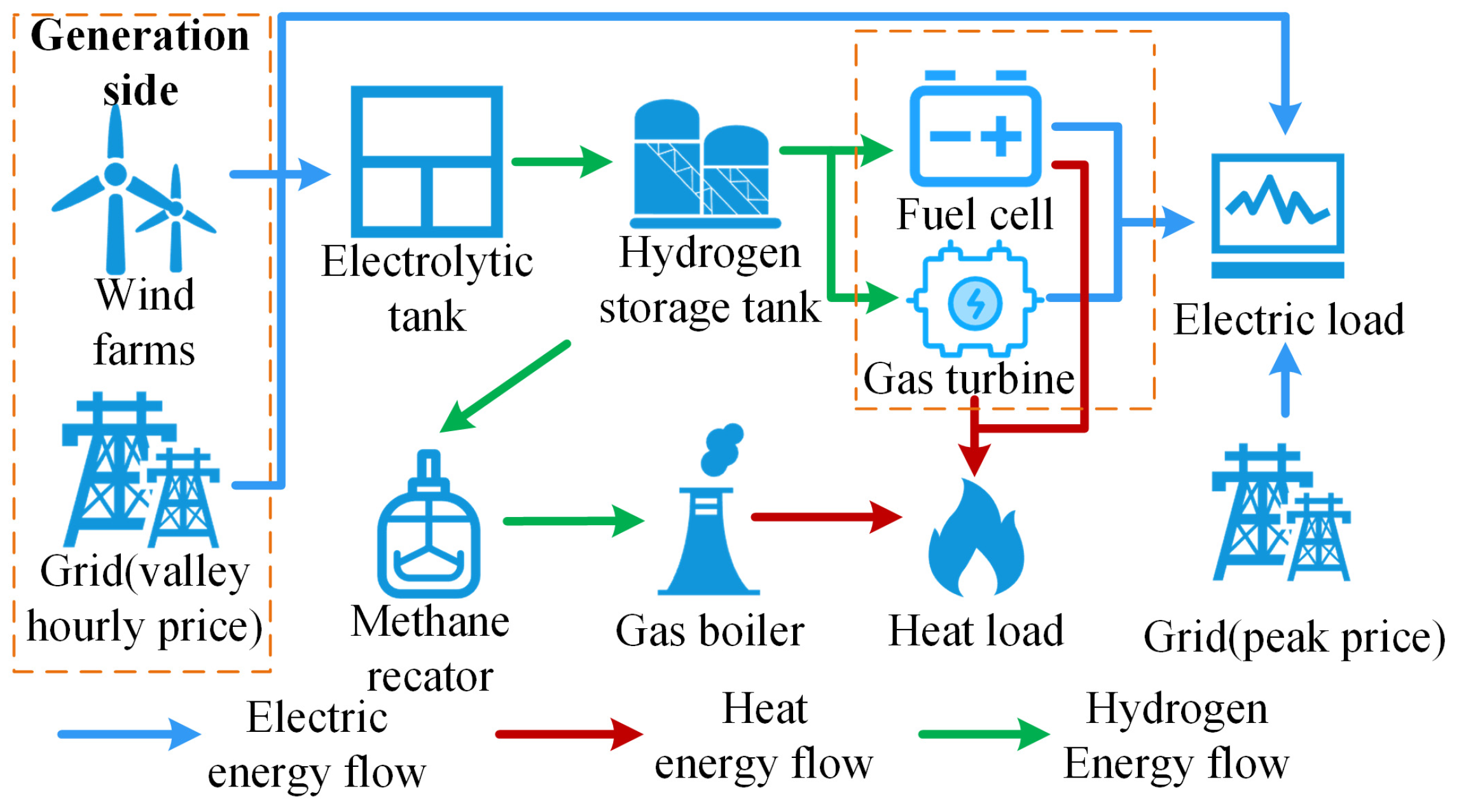
The main structure of the EHT-IES with hydrogen energy systems is shown in Figure 2. The EHT-IES can be divided into three parts: “Electricity”, “Hydrogen”, and “Thermal”.
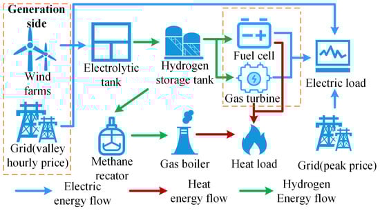
Figure 2.
Structures of EHT-IES with hydrogen energy systems.
The “Electricity” part encompasses various power supply methods, including the main power grid, wind power, and a fuel cell and gas turbine hybrid power generation system. Specifically, when wind power output is insufficient to meet the total electricity demand, the main power grid plays a safeguarding role. This design not only ensures the continuity and reliability of power supply but also helps to reduce wind curtailment through grid dispatch when there is an excess of wind power. Furthermore, when wind power generation is unstable or insufficient, the hybrid power generation system can utilize the hydrogen produced within the system to provide the necessary power, thereby improving the system’s energy efficiency and overall sustainability.
The “Hydrogen” part includes electrolyzers, hydrogen storage tanks, the fuel cell and gas turbine hybrid power generation system, and a methane reactor. It covers multiple key aspects of hydrogen production, storage, utilization, and conversion.
The “Thermal” part involves a range of equipment and systems related to thermal energy production and utilization, including the main natural gas network, methane reactor, gas boiler, and the fuel cell and gas turbine hybrid power generation system. The main task of the “Thermal” part is to meet the thermal load demand of the EHT-IES through the coordinated operation of various heat supply devices. Specifically, the hybrid power generation system provides thermal energy through cogeneration while generating electricity. The main natural gas network and methane reactor supply gas to the gas boiler, which burns the natural gas to provide the required thermal energy. The use of the gas boiler offers a flexible and reliable thermal energy supplement, ensuring that the continuous demand for thermal energy from users is met.
3.2. Advantages
Compared with traditional energy systems, EHT-IESs with hydrogen energy systems have the following four distinct technological advantages:
- (1)
- Enhanced renewable energy integration: Hydrogen energy systems significantly improve the capability of the EHT-IES to integrate and manage new renewable energy sources. They can store and release energy over longer periods and in larger amounts than traditional battery storage, making them ideal for storing excess energy from intermittent sources like solar and wind.
- (2)
- Economic efficiency with scale: The economic efficiency of hydrogen energy storage improves with scale and duration. As storage scale increases, the total cost decreases due to economies of scale in production and operational efficiencies, making hydrogen storage increasingly viable for large-scale energy storage applications.
- (3)
- Flexibility in storage and transportation: Hydrogen energy offers exceptional flexibility in storage and transportation. Hydrogen can be easily transported over long distances via pipelines or high-pressure tanks, enabling its use in a variety of settings without heavy infrastructure investments.
- (4)
- Geographical adaptability and ecological protection: Hydrogen storage technologies are geographically adaptable and environmentally benign. Unlike other energy storage methods that may have specific geographical requirements, hydrogen storage does not impose such limitations. Additionally, hydrogen energy systems produce only water as emission, making them environmentally preferable and compliant with strict regulations.
Overall, the anticipated decrease in the cost of electrolyzers due to technological advancements is expected to further increase the adoption of hydrogen energy systems, displacing more environmentally invasive and geographically constrained battery storage solutions in the long term.
4. EHT-IES Scheduling Formulation and Solution
This paper concentrates on the external characteristics of the EHT-IES and the overarching energy scheduling challenges. While the internal nonlinear dynamics of components such as electrolyzers, fuel cells, and gas turbines are significant on short time scales, these effects can be approximated by linear models over the extended time scales under consideration (e.g., hours or days). This simplification enables a more manageable analysis of the system’s performance and scheduling efficiency over longer periods [35].
4.1. Hydrogen Energy Systems
4.1.1. Electrolyzer Model
The use of surplus wind energy or low-cost electric power for the electrolysis of water to produce hydrogen and then the storage of hydrogen in storage tanks is considered. Given that the peak power of the electrolytic cell required for this study is 1000 kW, a flexible and efficient electrolyzer type is necessary. PEMECs are ideal due to their ability to handle variable loads and rapid response times, making them suitable for fluctuating power inputs typical in renewable energy integration. A PEMEC with a nominal capacity slightly above the peak power requirement is recommended to handle the highest loads effectively. For example, a model like the Siemens Silyzer 300, manufactured by Siemens Energy in Erlangen, Germany, or similar, typically available in scalable units up to several megawatts (MW), offers around 65–70% efficiency and can operate efficiently under partial loads [36]. This selection ensures that the electrolyzer can handle the power requirements efficiently and flexibly, making it the optimal choice for the scenario studied in this paper.
For an electrolyzer with an input electric power during period t, its model can be expressed as follows:
where represents the operating cost of the electrolyzer during period t, in CNY per hour; is the operating cost coefficient of the electrolyzer, in CNY per kWh; is the hydrogen production during period t, in cubic meters per hour under normal conditions; ε is the electricity-to-hydrogen conversion coefficient, in cubic meters per kWh; and ηEH is the efficiency of the electrolyzer.
4.1.2. Hydrogen Storage Tank Model
This paper focuses on the use of high-pressure composite hydrogen storage tanks to provide stable hydrogen energy for a hybrid power generation system. The primary objective of this study is to explore various utilization modes of hydrogen energy. By considering the hydrogen production and storage processes as a unified system, we aim to compare the effects of different hydrogen utilization scenarios on the EHT-IES. In all comparative scenarios, the hydrogen production and storage processes remain consistent. Given that the cost of compressing hydrogen is related to the storage volume, this study does not account for compression costs. The model for the hydrogen storage tank is established as follows:
where and represent the amounts of hydrogen stored in the storage tank during periods t and t − 1, respectively, in cubic meters per hour (Nm3/h). and refer to the inflow and outflow rates of hydrogen to and from the storage tank during period t, respectively, in cubic meters per hour (Nm3/h). ηHS denotes the efficiency of hydrogen storage in the tank.
4.1.3. Fuel Cell Model
Compared to PEMFCs, which require liquid electrolytes, SOFCs use solid electrolytes that do not leak, making them easier to maintain. Additionally, SOFCs can directly convert the chemical energy of carbon monoxide (CO) into electrical energy through their unique high-temperature electrochemical processes, whereas PEMFCs are susceptible to CO poisoning. A distinctive feature of SOFCs compared to traditional fuel cell technologies is their operation mechanism based on high temperatures. This high-temperature mechanism endows SOFCs with significant fuel flexibility advantages. These fuel cells use oxygen ions as charge carriers and can operate efficiently at around 1000 °C. The high-temperature conditions not only allow SOFCs to use a variety of fuels, including but not limited to pure hydrogen, natural gas, and other carbon-based fuels, but also make them particularly valuable in CHP systems. Specifically, the high-temperature heat released by SOFCs can be effectively utilized to supply heat loads, achieving efficient energy use. Furthermore, the operating temperature range of SOFCs matches that of gas turbines, making them ideal complementary devices that can work synergistically with gas turbines in hybrid power systems, thereby enhancing overall system stability and energy conversion efficiency. Therefore, this paper selects SOFCs as the type of fuel cell [37]:
where represents the operating cost of the hydrogen fuel cell during period t, in CNY per hour; is the operating cost coefficient, in CNY per kWh; denotes the voltage of a single hydrogen fuel cell, in kV; is the Nernst potential, in kV; is the activation voltage, in kV; refers to the ohmic voltage, in kV; is the concentration voltage, in kV; indicates the number of hydrogen fuel cells; is the current flowing through a single cell, in amperes; represents the hydrogen power consumed by the fuel cell, in kW; are the electrical power and thermal power outputs from the hydrogen fuel cell, respectively, in kW; and are the electrical and thermal efficiencies of the hydrogen fuel cell, respectively.
4.1.4. Gas Turbine Model
This paper selects the Siemens SGT-400 gas turbine, which is recognized for its high fuel flexibility and reliability. It can adapt to various fuel types, including natural gas, liquefied petroleum gas (LPG), liquefied natural gas (LNG), and hydrogen, with the capability to use up to 100% of hydrogen fuel. This flexibility and adjustability ensure that the SGT-400 gas turbine can be effectively utilized across a variety of application scenarios, providing crucial support for the development of the hydrogen energy industry. The mathematical model is as follows [38]:
where represents the operating cost of the hydrogen-fueled gas turbine during period t, in CNY per hour; is the operating cost coefficient for the hydrogen-fueled gas turbine, in CNY per kWh; represents the hydrogen power consumed by the gas turbine, in kW; and denote the electrical power output and thermal power output of the hydrogen-fueled gas turbine during period t, respectively, in kW; is the electrical efficiency of the hydrogen-fueled gas turbine; and represents the heat-to-power ratio of the hydrogen-fueled gas turbine.
4.1.5. Methane Reactor Model
Hydrogen is introduced into a methane reactor where it reacts with carbon dioxide to produce natural gas and water. The mathematical model is as follows:
where represents the natural gas power output of the methane reactor at time t; is the hydrogen power input to the methane reactor at time t; is the energy conversion efficiency of the methane reactor.
4.1.6. Gas Boiler Model
A gas boiler converts chemical energy from burning natural gas into thermal energy, which is then supplied to heat users. Due to the high stability of gas boilers and a gas-to-heat conversion efficiency of up to 93%, the thermal efficiency can be considered approximately constant. Therefore, there is a linear relationship between the thermal power output and the input gas power of the gas boiler. The mathematical model for this process is as follows:
where represents the operating cost of the gas boiler during period t, in CNY per hour; is the unit operating cost coefficient for the gas turbine, in CNY per kWh; denotes the thermal power output of the gas boiler during period t, in kW; is the gas power consumed by the gas boiler during period t, also in kW; represents the gas-to-heat efficiency of the gas boiler, reflecting its heating performance.
4.2. Objective Function
The system aims to maximize the utilization of the coupling characteristics between electrical energy, hydrogen energy, and thermal energy to optimize system operation and improve energy efficiency. By fully leveraging the interrelationships between different energy sources, efficient energy conversion and storage can be achieved, offering new possibilities for comprehensive energy transformation.
This paper establishes an optimized dispatch model for multimodal hydrogen energy utilization with the goals of minimizing the electrothermal operating costs of the system and maximizing the integration of wind energy. The objective function is as follows:
where represents the operating cost of the system; represents the cost of wind curtailment.
where represent the cost per unit time for purchasing electricity, for operating the electrolyzer, for running the hydrogen-fueled gas turbine, for operating the hydrogen fuel cell, for the curtailed wind energy, and for the gas boiler, respectively, in CNY; is the simulation time step, and T is the total number of time intervals in a dispatch period; is the power purchased by the system from the upper-level power grid during period t; represents the electricity price during the time period t represents the cost of wind curtailment per unit time; represents the penalty coefficient for wind curtailment, in CNY per kWh; denotes the wind power curtailed during period t, in kW; represents the actual power generated from wind during period t; and is the predicted power of wind energy during time period t.
4.3. Constraint Conditions
4.3.1. Power Supply Balance
4.3.2. Heat Supply Balance
4.3.3. Gas Power Balance
4.3.4. Hydrogen Power Balance
4.3.5. Wind Power Output Constraint
4.3.6. Electrolyzer Power Constraints
4.3.7. Power Constraints of the Hydrogen Storage Tank
4.3.8. Unit Output Constraints
The proposed scheduling model for the electricity–hydrogen–heat coupled system is a mixed-integer linear programming (MILP) model, which can utilize established commercial solvers such as Gurobi and Cplex to solve scheduling strategies.
5. Case Studies and Results
5.1. Case Settings
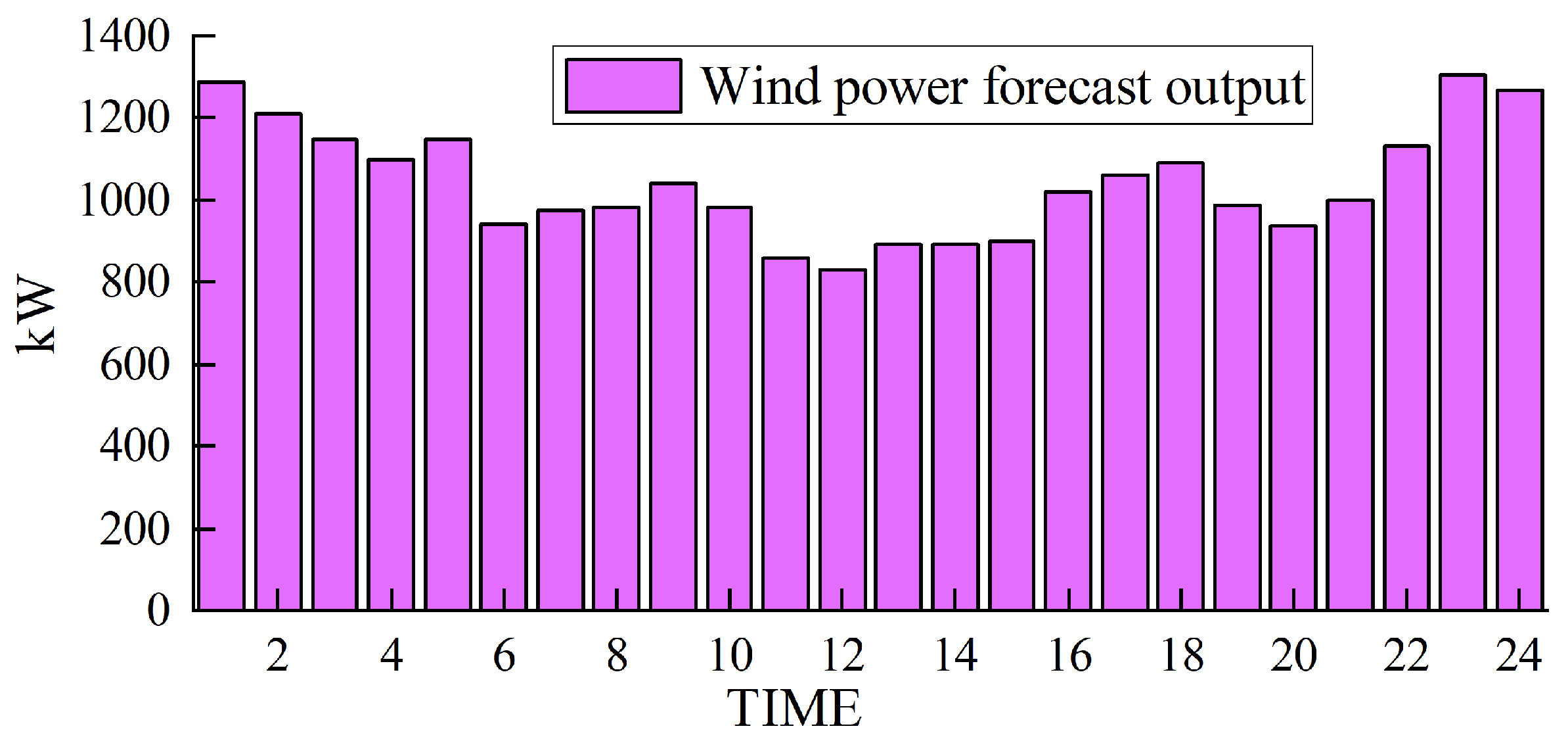
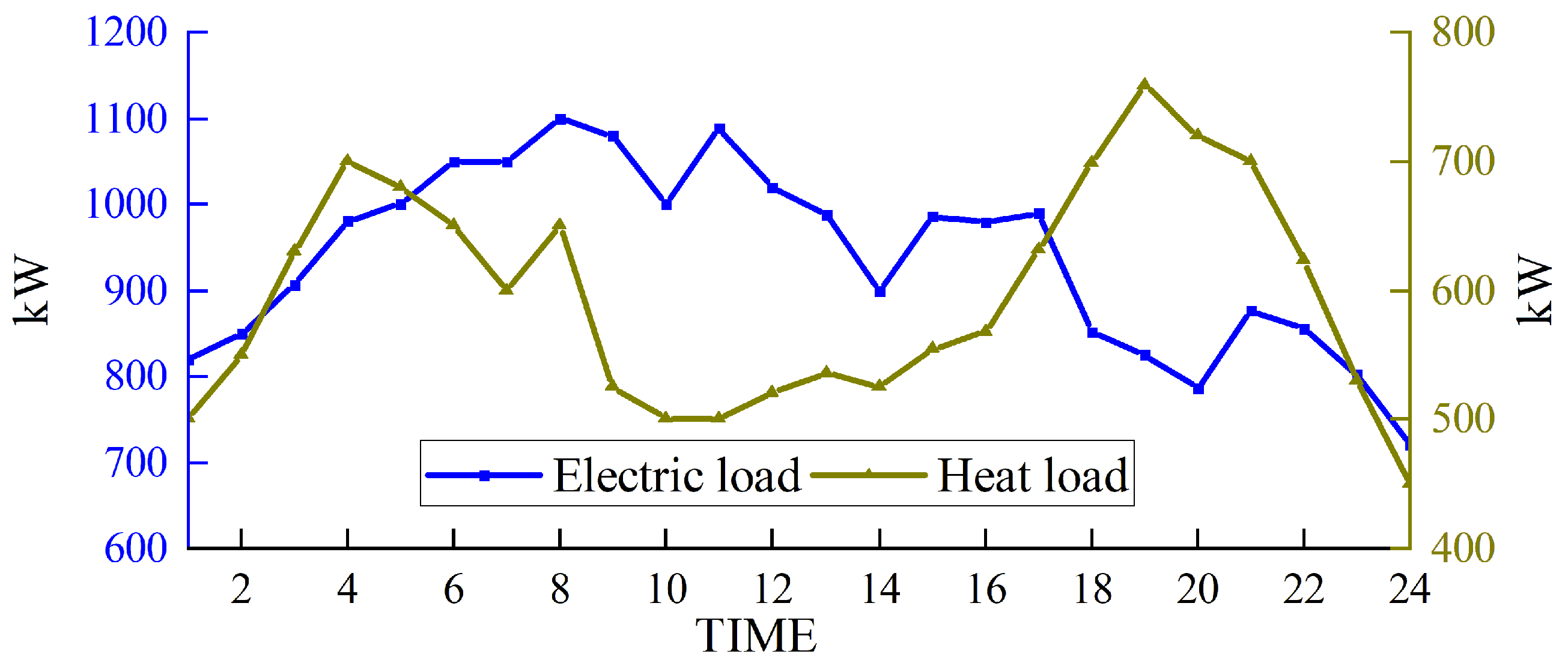
Based on solving the day-ahead scheduling problem, this study takes 1 h as the simulation time step, the lowest daily operating cost as the goal, and the winter in Northwest China [39], where wind abandonment is more serious, as the scenario for the example simulation. The data were sourced from actual wind power plants in the northwestern region of China, and the ARIMA (autoregressive integrated moving average) prediction method was employed to forecast a characteristic day, which serves as the load data utilized in this study. For a visual representation of our data, please refer to Figure 3 for the predicted renewable energy output and Figure 4 for the forecasted conventional load. We developed a 24 h optimal scheduling plan for each device of the electric–hydrogen–thermal coupled system.
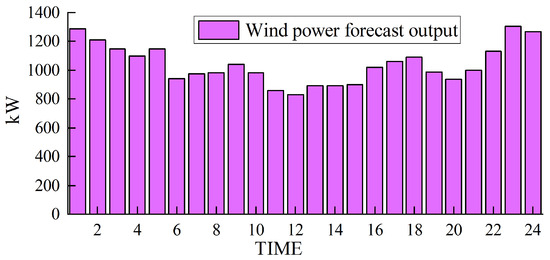
Figure 3.
Forecasted wind power output.
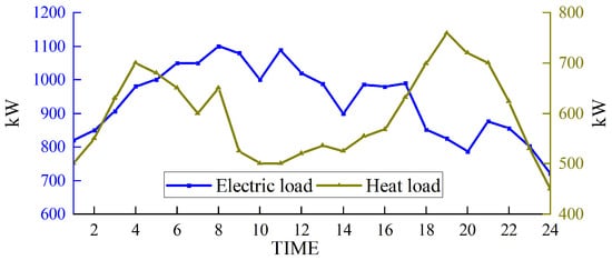
Figure 4.
Forecasted conventional load.
This paper selects electrolytic cells, hydrogen storage tanks, fuel cells, gas turbines, and gas boilers as the main devices. This study aims to investigate the overall operational characteristics and energy scheduling strategies of the EHT-IES. To streamline the model and mitigate computational complexity, a fixed-size assumption is employed throughout the analysis. The parameters for the electrolytic cell are set as follows: ε = 0.19 Nm3/kWh, = 70%. The parameters for the hydrogen storage tank are set as follows: the capacity of the storage tank is 1000 m3, = 95% [40], and the initial hydrogen stored in the tank is half of the rated capacity, which is 500 m3. The parameters for the hydrogen fuel cell are set as follows: = 70%, = 45%. The parameters for the hydrogen gas turbine are set as follows: = 40%, = 1.5, and the proportion of hydrogen in the fuel is set to 100%. The parameters for the gas boiler are set as follows: = 93%; wind curtailment penalty factor = 0.32 CNY/kWh.
In this paper, we selected several key devices for our study, including electrolytic tanks, hydrogen storage tanks, fuel cells, hydrogen gas turbines, and gas boilers. Our analysis is based on a time-based pricing structure for electricity, which is outlined as follows:
The peak periods occur from 9:00 a.m. to 12:00 p.m. and from 5:00 p.m. to 8:00 p.m., with a tariff rate of 1.20 CNY per kilowatt-hour (kWh). The off-peak period runs from 11:00 p.m. to 6:00 a.m. the following day, featuring a reduced tariff of 0.38 CNY per kWh. All other hours fall within the normal pricing period, with a tariff rate of 0.68 CNY per kWh.
This paper develops an optimization scheduling model for the EHT-IES as an MILP model, which can be solved using mature commercial solvers such as Gurobi and Cplex.
5.2. Simulation Results
The simulation results obtained with the method proposed in this paper are presented in Figure 5, Figure 6, Figure 7 and Figure 8.

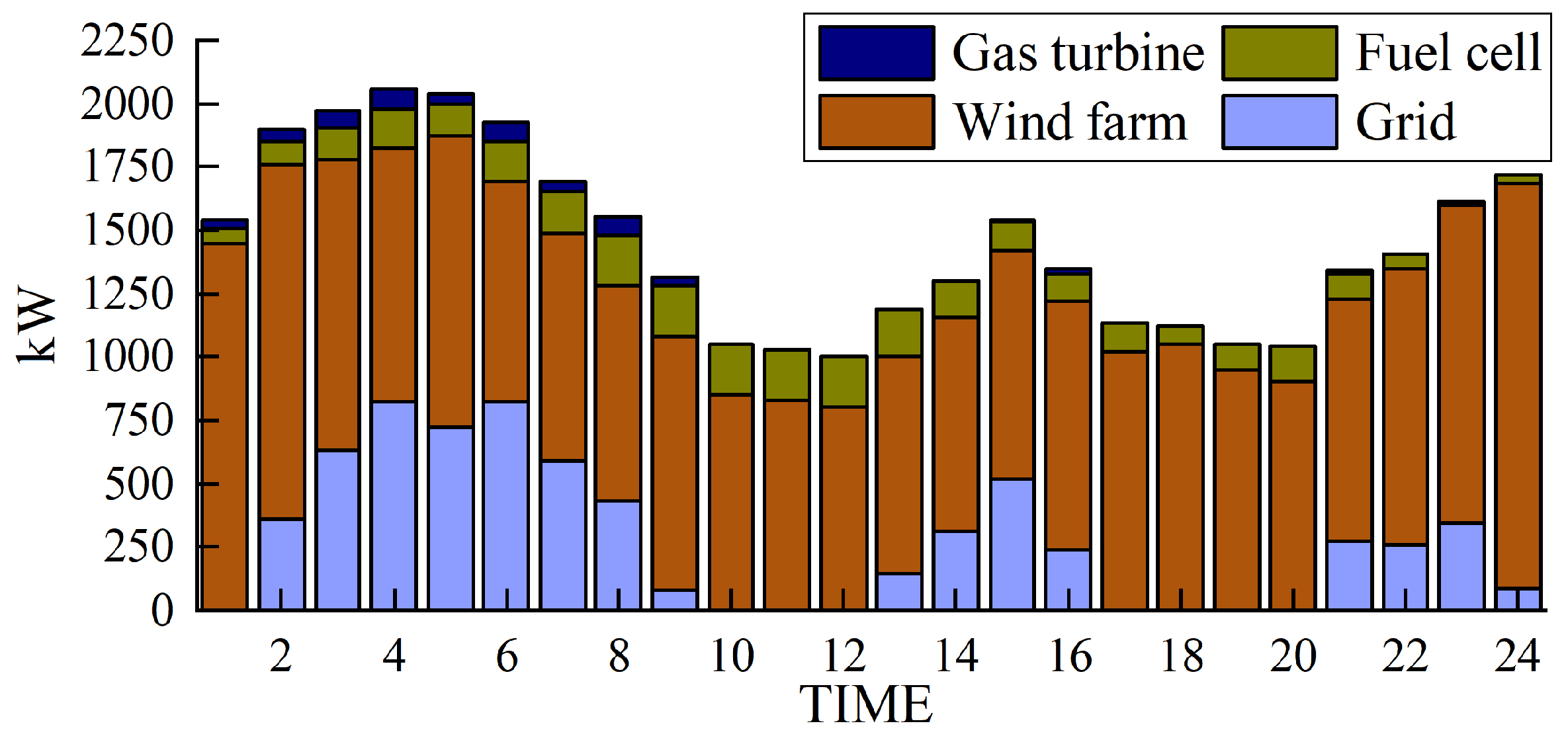
Figure 5.
Electrical power output.
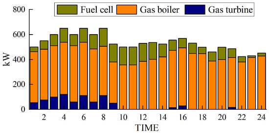
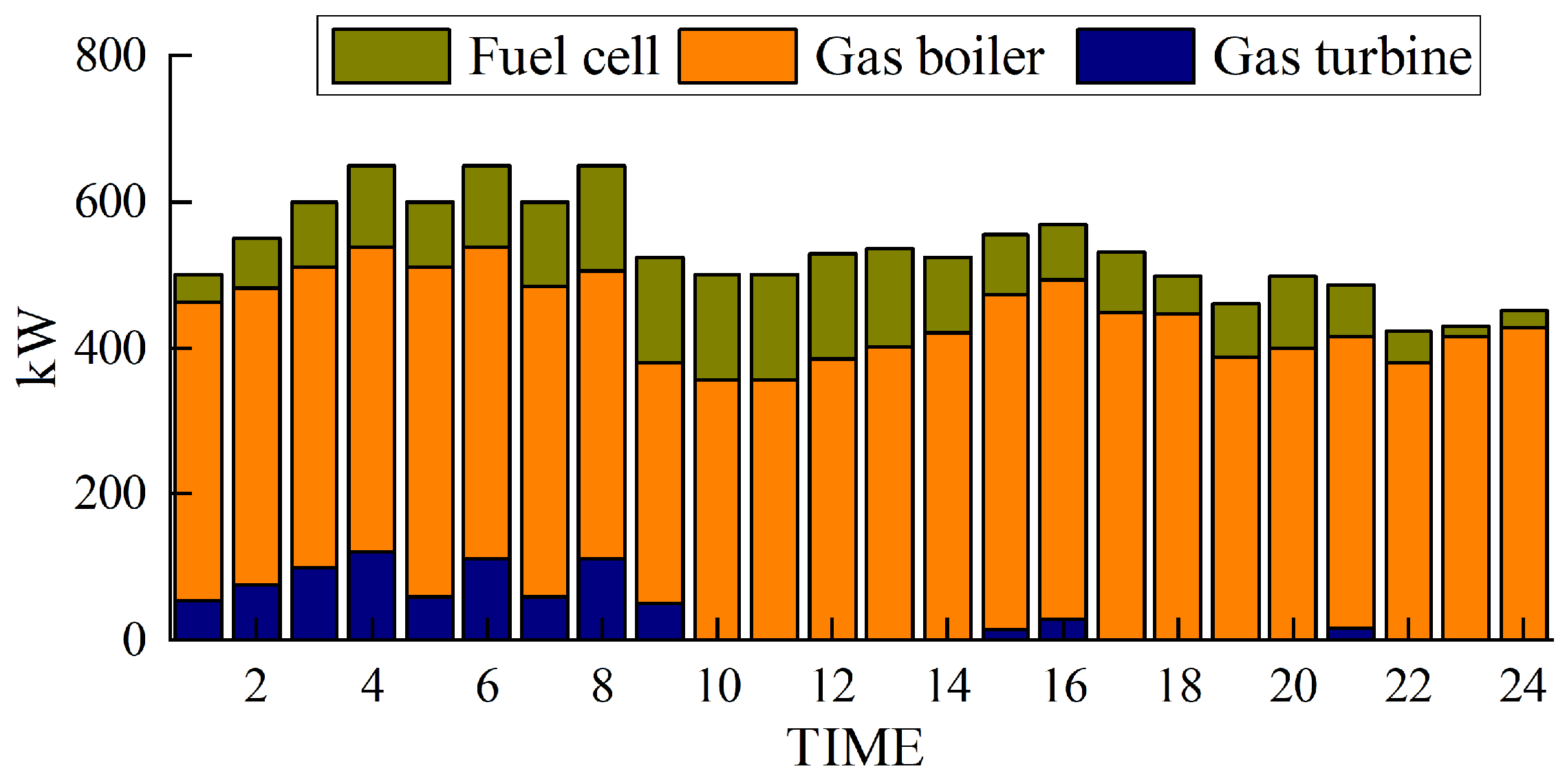
Figure 6.
Thermal power output.
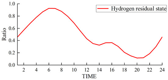
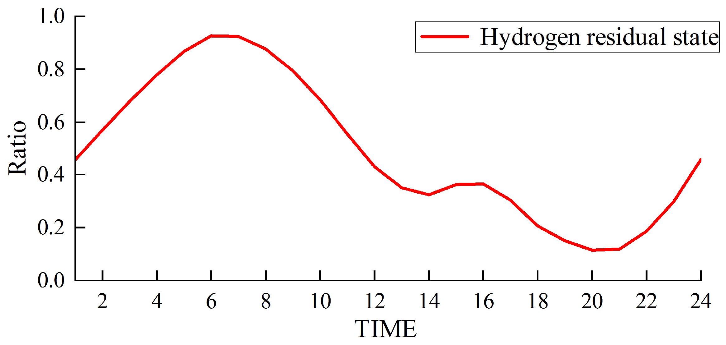
Figure 7.
Hydrogen storage status of the hydrogen storage tank.
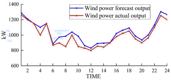
Figure 8.
Wind power output.
Using Figure 5 as an example, the model is solved using the Cplex solver to determine the hourly power output values of the gas turbine, fuel cell, wind power, and grid purchases. By stacking these values, a 24 h output profile of the power generation equipment can be obtained.
Figure 5 and Figure 6 depict the output of the hydrogen storage unit, while Figure 7 illustrates the variations in the hydrogen storage tank. Additionally, Figure 8 provides insight into the wind power consumption. The overall operating cost of the system employing this method is 418,853 CNY.
Table 4.
Hydrogen storage and energy management schedule.
Furthermore, our approach prioritizes wind power when catering to the load requirements in each designated period. If there is excess wind power generation, then this surplus energy is channeled toward the electrolysis of water for hydrogen production and subsequent storage. Conversely, when wind power production decreases, a hydrogen storage tank is employed to satisfy the remaining load demand.
Figure 5 and Figure 6 provide notable insights. They reveal that electrolytic tanks, hydrogen storage tanks, gas boilers, and fuel cells are active in nearly all periods. Gas boilers judiciously operate to meet thermal load demands, achieving an impressive comprehensive utilization efficiency exceeding 90%. Notably, the surplus hydrogen within the hydrogen storage tank follows the pattern of hydrogen production during low-electricity-price periods and hydrogen usage during high-electricity-price periods.
Furthermore, Figure 8 illustrates that our approach ensures a minimal wind abandonment rate of only 3.91%. This low rate is indicative of substantial improvements in the energy utilization efficiency following the integration of hydrogen storage technology. By effectively utilizing hydrogen storage, the strategy optimizes the usage of wind-generated energy, minimizing unnecessary waste and concurrently curtailing the financial drawbacks typically associated with unused wind energy. This strategic incorporation of hydrogen storage not only elevates the overall energy use efficiency but also plays a critical role in enhancing the economic viability and environmental sustainability of the energy system.
5.3. Flexibility Enhancement Analysis
5.3.1. Comparative Experiment
The multi-mode utilization of hydrogen energy can enhance energy efficiency and reduce the operational costs of the EHT-IES. In contrast, dual-mode and single-mode utilization of hydrogen energy fail to fully exploit its potential, leading to higher instances of wind curtailment and increased economic costs. To highlight the advantages of multi-mode utilization of hydrogen energy, the following comparative case is established and compared with the simulation results obtained in this study.
- (1)
- Hydrogen dual-mode utilization
The hydrogen injection into the methane reactor for methane production, which is considered in the hydrogen multi-mode, is canceled. At this time, the hydrogen energy utilization mode includes hydrogen storage and hydrogen injection into the mixed power generation system for combined heat and power generation. Natural gas required by the system is purchased directly from the gas network. The simulation result shows that the total operating cost of the system is 493,515 CNY.
- (2)
- Hydrogen single-mode utilization
The combined heat and power generation in the hydrogen dual-mode utilization is canceled. At this time, the hydrogen energy utilization mode is only the hydrogen storage mixed system power generation, and the heat load is fully satisfied by the gas boiler. Natural gas required by the system is purchased directly from the gas network. The simulation result shows that the total operating cost of the system is 611,094 CNY.
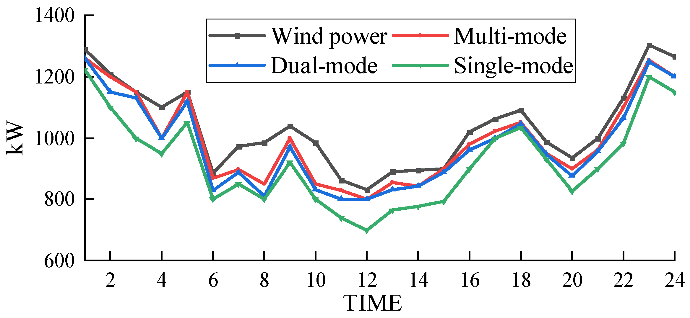
The wind power absorption of the electric–hydrogen–thermal coupled system under different hydrogen energy utilization modes is shown in Figure 9.
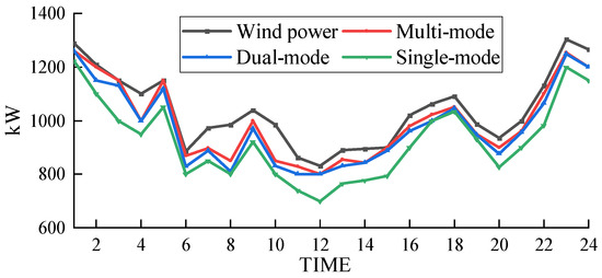
Figure 9.
Wind power consumption under different utilization modes.
- (3)
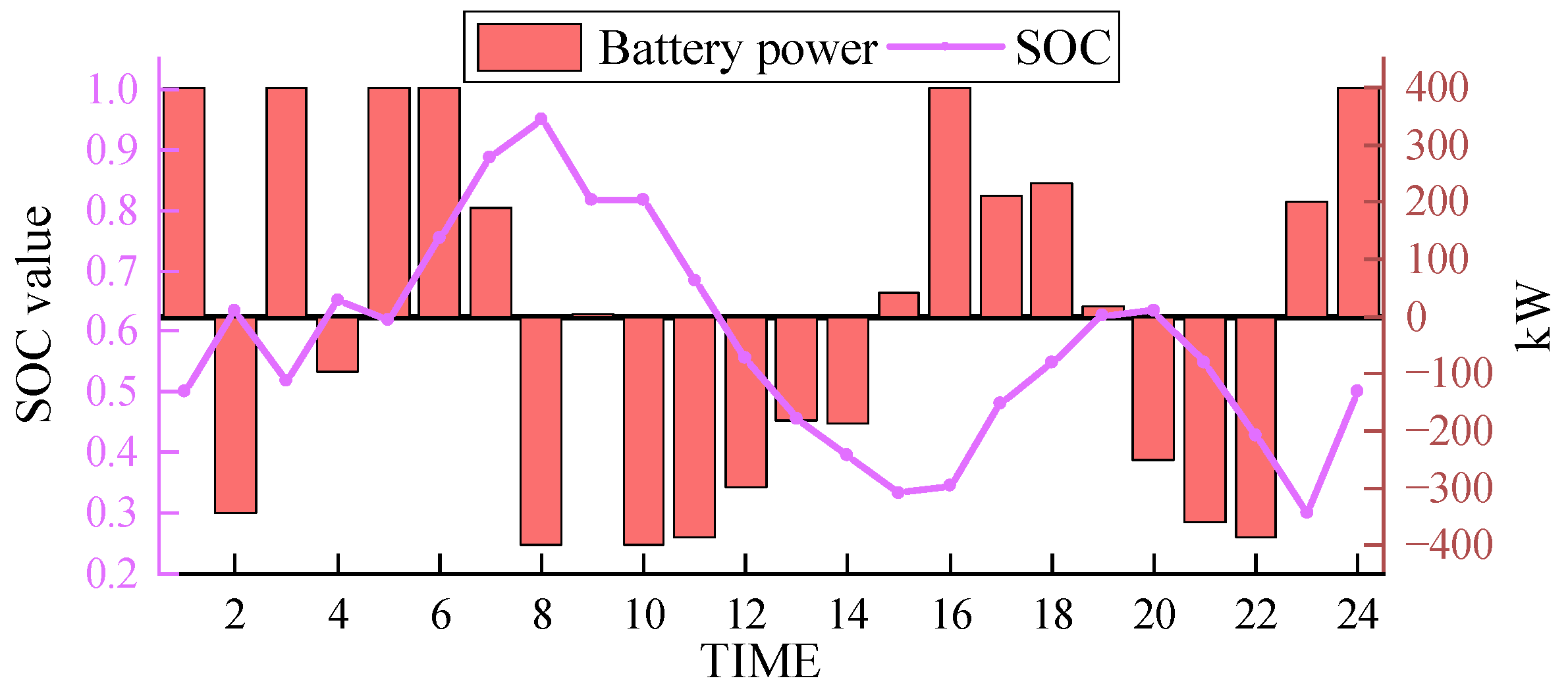
- Electrochemical Energy Storage Replacement
Lithium-ion batteries with high power rating and large energy density are selected to replace the hydrogen storage tank in the hydrogen multi-mode utilization scheme, forming a comparative case of electrochemical energy storage. Five sets of lithium battery packs with a capacity of 100 kW are combined to form the electrochemical energy storage unit for the comparative case in this paper, and the state of charge of the lithium batteries is set between 0.1 and 0.9.
In the same scenario, the results obtained from simulation using the electrochemical energy storage scheme are shown in Figure 10 and Figure 11. SOC (state of charge) represents the current level of charge in the energy storage system.
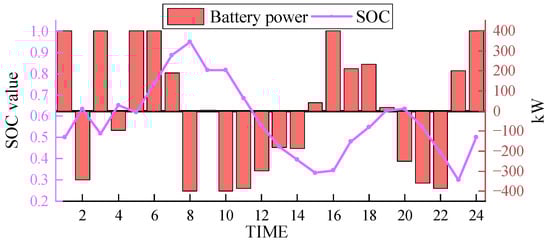
Figure 10.
Electrochemical energy storage output.
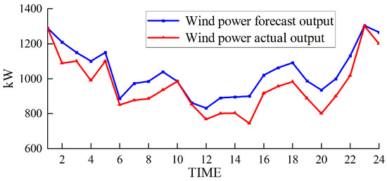
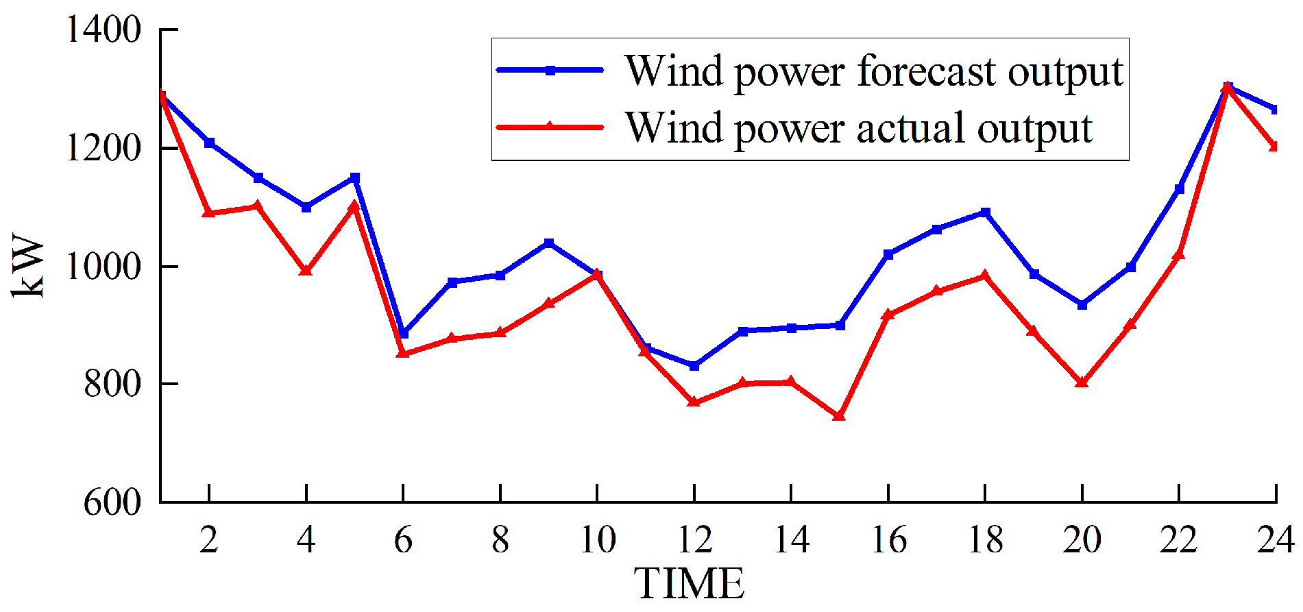
Figure 11.
Wind power output under the electrochemical energy storage scheme.
5.3.2. Analysis and Discussion
Based on Figure 9 and Figure 11, it can be observed that the curtailment rates of wind power under hydrogen single-mode utilization and dual-mode utilization are 5.22% and 4.16%, respectively, while the curtailment rate under the electrochemical energy storage scheme is 7.66%. These rates are all higher than the curtailment rate of the proposed scheme in this paper (3.91%). This is because under hydrogen single-mode utilization and dual-mode utilization, the system relies only on externally supplied natural gas, which means that the hydrogen gas needed to produce natural gas within the coupled system cannot be utilized in a timely manner. This leads to an accumulation of hydrogen gas in the hydrogen storage tank, preventing the coupled system from effectively absorbing more wind power and causing the curtailment rate to increase. On the other hand, the energy storage capacity of lithium battery packs is limited, and their ability to respond to wind power fluctuations is relatively weak. When wind power generation exceeds the load demand, the capacity of the lithium battery packs may quickly reach saturation, preventing them from storing additional electricity and resulting in curtailment of wind power.
In contrast, the hydrogen multi-mode utilization scheme proposed in this paper has a larger hydrogen storage capacity and a longer energy storage cycle. It can absorb more wind energy, and the hydrogen storage tank can flexibly store hydrogen gas without being limited by critical capacity. Therefore, it performs better in wind energy absorption and has a lower curtailment rate.
The output of the electrochemical energy storage solution, as depicted in Figure 10 (positive values indicate charging, and negative values indicate discharging), reveals that the lithium-ion battery packs exhibit a substantial output. The average output is close to 300 kW, reaching approximately 400 kW in multiple periods, representing approximately 80% of the full load capacity. The lithium-ion battery packs undergo frequent charge and discharge cycles within the dispatch period, adhering to a typical pattern. However, due to rigid energy storage capacity constraints, the adjustment capability of lithium-ion battery packs is limited, thereby reducing the peak shaving ability and overall energy utilization efficiency.
In comparison, the hydrogen storage tank provides a flexible transitional period for charging and discharging in the EHT-IES, effectively eliminating rigid energy storage capacity constraints and enhancing the overall capacity. This implies that in terms of scheduling and addressing energy demand fluctuations, the EHT-IES exhibits greater flexibility and adaptability than the electrochemical energy storage solution. By leveraging the hydrogen storage capacity of the storage tank, the EHT-IES is better equipped to address energy supply and demand variations during peak and off-peak periods, ultimately reducing energy wastage.
5.4. Economic Advantages
5.4.1. Cost Comparison Analysis of Different Hydrogen Utilization Modes
As shown in Table 5, when the utilization modes of hydrogen decrease, the efficiency of hydrogen utilization decreases accordingly, leading to a sharp increase in the system’s operating costs. This is because under the hydrogen single-mode and dual-mode utilization, the system needs to purchase natural gas from the outside, resulting in continuously rising operating costs. However, in the hydrogen multi-mode utilization proposed in this chapter, the system can produce natural gas through the methane reactor, obtaining it at a much lower cost than purchasing it directly from the outside. Additionally, if there is surplus hydrogen energy after the electrical and thermal loads of the system are fully met, the hydrogen can be converted into natural gas and sold to the gas network, further reducing the operating costs of the system.
Table 5.
Cost comparison of different hydrogen energy utilization modes.
Therefore, by adopting the hydrogen multi-mode utilization scheme, the system can utilize the hydrogen energy it produces and convert it into more economically viable natural gas, thereby reducing operating costs. This multi-mode utilization strategy not only improves the efficiency of energy utilization but also reduces reliance on external energy sources, further promoting the goal of sustainable development.
5.4.2. Cost Comparison Analysis of Different Energy Storage Solutions
Table 6 provides a comparison of wind power absorption and costs between hydrogen storage and electrochemical storage. The “Consumption/kW” values are derived from the scheduling results presented in Figure 8 and Figure 11. Specifically, the “Consumption/kW” values are obtained by summing the wind power consumption for each time period shown in Figure 8 and Figure 11. Overall, electrochemical energy storage demonstrates high economic viability. This can be attributed to the maturity of electrochemical energy storage technology and market-driven competition leading to a gradual reduction in costs. However, despite its economic advantages, electrochemical energy storage lags behind hydrogen storage in terms of accommodating new energy sources.
Table 6.
Cost comparison between hydrogen energy storage and electrochemical energy storage.
Hydrogen storage excels in integrating wind energy through the use of storage tanks, significantly reducing the wind abandonment rate. Hydrogen energy storage systems can store excess renewable energy generated during periods of low demand and release it during peak demand, providing a flexible and efficient way to balance supply and demand. This capability is particularly advantageous in regions with high renewable energy penetration and curtailment issues, such as northwest China during the heating season.
However, implementing hydrogen storage comes with certain economic costs. Compared to electrochemical energy storage, hydrogen storage involves additional technological and equipment investments, such as those for hydrogen production, storage, and utilization, which may increase the overall investment and operational expenses. The initial costs for hydrogen storage infrastructure can be substantial, encompassing the production facilities for electrolysis, storage tanks, and fuel cells or turbines for electricity generation.
When selecting the appropriate energy storage method, factors such as the energy absorption capacity, sustainability, and environmental impact, not just economic considerations, need to be comprehensively evaluated. Safety is a critical aspect of any energy storage system. Hydrogen storage systems have advanced significantly in terms of safety, utilizing robust materials and technologies such as composite tanks and solid-state storage options like metal hydrides, which minimize risks of leakage and explosion. Comprehensive safety protocols and industry standards ensure that hydrogen storage can be safely implemented even for long-term use. While battery storage systems also have safety considerations, including the risk of thermal runaway and fires, both storage technologies require stringent safety measures to ensure their safe operation. While electrochemical energy storage systems, such as lithium-ion batteries, offer high efficiency and are well suited for short to medium-term storage, hydrogen storage is also applicable for short-term storage scenarios. Hydrogen storage provides a higher energy density and the ability to store energy without significant losses, making it an attractive choice for applications requiring energy storage. Despite its traditional association with long-term storage, hydrogen’s unique characteristics enable its effective use in short-term storage applications as well.
In conclusion, the choice between hydrogen storage and electrochemical energy storage should be based on a holistic assessment of various factors, including the specific application requirements, environmental impact, and long-term sustainability. Integrating hydrogen storage into an EHT-IES can enhance energy security, reduce renewable energy curtailment, and improve overall system flexibility and efficiency. As part of our study, we have demonstrated that hydrogen storage, despite its higher initial costs, offers significant technical and economic benefits when integrated into a comprehensive energy system designed to optimize energy use across different sectors and time frames.
5.5. Comparison of Different Seasons
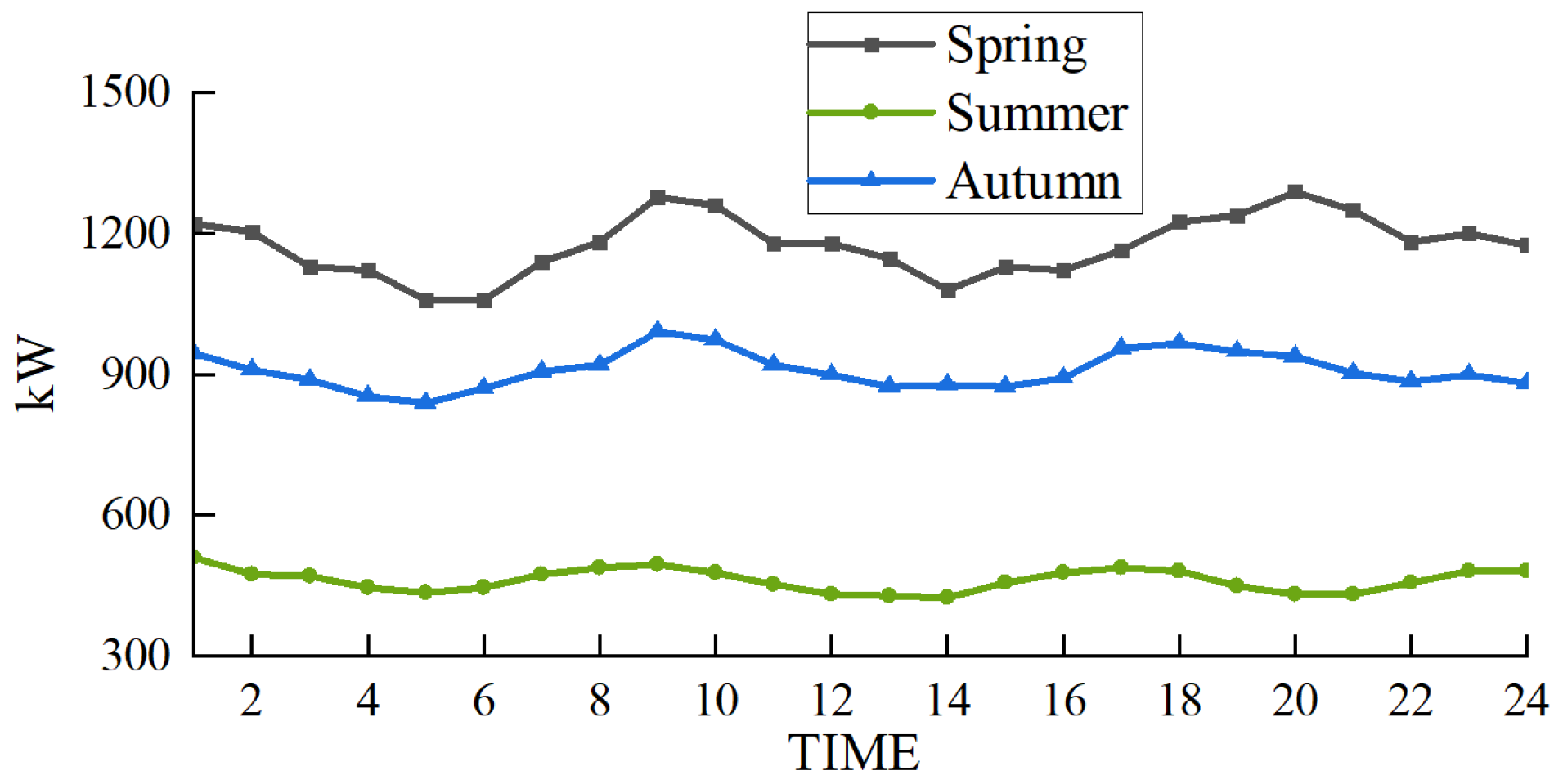
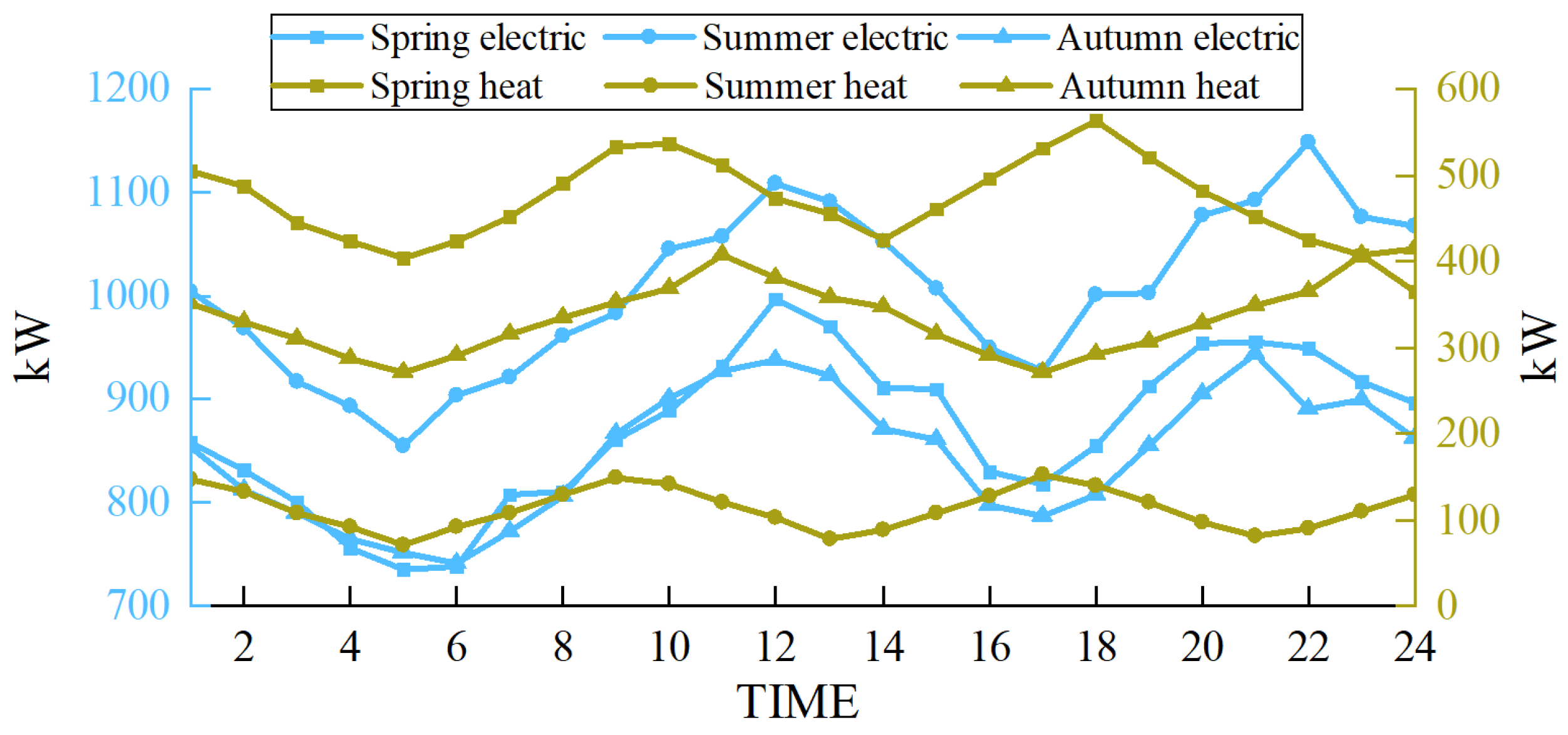
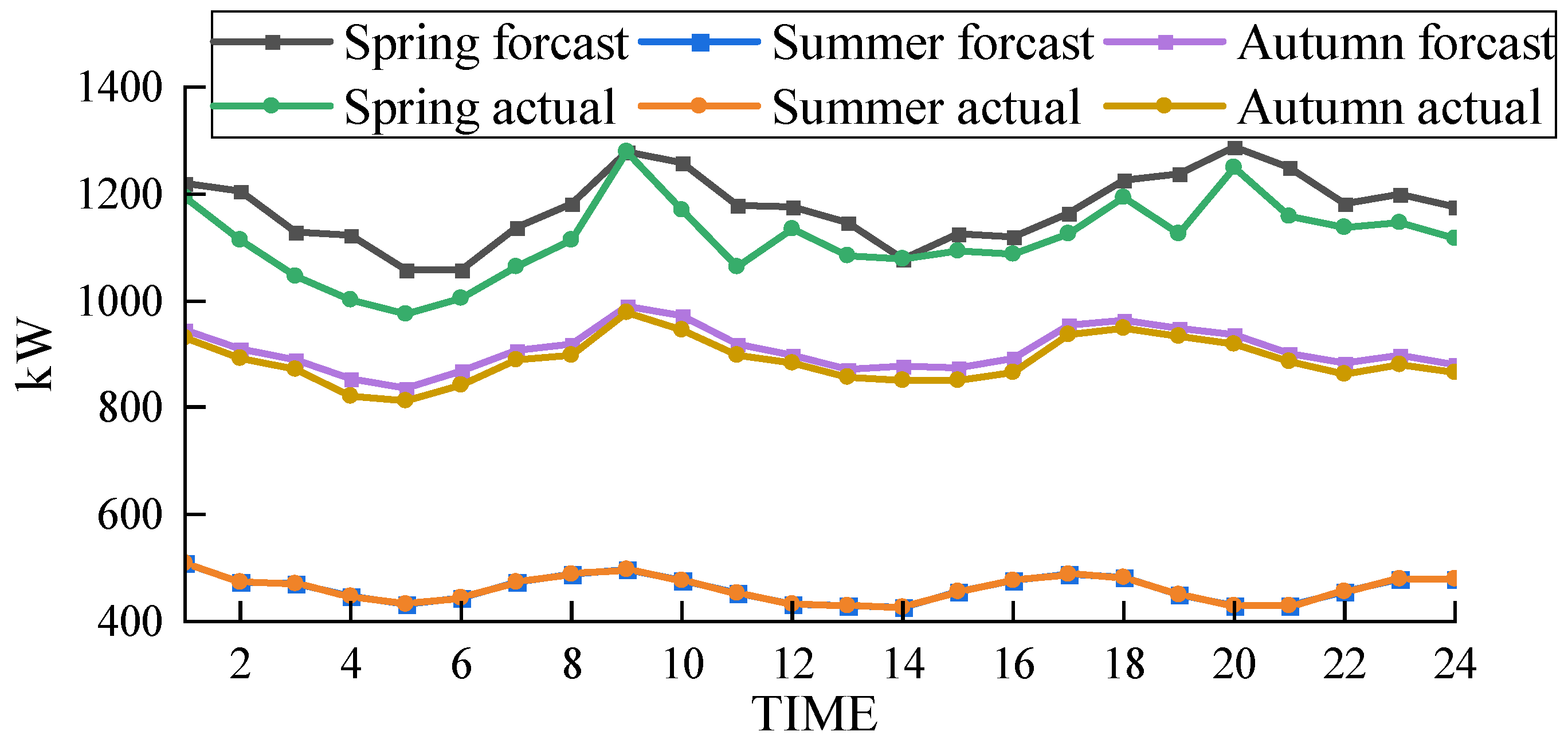
The scenarios selected in this paper are based on the heating season in the northwest region of China. To demonstrate the wide applicability of the proposed multimodal hydrogen utilization model, simulations were conducted for representative days in spring, summer, and autumn, following the methodology outlined in Reference [32]. The wind power forecast outputs and load curves for these three representative days are presented in Figure 12 and Figure 13, respectively.
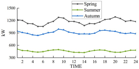
Figure 12.
Wind power output prediction in different seasons.
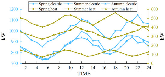
Figure 13.
Load in different seasons.
In the scheduling of the EHT-IES with multimodal hydrogen utilization, the wind curtailment situations for the three seasons—spring, summer, and autumn—are shown in Figure 14. The wind curtailment rates are 2.2% for spring, 0% for summer, and 1.7% for autumn. This demonstrates that the proposed model has a wide applicability and performs well in terms of wind curtailment rates across different scenarios.
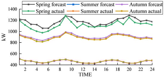
Figure 14.
Wind power consumption in different seasons.
The results indicate that the proposed EHT-IES model with multimodal hydrogen utilization is effective in minimizing wind curtailment throughout various seasons. The significant reduction in curtailment, especially the complete elimination in summer, highlights the model’s capacity to optimize energy use and enhance system flexibility. Consequently, the proposed model not only facilitates greater integration of renewable energy but also improves the overall efficiency and stability of the energy system. These findings suggest that the multimodal utilization approach can be a viable solution for regions with significant seasonal variations in energy demand and renewable energy supply.
6. Conclusions and Policy Suggestions
6.1. Conclusions
This paper proposes a multimodal hydrogen energy system and integrates it into the EHT-IES to address issues related to low hydrogen utilization efficiency. This study demonstrates that multimodal hydrogen utilization can effectively improve hydrogen energy efficiency, mitigate wind energy curtailment, and reduce the operational costs of EHT-IESs, thereby enhancing their overall flexibility.
By comparing different hydrogen utilization modes, it was found that the EHT-IES with multimodal hydrogen utilization has better wind power absorption capacity compared to single-mode and dual-mode hydrogen utilization. Additionally, when compared with different energy storage methods, hydrogen storage tanks provide a flexible transition space for charging and discharging, showcasing efficient energy conversion and superior peak-shaving capabilities. Furthermore, simulations conducted on characteristic days in spring, summer, autumn, and winter indicate that the multimodal hydrogen utilization scheme is suitable for all seasons and effectively absorbs wind energy.
6.2. Policy Suggestions
To promote the development of hydrogen energy and highlight the technological and economic dominance of the EHT-IES with hydrogen energy systems, we propose the following policy recommendations.
- (1)
- Implement subsidies or tax incentives to reduce the costs of electrolyzers and hydrogen fueling facilities. This strategy aims to make hydrogen energy storage competitive with other technologies while fostering environmental sustainability and economic growth. Engagement from government regulators, energy storage manufacturers, and renewable energy developers is crucial for the successful implementation of these incentives.
- (2)
- Enhance funding and support for research and development focused on improving the efficiency and operational longevity of electrolyzers. Optimizing operational protocols to minimize the frequency of startups and shutdowns can extend the service life of electrolyzer arrays and stabilize hydrogen production. This initiative will benefit from collaborations between academia, technology developers, and governmental agencies providing research grants.
- (3)
- Develop and deploy smart grid technologies that enable personalized load shifting recommendations based on real-time data analytics. These technologies should help distribute energy demand more evenly throughout the day, reducing peak loads and enhancing grid stability. Pilot projects by utility companies in high electric vehicle usage areas could demonstrate the effectiveness of these technologies before broader rollout.
- (4)
- Conduct detailed studies to determine the necessary expansion of electric vehicle (EV) charging infrastructure, focusing on the strategic placement and the number of new public chargers required to support the growing number of EVs. These studies should consider leveraging EV batteries as grid resources during peak demand times, enhancing grid flexibility and stability. Collaboration with urban planners, private sector investors, and transportation authorities will be essential.
6.3. Future Research Directions
- (1)
- Incorporate detailed cost calculations: Future research will focus on integrating specific power requirements and electricity costs associated with compressed hydrogen storage into our model. This includes examining the influence of various compressor technologies and hydrogen storage tank materials on the overall costs.
- (2)
- Conduct sensitivity analysis: To understand the economic implications better, we plan to perform sensitivity analyses. These analyses will evaluate how changes in compression and storage costs under different scenarios affect the overall system economics.
- (3)
- System component size and investment cost analysis: We aim to expand our current model to include a detailed analysis of system component sizes and their associated investment costs. This enhancement will provide a more thorough assessment of the system’s economic feasibility.
- (4)
- Investment recovery period evaluation: Future work will also involve more detailed economic analyses that consider the impact of different investment recovery periods. This will help in understanding the long-term economic viability of the system under various financial scenarios.
Author Contributions
C.L. completed the review and revision of this paper and provided constructive suggestions, while H.L. mainly completed the writing of this paper. H.Y. supervised this paper, J.L. verified the data in this paper, and J.Z. reviewed this paper and provided revision suggestions. All authors have read and agreed to the published version of the manuscript.
Funding
The Natural Science Foundation of Guangxi Province (grant no. 2020GXNSFBA297069) and the Open Foundation of Hubei Key Laboratory for High-efficiency Utilization of Solar Energy and Operation Control of Energy Storage System (grant no. HBSEES202217).
Institutional Review Board Statement
Not applicable.
Informed Consent Statement
Not applicable.
Data Availability Statement
Data are contained within the paper.
Conflicts of Interest
Author Hao Yue is employed by State Grid Jibei Electric Power Economic Research Institute. The remaining authors declare that the research was conducted in the absence of any commercial or financial relationships that could be construed as a potential conflict of interest.
References
- Cuce, E.; Cuce, P.M.; Saboor, S.; Ghosh, A.; Sheikhnejad, Y. Floating PVs in Terms of Power Generation, Environmental Aspects, Market Potential, and Challenges. Sustainability 2022, 14, 2626. [Google Scholar] [CrossRef]
- Elahi, E.; Li, G.; Han, X.; Zhu, W.; Liu, Y.; Cheng, A.; Yang, Y. Decoupling livestock and poultry pollution emissions from industrial development: A step towards reducing environmental emissions. J. Environ. Manag. 2024, 350, 119654. [Google Scholar] [CrossRef]
- Chen, W.; Wu, F.; Geng, W.; Yu, G. Carbon emissions in China’s industrial sectors. Resour. Conserv. Recycl. 2017, 117, 264–273. [Google Scholar] [CrossRef]
- Asadbeigi, M.; Ghafoorian, F.; Mehrpooya, M.; Chegini, S.; Jarrahian, A. A 3D study of the darrieus wind turbine with auxiliary blades and economic analysis based on an optimal design from a parametric investigation. Sustainability 2023, 15, 4684. [Google Scholar] [CrossRef]
- Ren, H.; Wu, Q.; Gao, W.; Zhou, W. Optimal operation of a grid-connected hybrid PV/fuel cell/battery energy system for 158 residential applications. Energy 2016, 113, 702–712. [Google Scholar] [CrossRef]
- Marzband, M.; Ghazimirsaeid, S.S.; Uppal, H.; Fernando, T. A real-time evaluation of energy management systems for smart hybrid home Microgrids. Electr. Power Syst. Res. 2017, 143, 624–633. [Google Scholar] [CrossRef]
- Sanchez, I.; Ursua, A.; Marroyo, L.; Sanchis, P. Primary regulation strategies applicable to wind farms coupled with hydrogen production systems. In Proceedings of the 2011 International Conference on Clean Electrical Power (ICCEP), Ischia, Italy, 14–16 June 2011; pp. 584–587. [Google Scholar]
- Yilanci, A.; Dincer, I.; Ozturk, H.K. A review on solar-hydrogen/fuel cell hybrid energy systems for stationary applications. Prog. Energy Combust. Sci. 2009, 35, 231–244. [Google Scholar] [CrossRef]
- Bai, L.; Li, F.; Jiang, T.; Jia, H. Robust Scheduling for Wind Integrated Energy Systems Considering Gas Pipeline and Power Transmission N−1 Contingencies. IEEE Trans. Power Syst. 2017, 32, 1582–1584. [Google Scholar] [CrossRef]
- Yin, L.; Tao, M. Balanced broad learning prediction model for carbon emissions of integrated energy systems considering distributed ground source heat pump heat storage systems and carbon capture & storage. Appl. Energy 2023, 329, 120269. [Google Scholar]
- Li, Z.; Wu, W.; Wang, J.; Zhang, B.; Zheng, T. Transmission-Constrained Unit Commitment Considering Combined Electricity and District Heating Networks. IEEE Trans. Sustain. Energy 2016, 7, 480–492. [Google Scholar] [CrossRef]
- Wang, X.; Li, B.; Wang, Y.; Lu, H.; Zhao, H.; Xue, W. A bargaining game-based proft allocation method for the wind-hydrogen- storage combined system. Appl. Energy 2022, 310, 118472. [Google Scholar] [CrossRef]
- Li, P.; Dond, R.; Wang, L.; Li, M.; Zheng, Y.; Zhao, R. Multi-energy coordinated operation optimization model for wind-solar- hydro-thermal-energy storage system considering the complementary characteristics of different power resources. In Proceedings of the 2018 2nd IEEE Conference on Energy Internet and Energy System Integration (EI2), Beijing, China, 20–22 October 2018; pp. 1–6. [Google Scholar]
- Nojavan, S.; Akbari-Dibavar, A.; Farahmand-Zahed, A.; Zare, K. Risk-constrained scheduling of a CHP-based microgrid including hydrogen energy storage using robust optimization approach. Int. J. Hydrogen Energy 2020, 45, 32269–32284. [Google Scholar] [CrossRef]
- Zhang, J.; Zheng, Y. The flexibility pathways for integrating renewable energy into China’s coal dominated power system: The case of Beijing-Tianjin-Hebei Region. J. Clean. Prod. 2020, 245, 118925. [Google Scholar] [CrossRef]
- Elavarasan, R.M.; Shafullah, G.; Padmanaban, S.; Kumar, N.M.; Annam, A.; Vetrichelvan, A.M.; Mihet-Popa, L.; Holm-Nielsen, J.B. A comprehensive review on renewable energy development, challenges, and policies of leading Indian states with an 174international perspective. IEEE Access 2020, 8, 74432–74457. [Google Scholar] [CrossRef]
- Cany, C.; Mansilla, C.; Mathonnière, G.; Da Costa, P. Nuclear contribution to the penetration of variable renewable energy sources in a French decarbonised power mix. Energy 2018, 150, 544–555. [Google Scholar] [CrossRef]
- Dong, Z.; Liu, M.; Guo, Z.; Huang, X.; Zhang, Y.; Zhang, Z. Adaptive state-observer for monitoring flexible nuclear reactors. Energy 2019, 171, 893–909. [Google Scholar] [CrossRef]
- Kehler, J.H.; Hu, M. Planning and operational considerations for power system flexibility. In Proceedings of the 2011 IEEE Power and Energy Society General Meeting, Detroit, MI, USA, 24–28 July 2011; pp. 1–3. [Google Scholar]
- Luo, G.; Zhang, X.; Liu, S.; Dan, E.; Guo, Y. Demand for flexibility improvement of thermal power units and accommodation of wind power under the situation of high-proportion renewable integration—Taking North Hebei as an example. Environ. Sci. Pollut. Res. 2019, 26, 7033–7047. [Google Scholar] [CrossRef]
- Chandler, H. Harnessing Variable Renewables: A Guide to the Balancing Challenge; International Energy Agency: Paris, France, 2011. [Google Scholar]
- Turk, A.; Wu, Q.; Zhang, M.; Østergaard, J. Day-ahead stochastic scheduling of integrated multi-energy system for flexibility synergy and uncertainty balancing. Energy 2020, 196, 117130. [Google Scholar] [CrossRef]
- Pan, G.; Gu, W.; Lu, Y.; Qiu, H.; Lu, S.; Yao, S. Optimal planning for electricity-hydrogen integrated energy system considering power to hydrogen and heat and seasonal storage. IEEE Trans. Sustain. Energy 2020, 11, 2662–2676. [Google Scholar] [CrossRef]
- Pan, G.; Gu, W.; Qiu, H.; Lu, Y.; Zhou, S.; Wu, Z. Bi-level mixed-integer planning for electricity-hydrogen integrated energy system considering levelized cost of hydrogen. Appl. Energy 2020, 270, 115176. [Google Scholar] [CrossRef]
- Bakhtiari, H.; Naghizadeh, R.A. Multi-criteria optimal sizing of hybrid renewable energy systems including wind, photovoltaic, battery, and hydrogen storage with -constraint method. IET Renew. Power Gener. 2018, 12, 883–892. [Google Scholar] [CrossRef]
- McPherson, M.; Johnson, N.; Strubegger, M. The role of electricity storage and hydrogen technologies in enabling global low-carbon energy transitions. Appl. Energy 2018, 216, 649–661. [Google Scholar] [CrossRef]
- Dawood, F.; Anda, M.; Shafullah, G. Hydrogen production for energy: An overview. Int. J. Hydrogen Energy 2020, 45, 3847–3869. [Google Scholar] [CrossRef]
- dos Santos, K.G.; Eckert, C.T.; De Rossi, E.; Bariccatti, R.A.; Frigo, E.P.; Lindino, C.A.; Alves, H.J. Hydrogen production in the electrolysis of water in Brazil, a review. Renew. Sustain. Energy Rev. 2017, 68, 563–571. [Google Scholar] [CrossRef]
- Kavadias, K.; Apostolou, D.; Kaldellis, J. Modelling and optimisation of a hydrogen-based energy storage system in an autonomous electrical network. Appl. Energy 2018, 227, 574–586. [Google Scholar] [CrossRef]
- Li, W.; Tian, H.; Ma, L.; Wang, Y.; Liu, X.; Gao, X. Low-temperature water electrolysis: Fundamentals, progress, and new strategies. Mater. Adv. 2022, 3, 5598–5644. [Google Scholar] [CrossRef]
- Hu, Q.; Lin, J.; Zeng, Q.; Fu, C.; Li, J. Optimal control of a hydrogen microgrid based on an experiment validated P2HH model. IET Renew. Power Gener. 2020, 14, 364–371. [Google Scholar] [CrossRef]
- Wang, T.; Li, Q.; Chen, W.; Liu, T. Application of energy management strategy based on state machine in fuel cell hybrid power system. In Proceedings of the 2017 IEEE Transportation Electrifcation Conference and Expo, Asia-Pacifc (ITEC Asia-Pacifc), Harbin, China, 7–10 August 2017; pp. 1–5. [Google Scholar]
- Choi, D.; Lee, S.; Kim, S. A Thermodynamic Model for Cryogenic Liquid Hydrogen Fuel Tanks. Appl. Sci. 2024, 14, 3786. [Google Scholar] [CrossRef]
- Matveev, K.I.; Leachman, J.W. The effect of liquid hydrogen tank size on self-pressurization and constant-pressure venting. Hydrogen 2023, 4, 444–455. [Google Scholar] [CrossRef]
- Weiming, L.; Jiekang, W.; Jinjian, C.; Yunshou, M.; Shengyu, C. Capacity allocation optimization framework for hydrogen integrated energy system considering hydrogen trading and long-term hydrogen storage. IEEE Access 2022, 11, 15772–15787. [Google Scholar] [CrossRef]
- Göransson, L.; Johnsson, F. A comparison of variation management strategies for wind power integration in different electricity system contexts. Wind Energy 2018, 21, 837–854. [Google Scholar] [CrossRef]
- Li, Z.; Tu, Z.; Yi, Z.; Xu, Y. Coordinated Control of Proton Exchange Membrane Electrolyzers and Alkaline Electrolyzers for a Wind-to-Hydrogen Islanded Microgrid. Energies 2024, 17, 2317. [Google Scholar] [CrossRef]
- Buonomano, A.; Calise, F.; d’Accadia, M.D.; Palombo, A.; Vicidomini, M. Hybrid solid oxide fuel cells–gas turbine systems for combined heat and power: A review. Appl. Energy 2015, 156, 32–85. [Google Scholar] [CrossRef]
- Ghenai, C.; Bettayeb, M. Modelling and performance analysis of a stand-alone hybrid solar PV/Fuel Cell/Diesel Generator power system for university building. Energy 2019, 171, 180–189. [Google Scholar] [CrossRef]
- Luo, G.; Dan, E.; Zhang, X.; Guo, Y. Why the wind curtailment of northwest China remains high. Sustainability 2018, 10, 570. [Google Scholar] [CrossRef]

Disclaimer/Publisher’s Note: The statements, opinions and data contained in all publications are solely those of the individual author(s) and contributor(s) and not of MDPI and/or the editor(s). MDPI and/or the editor(s) disclaim responsibility for any injury to people or property resulting from any ideas, methods, instructions or products referred to in the content. |
© 2024 by the authors. Licensee MDPI, Basel, Switzerland. This article is an open access article distributed under the terms and conditions of the Creative Commons Attribution (CC BY) license (https://creativecommons.org/licenses/by/4.0/).